SOFTWARE DEFINED RADIO
|
|
|
- Roberta Cain
- 5 years ago
- Views:
Transcription


1 SOFTWARE DEFINED RADIO USR SDR WORKSHOP, SEPTEMBER 2017 PROF. MARCELO SEGURA SESSION 3: PHASE AND FREQUENCY SYNCHRONIZATION 1
2 TUNNING Tuning, consist on selecting the right value for the LO and the appropriated sampling rate. All the tuning parameters are setup on Simulink block. You should be carful with the LO difference between SDR boards. On B200, the sample rate is defined by the relation between clock and up/down sampling. SYNC 2
3 THE SYNC PROBLEM Channel effects: A) Propagation delay B) frequency shift If we could consider No delay, always we have difference between LOs. SYNC 3
4 PROPAGATION DELAY If TX ad RX are fixed position, we always have fixed phase offset. SYNC 4
5 FREQUENCY SHIFT SYNC 5 If TX and RX moves, there will be a time variance phase shift that is equivalent to a frequency shift. Doppler effect.
6 HARDWARE EFFECTS LO change over time due to: temperature, manufacture process, ageing and others. Example: error of 5000ppm, f1=100,5mhz, f2=99,5mhz, Fc=100Mhz SYNC 6

 Option 2: Recovering the carrier from the modulated")
7 COHERENT DEMODULATOR Demodulate with an LO that is not exactly the same.problems, so Solutions: Option 1: TX the carrier like DSB-TC (pros/con) Option 2: Recovering the carrier from the modulated signal. Modulated Signal (DSB-SC) SYNC 7 Demodulated Signal

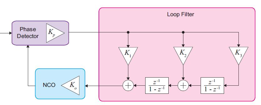
8 PHASE LOCK LOOP, REVIEW The is the fundamental component on every coherent receiver. : SYNC 8 Phase Detector: the output is proportional to the phase difference between received signal and locally generated. Controlled Oscillator: it is a VCO for analog receiver and NCO for digital receiver. Loop filter: Filter acts upon the output of the Phase Detector to remove unwanted high frequency terms, and produce the signal that drives the VCO or NCO.

9 PHASE DETECTOR The phase error is proportional to the phase difference: Implemented as a multiplier. If the difference is small, the mixing approach to the difference. 9
10 LOOP FILTER 10 The design of the loop filter is vital in defining the overall characteristics and behavior of the. The type corresponds to the number of integrators in the loop, including the one that add the VCO/NCO.
 The estimated phase at instant t is : k0 is the sensibility")
11 CONTROLLED OSCILLATOR The VCO control signal is the filtered phase difference v(t) The estimated phase at instant t is : k0 is the sensibility of VCO 11

12 NCO: NUMERICALLY CONTROLLED OSCILLATORS The digital version of VCO. 12 Different frequencies are created from different step size.

13 NCO To follow a frequency change, an adjustment term is needed. 13

14 NCO: IMPLEMENTATION ON FPGA The simplest operation inside FPGA could be up/down conversion to intermediate frequency. NCO are usually implemented on LUTs. Also called Digital Direct Synthesizer (DDS). 14 The LUT has N=2 n size, where n is the numbers of bits that accumulator generate. The amplitude resolution of the signal depends on the number of outputs bits L, and the frequency resolution depends on LUT size, n.
15 NCO ON FPGA Frequency and amplitude resolution 15
16 NCO ON FPGA Quantization effect, L 16

17 NCO ON FPGA Frequency control is done by the step of Accumulator 17

18 NCO ON FPGA The Accumulator step is determined by: N: number s entries on the LUT. Fs: sampling frequency Fd: desired frequency Example 8 bits, N=256, fs=10mhz, fd=2.5mhz If we need 2.4Mhz?? We need to add a fractional part to the ACC. The step will have an integer and a fractional part [n:b] μ= [8:4] 18

19 NCO ON FPGA Frequency resolution: depends on steps differences. The fractional bits should be selected following the desired frequency resolution. 19 Frequency resolution Δfa:
20 NCO ON FPGA Truncated error: if the step is μ=1.7, then spurious appear doe to truncate. 20
21 NCO ON FPGA TRUNCATED ERROR due to small N. Fs: 100kHz, fd: 24.3kHz, N:6, [n:b]=[6:16], L=32 21

22 NCO ON FPGA QAUNTIZATION ERROR, small L fs: 100kHz, fd: 24.3kHz, L:8, [n:b]=[12:16] 22

23 NCO ON FPGA SFDR: Range free of spurious frequencies GSM requires 110Db of SFDR 23


24 NCO ON FPGA Increase LUT size N help, but cost a lot. Better solution: add a dither signal to break the quantization error. Usually the number of dither bits is equal to fractional bits, b=d 24

25 NCO ON FPGA DIRECT DIGITAL SYNTHESIZER 25

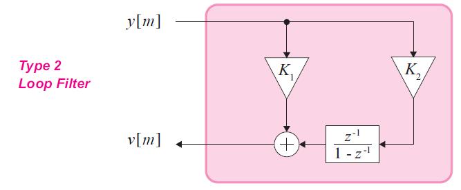
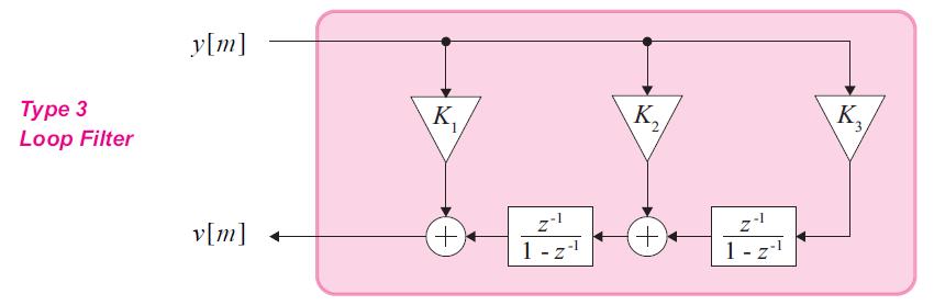
26 LOOP FILTERS TYPES 26
27 DESIGN PARAMETERS Time to achieve lock, depends on the step size. Steady state error, depends on the number of integrators and how the input signal change. Tracking capabilities, deepens on the type. 27
28 DAMPING RATIO under-damped over damped critically damped 28 The damping factor, or damping ratio, relates to the transient behavior of the as it achieves phase lock. Typical value is 0,707

29 BANDWIDTH The bandwidth refers to the range of frequencies over which the operates 29 At lower BW, bigger transient time at bigger BW lower transient. Cons: more noise into the.

30 COSTAS LOOP It is a type of used on AM-DSB-SC demodulation. Also used on M-PSK demodulations. It is based on the sin vs cos orthogonality. Principal advantage is its double sensibility. sen(2(θi θf)) Especially useful for Doppler effect correction. 30
31 COSTAS LOOP FPGA IMPLEMENTATION Decision Direct 31

32 COSTAS LOOP EXAMPLE 4QAM RX/TX 32
Lecture 11. Phase Locked Loop (PLL): Appendix C. EE4900/EE6720 Digital Communications
: Appendix C. EE4900/EE6720 Digital Communications") EE4900/EE6720: Digital Communications 1 Lecture 11 Phase Locked Loop (PLL): Appendix C Block Diagrams of Communication System Digital Communication System 2 Informatio n (sound, video, text, data, ) Transducer
EE4900/EE6720: Digital Communications 1 Lecture 11 Phase Locked Loop (PLL): Appendix C Block Diagrams of Communication System Digital Communication System 2 Informatio n (sound, video, text, data, ) Transducer
Synchronization. EE442 Lecture 17. All digital receivers must be synchronized to the incoming signal s(t).
.") Synchronization EE442 Lecture 17 All digital receivers must be synchronized to the incoming signal s(t). This means we must have a way to perform (1) Bit or symbol synchronization (2) Frame synchronization
Synchronization EE442 Lecture 17 All digital receivers must be synchronized to the incoming signal s(t). This means we must have a way to perform (1) Bit or symbol synchronization (2) Frame synchronization
Analog and Telecommunication Electronics
 Politecnico di Torino - ICT School Analog and Telecommunication Electronics C1 - PLL linear analysis» PLL basics» Application examples» Linear analysis» Phase error 08/04/2011-1 ATLCE - C1-2010 DDC Lesson
Modulation is the process of impressing a low-frequency information signal (baseband signal) onto a higher frequency carrier signal
 onto a higher frequency carrier signal") Modulation is the process of impressing a low-frequency information signal (baseband signal) onto a higher frequency carrier signal Modulation is a process of mixing a signal with a sinusoid to produce
Modulation is the process of impressing a low-frequency information signal (baseband signal) onto a higher frequency carrier signal Modulation is a process of mixing a signal with a sinusoid to produce
Digital Communication
 Digital Communication Laboratories bako@ieee.org DigiCom Labs There are 5 labs related to the digital communication. Study of the parameters of metal cables including: characteristic impendance, attenuation
THE UNIVERSITY OF NAIROBI
 THE UNIVERSITY OF NAIROBI ELECTRICAL AND INFORMATION ENGINEERING DEPARTMENT FINAL YEAR PROJECT. PROJECT NO. 085. TITLE: A PHASE-LOCKED LOOP FREQUENCY SYNTHESIZER BY: TUNDULI W. MICHAEL F17/2143/2004. SUPERVISOR:
TESTING METHODS AND ERROR BUDGET ANALYSIS OF A SOFTWARE DEFINED RADIO By Richard Overdorf
 TESTING METHODS AND ERROR BUDGET ANALYSIS OF A SOFTWARE DEFINED RADIO By Richard Overdorf SDR Considerations Data rates Voice Image Data Streaming Video Environment Distance Terrain High traffic/low traffic
Twelve voice signals, each band-limited to 3 khz, are frequency -multiplexed using 1 khz guard bands between channels and between the main carrier
 Twelve voice signals, each band-limited to 3 khz, are frequency -multiplexed using 1 khz guard bands between channels and between the main carrier and the first channel. The modulation of the main carrier
During most of the race, each car is on its own and free to pass the other and lap the other. This is analogous to the PLL in an unlocked state.
 PHASE-LOCKED LOOP A phase-locked loop or phase lock loop abbreviated as PLL is a control system that generates an output signal whose phase is related to the phase of an input signal. There are several
Problems from the 3 rd edition
 (2.1-1) Find the energies of the signals: a) sin t, 0 t π b) sin t, 0 t π c) 2 sin t, 0 t π d) sin (t-2π), 2π t 4π Problems from the 3 rd edition Comment on the effect on energy of sign change, time shifting
PHASELOCK TECHNIQUES INTERSCIENCE. Third Edition. FLOYD M. GARDNER Consulting Engineer Palo Alto, California A JOHN WILEY & SONS, INC.
 PHASELOCK TECHNIQUES Third Edition FLOYD M. GARDNER Consulting Engineer Palo Alto, California INTERSCIENCE A JOHN WILEY & SONS, INC., PUBLICATION CONTENTS PREFACE NOTATION xvii xix 1 INTRODUCTION 1 1.1
Software-Defined Radio using Xilinx (SoRaX)
") SoRaX-Page 1 Software-Defined Radio using Xilinx (SoRaX) Functional Requirements List and Performance Specifications By: Anton Rodriguez & Mike Mensinger Project Advisors: Dr. In Soo Ahn & Dr. Yufeng Lu
SoRaX-Page 1 Software-Defined Radio using Xilinx (SoRaX) Functional Requirements List and Performance Specifications By: Anton Rodriguez & Mike Mensinger Project Advisors: Dr. In Soo Ahn & Dr. Yufeng Lu
Channelization and Frequency Tuning using FPGA for UMTS Baseband Application
 Channelization and Frequency Tuning using FPGA for UMTS Baseband Application Prof. Mahesh M.Gadag Communication Engineering, S. D. M. College of Engineering & Technology, Dharwad, Karnataka, India Mr.
PCM BIT SYNCHRONIZATION TO AN Eb/No THRESHOLD OF -20 db
 PCM BIT SYNCHRONIZATION TO AN Eb/No THRESHOLD OF -20 db Item Type text; Proceedings Authors Schroeder, Gene F. Publisher International Foundation for Telemetering Journal International Telemetering Conference
Multiple Reference Clock Generator
 A White Paper Presented by IPextreme Multiple Reference Clock Generator Digitial IP for Clock Synthesis August 2007 IPextreme, Inc. This paper explains the concept behind the Multiple Reference Clock Generator
Carrier Phase Recovery. EE3723 : Digital Communications. Synchronization. Carrier Phase Recovery. Carrier Phase Synchronization Techniques.
 EE3723 : Digital Communications Carrier Phase Recovery Week 10: Synchronization (Frequency, Phase, Symbol and Frame Synchronization) Carrier and Phase Recovery Phase-Locked Loop 20-May-15 Muhammad Ali
 Modulations Analog Modulations Amplitude modulation (AM) Linear modulation Frequency modulation (FM) Phase modulation (PM) cos Angle modulation FM PM Digital Modulations ASK FSK PSK MSK MFSK QAM PAM Etc.
Glossary of VCO terms
 Glossary of VCO terms VOLTAGE CONTROLLED OSCILLATOR (VCO): This is an oscillator designed so the output frequency can be changed by applying a voltage to its control port or tuning port. FREQUENCY TUNING
AC LAB ECE-D ecestudy.wordpress.com
 PART B EXPERIMENT NO: 1 AIM: PULSE AMPLITUDE MODULATION (PAM) & DEMODULATION DATE: To study Pulse Amplitude modulation and demodulation process with relevant waveforms. APPARATUS: 1. Pulse amplitude modulation
Analog and Telecommunication Electronics
 Politecnico di Torino Electronic Eng. Master Degree Analog and Telecommunication Electronics C5 - Synchronous demodulation» AM and FM demodulation» Coherent demodulation» Tone decoders AY 2015-16 19/03/2016-1
A Low Area, Switched-Resistor Loop Filter Technique for Fractional-N Synthesizers Applied to a MEMS-based Programmable Oscillator
 A Low Area, Switched-Resistor Loop Filter Technique for Fractional-N Synthesizers Applied to a MEMS-based Programmable Oscillator ISSCC 00, Session 3. M.H. Perrott, S. Pamarti, E. Hoffman, F.S. Lee, S.
Local Oscillator Phase Noise and its effect on Receiver Performance C. John Grebenkemper
 Watkins-Johnson Company Tech-notes Copyright 1981 Watkins-Johnson Company Vol. 8 No. 6 November/December 1981 Local Oscillator Phase Noise and its effect on Receiver Performance C. John Grebenkemper All
9 Best Practices for Optimizing Your Signal Generator Part 2 Making Better Measurements
 9 Best Practices for Optimizing Your Signal Generator Part 2 Making Better Measurements In consumer wireless, military communications, or radar, you face an ongoing bandwidth crunch in a spectrum that
FFT Based Carrier Recovery with Lower Processing Speed Using DSP Techniques
 FFT Based Carrier Recovery with Lower Processing Speed Using DSP Techniques Vikas Kumar 1, Divya K. N 2 1,2 RFC-BEL Bangalore, MIT Manipal ABSTRACT Carrier recovery is one of most important block during
DATASHEET HSP Features. Description. Applications. Ordering Information. Block Diagram. Digital QPSK Demodulator. FN4162 Rev 3.
 DATASHEET HSP50306 Digital QPSK Demodulator Features 25.6MHz or 26.97MHz Clock Rates Single Chip QPSK Demodulator with 10kHz Tracking Loop Square Root of Raised Cosine ( = 0.4) Matched Filtering 2.048
Analysis of Phase Noise Profile of a 1.1 GHz Phase-locked Loop
 Analysis of Phase Noise Profile of a 1.1 GHz Phase-locked Loop J. Handique, Member, IAENG and T. Bezboruah, Member, IAENG 1 Abstract We analyzed the phase noise of a 1.1 GHz phaselocked loop system for
Code No: R Set No. 1
 Code No: R05220405 Set No. 1 II B.Tech II Semester Regular Examinations, Apr/May 2007 ANALOG COMMUNICATIONS ( Common to Electronics & Communication Engineering and Electronics & Telematics) Time: 3 hours
Integrated Circuit Design for High-Speed Frequency Synthesis
 Integrated Circuit Design for High-Speed Frequency Synthesis John Rogers Calvin Plett Foster Dai ARTECH H O US E BOSTON LONDON artechhouse.com Preface XI CHAPTER 1 Introduction 1 1.1 Introduction to Frequency
Exercise 2: FM Detection With a PLL
 Phase-Locked Loop Analog Communications Exercise 2: FM Detection With a PLL EXERCISE OBJECTIVE When you have completed this exercise, you will be able to explain how the phase detector s input frequencies
EE 460L University of Nevada, Las Vegas ECE Department
 EE 460L PREPARATION 1- ASK Amplitude shift keying - ASK - in the context of digital communications is a modulation process which imparts to a sinusoid two or more discrete amplitude levels. These are related
Realization of Programmable BPSK Demodulator-Bit Synchronizer using Multirate Processing
 International Journal of Electrical and Computer Engineering (IJECE) Vol. 4, No. 3, June 2014, pp. 433~440 ISSN: 2088-8708 433 Realization of Programmable BPSK Demodulator-Bit Synchronizer using Multirate
Hardware/Software Co-Simulation of BPSK Modulator and Demodulator using Xilinx System Generator
 www.semargroups.org, www.ijsetr.com ISSN 2319-8885 Vol.02,Issue.10, September-2013, Pages:984-988 Hardware/Software Co-Simulation of BPSK Modulator and Demodulator using Xilinx System Generator MISS ANGEL
Enhancing FPGA-based Systems with Programmable Oscillators
 Enhancing FPGA-based Systems with Programmable Oscillators Jehangir Parvereshi, jparvereshi@sitime.com Sassan Tabatabaei, stabatabaei@sitime.com SiTime Corporation www.sitime.com 990 Almanor Ave., Sunnyvale,
Fundamentals of Arbitrary. Waveform Generation
 Fundamentals of Arbitrary Waveform Generation History Applications Key Specifications Optimization Signal fidelity and dynamic range Embedding and de-embedding Waveform generation and automation software
Section 1. Fundamentals of DDS Technology
 Section 1. Fundamentals of DDS Technology Overview Direct digital synthesis (DDS) is a technique for using digital data processing blocks as a means to generate a frequency- and phase-tunable output signal
EE470 Electronic Communication Theory Exam II
 EE470 Electronic Communication Theory Exam II Open text, closed notes. For partial credit, you must show all formulas in symbolic form and you must work neatly!!! Date: November 6, 2013 Name: 1. [16%]
Lecture 6. Angle Modulation and Demodulation
 Lecture 6 and Demodulation Agenda Introduction to and Demodulation Frequency and Phase Modulation Angle Demodulation FM Applications Introduction The other two parameters (frequency and phase) of the carrier
LOW DATA RATE BPSK DEMODULATION IN PRESENCE OF DOPPLER
 LOW DATA RATE BPSK DEMODULATION IN PRESENCE OF DOPPLER Aghanash Karthik 1 Ashwin.R 2, Dr.Sambasiva Rao.V 3, Prof. V. Mahadevan 4 1,2,3 Dept. of ECE, PESIT, Bangalore, 4 Dept. of TCE, PESIT, Bangalore Abstract
Accurate Phase Noise Measurements Made Cost Effective
 MTTS 2008 MicroApps Accurate Phase Noise Measurements Made Cost Effective author : Jason Breitbarth, PhD. Boulder, Colorado, USA Presentation Outline Phase Noise Intro Additive and Absolute Oscillator
Solution of ECE 342 Test 3 S12
 Solution of ECE 34 Test 3 S1 1 A random power signal has a mean of three and a standard deviation of five Find its numerical total average signal power Signal Power P = 3 + 5 = 34 A random energy signal
Development of Signal Analyzer MS2840A with Built-in Low Phase-Noise Synthesizer
 Development of Signal Analyzer MS2840A with Built-in Low Phase-Noise Synthesizer Toru Otani, Koichiro Tomisaki, Naoto Miyauchi, Kota Kuramitsu, Yuki Kondo, Junichi Kimura, Hitoshi Oyama [Summary] Evaluation
Session 3. CMOS RF IC Design Principles
 Session 3 CMOS RF IC Design Principles Session Delivered by: D. Varun 1 Session Topics Standards RF wireless communications Multi standard RF transceivers RF front end architectures Frequency down conversion
Lecture 12. Carrier Phase Synchronization. EE4900/EE6720 Digital Communications
 EE49/EE6720: Digital Communications 1 Lecture 12 Carrier Phase Synchronization Block Diagrams of Communication System Digital Communication System 2 Informatio n (sound, video, text, data, ) Transducer
Universitas Sumatera Utara
 Amplitude Shift Keying & Frequency Shift Keying Aim: To generate and demodulate an amplitude shift keyed (ASK) signal and a binary FSK signal. Intro to Generation of ASK Amplitude shift keying - ASK -
DS H01 DIGITAL SYNTHESIZER MODULE SYSTEM SOLUTIONS. Features Applications 174 x 131 x 54 mm. Technical Description
 DS H01 The DS H01 is a high performance dual digital synthesizer with wide output bandwidth specially designed for Defense applications where generation of wideband ultra-low noise signals along with very
CARRIER RECOVERY BY RE-MODULATION IN QPSK
 CARRIER RECOVERY BY RE-MODULATION IN QPSK PROJECT INDEX : 093 BY: YEGO KIPLETING KENNETH REG. NO. F17/1783/2006 SUPERVISOR: DR. V.K. ODUOL EXAMINER: PROF. ELIJAH MWANGI 24 TH MAY 2011 OBJECTIVES Study
CME312- LAB Manual DSB-SC Modulation and Demodulation Experiment 6. Experiment 6. Experiment. DSB-SC Modulation and Demodulation
 Experiment 6 Experiment DSB-SC Modulation and Demodulation Objectives : By the end of this experiment, the student should be able to: 1. Demonstrate the modulation and demodulation process of DSB-SC. 2.
Keywords: FPGA, Software Define Radio, QAM, Synchronization, Wireless Communication, Carrier Recovery, System Generator, BPSK.
 ISSN 2322-0929 Vol.02,Issue.01, January-2014, Pages:0080-0087 ww.semargroup.org www.ijvdcs.org Design and FPGA Implementation of a BPSK Modem on Modern DSP Technology for Wireless Communication B. RAJASEKHARA
OBJECTIVES EQUIPMENT LIST
 1 Reception of Amplitude Modulated Signals AM Demodulation OBJECTIVES The purpose of this experiment is to show how the amplitude-modulated signals are demodulated to obtain the original signal. Also,
Design and Implementation of PLL for Frequency Demodulation
 Design and Implementation of PLL for Frequency Demodulation MA. Jihan S. Abdaljabar, HaithamK.Ali Abstract: Frequency modulation is widely used in radio transmissions, especially, in the broadcasting of
Phase-Locked Loops. Roland E. Best. Me Graw Hill. Sixth Edition. Design, Simulation, and Applications
 Phase-Locked Loops Design, Simulation, and Applications Roland E. Best Sixth Edition Me Graw Hill New York Chicago San Francisco Lisbon London Madrid Mexico City Milan New Delhi San Juan Seoul Singapore
HF Receivers, Part 3
 HF Receivers, Part 3 Introduction to frequency synthesis; ancillary receiver functions Adam Farson VA7OJ View an excellent tutorial on receivers Another link to receiver principles NSARC HF Operators HF
Preliminary features of the SDR-X receiver SDR-X , PowerSDR Winrad Winrad DDS SFDR SFDR AD995 AD99 1
 Preliminary features of the SDR-X receiver The SDR-X receiver, in its full version is capable of continuously tuning the entire HF spectrum, 6m ( 50-52 MHz) band included. SSB, AM etc. demodulation, bandpass
Outline. Communications Engineering 1
 Outline Introduction Signal, random variable, random process and spectra Analog modulation Analog to digital conversion Digital transmission through baseband channels Signal space representation Optimal
PTX-0350 RF UPCONVERTER, MHz
 PTX-0350 RF UPCONVERTER, 300 5000 MHz OPERATING MODES I/Q upconverter RF = LO + IF upconverter RF = LO - IF upconverter Synthesizer 10 MHz REFERENCE INPUT/OUTPUT EXTERNAL LOCAL OSCILLATOR INPUT I/Q BASEBAND
TSEK02: Radio Electronics Lecture 8: RX Nonlinearity Issues, Demodulation. Ted Johansson, EKS, ISY
 TSEK02: Radio Electronics Lecture 8: RX Nonlinearity Issues, Demodulation Ted Johansson, EKS, ISY RX Nonlinearity Issues: 2.2, 2.4 Demodulation: not in the book 2 RX nonlinearities System Nonlinearity
THIS work focus on a sector of the hardware to be used
 DISSERTATION ON ELECTRICAL AND COMPUTER ENGINEERING 1 Development of a Transponder for the ISTNanoSAT (November 2015) Luís Oliveira luisdeoliveira@tecnico.ulisboa.pt Instituto Superior Técnico Abstract
Choosing Loop Bandwidth for PLLs
 Choosing Loop Bandwidth for PLLs Timothy Toroni SVA Signal Path Solutions April 2012 1 Phase Noise (dbc/hz) Choosing a PLL/VCO Optimized Loop Bandwidth Starting point for setting the loop bandwidth is
Testing Upstream and Downstream DOCSIS 3.1 Devices
 Testing Upstream and Downstream DOCSIS 3.1 Devices April 2015 Steve Hall DOCSIS 3.1 Business Development Manager Agenda 1. Decoding and demodulating a real downstream DOCSIS 3.1 signal and reporting key
DDC_DEC. Digital Down Converter with configurable Decimation Filter Rev Block Diagram. Key Design Features. Applications. Generic Parameters
 Key Design Features Block Diagram Synthesizable, technology independent VHDL Core 16-bit signed input/output samples 1 Digital oscillator with > 100 db SFDR Digital oscillator phase resolution of 2π/2
Revision of Lecture 2
 Revision of Lecture 2 Pulse shaping Tx/Rx filter pair Design of Tx/Rx filters (pulse shaping): to achieve zero ISI and to maximise received signal to noise ratio Combined Tx/Rx filters: Nyquist system
RFID Systems: Radio Architecture
 RFID Systems: Radio Architecture 1 A discussion of radio architecture and RFID. What are the critical pieces? Familiarity with how radio and especially RFID radios are designed will allow you to make correct
SiNANO-NEREID Workshop:
 SiNANO-NEREID Workshop: Towards a new NanoElectronics Roadmap for Europe Leuven, September 11 th, 2017 WP3/Task 3.2 Connectivity RF and mmw Design Outline Connectivity, what connectivity? High data rates
Section 8. Replacing or Integrating PLL s with DDS solutions
 Section 8. Replacing or Integrating PLL s with DDS solutions By Rick Cushing, Applications Engineer, Analog Devices, Inc. DDS vs Standard PLL PLL (phase-locked loop) frequency synthesizers are long-time
DESIGN OF HIGH FREQUENCY CMOS FRACTIONAL-N FREQUENCY DIVIDER
 12 JAVA Journal of Electrical and Electronics Engineering, Vol. 1, No. 1, April 2003 DESIGN OF HIGH FREQUENCY CMOS FRACTIONAL-N FREQUENCY DIVIDER Totok Mujiono Dept. of Electrical Engineering, FTI ITS
BPSK Modulator and Demodulator
 RadFXSat- (Fox-1E) BPSK Modulator and Demodulator Chris Thompson, G0KLA / ACCZ November 018 1 Requirements Fox-1E RF Design required a 45MHz carrier with PSK modulation, to mix with TX signal Had to work
TRANSMISSION OF RADIOMETER DATA FROM THE SYNCHRONOUS METEOROLOGICAL SATELLITE
 TRANSMISSION OF RADIOMETER DATA FROM THE SYNCHRONOUS METEOROLOGICAL SATELLITE Item Type text; Proceedings Authors Davies, Richard S. Publisher International Foundation for Telemetering Journal International
High-speed Serial Interface
 High-speed Serial Interface Lect. 9 PLL (Introduction) 1 Block diagram Where are we today? Serializer Tx Driver Channel Rx Equalizer Sampler Deserializer PLL Clock Recovery Tx Rx 2 Clock Clock: Timing
The DR-2000 is a high-performance receiver designed to enable highly sophisticated data and signal processing over a wide frequency spectrum.
 The DR-2000 is a high-performance receiver designed to enable highly sophisticated data and signal processing over a wide frequency spectrum. L3 (L3 T&RF) DR-2000 receiving unit incorporates a high-performance
VHDL Implementation of High Performance Digital Up Converter Using Multi-DDS Technology For Radar Transmitters
 VHDL Implementation of High Performance Digital Up Converter Using Multi-DDS Technology For Radar Transmitters Ganji Ramu M. Tech Student, Department of Electronics and Communication Engineering, SLC s
Amplitude Modulated Systems
 Amplitude Modulated Systems Communication is process of establishing connection between two points for information exchange. Channel refers to medium through which message travels e.g. wires, links, or
Direct Digital Synthesis Primer
 Direct Digital Synthesis Primer Ken Gentile, Systems Engineer ken.gentile@analog.com David Brandon, Applications Engineer David.Brandon@analog.com Ted Harris, Applications Engineer Ted.Harris@analog.com
Phase-Locked Loop Engineering Handbook for Integrated Circuits
 Phase-Locked Loop Engineering Handbook for Integrated Circuits Stanley Goldman ARTECH H O U S E BOSTON LONDON artechhouse.com Preface Acknowledgments xiii xxi CHAPTER 1 Cetting Started with PLLs 1 1.1
Antenna Measurements using Modulated Signals
 Antenna Measurements using Modulated Signals Roger Dygert MI Technologies, 1125 Satellite Boulevard, Suite 100 Suwanee, GA 30024-4629 Abstract Antenna test engineers are faced with testing increasingly
Understanding Low Phase Noise Signals. Presented by: Riadh Said Agilent Technologies, Inc.
 Understanding Low Phase Noise Signals Presented by: Riadh Said Agilent Technologies, Inc. Introduction Instabilities in the frequency or phase of a signal are caused by a number of different effects. Each
The best radio for worst events. Over HF links. Hana Rafi - CEO Eder Yehuda - VP R&D
 MOBAT MICOM The best radio for worst events Increasing Data Throughput Over HF links Hana Rafi - CEO Eder Yehuda - VP R&D 1 Traditional HF Radio -Analog voice & 50,75 bps New Trends on HF - Digital voice,
DEVELOPMENT OF SOFTWARE RADIO PROTOTYPE
 DEVELOPMENT OF SOFTWARE RADIO PROTOTYPE Isao TESHIMA; Kenji TAKAHASHI; Yasutaka KIKUCHI; Satoru NAKAMURA; Mitsuyuki GOAMI; Communication Systems Development Group, Hitachi Kokusai Electric Inc., Tokyo,
Lecture 7: Components of Phase Locked Loop (PLL)
") Lecture 7: Components of Phase Locked Loop (PLL) CSCE 6933/5933 Instructor: Saraju P. Mohanty, Ph. D. NOTE: The figures, text etc included in slides are borrowed from various books, websites, authors pages,
Lecture 7: Components of Phase Locked Loop (PLL) CSCE 6933/5933 Instructor: Saraju P. Mohanty, Ph. D. NOTE: The figures, text etc included in slides are borrowed from various books, websites, authors pages,
Chapter 2 Analysis of Quantization Noise Reduction Techniques for Fractional-N PLL
 Chapter 2 Analysis of Quantization Noise Reduction Techniques for Fractional-N PLL 2.1 Background High performance phase locked-loops (PLL) are widely used in wireless communication systems to provide
TSEK02: Radio Electronics Lecture 8: RX Nonlinearity Issues, Demodulation. Ted Johansson, EKS, ISY
 TSEK02: Radio Electronics Lecture 8: RX Nonlinearity Issues, Demodulation Ted Johansson, EKS, ISY 2 RX Nonlinearity Issues, Demodulation RX nonlinearities (parts of 2.2) System Nonlinearity Sensitivity
Research on DQPSK Carrier Synchronization based on FPGA
 Journal of Information Hiding and Multimedia Signal Processing c 27 ISSN 273-422 Ubiquitous International Volume 8, Number, January 27 Research on DQPSK Carrier Synchronization based on FPGA Shi-Jun Kang,
23cm PSK packet-radio RTX for 1.2Mbit/s user access Matjaz Vidmar, S53MV
 23cm PSK packet-radio RTX for 1.2Mbit/s user access --------------------------------------------------Matjaz Vidmar, S53MV 1. Why biphase PSK modulation? -----------------------------Upgrading the packet-radio
The RCB-2000 is a compact receiving system that combines two high-performance telemetry RF sections.
 The RCB-2000 is a compact receiving system that combines two high-performance telemetry RF sections. L3 Telemetry& RF products (L3 T&RF) RCB-2000 is a compact, receiving system that combines two high-performance
Periodic Wave Generation for Direct Digital Synthesization
 International Journal on Intelligent Electronics Systems, Vol. 10 No.1 January 2016 22 Periodic Wave Generation for Direct Digital Synthesization Abstract Govindaswamy Indhumathi 1 Dr.R. Seshasayanan 2
Modeling Communication Systems Using Simulink
 Modeling Communication Systems Using Simulink DSB-SC Modulation System Model Eng. Anas Alashqar Modeling Communication Systems Using Simulink: DSB-SC Modulation System Model Eng. Anas Alashqar Publication
Fabricate a 2.4-GHz fractional-n synthesizer
 University of Malaya From the SelectedWorks of Professor Mahmoud Moghavvemi Summer June, 2013 Fabricate a 2.4-GHz fractional-n synthesizer H Ameri Mahmoud Moghavvemi, University of Malaya a Attaran Available
Chapter-15. Communication systems -1 mark Questions
 Chapter-15 Communication systems -1 mark Questions 1) What are the three main units of a Communication System? 2) What is meant by Bandwidth of transmission? 3) What is a transducer? Give an example. 4)
EE 400L Communications. Laboratory Exercise #7 Digital Modulation
 EE 400L Communications Laboratory Exercise #7 Digital Modulation Department of Electrical and Computer Engineering University of Nevada, at Las Vegas PREPARATION 1- ASK Amplitude shift keying - ASK - in
LNS ultra low phase noise Synthesizer 8 MHz to 18 GHz
 LNS ultra low phase noise Synthesizer 8 MHz to 18 GHz Datasheet The LNS is an easy to use 18 GHz synthesizer that exhibits outstanding phase noise and jitter performance in a 3U rack mountable chassis.
Experiment 7: Frequency Modulation and Phase Locked Loops
 Experiment 7: Frequency Modulation and Phase Locked Loops Frequency Modulation Background Normally, we consider a voltage wave form with a fixed frequency of the form v(t) = V sin( ct + ), (1) where c
DIRECT UP-CONVERSION USING AN FPGA-BASED POLYPHASE MODEM
 DIRECT UP-CONVERSION USING AN FPGA-BASED POLYPHASE MODEM Rob Pelt Altera Corporation 101 Innovation Drive San Jose, California, USA 95134 rpelt@altera.com 1. ABSTRACT Performance requirements for broadband
Costas Loop. Modules: Sequence Generator, Digital Utilities, VCO, Quadrature Utilities (2), Phase Shifter, Tuneable LPF (2), Multiplier
, Phase Shifter, Tuneable LPF (2), Multiplier") Costas Loop Modules: Sequence Generator, Digital Utilities, VCO, Quadrature Utilities (2), Phase Shifter, Tuneable LPF (2), Multiplier 0 Pre-Laboratory Reading Phase-shift keying that employs two discrete
Costas Loop Modules: Sequence Generator, Digital Utilities, VCO, Quadrature Utilities (2), Phase Shifter, Tuneable LPF (2), Multiplier 0 Pre-Laboratory Reading Phase-shift keying that employs two discrete
PROPAGATION CHANNEL EMULATOR : ECP
 PROPAGATION CHANNEL EMULATOR : ECP The ECP (Propagation Channel Emulator) synthesizes the principal phenomena of propagation occurring on RF signal links between earth and space. Developed by the R&D laboratory,
Agile Low-Noise Frequency Synthesizer A. Ridenour R. Aurand Spectrum Microwave
 Agile Low-Noise Frequency Synthesizer A. Ridenour R. Aurand Spectrum Microwave Abstract Simultaneously achieving low phase noise, fast switching speed and acceptable levels of spurious outputs in microwave
ADI 2006 RF Seminar. Chapter II RF/IF Components and Specifications for Receivers
 ADI 2006 RF Seminar Chapter II RF/IF Components and Specifications for Receivers 1 RF/IF Components and Specifications for Receivers Fixed Gain and Variable Gain Amplifiers IQ Demodulators Analog-to-Digital
Modulation (7): Constellation Diagrams
: Constellation Diagrams") Modulation (7): Constellation Diagrams Luiz DaSilva Professor of Telecommunications dasilval@tcd.ie +353-1-8963660 Adapted from material by Dr Nicola Marchetti Geometric representation of modulation signal
Modulation (7): Constellation Diagrams Luiz DaSilva Professor of Telecommunications dasilval@tcd.ie +353-1-8963660 Adapted from material by Dr Nicola Marchetti Geometric representation of modulation signal
Signals and Systems Lecture 9 Communication Systems Frequency-Division Multiplexing and Frequency Modulation (FM)
") Signals and Systems Lecture 9 Communication Systems Frequency-Division Multiplexing and Frequency Modulation (FM) April 11, 2008 Today s Topics 1. Frequency-division multiplexing 2. Frequency modulation
Signals and Systems Lecture 9 Communication Systems Frequency-Division Multiplexing and Frequency Modulation (FM) April 11, 2008 Today s Topics 1. Frequency-division multiplexing 2. Frequency modulation
Communication Channels
 Communication Channels wires (PCB trace or conductor on IC) optical fiber (attenuation 4dB/km) broadcast TV (50 kw transmit) voice telephone line (under -9 dbm or 110 µw) walkie-talkie: 500 mw, 467 MHz
PRODUCT DEMODULATION - SYNCHRONOUS & ASYNCHRONOUS
 PRODUCT DEMODULATION - SYNCHRONOUS & ASYNCHRONOUS INTRODUCTION...98 frequency translation...98 the process...98 interpretation...99 the demodulator...100 synchronous operation: ω 0 = ω 1...100 carrier
Now cover 1296 MHz. TransFox Highlights
 Now cover 1296 MHz TransFox Highlights General coverage 1-1450 MHz Outstanding LO resolution (1Hz), phase noise & lock times thanks to SynFox technology Brings unique VHF, UHF and SHF coverage to SDR SDR