The best radio for worst events. Over HF links. Hana Rafi - CEO Eder Yehuda - VP R&D
|
|
|
- Gwenda Goodwin
- 6 years ago
- Views:
Transcription
1 MOBAT MICOM The best radio for worst events Increasing Data Throughput Over HF links Hana Rafi - CEO Eder Yehuda - VP R&D 1
2 Traditional HF Radio -Analog voice & 50,75 bps New Trends on HF - Digital voice, Noise reduction - High Data Rate bps QAM High linearity, SNR,Efficiency 2
3 Requirements from the New HF Radio For HDR performance -Linearity - ISI -High dyn. range -Low ACI & IBN -High Power TX. -High efficiency -Small size. -High MTBF. -feasible. 3
4 HPA and High Data Rate (HDR) Traditional TX Inter-Mod HDR RX SNR Requirements : 31dB : >33 db PSD 31dB SNR ~30dB Frequency 4
5 micom Radio &HPA Solution Linearized Power Amplifier : New MICOM C Spec. Current Spec. Achivments TX PWR 125/175W 125W Availability Inter-Mod >42 db 30-32dB Data Rate Efficiency i >45% 30% Energy PWR con. 280 /390W 416W Size 5
6 Efficiency V.S. PAR (Peak to Average Ratio) Power density probability npsk efficiency CPFSK nqam -5dbm 0dbm Power level 6
7 New HF Generation & micom HDR Road-Map n*isb Radio, 125/175W and HPA HDR Modems 9600, K bps Enhanced STD gateway (IP) Enhanced digital voice 7
8 Technical session on Linearized techniques & Achievements on micom radio Mr. Yehuda Eder Thank you, have a productive day 8
9 Problem description Pout Linear Non Linearity caused by: PSD ACI BBN Pin PA/transmitter linearization RGC Receiver Gain Control TGC/ALC Transmitter Gain Control D/A-A/D Resolutions Local Oscillators phase noise Receiver/Transmitter BW Group Delay Variation ISI IBN Freq. 9
10 Available Solutions Linear Power Transceiver : Linear Power Amplifier, Class-A or A/B with large backoff : Low efficiency, high cost AGC, TGC,ALC : HELD (Input regulation based on average signal level should be held) HF channel receive signal variations may cause problems to the receiver performance and the linearity. Linearized Power Amplifier High Efficiency and IMD 10
11 RGC Receiver Gain Control TGC/ALC Transmitter Transmitter Gain Control Special techniques for attack-release of GAIN CONTROL must be used. T > delta between 2 peaks Data AGC GAIN Typical AGC TIME 11
12 A/D D/A Quantizing Noise Distortion & Noise in CODECs Integral non-linearity Differential non-linearity. Total Harmonic Distortion (THD). Total Harmonic Distortion Plus Noise (THD+N) Signal to Noise and Distortion Ratio (SINAD, or S/N+D). Effective Number Of Bits (ENOB). Signal to Noise Ratio (SNR). Analog Bandwidth (Full Power, Small Signal) Spurious Free Dynamic Range (SFDR). Two Tone Inter-modulation Distortion. Noise Power Ratio (NPR). 12
13 Local/Synthesizer Oscillators phase noise The synthesizer is the source of: IBN BBN High noise near the carrier = SNR degradation 13
14 Receiver/Transmitter BW In band ripple Group delay variances 14
15 PA characteristics - linear scale 15
16 Typical class AB PA characteristics (measurements) Power Gain Phase Transfer Function 16
17 PA linearity vs. SNR MIL-STD B Requirement: Intermodulation distortion (IMD). The IMD products of HF transmitters produced by any two equal-level signals within the 3 db bandwidth shall be at least 30 db below either tone for fixed station application, and 24 db below either tone for tactical application. The 24/30dB limits the SNR performance. Summary Performance tests results: IMD (below tone) SNR the IMD should be improved for better SNR 17
18 PA Linearization Techniques Power Amplifier Linearization Techniques: Feed Forward Pre-Distortion EER Envelope Elimination Restoration Cartesian Feedback Our approach: High Efficiency Class-AB amplifier with Cartesian Feedback & EER to achieve high linearity and high efficiency. 18
19 Linearization Techniques Feed-forward V i P. A. 2 G V o 1 G 2 2 Error Amplifier - High complexity -Wide BW - Low freq. Range 19
20 Linearization Techniques pre-distortion V o F(*) linear V i Predistorter V i V i V m P. A. V o V i F(V m ) - High complexity V i V m -Wide BW -Low freq. Range 20
21 Linearization Technique Digital adaptive pre-distortion L. O. I \ Q Mod. P. A. F(V m ) V o Adaptive Predistortion Predistorted Phi(kT s ) D / A D / A I(kT s ) Q(kT s ) Polar to C artesian Pre-distortion calculation Var. At tt. D a t a I/Q (kt s ) Cartesian to Polar Amp(kT s ) A d r e s s Look-up table (A i,phi i ) old (A i,phi i ) new A / D I \ Q Demod. D em odutated I/Q (kt s ) Adaptation algorithm Tables RF / analog elements Digital elements Down Converter 21

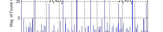
22 Linearization Technique Digital Pre-distortion - Preliminary Results 22
23 EER (Envelope Elimination and Restoration) Envelope modulator S t V ( ) 1 t V DD V i t V ( t) cos t ( t) c Signal separation t cos t ( ) S c 2 t P. A. V o -High Efficiency - limited performance 23
24 PA without AM- AM loopto PM I pol =[ ] ; Q pol =0 Gain PA Characteristics ti Two Tone Intermodulation. ti - AM loop 40 green - Source blue - PA red - PA with linearizer Vin [Volt] Amp [db] Phase [ o ] Vin [Volt] IM3 = 25 dbc AM loop improvement > 20 db
25 PA with AM-to-PM ( 0 25 ) AM loop I pol =[ ] ; Q pol =[ ] Gain PA Characteristics green - Source blue - PA red - PA with linearizer Two Tone Intermodulation. - AM loop Vin [Volt] 180 mp [db] A -20 Phase [ o ] Vin [Volt] IM3 = 25 dbc AM loop improvement = db For QAM modulation Cartesian loop is required
26 Analog Cartesian Loop -Block Diagram Closed loop, Narrowband (< 200 khz) S nom = 43 dbm S max = 50 dbm ; S min = 30 dbm N max = dbm / Hz RF Out S LO = 10 +/- 2 dbm L.O (Syn) AMP coup. (10dB) I/Q Modulator (17 dbm mixer) AMP digital atten. 15 db AMP digital atten. 15 db AMP P A - 2 db LPF Directional Coupler -20 db I_Tx Q_Tx loop filter -6 db splitter I_T s Q_T s f s FPGA 12 D / A LPF I REF loop filter err_i + err_q 12 Q D / A LPF REF + - RF components - Analog components Offset and I / Q balance compensation circuits Digital components I_dem Q_dem atten. 4 B AMP I/Q DeMod. (17 dbm mixer) digital atten. 15 db atten. 5 db atten. 10 db 26
27 Analog Cartesian Loop Performance 27
28 Micom Linearization solution EER & Cartesian loop 110 V AC (option) P IN =1 Watt Signal Processing Unit RF modulated-to-polar 28 / 48 V DC LPF Envelope DC P.S. LPF DC feedback Harmonic filter P TX =500 Watt Cartesian Linearization (complex closed loop) Phase modulated RF P A Att. 28
29 Micom Radio implementation DSP/ FPGA Digital BB Reconst. LPF IF 1 =1.05 MHz Digital IF D/A BPF IF 2 = 1.05 MHz BW= 12.1 KHz Envelope follower Bi-directional IF amp. BPF IF 2 = 45.1 MHz BW= 12.1 KHz MHz Tx. ALC (fine + course) Var. Att. DC P.S. Exc. P A Harmonic filter f s = 20 MHz F inj = khz F inj =46.15 MHz step=1.25 KHz Synt. F inj = MHz step=8.75 KHz Synt. BPF IF 2 = 20 khz LPF BPF Rec. AGC BW= 3 KHz Var. Var. anti-alias Att. Att. anti-alias IF 2 = 45.1 MHz IF 1 =5 MHz BW= 400 KHz Digital IF A/D Tx. ALC Tx. ALC (fine + course) (course) 14 LNA Att. Pre- Sel. Att. f s =20 MHz 29
30 Micom Digital part implementation Audio sources Audio Amp. Audio Amp. Data sources LPF anti-alias codec codec BPF BPF DSP/FPGA ALE TGC TGC vocoder Data modem SSB mod. I ref (kt) Q ref (kt) Cartesian feedback Error detector Freq. compensation I fbck (kt) Loop filter Q fbck (kt) Phase gen. Envelope generator I Tx(kT) Q Tx (kt) NCO (/PLL) I/Q mod. Envelope follower 14 Digital BB f s = 4-5 MHz Digital IF 14 IF=4.5-5 MHz f s = MHz REF clk Data targets LPF Audio targets Audio circ. Audio circ. Audio power Amp. reconstruction LPF reconstruction codec codec vocoder ALE Data modem CPU BPF Noise blanker SSB demod. AGC I/Q demod. AGC Digital IF 14 IF 1 = MHz f s1 = MHz IF 2 = 20 khz f s2 = khz Multiport RS232 USB port H/W control Ethernet port MMI 30
31 Micom simulation results Two Tone Intermodulation. - Complex loop green - Source blue - PA red - PA with linearizer 0 Amp [db] IM3 = 20 dbc Complex loop improvement ~ 25 db 31

32 Two complex tones - baseband spectrum f 1 = -30 Hz, f 2 = 25 Hz 32
33 Two complex tones - I/Q Qplot I ( t) a sin(2 f t) a sin(2 f 2t 1 ) Q( t) a sin(2 f t / 2) a sin(2 f 2t 1 / 2) 33
34 Single tone (modulating signal) I/Q plot 34

35 Non-Linear PA 35
36 Micom Simulation 36

37 Linearized PA 37
38 Single tone time waveforms (RF or modulating signal) 38
39 I/Q Qplot 39


40 Micom Short and Long term solutions 40
41 Thank you 41
42 micom HDR-ISB System Solution micom 2*ISB Radio 125/175W ready for W micom MD-9600/19200 STD gateway Q1-Q
TSEK02: Radio Electronics Lecture 8: RX Nonlinearity Issues, Demodulation. Ted Johansson, EKS, ISY
 TSEK02: Radio Electronics Lecture 8: RX Nonlinearity Issues, Demodulation Ted Johansson, EKS, ISY 2 RX Nonlinearity Issues, Demodulation RX nonlinearities (parts of 2.2) System Nonlinearity Sensitivity
General configuration
 Transmitter General configuration In some cases the modulator operates directly at the transmission frequency (no up conversion required) In digital transmitters, the information is represented by the
TSEK02: Radio Electronics Lecture 8: RX Nonlinearity Issues, Demodulation. Ted Johansson, EKS, ISY
 TSEK02: Radio Electronics Lecture 8: RX Nonlinearity Issues, Demodulation Ted Johansson, EKS, ISY RX Nonlinearity Issues: 2.2, 2.4 Demodulation: not in the book 2 RX nonlinearities System Nonlinearity
ADI 2006 RF Seminar. Chapter VI A Detailed Look at Wireless Signal Chain Architectures
 DI 2006 R Seminar Chapter VI Detailed Look at Wireless Chain rchitectures 1 Receiver rchitectures Receivers are designed to detect and demodulate the desired signal and remove unwanted blockers Receiver
RF/IF Terminology and Specs
 RF/IF Terminology and Specs Contributors: Brad Brannon John Greichen Leo McHugh Eamon Nash Eberhard Brunner 1 Terminology LNA - Low-Noise Amplifier. A specialized amplifier to boost the very small received
An All CMOS, 2.4 GHz, Fully Adaptive, Scalable, Frequency Hopped Transceiver
 An All CMOS, 2.4 GHz, Fully Adaptive, Scalable, Frequency Hopped Transceiver Farbod Behbahani John Leete Alexandre Kral Shahrzad Tadjpour Karapet Khanoyan Paul J. Chang Hooman Darabi Maryam Rofougaran
Introduction to Receivers
 Introduction to Receivers Purpose: translate RF signals to baseband Shift frequency Amplify Filter Demodulate Why is this a challenge? Interference Large dynamic range required Many receivers must be capable
Receiver Architecture
 Receiver Architecture Receiver basics Channel selection why not at RF? BPF first or LNA first? Direct digitization of RF signal Receiver architectures Sub-sampling receiver noise problem Heterodyne receiver
TSEK38 Radio Frequency Transceiver Design: Project work B
 TSEK38 Project Work: Task specification A 1(15) TSEK38 Radio Frequency Transceiver Design: Project work B Course home page: Course responsible: http://www.isy.liu.se/en/edu/kurs/tsek38/ Ted Johansson (ted.johansson@liu.se)
26.8: A 1.9GHz Single-Chip CMOS PHS Cellphone
 26.8: A 1.9GHz Single-Chip CMOS PHS Cellphone William W. Si, Srenik Mehta, Hirad Samavati, Manolis Terrovitis, Michael Mack, KeithOnodera, SteveJen, Susan Luschas, Justin Hwang, SuniMendis, DavidSu, BruceWooley
ADI 2006 RF Seminar. Chapter II RF/IF Components and Specifications for Receivers
 ADI 2006 RF Seminar Chapter II RF/IF Components and Specifications for Receivers 1 RF/IF Components and Specifications for Receivers Fixed Gain and Variable Gain Amplifiers IQ Demodulators Analog-to-Digital
IC-R8500 Test Report. By Adam Farson VA7OJ/AB4OJ
 IC-R8500 Test Report By Adam Farson VA7OJ/AB4OJ Iss. 1, Dec. 14, 2015. Figure 1: The Icom IC-R8500. Introduction: This report presents results of an RF lab test suite performed on the IC- R8500 receiver.
The Icom IC Adam Farson VA7OJ. A New Top-class HF/6m Transceiver. IC-7700 Information & Links
 The Icom IC-7700 A New Top-class HF/6m Transceiver Adam Farson VA7OJ IC-7700 Information & Links Copyright 2008 North Shore Amateur Radio Club NSARC HF Operators IC-7700 1 IC-7700 front panel This is a
Introduction to Surface Acoustic Wave (SAW) Devices
 Devices") May 31, 2018 Introduction to Surface Acoustic Wave (SAW) Devices Part 7: Basics of RF Circuits Ken-ya Hashimoto Chiba University k.hashimoto@ieee.org http://www.te.chiba-u.jp/~ken Contents Noise Figure
May 31, 2018 Introduction to Surface Acoustic Wave (SAW) Devices Part 7: Basics of RF Circuits Ken-ya Hashimoto Chiba University k.hashimoto@ieee.org http://www.te.chiba-u.jp/~ken Contents Noise Figure
A 1.9GHz Single-Chip CMOS PHS Cellphone
 A 1.9GHz Single-Chip CMOS PHS Cellphone IEEE JSSC, Vol. 41, No.12, December 2006 William Si, Srenik Mehta, Hirad Samavati, Manolis Terrovitis, Michael Mack, Keith Onodera, Steve Jen, Susan Luschas, Justin
DS H01 DIGITAL SYNTHESIZER MODULE SYSTEM SOLUTIONS. Features Applications 174 x 131 x 54 mm. Technical Description
 DS H01 The DS H01 is a high performance dual digital synthesizer with wide output bandwidth specially designed for Defense applications where generation of wideband ultra-low noise signals along with very
RADIO RECEIVERS ECE 3103 WIRELESS COMMUNICATION SYSTEMS
 RADIO RECEIVERS ECE 3103 WIRELESS COMMUNICATION SYSTEMS FUNCTIONS OF A RADIO RECEIVER The main functions of a radio receiver are: 1. To intercept the RF signal by using the receiver antenna 2. Select the
Bridging the Gap between System & Circuit Designers
 Bridging the Gap between System & Circuit Designers October 27, 2004 Presented by: Kal Kalbasi Q & A Marc Petersen Copyright 2003 Agilent Technologies, Inc. The Gap System Communication System Design System
RF Receiver Hardware Design
 RF Receiver Hardware Design Bill Sward bsward@rtlogic.com February 18, 2011 Topics Customer Requirements Communication link environment Performance Parameters/Metrics Frequency Conversion Architectures
Nonlinearities in Power Amplifier and its Remedies
 International Journal of Electronics Engineering Research. ISSN 0975-6450 Volume 9, Number 6 (2017) pp. 883-887 Research India Publications http://www.ripublication.com Nonlinearities in Power Amplifier
RF TESTING OF MODEMS EMBEDDED IN RADIOS
 RF TESTING OF MODEMS EMBEDDED IN RADIOS J. W. Nieto Senior Scientist Harris Corporation RF Communications Division HFIA 2002, #1 Presentation Overview Overview Motivation Baseband Testing RF Testing RF
Using measurement methods described in Australian/New Zealand Standard AS/NZS 4770:2000
 Barrett 2050 HF transceiver Using measurement methods described in Australian/New Zealand Standard AS/NZS 4770:2000 General Specifications Equipment Standards Transmit frequency range Receive frequency
DEVELOPMENT OF SOFTWARE RADIO PROTOTYPE
 DEVELOPMENT OF SOFTWARE RADIO PROTOTYPE Isao TESHIMA; Kenji TAKAHASHI; Yasutaka KIKUCHI; Satoru NAKAMURA; Mitsuyuki GOAMI; Communication Systems Development Group, Hitachi Kokusai Electric Inc., Tokyo,
Digital Signal Analysis
 Digital Signal Analysis Objectives - Provide a digital modulation overview - Review common digital radio impairments Digital Modulation Overview Signal Characteristics to Modify Polar Display / IQ Relationship
SC5307A/SC5308A 100 khz to 6 GHz RF Downconverter. Datasheet SignalCore, Inc.
 SC5307A/SC5308A 100 khz to 6 GHz RF Downconverter Datasheet 2017 SignalCore, Inc. support@signalcore.com P RODUCT S PECIFICATIONS Definition of Terms The following terms are used throughout this datasheet
PTX-0350 RF UPCONVERTER, MHz
 PTX-0350 RF UPCONVERTER, 300 5000 MHz OPERATING MODES I/Q upconverter RF = LO + IF upconverter RF = LO - IF upconverter Synthesizer 10 MHz REFERENCE INPUT/OUTPUT EXTERNAL LOCAL OSCILLATOR INPUT I/Q BASEBAND
HF Receivers, Part 3
 HF Receivers, Part 3 Introduction to frequency synthesis; ancillary receiver functions Adam Farson VA7OJ View an excellent tutorial on receivers Another link to receiver principles NSARC HF Operators HF
Venue 2 TECHNICAL DATA. Six Channel Modular Receiver. Digital Hybrid Wireless. Featuring Digital Hybrid Wireless Technology
 Venue 2 Six Channel Modular Receiver Featuring Digital Hybrid Wireless Technology TECHNICAL DATA 3-block tuning for up to 76 MHz and 3072 synthesized UHF frequencies per receiver module Six-channel modular
Tanbir Haque Alpaslan Demir
 A Direct Conversion, All Digital Gain Control Radio Receiver Suitable For User Equipment Applications Tanbir Haque Alpaslan Demir Abbreviations DC-AAGC: Direct conversion, all analog gain control DC-ADGC:
Enhancing Analog Signal Generation by Digital Channel Using Pulse-Width Modulation
 Enhancing Analog Signal Generation by Digital Channel Using Pulse-Width Modulation Angelo Zucchetti Advantest angelo.zucchetti@advantest.com Introduction Presented in this article is a technique for generating
TMR6200 HF Naval Digital Transceivers
 TMR6200 HF Naval Digital Transceivers One or Two High Performance 500 W/1 kw Transceivers in a Single Cabinet 125 W High Performance Transceiver In a 4U/19-inch Chassis Outstanding RF Performance Optimized
SC5306B 1 MHz to 3.9 GHz RF Downconverter Core Module. Datasheet SignalCore, Inc.
 SC5306B 1 MHz to 3.9 GHz RF Downconverter Core Module Datasheet 2015 SignalCore, Inc. support@signalcore.com SC5306B S PECIFICATIONS Definition of Terms The following terms are used throughout this datasheet
Keysight Technologies
 Keysight Technologies Generating Signals Basic CW signal Block diagram Applications Analog Modulation Types of analog modulation Block diagram Applications Digital Modulation Overview of IQ modulation
TSEK38: Radio Frequency Transceiver Design Lecture 7: Receiver Synthesis (II)
") TSEK38: Radio Frequency Transceiver Design Lecture 7: Receiver Synthesis (II) Ted Johansson, ISY ted.johansson@liu.se Systematic Receiver Synthesis (II) 4.3 Intermodulation characteristics Phase noise
TSEK38: Radio Frequency Transceiver Design Lecture 7: Receiver Synthesis (II) Ted Johansson, ISY ted.johansson@liu.se Systematic Receiver Synthesis (II) 4.3 Intermodulation characteristics Phase noise
HF Receivers, Part 2
 HF Receivers, Part 2 Superhet building blocks: AM, SSB/CW, FM receivers Adam Farson VA7OJ View an excellent tutorial on receivers NSARC HF Operators HF Receivers 2 1 The RF Amplifier (Preamp)! Typical
Analysis and Design of 180 nm CMOS Transmitter for a New SBCD Transponder SoC
 WCAS2016 Analysis and Design of 180 nm CMOS Transmitter for a New SBCD Transponder SoC Andrade, N.; Toledo, P.; Cordova, D.; Negreiros, M.; Dornelas, H.; Timbó, R.; Schmidt, A.; Klimach, H.; Frabris, E.
SC5407A/SC5408A 100 khz to 6 GHz RF Upconverter. Datasheet. Rev SignalCore, Inc.
 SC5407A/SC5408A 100 khz to 6 GHz RF Upconverter Datasheet Rev 1.2 2017 SignalCore, Inc. support@signalcore.com P R O D U C T S P E C I F I C A T I O N S Definition of Terms The following terms are used
TESTING METHODS AND ERROR BUDGET ANALYSIS OF A SOFTWARE DEFINED RADIO By Richard Overdorf
 TESTING METHODS AND ERROR BUDGET ANALYSIS OF A SOFTWARE DEFINED RADIO By Richard Overdorf SDR Considerations Data rates Voice Image Data Streaming Video Environment Distance Terrain High traffic/low traffic
FM TRANSMITTERS TESTS
 FM TRANSMITTERS TESTS - FACTORY TESTS - SITE TESTS Page 1 of 11 I. FACTORY TEST (on dummy load) TX s.n... Exciter no...(s.n...) Date... Page 2 of 11 1.PERFORMANCE A) OPERATING FREQUENCY Carrier stability:
MICOM High Grade Solutions
 MICOM High Grade Solutions Used by governmental customers throughout the world. Professional High grade modular solutions! MICOM -3 MICOM-2 MICOM HF Products & Sub-Systems B.B Antenna PSTN/PABX 125/500/1000
IC-756 Pro III vs. Pro II
 IC-756 Pro III vs. Pro II Improvements in the Pro III vs. the Pro II Adam Farson VA7OJ IC-756Pro3 Information & Links Copyright 2006 North Shore Amateur Radio Club NSARC HF Operators 756Pro3 vs. Pro2 1
Data Sheet SC5317 & SC5318A. 6 GHz to 26.5 GHz RF Downconverter SignalCore, Inc. All Rights Reserved
 Data Sheet SC5317 & SC5318A 6 GHz to 26.5 GHz RF Downconverter www.signalcore.com 2018 SignalCore, Inc. All Rights Reserved Definition of Terms 1 Table of Contents 1. Definition of Terms... 2 2. Description...
OBJECTIVES EQUIPMENT LIST
 1 Reception of Amplitude Modulated Signals AM Demodulation OBJECTIVES The purpose of this experiment is to show how the amplitude-modulated signals are demodulated to obtain the original signal. Also,
Analog and Telecommunication Electronics
 Politecnico di Torino Electronic Eng. Master Degree Analog and Telecommunication Electronics D1 - A/D/A conversion systems» Sampling, spectrum aliasing» Quantization error» SNRq vs signal type and level»
A New Look at SDR Testing
 A New Look at SDR Testing (presented at SDR Academy 2016, Friedrichshafen, Germany) Adam Farson VA7OJ/AB4OJ Copyright 2016 A. Farson VA7OJ/AB4OJ 25-Dec-17 SDR Academy 2016 - SDR Testing 1 Performance issues
MX800 BASE STATION SPECIFICATIONS
 MX800 BASE STATION SPECIFICATIONS Minimum performance to exceed the following for 30MHz to 960MHz*: Conforms but not all bands approved. GENERAL Frequency Range: AS4295-1995, R&TTE EC Directive 1995/05/EC,
Preliminary features of the SDR-X receiver SDR-X , PowerSDR Winrad Winrad DDS SFDR SFDR AD995 AD99 1
 Preliminary features of the SDR-X receiver The SDR-X receiver, in its full version is capable of continuously tuning the entire HF spectrum, 6m ( 50-52 MHz) band included. SSB, AM etc. demodulation, bandpass
Demo board DC365A Quick Start Guide.
 August 02, 2001. Demo board DC365A Quick Start Guide. I. Introduction The DC365A demo board is intended to demonstrate the capabilities of the LT5503 RF transmitter IC. This IC incorporates a 1.2 GHz to
Reconfigurable 6 GHz Vector Signal Transceiver with I/Q Interface
 SPECIFICATIONS PXIe-5645 Reconfigurable 6 GHz Vector Signal Transceiver with I/Q Interface Contents Definitions...2 Conditions... 3 Frequency...4 Frequency Settling Time... 4 Internal Frequency Reference...
ELEN 701 RF & Microwave Systems Engineering. Lecture 2 September 27, 2006 Dr. Michael Thorburn Santa Clara University
 ELEN 701 RF & Microwave Systems Engineering Lecture 2 September 27, 2006 Dr. Michael Thorburn Santa Clara University Lecture 2 Radio Architecture and Design Considerations, Part I Architecture Superheterodyne
Prepared for the Engineers of Samsung Electronics RF transmitter & power amplifier
 Prepared for the Engineers of Samsung Electronics RF transmitter & power amplifier Changsik Yoo Dept. Electrical and Computer Engineering Hanyang University, Seoul, Korea 1 Wireless system market trends
RF Power Amplifier Design
 RF Power Amplifier esign Markus Mayer & Holger Arthaber epartment of Electrical Measurements and Circuit esign Vienna University of Technology June 11, 21 Contents Basic Amplifier Concepts Class A, B,
Now cover 1296 MHz. TransFox Highlights
 Now cover 1296 MHz TransFox Highlights General coverage 1-1450 MHz Outstanding LO resolution (1Hz), phase noise & lock times thanks to SynFox technology Brings unique VHF, UHF and SHF coverage to SDR SDR
Understanding RF and Microwave Analysis Basics
 Understanding RF and Microwave Analysis Basics Kimberly Cassacia Product Line Brand Manager Keysight Technologies Agenda µw Analysis Basics Page 2 RF Signal Analyzer Overview & Basic Settings Overview
TSEK38: Radio Frequency Transceiver Design Lecture 3: Superheterodyne TRX design
 TSEK38: Radio Frequency Transceiver Design Lecture 3: Superheterodyne TRX design Ted Johansson, ISY ted.johansson@liu.se 2 Outline of lecture 3 Introduction RF TRX architectures (3) Superheterodyne architecture
Software Defined Radio for Beginners
 Software Defined Radio for Beginners July 19, 2014 Stephen Hicks, N5AC SDRs for Beginners Agenda What is an SDR? History of Amateur SDR Technologies that make an SDR Examples of SDRs Benefits and uses
Common RF Test On ATE
 Common RF Test On ATE ICTEST8 the 10 th test symposium COE Expert Engineer (ADVANTEST) Kevin.Yan 2017/12/15 All Rights Reserved - ADVANTEST CORPORATION 1 Agenda RF Typical test items Introduction Test
High Power Amplifier, Solid State, Broadband MHz, 51dB Gain, SMA Female Connectors, 1dB GCP. RAMP M-51d-Sf-80W-e7
 ELECTRICAL SPECIFICATIONS @ +28 VDC, 25 C, 50 Ω System Parameter Symbol Min Typ Max Units Operating Frequency BW 20 1000 MHz Power Output CW P SAT 100 125 Watt Power Output @ 1 db Gain Compression Point
Analog and Telecommunication Electronics
 Politecnico di Torino Electronic Eng. Master Degree Analog and Telecommunication Electronics D6 - High speed A/D converters» Spectral performance analysis» Undersampling techniques» Sampling jitter» Interleaving
EE470 Electronic Communication Theory Exam II
 EE470 Electronic Communication Theory Exam II Open text, closed notes. For partial credit, you must show all formulas in symbolic form and you must work neatly!!! Date: November 6, 2013 Name: 1. [16%]
Keysight Technologies 8 Hints for Making Better Measurements Using RF Signal Generators. Application Note
 Keysight Technologies 8 Hints for Making Better Measurements Using RF Signal Generators Application Note 02 Keysight 8 Hints for Making Better Measurements Using RF Signal Generators - Application Note
TestData Summary of 5.2GHz WLAN Direct Conversion RF Transceiver Board
 Page 1 of 16 ========================================================================================= TestData Summary of 5.2GHz WLAN Direct Conversion RF Transceiver Board =========================================================================================
CLOUDSDR RFSPACE #CONNECTED SOFTWARE DEFINED RADIO. final design might vary without notice
 CLOUDSDR #CONNECTED SOFTWARE DEFINED RADIO final design might vary without notice 1 - PRELIMINARY SPECIFICATIONS http://www.rfspace.com v0.1 RFSPACE CloudSDR CLOUDSDR INTRODUCTION The RFSPACE CloudSDR
Addressing the Challenges of Wideband Radar Signal Generation and Analysis. Marco Vivarelli Digital Sales Specialist
 Addressing the Challenges of Wideband Radar Signal Generation and Analysis Marco Vivarelli Digital Sales Specialist Agenda Challenges of Wideband Signal Generation Challenges of Wideband Signal Analysis
Test Report: Yaesu FT-991, S/N 4N02453 (loaned by Bill Trippett W7VP)
") Test Report: Yaesu FT-991, S/N 4N02453 (loaned by Bill Trippett W7VP) Adam M. Farson VA7OJ/AB4OJ, 18-25 July 2015 1. Introduction and Scope: The following tests were conducted on the FT-991: A. Receiver
Test Report: Yaesu FT-991, S/N 4N02453 (loaned by Bill Trippett W7VP) Adam M. Farson VA7OJ/AB4OJ, 18-25 July 2015 1. Introduction and Scope: The following tests were conducted on the FT-991: A. Receiver
4- Single Side Band (SSB)
") 4- Single Side Band (SSB) It can be shown that: s(t) S.S.B = m(t) cos ω c t ± m h (t) sin ω c t -: USB ; +: LSB m(t) X m(t) cos ω c t -π/ cos ω c t -π/ + s S.S.B m h (t) X m h (t) ± sin ω c t 1 Tone Modulation:
4- Single Side Band (SSB) It can be shown that: s(t) S.S.B = m(t) cos ω c t ± m h (t) sin ω c t -: USB ; +: LSB m(t) X m(t) cos ω c t -π/ cos ω c t -π/ + s S.S.B m h (t) X m h (t) ± sin ω c t 1 Tone Modulation:
Solid State Broadband High Power Amplifier
 The BBS4A5AVT (2157) is suitable L & S Bands broadband or band specific high power applications. This amplifier utilizes high power GaN devices that provide wide frequency response, high gain, high peak
ELEN 701 RF & Microwave Systems Engineering. Lecture 4 October 11, 2006 Dr. Michael Thorburn Santa Clara University
 ELEN 7 RF & Microwave Systems Engineering Lecture 4 October, 26 Dr. Michael Thorburn Santa Clara University Lecture 5 Receiver System Analysis and Design, Part II Key Parameters Intermodulation Characteristics
Fundamentals of Data Converters. DAVID KRESS Director of Technical Marketing
 Fundamentals of Data Converters DAVID KRESS Director of Technical Marketing 9/14/2016 Analog to Electronic Signal Processing Sensor (INPUT) Amp Converter Digital Processor Actuator (OUTPUT) Amp Converter
Today s mobile devices
 PAGE 1 NOVEMBER 2013 Highly Integrated, High Performance Microwave Radio IC Chipsets cover 6-42 GHz Bands Complete Upconversion & Downconversion Chipsets for Microwave Point-to-Point Outdoor Units (ODUs)
Session 3. CMOS RF IC Design Principles
 Session 3 CMOS RF IC Design Principles Session Delivered by: D. Varun 1 Session Topics Standards RF wireless communications Multi standard RF transceivers RF front end architectures Frequency down conversion
Measuring Non-linear Amplifiers
 Measuring Non-linear Amplifiers Transceiver Components & Measuring Techniques MM3 Jan Hvolgaard Mikkelsen Radio Frequency Integrated Systems and Circuits Division Aalborg University 27 Agenda Non-linear
CUSTOM INTEGRATED ASSEMBLIES
 17 CUSTOM INTEGRATED ASSEMBLIES CUSTOM INTEGRATED ASSEMBLIES Cougar offers full first-level integration capabilities, providing not just performance components but also full subsystem solutions to help
Understanding Low Phase Noise Signals. Presented by: Riadh Said Agilent Technologies, Inc.
 Understanding Low Phase Noise Signals Presented by: Riadh Said Agilent Technologies, Inc. Introduction Instabilities in the frequency or phase of a signal are caused by a number of different effects. Each
Some Radio Implementation Challenges in 3G-LTE Context
 1 (12) Dirty-RF Theme Some Radio Implementation Challenges in 3G-LTE Context Dr. Mikko Valkama Tampere University of Technology Institute of Communications Engineering mikko.e.valkama@tut.fi 2 (21) General
SIR-4011 MICROWAVE WIDEBAND DSP RECEIVER. WIDE FREQUENCY RANGE: GHz
 SIR-4011 MICROWAVE WIDEBAND DSP RECEIVER WIDE FREQUENCY RANGE: 0.5 18.0 GHz FEATURES Advanced Front Panel Graphics Display High Dynamic Range: In band Input IP3 > 0 dbm, NF< 15 db DSP Based AM, FM Video
Fundamentals of Arbitrary. Waveform Generation
 Fundamentals of Arbitrary Waveform Generation History Applications Key Specifications Optimization Signal fidelity and dynamic range Embedding and de-embedding Waveform generation and automation software
Challenges in Designing CMOS Wireless System-on-a-chip
 Challenges in Designing CMOS Wireless System-on-a-chip David Su Atheros Communications Santa Clara, California IEEE Fort Collins, March 2008 Introduction Outline Analog/RF: CMOS Transceiver Building Blocks
Spectrum Analyzer Training
 Spectrum Analyzer Training Roberto Sacchi Application Engineer roberto_sacchi@agilent.com Page 1 Agenda Introduction Overview: What is Signal Analysis? What Measurements are available? Theory of Operation
FT-897 Alignment. Local Oscillator Adjustment. PLL Adjustment
 FT-897 Local Oscillator Adjustment Reference Frequency Adjustment a. Connect a frequency counter to TP1032. b. Adjust the trimmer capacitor (TC5001) for 67.875000MHz ±5Hz on the frequency counter. c. Connect
Analog Devices Welcomes Hittite Microwave Corporation NO CONTENT ON THE ATTACHED DOCUMENT HAS CHANGED
 Analog Devices Welcomes Hittite Microwave Corporation NO CONTENT ON THE ATTACHED DOCUMENT HAS CHANGED www.analog.com www.hittite.com THIS PAGE INTENTIONALLY LEFT BLANK 17 Product Application Notes Introduction
RF System Aspects for SDR. A Tutorial. Dr. Ruediger Leschhorn, Rohde & Schwarz 29. November 2011
 RF System Aspects for SDR A Tutorial Dr. Ruediger Leschhorn, Rohde & Schwarz 29. November 2011 Content Radio System Some Basics Link Budget Cosite Examples Desensitization Blocking, Transmitter Noise,
ATB-7300 to NAV2000R Product Comparison
 ATB-7300 to NAV2000R Product Comparison Aeroflex Aeroflex Parameter / Function ATB-7300 NAV2000R Collins 479S-6A simulation Yes Yes ARINC 410 Auto-Tune Compatible No Yes Signal Generator Frequency Freq
Introduction to Envelope Tracking. G J Wimpenny Snr Director Technology, Qualcomm UK Ltd
 Introduction to Envelope Tracking G J Wimpenny Snr Director Technology, Qualcomm UK Ltd Envelope Tracking Historical Context EER first proposed by Leonard Kahn in 1952 to improve efficiency of SSB transmitters
Solid State General Communication Power Amplifier
 The GCS1D2GUT (SKU 4062) is suitable for broadband high power linear applications in the HF frequency range. This rack mount amplifier utilizes pushpull MOSFET power devices that provide high gain, wide
UNIVERSITY OF CALIFORNIA College of Engineering Department of Electrical Engineering And Computer Sciences MULTIFREQUENCY CELL IMPEDENCE MEASUREMENT
 UNIVERSITY OF CALIFORNIA College of Engineering Department of Electrical Engineering And Computer Sciences MULTIFREQUENCY CELL IMPEDENCE MEASUREMENT EE247 Term Project Eddie Ng Mounir Bohsali Professor
10GBASE-T Transmitter SNDR Definition (System ID Approach) IEEE P802.3an Task Force Santa Clara, Feb 2005 Albert Vareljian, Hiroshi Takatori KeyEye
 IEEE P802.3an Task Force Santa Clara, Feb 2005 Albert Vareljian, Hiroshi Takatori KeyEye") 10GBASE-T Transmitter SNDR Definition (System ID Approach) IEEE P802.3an Task Force Santa Clara, Feb 2005 Albert Vareljian, Hiroshi Takatori KeyEye 1 OUTLINE Transmitter Performance Evaluation Block Diagram
10GBASE-T Transmitter SNDR Definition (System ID Approach) IEEE P802.3an Task Force Santa Clara, Feb 2005 Albert Vareljian, Hiroshi Takatori KeyEye 1 OUTLINE Transmitter Performance Evaluation Block Diagram
VHF/UHF Wideband ViXIceptor WJ-8621
 Developmental Specification WATKINS-JOHNSON May 1997 VHF/UHF Wideband ViXIceptor WJ-8621 The WJ-8621 is a general-purpose VHF/UHF receiver covering a 20 to 2700 MHz frequency range. WJ packages the unit
Improving Amplitude Accuracy with Next-Generation Signal Generators
 Improving Amplitude Accuracy with Next-Generation Signal Generators Generate True Performance Signal generators offer precise and highly stable test signals for a variety of components and systems test
LINEARIZATION: REDUCING DISTORTION IN POWER AMPLIFIERS
 LINEARIZATION: REDUCING DISTORTION IN POWER AMPLIFIERS BY: DR. ALLEN KATZ, APRIL 2009 OUTLINE WHY LINEARIZE TYPES OF LINEARIZERS THEORY/IDEAL LIMITER PREDISTORTION LINEARIZERS PHOTONIC LINEARIZERS PERFORMANCE
FCC ID: A3LSLS-BD106Q. Report No.: HCT-RF-1801-FC003. Plot Data for Output Port 2_QPSK 9 khz ~ 150 khz Middle channel 150 khz ~ 30 MHz Low channel
 Plot Data for Output Port 2_QPSK 9 khz ~ 150 khz Middle channel 150 khz ~ 30 MHz Low channel 30 MHz ~ 1 GHz Middle channel 1 GHz ~ 2.491 GHz Low channel 2.695 GHz ~ 12.75 GHz High channel 12.75 GHz ~ 26.5
A new generation Cartesian loop transmitter for fl exible radio solutions
 Electronics Technical A new generation Cartesian loop transmitter for fl exible radio solutions by C.N. Wilson and J.M. Gibbins, Applied Technology, UK The concept software defined radio (SDR) is much
Introduction to CMOS RF Integrated Circuits Design
 VII. ower Amplifiers VII-1 Outline Functionality Figures of Merit A Design Classical Design (Class A, B, C) High-Efficiency Design (Class E, F) Matching Network Linearity T/R Switches VII-2 As and TRs
Technician License Course Chapter 3 Types of Radios and Radio Circuits. Module 7
 Technician License Course Chapter 3 Types of Radios and Radio Circuits Module 7 Radio Block Diagrams Radio Circuits can be shown as functional blocks connected together. Knowing the description of common
TC-2000A Universal Pager Tester
 TC-2000A Universal Pager Tester Product Description The TC-2000A Universal Pager Tester combines all of the test features required for pager testing within a single unit. Designed for R & D, manufacturing,
 HF Receiver Testing: Issues & Advances (also presented at APDXC 2014, Osaka, Japan, November 2014) Adam Farson VA7OJ Copyright 2014 North Shore Amateur Radio Club NSARC HF Operators HF RX Testing 1 HF
1.1.1 Functional Block Diagram
 1.1.1 Functional Block Diagram Antenna A1 RF Card A2 Digital/PS Transmitter Frequency Synthesizer LPF T/R DAC & ADC / Control lines System Processor Maintenance Processor Frequency Synthesizer Receiver
5.4: A 5GHz CMOS Transceiver for IEEE a Wireless LAN
 5.4: A 5GHz CMOS Transceiver for IEEE 802.11a Wireless LAN David Su, Masoud Zargari, Patrick Yue, Shahriar Rabii, David Weber, Brian Kaczynski, Srenik Mehta, Kalwant Singh, Sunetra Mendis, and Bruce Wooley
TETRA Tx Test Solution
 Product Introduction TETRA Tx Test Solution Signal Analyzer Reference Specifications ETSI EN 300 394-1 V3.3.1(2015-04) / Part1: Radio ETSI TS 100 392-2 V3.6.1(2013-05) / Part2: Air Interface May. 2016
SEA INC OF DELAWARE PRELIMINARY MAINTENANCE MANUAL EXCERPTS CONCERNING TUNEUP MF/HF SSB GMDSS RADIOTELEPHONE/DSC CONTROLLER MODEL SEA 245
 SEA INC OF DELAWARE PRELIMINARY MAINTENANCE MANUAL EXCERPTS CONCERNING TUNEUP MF/HF SSB GMDSS RADIOTELEPHONE/DSC CONTROLLER MODEL SEA 245 (c) Copyright 2001 SEA, Inc. All rights reserved. SEA, Inc. 7030