Common RF Test On ATE
|
|
|
- Sara Powell
- 5 years ago
- Views:
Transcription
1 Common RF Test On ATE ICTEST8 the 10 th test symposium COE Expert Engineer (ADVANTEST) Kevin.Yan 2017/12/15 All Rights Reserved - ADVANTEST CORPORATION 1
2 Agenda RF Typical test items Introduction Test Challenges WSRF Brief Introduction WSMX Brief Introduction Summary 2017/12/15 All Rights Reserved - ADVANTEST CORPORATION 2
3 RF device test blocks Typical PLL tests Typical Transmitter Tests Typical Receiver Tests 2017/12/15 All Rights Reserved - ADVANTEST CORPORATION 3
4 Typical PLL tests Transceiver devices contain a PLL which is used to create a local l oscillator frequency. The LO frequency is used to either: Beat with incoming RF signal to extract the baseband signal Combine with baseband signal to produce modulated RF output Typical tests on the PLL include Charge Pump Current Prescaler Selectivity 2017/12/15 All Rights Reserved - ADVANTEST CORPORATION 4
5 What is a charge pump circuit? Phase Locked Loops are Voltage or Current controlled oscillators. The charge pump is the circuit which increases or decreases the voltage or current to the VCO. Prescale This causes the frequency of Counter the oscillator to increase or decrease in proportion to the voltage change. Typically the charge pump is controlled by a frequency or phase detector which produces a voltage change proportional p to the difference from a reference signal. Phase / Freq detector Feedback Divider Charge Pump VCO 2017/12/15 All Rights Reserved - ADVANTEST CORPORATION 5
6 Transceiver Block Set voltage to CP, and measure current LNA / Mixer Base band Gain / Filter PLL / Local Charge Oscillator Pump DC Transmitter / Baseband modulator Filter instruments Control DUT to switch mode and band Digital Control 2017/12/15 All Rights Reserved - ADVANTEST CORPORATION 6
7 Goal of Prescaler Sensitivity Test Ensure that the PLL is stable in all operating modes of the device. In each mode the frequency of the recovered output after the prescale divider ider should be constant Across all modes the frequency of the recovered signal should not vary by more than a certain amount 2017/12/15 All Rights Reserved - ADVANTEST CORPORATION 7
8 Internal PLL structure Digitizer Measure Prescaler_out RF Port Source LO IN Prescale Counter Phase / Freq detector Charge Pump VCO TX LO RX LO Feedback Divider 2017/12/15 All Rights Reserved - ADVANTEST CORPORATION 8
9 Test Technique PLL is programmed to given mode using digital control RF source is used to provide input frequency to PLL Digitizer is used to capture the output frequency divided by the prescaler Time domain averaging of capture used to reduce noise Windowed fft built-in function used to determine frequency of signal after prescaler Difference between the highest and lowest extremes tested 2017/12/15 All Rights Reserved - ADVANTEST CORPORATION 9
10 Time domain and frequency domain (phase noise performance) IDEAL SIGNAL REAL WORLD SIGNAL V(t) = A o sin 2π f ot V (t) = [A o + E(t)] sin [2 π f ot + φ(t)] E(t) φ(t) 2017/12/15 All Rights Reserved - ADVANTEST CORPORATION 10
11 RF transceiver block DPS module TX TEST DUT Analog AWG Diff. IQ input Diff. RF output RF measure 90 DPS module Digital module RF Pure clock RF source RF Input Diff. Diff. IQ output Analog DGT 90 RX TEST Digital module RF Pure clock DUT 2017/12/15 All Rights Reserved - ADVANTEST CORPORATION 11
12 Common Transmitter Tests DC Tests Current consumption Supplies and internal references RF Tests Measure Output Power TX -ACPR TX EVM TX Compression point 2017/12/15 All Rights Reserved - ADVANTEST CORPORATION 12
13 RFTX - Output Power Power Test Description RF measure RF Freq Baseband signal (modulated signal or single tone) is added to IQ pin of DUT. RF measure Analog AWG DUT The Output Power of RF signal is measured. I Q I Voltage Time Q Voltage RF : Radio Frequency CW: Continuous Wave Time 2017/12/15 All Rights Reserved - ADVANTEST CORPORATION 13
14 RFTX - ACPR Power Channel Power Adjacent Channel Test Description Baseband signal (modulated signal ) is added to IQ pin of DUT. The Adjacent Channel Power of RF signal is measured. RF measure RF measure Analog AWG RF DUT Freq I Q I Voltage Time Q Voltage ACPR : Adjacent Channel Power ACLR : Adjacent Channel Leakage Power Ratio Time 2017/12/15 All Rights Reserved - ADVANTEST CORPORATION 14
15 RFTX - EVM EVM: Error Vector Magnitude (I0, Q0) : Ideal Symbol (I, Q) : Measured Symbol Q I Q Magnitude error (I,Q) Measured symbol RF measure RF Ideal symbol measured symbol Error vector DUT Phase error (I 0,Q 0 ) Ideal Symbol RF measure φ Analog AWG I I Test Description Q I Voltage Baseband signal (modulated signal) is added to IQ pin of DUT. Q Voltage Time The error vector magnitude of RF signal is measured. Time 2017/12/15 All Rights Reserved - ADVANTEST CORPORATION 15
16 Transmitter Compression Goal of the test: To determine the amount of compression seen on the I and Q signals at the RF output when the level of modulating I and Q signals are increased The I and Q signal should not compress by an amount greater than specified 2017/12/15 All Rights Reserved - ADVANTEST CORPORATION 16
17 Gain Comperssion-P1dB RF Signal DPS Linear area Non-linear area Amplitud de Amplitu ude RF IN RF OUT Amplitu ude Amplitu ude Time Time Measurement Details Definition of Term In a low input level area (a small signal area), the output level for an amp increases at a specific slope as the input level increases (linear area). With further increases in the input level, the amp begins to show non-linear characteristics, and the actual output level comes to be lower than that expected from the gain in the linear area. There would not be any problem with this if only the output level were the decrease to less than the expected value, but the effect of this non-linear behavior appears as a distortion of the amplified signal. If this value exceeds P1dB, the gain will drop rapidly, and the output level will come to saturation. The output power for when gain decreases by 1 db as compared to the gain in a linear area where the signal input is low is defined as output power when gain is compressed to 1 db (P1 db). The unit of measurement is [dbm]. Time Time Purpose This measurement is taken in order to evaluate the usable input/output range (linear area) of an amp. P1dBout=P1dBinput + G 1dB 2017/12/15 All Rights Reserved - ADVANTEST CORPORATION 17
18 Gain Comperssion-P1dB Output Pow wer (dbm m) 1dB compression Sweep Input power and measure output power Plot Output Power Vs Input Power Find the point where actual Output Power is 1dB less than projected Output Power Input Power when this Output Power shrink by 1dB is P1dB Input Power (dbm) 2017/12/15 All Rights Reserved - ADVANTEST CORPORATION 18
19 Third Order Intercept - Concept 2017/12/15 All Rights Reserved - ADVANTEST CORPORATION 19
20 Intercept Point Third Harmonics-IP3 Bm d RF Signal Δf RF IN DPS RF OUT dbm f 1 f 2 Frequency 2f 1 - f 2 f 1 f 2 2f 2 - f 1 Frequencyenc Third-order distortion Measurement Details Definition of Term Refers to two-signal third-order distortion. Input two signals of the same level (possibly with some Third-order distortion difference between the levels of the two) and with a frequency difference of Δf into the DUT, measure the third-order distortion that appears in a side band of the DUT output, and calculate the IP3 of the DUT output power (OIP3) and the IP3 of the DUT input power (IIP3) from the point of intersection in the figure shown on the right. The unit of measurement is [dbm]. Purpose Unlike a distant distortion as in harmonics, adjacent distortion appearing in modulated wave exerts undesirable effects on adjacent frequency bands. Therefore, it must be evaluated. Cause adjacent distortion to be generated in output by inputting two signals, and measure adjacent distortion characteristics of the DUT. OIP3=Pout + IM/2 2017/12/15 All Rights Reserved - ADVANTEST CORPORATION 20
21 Third Order Intercept - Derivation For any harmonic we have : HD n = ( n 1)(HIP n Po ) where n = harmonic number. Consider the second-order products resulting from two input signals having the same magnitudes. The frequencies are f 1 + f 2 and f 1 f 2. Both components are proportional p to V 1V 2 = V 12 = V 22. If both input signals are increased x dbs, then both secondorder products increase by 2x dbs. 2017/12/15 All Rights Reserved - ADVANTEST CORPORATION 21
22 Third Order Intercept Consider the third-order products resulting from two input signals having the same magnitudes. The components at frequencies 3f 1, 3f 2, and 3f 1 -f 2 are normally out of band and are not considered here. The components at frequencies 2f 1 - f 2 and 2f 2 - f 1 are normally of interest to the RF engineer. These components have magnitudes proportional p to V 12 V 2 and V 1V 22 respectively. If both signals are increased by x dbs, then both third-order components increase by 3x dbs. Thus we have: IMD 3 = 2( IP 3 P0 ) 2017/12/15 All Rights Reserved - ADVANTEST CORPORATION 22
23 RFTX - IP3 Power IM Test Description Baseband signal (two tones) is added to IQ pin of DUT. RF measure RF measure RF DUT (2f1-f2) f2) f1 f2 (2f2-f1) f1) Freq The 3 rd intermodulation distortion (IM3) which is generated by output RF signal is measured. The 3 rd order Intercept Point (IP3) is calculated by IM3. Analog AWG I Q OIP3 = Power(output) + IM/2 IM = Power(output) Power(IM3) I Q Voltage Voltage Time Time IP3 : 3 rd order Intercept Point IIP3/OIP3: Input IP3 / Output IP3 IM3: 3 rd order Intermodulation ti Distortion ti 2017/12/15 All Rights Reserved - ADVANTEST CORPORATION 23
24 Power Output Flatness Measurement of the output levels across the various modes or bands supported by the device. Since the previous test for carrier suppression, output level, and unwanted sideband suppression provide all the information. It is not necessary to repeat measurements. Simple calculations are used to determine the flatness of the output levels. Look for the difference between each measurement Determine if the extreme values exceed the specification for flatness 2017/12/15 All Rights Reserved - ADVANTEST CORPORATION 24
25 Typical Receiver Tests RX IP3 RX EVM RX Gain I/Q Phase and Gain AGC Tests Noise Figure Receiver Blockers Filter Bandwidth and Ripple Image Rejection 2017/12/15 All Rights Reserved - ADVANTEST CORPORATION 25
26 I/Q Phase and Gain Identify any mismatch in phase or gain of the I and Q demodulation. d I and Q signals should have the same amplitude I and Q signals should have the 90 degree phase shift preserved 2017/12/15 All Rights Reserved - ADVANTEST CORPORATION 26
 is added to RF input pin of DUT. The 3 rd intermodulation distortion (IM3) which is generated by analog IQ signal is measured.")
 + IM/2 IM = Power(output) Power(IM3) IP3 : 3 rd order Intercept Point IIP3/OIP3: Input IP3 / Output IP3 IM3: 3 rd order Intermodulation Distortion I Q Power I")
27 Output Power RFRX - IP3 Power Δ f OIP3 Fundamental 3 rd order Intercept Point RF source Freq Test Description IIP3 3 rd order Intermodulation Distortion Input Power RF measure Analog DGT RF DUT RF signal (two tones) is added to RF input pin of DUT. The 3 rd intermodulation distortion (IM3) which is generated by analog IQ signal is measured. The 3rd order intercept point (IP3) is calculated l by IM3. IIP3 = Power(input) + IM/2 IM = Power(output) Power(IM3) IP3 : 3 rd order Intercept Point IIP3/OIP3: Input IP3 / Output IP3 IM3: 3 rd order Intermodulation Distortion I Q Power I DC (2f1-f2) Power Q DC (2f1-f2) f1 f1 f2 f2 Δ IM (2f2-f1) Freq Δ IM (2f2-f1) Freq 2017/12/15 All Rights Reserved - ADVANTEST CORPORATION 27
 Ideal Symbol RF source")
 is added to RF input pin of DUT.")

28 RFRX - EVM Q Magnitude error (I,Q) Measured symbol Power Modulated Signal Phase error Error vector (I 0,Q 0 ) Ideal Symbol RF source Freq φ DUT Test Description I RF measure Analog DGT RF RF signal (modulated signal) is added to RF input pin of DUT. The error vector magnitude of analog IQ signal is measured. I Q Q I Ideal symbol measured symbol 2017/12/15 All Rights Reserved - ADVANTEST CORPORATION 28
29 RFRX - Gain Power Test Description RF signal (single tone) is added to RF input pin of DUT and output IQ signal is measured. Gain is calculated l by RF input signal and analog output signal. RF source RF measure Analog DGT RF DUT Freq I Q Voltage I Voltage DC Freq Q DC Freq 2017/12/15 All Rights Reserved - ADVANTEST CORPORATION 29
30 Automatic Gain Control o (AGC) Tests Device gain should maintain baseband output level Device may have several gain levels l to be testedt Production testing may not require all ranges be tested Typical test: Low signal amplitude gain High signal amplitude attenuation May include AGC off test 2017/12/15 All Rights Reserved - ADVANTEST CORPORATION 30
31 Noise Figure Derived from Noise Factor: Defined as the ratio of the input signal-to-noise and the output signal-to-noise Noise Figure is Noise Factor in decibels Values for Noise Figure range from: 0 NF < Calculated by: NF = 10 log (F) Where F = (S in /N in )/ (S out /N out ) 2017/12/15 All Rights Reserved - ADVANTEST CORPORATION 31
32 Receiver Blocking Measurement of the ability of the receiver to capture the wanted signal in the presence of unwanted signals. The unwanted signals are those other than adjacent channel signals. Apply signal with a blocker as two-tone RF + blocker = tone1 RF + Baseband = tone 2 Apply signal without blocker as two-tone Measure the difference in the gain with and without blocker Subtract gain with blocker from gain without blocker 2017/12/15 All Rights Reserved - ADVANTEST CORPORATION 32
33 Filter Bandwidth and Ripple Measure the bandwidth of the receiver input Measure the power of a received signal in the center of the receiver s band. Measure the power of a signal of the same amplitude when the frequency is varied across the band of the receiver. Observe the difference in amplitude at specific frequencies and determine ripple. Observe the amplitude at bins outside the passband 2017/12/15 All Rights Reserved - ADVANTEST CORPORATION 33
34 Image Rejection Apply two inputs to the DUT Desired channel with Baseband signal Image offset from channel center frequency Device down-converts the RF to IF IF is down-converted to baseband Baseband spectrum is examined to see if Image channel present Rejection ratio = IF signal /IF image 2017/12/15 All Rights Reserved - ADVANTEST CORPORATION 34
35 Test Challenges Device high performance require high Spec for ATE instruments. - Bandwidth for modulation signals. LTE( 60MHz,120MHz) - Short settling time for DC, digitizer, RF instruments on ATE tester. - Better noise floor,better phase noise performance is needed. Low Cost - Sequence control to eliminate overhead. - In site parallel testing - Multi-site Interlacing - Smart-Calculation ( multi-thread handle data and calculation) 2017/12/15 All Rights Reserved - ADVANTEST CORPORATION 35
36 SmarTest 8 Instrument Instrument RF RF RF Meas Stim VNA Digitizer AWG DCVI diginout HW Cards WSRF WSMX DPS128 PS1600 A unified way to setup hardware resources. An abstract layer between SmarTest test programs and the hardware resources of V93000 system. 2017/11/ /12/15 All Rights Reserved - ADVANTEST CORPORATION 36


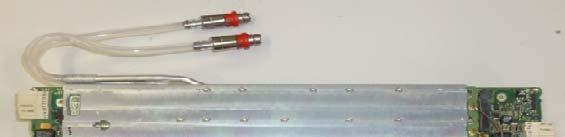
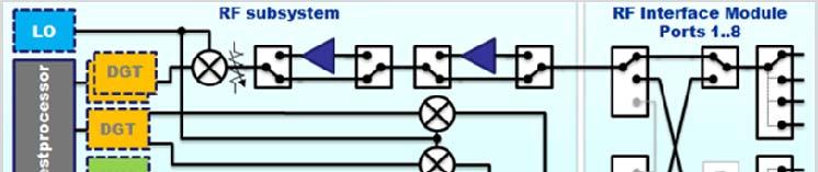
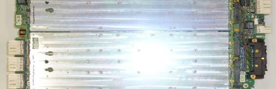
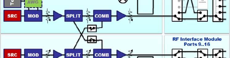
37 WSRF Card and RFIM Showing the 32 Ports WSRF Card RFIM WSRF Card RFIM /12/15 All Rights Reserved - ADVANTEST CORPORATION 37
38 Instruments spec improvement benefit testing TX Test Results Summary WSRF/MX vs Previous Generation IQ Phase stability TX EVM & ACLR (Band 01, 2xCCA, 20MHz-20MHz), BW=120MHz TX EVM & ACLR (Band 39, 1xCCA, 20MHz), BW=60MHz CIM3 compared with LAB s MXA RF and Baseband IQ test Previous Generation Limited by digitizer's uncertainty 5ns Limited by instrument BW (~22MHz) 24 captures (6 captures/test mode x 4 modes) Limited by instrument BW (~22MHz) 12 captures (3 captures/test mode x 4 modes) Limited by digitizer noise floor Need to test RF and BB separately (resource limitation) WSRF/MX WSMX uncertainty is only 300ps Up to 200MHz BW 4 captures (1 captures/test mode x 4 modes) Up to 200MHz BW 4 captures (1 captures/test mode x 4 modes) Better noise floor Able to do RF and BB measurement in parallel 2017/12/15 All Rights Reserved - ADVANTEST CORPORATION 38
39 Operating Sequence An operating sequence is an arrangement of calls of patterns, actions, and transaction sequences to be executed. The arrangement can be serial, parallel, or a combination of both. sequential { actioncall DC; parallel { sequential {actioncall AWG; } sequential { transactioncall Condition1; parallel { sequential{actioncall meas1porta; } sequential{actioncall meas1portb; } } } } } DC Mixed PA RF RF Straightforward and descriptive All domains supported Precise synchronization 2017/12/15 All Rights Reserved - ADVANTEST CORPORATION 39

40 SmarTest 8 Key Features Operating Sequence Protocol DGT capture RF stim Easy to program with using Device Setup API In previous test program, there are 27 RX BASIC Test Suites (27 RX Path) In WSRF, we can test all 27 test suites in one test suite Multiple test suites can be combined with Operating Sequence to save test time Stop point can be set in the Operating Sequence during debugging Easy to debug with using Spectrum Analyzer or Oscilloscope No need to modify any codes 2017/12/15 All Rights Reserved - ADVANTEST CORPORATION 40
41 Site Interlacing In case of limit resources, Site Interlacing is automatically arranged Site Interlacing is based on DUT board description. PA PA PA PA RF power site 1&5 RF power RF power RF power site 2&6 site 3&7 RF power Independent resources site 4&8 RF power Shared resources 2017/12/15 All Rights Reserved - ADVANTEST CORPORATION 41
42 RF transceiver LTE CAT 10, traditional serial test flow (shared source architecture) BB measure IQ BB stim IQ BB measure IQ BB stim IQ Site 1 Site 8 A B C x M Y A B C x M Y RF stim RF measure RF stim RF measure A B C x M Y Test time 2017/12/15 All Rights Reserved - ADVANTEST CORPORATION 41
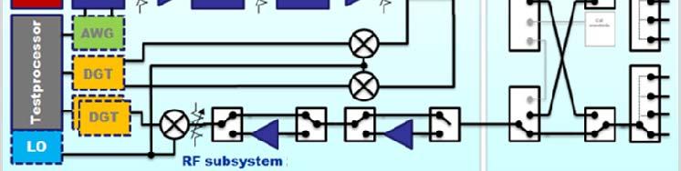
43 RF transceiver LTE CAT 10, choice for max parallelism (independent RF subsystem architecture) BB measure IQ A B C RF stim BB stim IQ Site 1 x M Y RF measure BB measure IQ A B C RF stim BB stim IQ Site 8 x M Y RF measure Parallel RF test flow Y M x C B Test time benefit by architecture t Serial RF test flow A B C x M Y Test time 2017/12/15 All Rights Reserved - ADVANTEST CORPORATION 42


44 Architectural differences LTE-A CAT 10 Transceiver 3 DL / 2 UL Shared stim source vs independent RF subsystem A B C RF architecture based on a fanout architecture with shared stim sources RF architecture based on independent RF subsystems and true parallel stim / measure ports M Y X misc f Traditional ATE shared source architecture A B M Y x C WSRF Y M x C B A FDD Test time benefit by architecture t Engineering efficiency Faster TTM SmarTest 8 and WSRF architecture Improved fault coverage Mission mode parallelism spurs, harmonics,... Test time benefits Higher parallelism shorter test time 2017/12/15 All Rights Reserved - ADVANTEST CORPORATION 43
45 WSRF Brief Introduction 2017/12/15 All Rights Reserved - ADVANTEST CORPORATION 45


46 Performance RF Performance: Frequency coverage: 10 MHz 6 GHz RX Bandwidth: 200 MHz, 350 MHz (undersampling) TX Modulated Bandwidth: 200MHz Dynamic range: 145 db Settling Time Frequency change us Power change - 80 us SmarTest 8: TTQ and early competitive throughput Consistent, intuitive, test oriented ( instruments ), debug, & reuse Operating sequence: actions (synced with digital, DPS, MX, RF) Unified tools, GUIs and APIs for digital, DC, analog, and RF Auto handling of Upload + Background processing ac 160MHz signal 5.8GHz 1024 QAM 0.55% EVM Up to 200 MHz bandwidth 2017/12/15 All Rights Reserved - ADVANTEST CORPORATION 45
47 WSMX Brief Introduction 2017/12/15 All Rights Reserved - ADVANTEST CORPORATION 47
48 Architecture A Wave Scale MX card consists of 32 instruments contained in 16 HW Units High Speed Unit: High Speed AWG High Speed Digitizer High Resolution Unit: High Resolution AWG High Resolution Digitizer PMU Per Pogo Test Processor Controlled Synchronization Large Memory Pool Hardware Signal Processing Unit (SPU) 32 instruments per card 16 Units per Wave Scale MX card All can be used in parallel, independent, full pattern controlled 64 bidirectional analog pogos incl. PMU 2017/12/15 All Rights Reserved - Advantest Corporation 48
49 Wave Scale MX Key Values 4x density, 32 parallel instruments All 32 instruments are fully independent All functionality is sequencer controlled, no trigger pins, exact repeatablity Flexibility via licensing of units Dramatically simplified use-model (SmarTest 8) ) Overall improved performance Larger and flexible memory 216 Msamples shared btw. 4 instruments (Digitizer) All pogos can be connected to either AWG or Digitizer (bidirectional) Flexible I/O Matrix for simplified loadboard design PMU per pogo No dedicated analog calibration equipment needed Except in case of tight IQ requirements 2017/12/15 All Rights Reserved - ADVANTEST CORPORATION 48
50 Summary Wider bandwidth on WSRF (200MHz) Better & more user friendly software (SmarTest 8) Easier to burst test together (Operating Sequence) Operating sequence debug with stop point Multisite data handling Measurement stability Very good SDEV across all tests Good repeatability No averaging needed WSMX better noise floor Minimum effort on test time reduction (TTR) Outstanding COT 2017/12/15 All Rights Reserved - ADVANTEST CORPORATION 50
51 谢谢 2017/12/15 All Rights Reserved - ADVANTEST CORPORATION 51
ADI 2006 RF Seminar. Chapter II RF/IF Components and Specifications for Receivers
 ADI 2006 RF Seminar Chapter II RF/IF Components and Specifications for Receivers 1 RF/IF Components and Specifications for Receivers Fixed Gain and Variable Gain Amplifiers IQ Demodulators Analog-to-Digital
TSEK02: Radio Electronics Lecture 8: RX Nonlinearity Issues, Demodulation. Ted Johansson, EKS, ISY
 TSEK02: Radio Electronics Lecture 8: RX Nonlinearity Issues, Demodulation Ted Johansson, EKS, ISY RX Nonlinearity Issues: 2.2, 2.4 Demodulation: not in the book 2 RX nonlinearities System Nonlinearity
TSEK02: Radio Electronics Lecture 8: RX Nonlinearity Issues, Demodulation. Ted Johansson, EKS, ISY
 TSEK02: Radio Electronics Lecture 8: RX Nonlinearity Issues, Demodulation Ted Johansson, EKS, ISY 2 RX Nonlinearity Issues, Demodulation RX nonlinearities (parts of 2.2) System Nonlinearity Sensitivity
Reconfigurable 6 GHz Vector Signal Transceiver with I/Q Interface
 SPECIFICATIONS PXIe-5645 Reconfigurable 6 GHz Vector Signal Transceiver with I/Q Interface Contents Definitions...2 Conditions... 3 Frequency...4 Frequency Settling Time... 4 Internal Frequency Reference...
ADI 2006 RF Seminar. Chapter VI A Detailed Look at Wireless Signal Chain Architectures
 DI 2006 R Seminar Chapter VI Detailed Look at Wireless Chain rchitectures 1 Receiver rchitectures Receivers are designed to detect and demodulate the desired signal and remove unwanted blockers Receiver
TSEK38 Radio Frequency Transceiver Design: Project work B
 TSEK38 Project Work: Task specification A 1(15) TSEK38 Radio Frequency Transceiver Design: Project work B Course home page: Course responsible: http://www.isy.liu.se/en/edu/kurs/tsek38/ Ted Johansson (ted.johansson@liu.se)
RF/IF Terminology and Specs
 RF/IF Terminology and Specs Contributors: Brad Brannon John Greichen Leo McHugh Eamon Nash Eberhard Brunner 1 Terminology LNA - Low-Noise Amplifier. A specialized amplifier to boost the very small received
QUICK START GUIDE FOR DEMONSTRATION CIRCUIT 678A 40MHZ TO 900MHZ DIRECT CONVERSION QUADRATURE DEMODULATOR
 DESCRIPTION QUICK START GUIDE FOR DEMONSTRATION CIRCUIT 678A LT5517 Demonstration circuit 678A is a 40MHz to 900MHz Direct Conversion Quadrature Demodulator featuring the LT5517. The LT 5517 is a direct
Understanding RF and Microwave Analysis Basics
 Understanding RF and Microwave Analysis Basics Kimberly Cassacia Product Line Brand Manager Keysight Technologies Agenda µw Analysis Basics Page 2 RF Signal Analyzer Overview & Basic Settings Overview
PXIe Contents SPECIFICATIONS. 14 GHz and 26.5 GHz Vector Signal Analyzer
 SPECIFICATIONS PXIe-5668 14 GHz and 26.5 GHz Vector Signal Analyzer These specifications apply to the PXIe-5668 (14 GHz) Vector Signal Analyzer and the PXIe-5668 (26.5 GHz) Vector Signal Analyzer with
Keysight Technologies 8 Hints for Making Better Measurements Using RF Signal Generators. Application Note
 Keysight Technologies 8 Hints for Making Better Measurements Using RF Signal Generators Application Note 02 Keysight 8 Hints for Making Better Measurements Using RF Signal Generators - Application Note
Receiver Architecture
 Receiver Architecture Receiver basics Channel selection why not at RF? BPF first or LNA first? Direct digitization of RF signal Receiver architectures Sub-sampling receiver noise problem Heterodyne receiver
MEASURING HUM MODULATION USING MATRIX MODEL HD-500 HUM DEMODULATOR
 MEASURING HUM MODULATION USING MATRIX MODEL HD-500 HUM DEMODULATOR The SCTE defines hum modulation as, The amplitude distortion of a signal caused by the modulation of the signal by components of the power
A balancing act: Envelope Tracking and Digital Pre-Distortion in Handset Transmitters
 Abstract Envelope tracking requires the addition of another connector to the RF power amplifier. Providing this supply modulation input leads to many possibilities for improving the performance of the
Keysight Technologies Making Accurate Intermodulation Distortion Measurements with the PNA-X Network Analyzer, 10 MHz to 26.5 GHz
 Keysight Technologies Making Accurate Intermodulation Distortion Measurements with the PNA-X Network Analyzer, 10 MHz to 26.5 GHz Application Note Overview This application note describes accuracy considerations
Testing RFIC Power Amplifiers with Envelope Tracking. April 2014
 Testing RFIC Power Amplifiers with Envelope Tracking April 2014 1 Agenda Key Test Challenges Addressing Test Challenges New emerging technologies such as envelope tracking and DPD and their implications
26.8: A 1.9GHz Single-Chip CMOS PHS Cellphone
 26.8: A 1.9GHz Single-Chip CMOS PHS Cellphone William W. Si, Srenik Mehta, Hirad Samavati, Manolis Terrovitis, Michael Mack, KeithOnodera, SteveJen, Susan Luschas, Justin Hwang, SuniMendis, DavidSu, BruceWooley
 HF Receiver Testing: Issues & Advances (also presented at APDXC 2014, Osaka, Japan, November 2014) Adam Farson VA7OJ Copyright 2014 North Shore Amateur Radio Club NSARC HF Operators HF RX Testing 1 HF
Measuring Non-linear Amplifiers
 Measuring Non-linear Amplifiers Transceiver Components & Measuring Techniques MM3 Jan Hvolgaard Mikkelsen Radio Frequency Integrated Systems and Circuits Division Aalborg University 27 Agenda Non-linear
Keysight Technologies
 Keysight Technologies Generating Signals Basic CW signal Block diagram Applications Analog Modulation Types of analog modulation Block diagram Applications Digital Modulation Overview of IQ modulation
Understanding Low Phase Noise Signals. Presented by: Riadh Said Agilent Technologies, Inc.
 Understanding Low Phase Noise Signals Presented by: Riadh Said Agilent Technologies, Inc. Introduction Instabilities in the frequency or phase of a signal are caused by a number of different effects. Each
HF Receivers, Part 2
 HF Receivers, Part 2 Superhet building blocks: AM, SSB/CW, FM receivers Adam Farson VA7OJ View an excellent tutorial on receivers NSARC HF Operators HF Receivers 2 1 The RF Amplifier (Preamp)! Typical
A 1.9GHz Single-Chip CMOS PHS Cellphone
 A 1.9GHz Single-Chip CMOS PHS Cellphone IEEE JSSC, Vol. 41, No.12, December 2006 William Si, Srenik Mehta, Hirad Samavati, Manolis Terrovitis, Michael Mack, Keith Onodera, Steve Jen, Susan Luschas, Justin
TestData Summary of 5.2GHz WLAN Direct Conversion RF Transceiver Board
 Page 1 of 16 ========================================================================================= TestData Summary of 5.2GHz WLAN Direct Conversion RF Transceiver Board =========================================================================================
Bridging the Gap between System & Circuit Designers
 Bridging the Gap between System & Circuit Designers October 27, 2004 Presented by: Kal Kalbasi Q & A Marc Petersen Copyright 2003 Agilent Technologies, Inc. The Gap System Communication System Design System
PTX-0350 RF UPCONVERTER, MHz
 PTX-0350 RF UPCONVERTER, 300 5000 MHz OPERATING MODES I/Q upconverter RF = LO + IF upconverter RF = LO - IF upconverter Synthesizer 10 MHz REFERENCE INPUT/OUTPUT EXTERNAL LOCAL OSCILLATOR INPUT I/Q BASEBAND
Keysight Technologies PNA-X Series Microwave Network Analyzers
 Keysight Technologies PNA-X Series Microwave Network Analyzers Active-Device Characterization in Pulsed Operation Using the PNA-X Application Note Introduction Vector network analyzers (VNA) are the common
PARAMETER CONDITIONS TYPICAL PERFORMANCE Operating Supply Voltage 3.1V to 3.5V Supply Current V CC = 3.3V, LO applied 152mA
 DESCRIPTION LT5578 Demonstration circuit 1545A-x is a high linearity upconverting mixer featuring the LT5578. The LT 5578 is a high performance upconverting mixer IC optimized for output frequencies in
Multi-Signal, Multi-Format Analysis With Agilent VSA Software
 Multi-Signal, Multi-Format Analysis With Agilent 89600 VSA Software Ken Voelker Agilent Technologies Inc. April 2012 1 April, 25 2012 Agenda Introduction: New Measurement Challenges Multi-Measurements
RADIO RECEIVERS ECE 3103 WIRELESS COMMUNICATION SYSTEMS
 RADIO RECEIVERS ECE 3103 WIRELESS COMMUNICATION SYSTEMS FUNCTIONS OF A RADIO RECEIVER The main functions of a radio receiver are: 1. To intercept the RF signal by using the receiver antenna 2. Select the
8 Hints for Better Spectrum Analysis. Application Note
 8 Hints for Better Spectrum Analysis Application Note 1286-1 The Spectrum Analyzer The spectrum analyzer, like an oscilloscope, is a basic tool used for observing signals. Where the oscilloscope provides
Radio Research Directions. Behzad Razavi Communication Circuits Laboratory Electrical Engineering Department University of California, Los Angeles
 Radio Research Directions Behzad Razavi Communication Circuits Laboratory Electrical Engineering Department University of California, Los Angeles Outline Introduction Millimeter-Wave Transceivers - Applications
22 Marzo 2012 IFEMA, Madrid spain.ni.com/nidays.
 22 Marzo 2012 IFEMA, Madrid spain.ni.com/nidays www.infoplc.net The Art of Benchmarking Speed PXI Versus Rack-and-Stack Test Equipment Filippo Persia Systems Engineer Automated Test Mediterranean Region
PN9000 PULSED CARRIER MEASUREMENTS
 The specialist of Phase noise Measurements PN9000 PULSED CARRIER MEASUREMENTS Carrier frequency: 2.7 GHz - PRF: 5 khz Duty cycle: 1% Page 1 / 12 Introduction When measuring a pulse modulated signal the
Addressing the Challenges of Wideband Radar Signal Generation and Analysis. Marco Vivarelli Digital Sales Specialist
 Addressing the Challenges of Wideband Radar Signal Generation and Analysis Marco Vivarelli Digital Sales Specialist Agenda Challenges of Wideband Signal Generation Challenges of Wideband Signal Analysis
General configuration
 Transmitter General configuration In some cases the modulator operates directly at the transmission frequency (no up conversion required) In digital transmitters, the information is represented by the
Receiver Design. Prof. Tzong-Lin Wu EMC Laboratory Department of Electrical Engineering National Taiwan University 2011/2/21
 Receiver Design Prof. Tzong-Lin Wu EMC Laboratory Department of Electrical Engineering National Taiwan University 2011/2/21 MW & RF Design / Prof. T. -L. Wu 1 The receiver mush be very sensitive to -110dBm
TETRA Tx Test Solution
 Product Introduction TETRA Tx Test Solution Signal Analyzer Reference Specifications ETSI EN 300 394-1 V3.3.1(2015-04) / Part1: Radio ETSI TS 100 392-2 V3.6.1(2013-05) / Part2: Air Interface May. 2016
Characterization and Compensation of Non-Linear Effects in Components. Dr. Florian Ramian
 Characterization and Compensation of Non-Linear Effects in Components Dr. Florian Ramian Agenda ı Introduction: What Is a Non-Linear Device ı Characterization of Non-Linear Devices Characterization Parameters
SC5407A/SC5408A 100 khz to 6 GHz RF Upconverter. Datasheet. Rev SignalCore, Inc.
 SC5407A/SC5408A 100 khz to 6 GHz RF Upconverter Datasheet Rev 1.2 2017 SignalCore, Inc. support@signalcore.com P R O D U C T S P E C I F I C A T I O N S Definition of Terms The following terms are used
TSEK38: Radio Frequency Transceiver Design Lecture 7: Receiver Synthesis (II)
") TSEK38: Radio Frequency Transceiver Design Lecture 7: Receiver Synthesis (II) Ted Johansson, ISY ted.johansson@liu.se Systematic Receiver Synthesis (II) 4.3 Intermodulation characteristics Phase noise
TSEK38: Radio Frequency Transceiver Design Lecture 7: Receiver Synthesis (II) Ted Johansson, ISY ted.johansson@liu.se Systematic Receiver Synthesis (II) 4.3 Intermodulation characteristics Phase noise
Analog Devices Welcomes Hittite Microwave Corporation NO CONTENT ON THE ATTACHED DOCUMENT HAS CHANGED
 Analog Devices Welcomes Hittite Microwave Corporation NO CONTENT ON THE ATTACHED DOCUMENT HAS CHANGED www.analog.com www.hittite.com THIS PAGE INTENTIONALLY LEFT BLANK v01.05.00 HMC141/142 MIXER OPERATION
3250 Series Spectrum Analyzer
 The most important thing we build is trust ADVANCED ELECTRONIC SOLUTIONS AVIATION SERVICES COMMUNICATIONS AND CONNECTIVITY MISSION SYSTEMS 3250 Series Spectrum Analyzer > Agenda Introduction
RF Fundamentals Part 2 Spectral Analysis
 Spectral Analysis Dec 8, 2016 Kevin Nguyen Keysight Technologies Agenda Overview Theory of Operation Traditional Spectrum Analyzers Modern Signal Analyzers Specifications Features Wrap-up Page 2 Overview
Utilizzo del Time Domain per misure EMI
 Utilizzo del Time Domain per misure EMI Roberto Sacchi Measurement Expert Manager - Europe 7 Giugno 2017 Compliance EMI receiver requirements (CISPR 16-1-1 ) range 9 khz - 18 GHz: A normal +/- 2 db absolute
Reflection EVM Impairments in Wideband 60GHz and E band designs
 Reflection EVM Impairments in Wideband 60GHz and E band designs Dror Regev About Presto Engineering Leader in Integrated Test & Product Engineering and Back-end Production services Service hubs in USA,
Introduction to Surface Acoustic Wave (SAW) Devices
 Devices") May 31, 2018 Introduction to Surface Acoustic Wave (SAW) Devices Part 7: Basics of RF Circuits Ken-ya Hashimoto Chiba University k.hashimoto@ieee.org http://www.te.chiba-u.jp/~ken Contents Noise Figure
May 31, 2018 Introduction to Surface Acoustic Wave (SAW) Devices Part 7: Basics of RF Circuits Ken-ya Hashimoto Chiba University k.hashimoto@ieee.org http://www.te.chiba-u.jp/~ken Contents Noise Figure
SSB0260A Single Sideband Mixer GHz
 Single Sideband Mixer.2 6. GHz FEATURES LO/RF Frequency: Input IP3: Sideband Suppression: LO Leakage: LO Power: DC Power:.2 6. GHz +32 dbm -45 dbc (Typical) -5 dbm (Typical) -1 to +1 dbm +5V @ 5 ma DESCRIPTION
HP Archive. This vintage Hewlett Packard document was preserved and distributed by www. hparchive.com Please visit us on the web!
 HP Archive This vintage Hewlett Packard document was preserved and distributed by www. hparchive.com Please visit us on the web! On-line curator: Glenn Robb This document is for FREE distribution only!
Pulsed VNA Measurements:
 Pulsed VNA Measurements: The Need to Null! January 21, 2004 presented by: Loren Betts Copyright 2004 Agilent Technologies, Inc. Agenda Pulsed RF Devices Pulsed Signal Domains VNA Spectral Nulling Measurement
RF, Microwave & Wireless. All rights reserved
 RF, Microwave & Wireless All rights reserved 1 Non-Linearity Phenomenon All rights reserved 2 Physical causes of nonlinearity Operation under finite power-supply voltages Essential non-linear characteristics
An All CMOS, 2.4 GHz, Fully Adaptive, Scalable, Frequency Hopped Transceiver
 An All CMOS, 2.4 GHz, Fully Adaptive, Scalable, Frequency Hopped Transceiver Farbod Behbahani John Leete Alexandre Kral Shahrzad Tadjpour Karapet Khanoyan Paul J. Chang Hooman Darabi Maryam Rofougaran
Radio Receiver Architectures and Analysis
 Radio Receiver Architectures and Analysis Robert Wilson December 6, 01 Abstract This article discusses some common receiver architectures and analyzes some of the impairments that apply to each. 1 Contents
Exploring Trends in Technology and Testing in Satellite Communications
 Exploring Trends in Technology and Testing in Satellite Communications Aerospace Defense Symposium Giuseppe Savoia Keysight Technologies Agenda Page 2 Evolving military and commercial satellite communications
Data Sheet SC5317 & SC5318A. 6 GHz to 26.5 GHz RF Downconverter SignalCore, Inc. All Rights Reserved
 Data Sheet SC5317 & SC5318A 6 GHz to 26.5 GHz RF Downconverter www.signalcore.com 2018 SignalCore, Inc. All Rights Reserved Definition of Terms 1 Table of Contents 1. Definition of Terms... 2 2. Description...
SC5307A/SC5308A 100 khz to 6 GHz RF Downconverter. Datasheet SignalCore, Inc.
 SC5307A/SC5308A 100 khz to 6 GHz RF Downconverter Datasheet 2017 SignalCore, Inc. support@signalcore.com P RODUCT S PECIFICATIONS Definition of Terms The following terms are used throughout this datasheet
Today s mobile devices
 PAGE 1 NOVEMBER 2013 Highly Integrated, High Performance Microwave Radio IC Chipsets cover 6-42 GHz Bands Complete Upconversion & Downconversion Chipsets for Microwave Point-to-Point Outdoor Units (ODUs)
60 GHz Receiver (Rx) Waveguide Module
 Waveguide Module") The PEM is a highly integrated millimeter wave receiver that covers the GHz global unlicensed spectrum allocations packaged in a standard waveguide module. Receiver architecture is a double conversion,
The PEM is a highly integrated millimeter wave receiver that covers the GHz global unlicensed spectrum allocations packaged in a standard waveguide module. Receiver architecture is a double conversion,
Advanced RF Measurements You Didn t Know Your Oscilloscope Could Make. Brad Frieden Philip Gresock
 Advanced RF Measurements You Didn t Know Your Oscilloscope Could Make Brad Frieden Philip Gresock Agenda RF measurement challenges Oscilloscope platform overview Typical RF characteristics Bandwidth vs.
60 GHz RX. Waveguide Receiver Module. Features. Applications. Data Sheet V60RXWG3. VubIQ, Inc
 GHz RX VRXWG Features Complete millimeter wave receiver WR-, UG-8/U flange Operates in the to GHz unlicensed band db noise figure Up to.8 GHz modulation bandwidth I/Q analog baseband interface Integrated
Wideband Receiver for Communications Receiver or Spectrum Analysis Usage: A Comparison of Superheterodyne to Quadrature Down Conversion
 A Comparison of Superheterodyne to Quadrature Down Conversion Tony Manicone, Vanteon Corporation There are many different system architectures which can be used in the design of High Frequency wideband
PXI LTE FDD and LTE TDD Measurement Suites Data Sheet
 PXI LTE FDD and LTE TDD Measurement Suites Data Sheet The most important thing we build is trust A production ready ATE solution for RF alignment and performance verification UE Tx output power Transmit
PXIe Contents CALIBRATION PROCEDURE. Reconfigurable 6 GHz RF Vector Signal Transceiver with 200 MHz Bandwidth
 IBRATION PROCEDURE PXIe-5646 Reconfigurable 6 GHz Vector Signal Transceiver with 200 MHz Bandwidth This document contains the verification and adjustment procedures for the PXIe-5646 vector signal transceiver.
A COMPACT, AGILE, LOW-PHASE-NOISE FREQUENCY SOURCE WITH AM, FM AND PULSE MODULATION CAPABILITIES
 A COMPACT, AGILE, LOW-PHASE-NOISE FREQUENCY SOURCE WITH AM, FM AND PULSE MODULATION CAPABILITIES Alexander Chenakin Phase Matrix, Inc. 109 Bonaventura Drive San Jose, CA 95134, USA achenakin@phasematrix.com
Keywords: GPS, receiver, GPS receiver, MAX2769, 2769, 1575MHz, Integrated GPS Receiver, Global Positioning System
 Maxim > Design Support > Technical Documents > User Guides > APP 3910 Keywords: GPS, receiver, GPS receiver, MAX2769, 2769, 1575MHz, Integrated GPS Receiver, Global Positioning System USER GUIDE 3910 User's
Advances in RF and Microwave Measurement Technology
 1 Advances in RF and Microwave Measurement Technology Rejwan Ali Marketing Engineer NI Africa and Oceania New Demands in Modern RF and Microwave Test In semiconductor and wireless, technologies such as
8 Hints for Better Spectrum Analysis. Application Note
 8 Hints for Better Spectrum Analysis Application Note 1286-1 The Spectrum Analyzer The spectrum analyzer, like an oscilloscope, is a basic tool used for observing signals. Where the oscilloscope provides
A New Look at SDR Testing
 A New Look at SDR Testing (presented at SDR Academy 2016, Friedrichshafen, Germany) Adam Farson VA7OJ/AB4OJ Copyright 2016 A. Farson VA7OJ/AB4OJ 25-Dec-17 SDR Academy 2016 - SDR Testing 1 Performance issues
Satellite Communications: Part 4 Signal Distortions & Errors and their Relation to Communication Channel Specifications. Howard Hausman April 1, 2010
 Satellite Communications: Part 4 Signal Distortions & Errors and their Relation to Communication Channel Specifications Howard Hausman April 1, 2010 Satellite Communications: Part 4 Signal Distortions
MAKING TRANSIENT ANTENNA MEASUREMENTS
 MAKING TRANSIENT ANTENNA MEASUREMENTS Roger Dygert, Steven R. Nichols MI Technologies, 1125 Satellite Boulevard, Suite 100 Suwanee, GA 30024-4629 ABSTRACT In addition to steady state performance, antennas
QUICK START GUIDE FOR DEMONSTRATION CIRCUIT 1455A 5MHZ TO 1600MHZ HIGH LINEARITY DIRECT QUADRATURE MODULATOR LTC5598 DESCRIPTION
 LTC5598 DESCRIPTION Demonstration circuit 1455A is a high linearity direct quadrature modulator featuring the LTC5598. The LTC 5598 is a direct I/Q modulator designed for high performance wireless applications,
Technician License Course Chapter 3 Types of Radios and Radio Circuits. Module 7
 Technician License Course Chapter 3 Types of Radios and Radio Circuits Module 7 Radio Block Diagrams Radio Circuits can be shown as functional blocks connected together. Knowing the description of common
Advances in RF and Microwave Measurement Technology
 1 Advances in RF and Microwave Measurement Technology Chi Xu Certified LabVIEW Architect Certified TestStand Architect New Demands in Modern RF and Microwave Test In semiconductor and wireless, technologies
Improving Amplitude Accuracy with Next-Generation Signal Generators
 Improving Amplitude Accuracy with Next-Generation Signal Generators Generate True Performance Signal generators offer precise and highly stable test signals for a variety of components and systems test
PXI LTE/LTE-A Downlink (FDD and TDD) Measurement Suite Data Sheet
 Measurement Suite Data Sheet") PXI LTE/LTE-A Downlink (FDD and TDD) Measurement Suite Data Sheet The most important thing we build is trust Designed for the production test of the base station RF, tailored for the evolving small cell
PXI LTE/LTE-A Downlink (FDD and TDD) Measurement Suite Data Sheet The most important thing we build is trust Designed for the production test of the base station RF, tailored for the evolving small cell
Understanding Probability of Intercept for Intermittent Signals
 2013 Understanding Probability of Intercept for Intermittent Signals Richard Overdorf & Rob Bordow Agilent Technologies Agenda Use Cases and Signals Time domain vs. Frequency Domain Probability of Intercept
SmartSpice RF Harmonic Balance Based and Shooting Method Based RF Simulation
 SmartSpice RF Harmonic Balance Based and Shooting Method Based RF Simulation Silvaco Overview SSRF Attributes Harmonic balance approach to solve system of equations in frequency domain Well suited for
2012 LitePoint Corp LitePoint, A Teradyne Company. All rights reserved.
 LTE TDD What to Test and Why 2012 LitePoint Corp. 2012 LitePoint, A Teradyne Company. All rights reserved. Agenda LTE Overview LTE Measurements Testing LTE TDD Where to Begin? Building a LTE TDD Verification
Receiver Architectures
 83080RA/1 Receiver Architectures Markku Renfors Tampere University of Technology Digital Media Institute/Telecommunications 83080RA/2 Topics 1. Main analog components for receivers - amplifiers - filters
Techniques for Characterizing Spurious Signals
 Techniques for Characterizing Spurious Signals October 21, 2014 Riadh Said Product Manager Microwave and Communications Division Keysight Technologies Our Goals today Review the sweep time equation to
How do I optimize desired Amplifier Specifications?
 How do I optimize desired Amplifier Specifications? PAE (accuracy
TRANSCOM Manufacturing & Education
 www.transcomwireless.com 1 G6 Vector Signal Generator Overview G6 Vector Signal Generator is a high performance vector signal generator. It can generate arbitrary wave signal, continuous wave signal, common
ELEN 701 RF & Microwave Systems Engineering. Lecture 4 October 11, 2006 Dr. Michael Thorburn Santa Clara University
 ELEN 7 RF & Microwave Systems Engineering Lecture 4 October, 26 Dr. Michael Thorburn Santa Clara University Lecture 5 Receiver System Analysis and Design, Part II Key Parameters Intermodulation Characteristics
Introduction to Receivers
 Introduction to Receivers Purpose: translate RF signals to baseband Shift frequency Amplify Filter Demodulate Why is this a challenge? Interference Large dynamic range required Many receivers must be capable
DMR Tx Test Solution. Signal Analyzer MS2830A. Reference Specifications
 Product Introduction DMR Tx Test Solution Signal Analyzer MS2830A Reference Specifications ETSI EN 300 113 Version 2.1.1 (2016-08) / Technical characteristics of the transmitter ETSI TS 102 361-1 Version
APPLICATION NOTE 3942 Optimize the Buffer Amplifier/ADC Connection
 Maxim > Design Support > Technical Documents > Application Notes > Communications Circuits > APP 3942 Maxim > Design Support > Technical Documents > Application Notes > High-Speed Interconnect > APP 3942
Analog Devices Welcomes Hittite Microwave Corporation NO CONTENT ON THE ATTACHED DOCUMENT HAS CHANGED
 Analog Devices Welcomes Hittite Microwave Corporation NO CONTENT ON THE ATTACHED DOCUMENT HAS CHANGED www.analog.com www.hittite.com THIS PAGE INTENTIONALLY LEFT BLANK 17 Product Application Notes Introduction
Agilent Highly Accurate Amplifier ACLR and ACPR Testing with the Agilent N5182A MXG Vector Signal Generator. Application Note
 Agilent Highly Accurate Amplifier ACLR and ACPR Testing with the Agilent N5182A MXG Vector Signal Generator Application Note Introduction 1 0 0 1 Symbol encoder I Q Baseband filters I Q IQ modulator Other
Berkeley Nucleonics Corporation
 Berkeley Nucleonics Corporation A trusted source for quality and innovative instrumentation since 1963 Test And Measurement Nuclear Expertise RF/Microwave BNC at Our Core BNC Mission: Providing our customers
RF and Microwave Test and Design Roadshow 5 Locations across Australia and New Zealand
 RF and Microwave Test and Design Roadshow 5 Locations across Australia and New Zealand Advanced VNA Measurements Agenda Overview of the PXIe-5632 Architecture SW Experience Overview of VNA Calibration
High Dynamic Range Receiver Parameters
 High Dynamic Range Receiver Parameters The concept of a high-dynamic-range receiver implies more than an ability to detect, with low distortion, desired signals differing, in amplitude by as much as 90
3GPP Radio Prototyping Using Radio420X. Technical Article. 3GPP Radio Prototyping Using Radio420X. nutaq.com
 Technical Article 3GPP Radio Prototyping Using Radio420X 1 3GPP Radio Prototyping Using Radio420X Written by M. Ahmed Ouameur, PhD, MBA Abstract This application note addresses 3GPP radio design and prototyping
The best radio for worst events. Over HF links. Hana Rafi - CEO Eder Yehuda - VP R&D
 MOBAT MICOM The best radio for worst events Increasing Data Throughput Over HF links Hana Rafi - CEO Eder Yehuda - VP R&D 1 Traditional HF Radio -Analog voice & 50,75 bps New Trends on HF - Digital voice,
Does The Radio Even Matter? - Transceiver Characterization Testing Framework
 Does The Radio Even Matter? - Transceiver Characterization Testing Framework TRAVIS COLLINS, PHD ROBIN GETZ 2017 Analog Devices, Inc. All rights reserved. 1 Which cost least? 3 2017 Analog Devices, Inc.
THE BASICS OF RADIO SYSTEM DESIGN
 THE BASICS OF RADIO SYSTEM DESIGN Mark Hunter * Abstract This paper is intended to give an overview of the design of radio transceivers to the engineer new to the field. It is shown how the requirements
ELEN 701 RF & Microwave Systems Engineering. Lecture 8 November 8, 2006 Dr. Michael Thorburn Santa Clara University
 ELEN 701 RF & Microwave Systems Engineering Lecture 8 November 8, 2006 Dr. Michael Thorburn Santa Clara University System Noise Figure Signal S1 Noise N1 GAIN = G Signal G x S1 Noise G x (N1+No) Self Noise
HF Receivers, Part 3
 HF Receivers, Part 3 Introduction to frequency synthesis; ancillary receiver functions Adam Farson VA7OJ View an excellent tutorial on receivers Another link to receiver principles NSARC HF Operators HF
TESTING METHODS AND ERROR BUDGET ANALYSIS OF A SOFTWARE DEFINED RADIO By Richard Overdorf
 TESTING METHODS AND ERROR BUDGET ANALYSIS OF A SOFTWARE DEFINED RADIO By Richard Overdorf SDR Considerations Data rates Voice Image Data Streaming Video Environment Distance Terrain High traffic/low traffic
Session 3. CMOS RF IC Design Principles
 Session 3 CMOS RF IC Design Principles Session Delivered by: D. Varun 1 Session Topics Standards RF wireless communications Multi standard RF transceivers RF front end architectures Frequency down conversion
SmartSpice RF Harmonic Balance Based RF Simulator. Advanced RF Circuit Simulation
 SmartSpice RF Harmonic Balance Based RF Simulator Advanced RF Circuit Simulation SmartSpice RF Overview Uses harmonic balance approach to solve system equations in frequency domain Well suited for RF and