SmartSpice RF Harmonic Balance Based and Shooting Method Based RF Simulation
|
|
|
- Geoffrey Warren
- 5 years ago
- Views:
Transcription

1 SmartSpice RF Harmonic Balance Based and Shooting Method Based RF Simulation
2 Silvaco Overview SSRF Attributes Harmonic balance approach to solve system of equations in frequency domain Well suited for RF and Microwave Circuits as they are naturally handled in frequency domain Time domain shooting method to determine steady state response Shooting method can be preferable to HB for the strongly nonlinear circuits, consist mostly of time-dependent elements - 2 -

3 Silvaco Fills the Gap Linear Nonlinearity Digital Microwave 4 5 GHz Harmonic Balance Increasing Frequency RF 500MHz 5GHz Conventional Analog III-V Material Silvaco SmartSpice Shooting Method CMOS Bipolar BiCMOS Oscillators, mixers, samplers, - 3 -
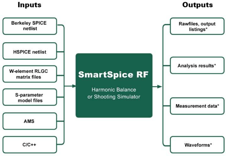
4 Silvaco Inputs/Outputs - 4 -


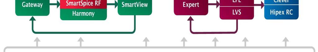
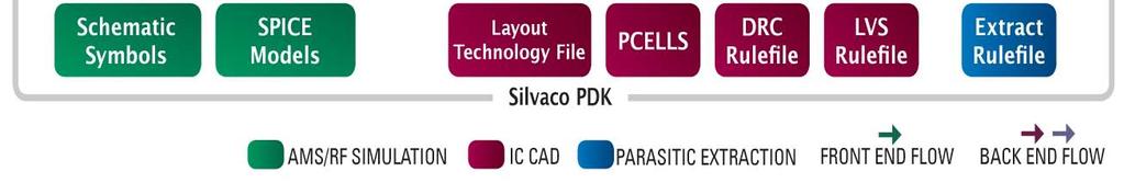
5 Silvaco RF Design Flow with RF PDK - 5 -
6 Silvaco Analysis SmartSpice RF incorporates the following analyses:.harmonic Periodic Steady State Analysis.HAC Periodic Steady State AC Analysis.HTF Periodic Steady State Transfer Function Analysis.HNET Periodic Steady State NET Analysis.HNOISE Periodic Steady State Noise Analysis.HOSCIL Periodic Steady State Analysis for autonomous circuits oscillators.spectral Quasi- Periodic Steady State Analysis.SPAC Quasi- Periodic Steady State AC Analysis.SPTF Quasi- Periodic Steady State Transfer Function Analysis.SPNET Quasi- Periodic Steady State NET Analysis.SPNOISE Quasi- Periodic Steady State Noise Analysis.ENV Circuit Envelope Analysis - 6 -
7 .HARMONIC (Periodic Steady State Analysis) Harmonic Balance Method Frequency-domain non-linear simulation techniques Shooting Method Transient analysis with periodicity constraint v(0) = v(t) Optimal convergence for simulation Provides a complete set of interactive control parameters Spectral-Newton, Continuation, and GMRES solvers Parameter Sweep Power or Frequency Sweep Computes 1db Compression Point (P1dB), 3rd Order Intercept Point (IP3) Monte-Carlo Analysis Embedded in each Silvaco analysis Unique ability for statistical distribution of gain, power, etc
8 Silvaco Small Signal Analyses.HTF Periodic Steady State Transfer Function Analysis Transfer functions from any input to a single output Any input from any image Applications: Conversion gain, image and sideband rejection, power supply rejection.hac Periodic Steady State AC Analysis Transfer functions from a single input to any output Any output at any sideband Applications: Conversion gain, intermodulation distortion.hnoise Periodic Steady State Noise Analysis Applications: Noise figure of mixers, phase noise of oscillators, noise of SC-filters & sample-and-holds - 8 -
9 Silvaco Small Signal Analyses.HNET Periodic Steady State NET Analysis Computes s-parameters for 2-port circuits that exhibit frequency translation 2-port linear noise option Capability to plot Rectangular Chart, Smith Chart, Noise/Gain/Stability circles. Useful for impedance matching, tuning, and optimization - 9 -
10 .HTF (Periodic Steady State Transfer Function Analysis) Single output, multiple input frequencies Conversion gain Image and sideband rejection Supply rejection LO feed-through Input Output LO Sideband index is relative to output frequency
11 .HAC (Periodic Steady State AC Analysis) Single input, multiple output frequencies Frequency response Conversion efficiency Intermodulation distortion Input Output LO Sideband index is relative to input frequency
12 .HNOISE (Periodic Steady State Noise Analysis) Noise is replicated and translated by LO Mixers and Samplers Oscillators Switched Capacitor Filters Noise Output LO
13 .SPECTRAL (Quasi-Periodic Steady State Analysis).SPECTRAL Analysis can simulate the circuit with multi-tone excitations, all of them treated as large signal analysis Time domain and frequency domain waveforms are directly computed. Time domain output is useful to check distortions and clipping Output includes intermodulation distortion caused by frequency translation of harmonics from all input signal
14 Highlights on Silvaco Examples Lab 1: RF Mixer Design and Analysis 1 db Compression Point 3rd Order Intercept Point Conversion Gain Response Noise Figure Lab 2: RF LNA Design and Analysis S-Parameter Extraction Gain and Stability Circles Lab 3: RF VCO Design and Analysis Transient Simulation Frequency of Oscillation Extraction Phase Noise Spectrum

15 Lab1: Mixer Simulation- 1 db Compression Point.HARMONIC used to compute P1dB LO 1G RF 920MHz Prf -20dBm to 0dBm Prf Power level of RF Source. HARMONIC 1 large tone in LO+ 1 large tone in RF

16 Lab1: Mixer Simulation- 1 db Compression Point 1dB Compression point is - 6 dbm

 + 1 small tone (RF2) 1st order harmonic: 79MHz 3rd")
17 Lab1: Mixer Simulation- 3rd Order Intercept Point.HAC used to compute IP3 LO: 1G RF1: 920MHz, RF2: 921MHz prf: -24dBm to -2dBm prf: Power Level of RF Source HAC: LO plus 1 large tone (RF1) + 1 small tone (RF2) 1st order harmonic: 79MHz 3rd order harmonic: 81MHz

18 Lab1: Mixer Simulation- 3rd Order Intercept Point 3rd Order Intercept point is 12.3 dbm
19 Lab1: Mixer Simulation- Conversion Gain.HTF used to compute Conversion Gain LO: 1G RF: 920MHz Terminate prf with 50 ohm. SB(-1,1) is mixing PIF
20 Lab1: Mixer Simulation- Conversion Gain The Conversion Gain is around MHz

21 Lab1: Mixer Simulation- Noise Figure.HNOISE used to compute Noise Figure LO: 1G RF: 920MHz Terminate prf with 50 ohm. refsb= -1is the single sideband noise PIF
22 Lab1: Mixer Simulation- Noise Figure The Noise Figure is around MHz

23 Lab2: LNA Simulation- S Parameter.HNET used to compute S Parameter RF: 900MHz Frequency sweep from 100MHz to 1.2GHz

24 Lab2: LNA Simulation- S Parameter S11, S22, and S21 in Cartesian Chart S11in Smith Chart


25 Lab2: LNA Simulation- Gain and Stability Circles Specify LOAD_STAB_CIRCLES, SOURCE_STAB_CIRCLES, GAIN_CIRCLES, and POWER_GAIN_CIRCLES in.hnet to compute these parameters RF: 900MHz Frequency sweep from 800MHz to 1.0GHz
26 Lab3: VCO Simulation- Transient Analysis.TRAN used to compute transient behavior and determine oscillation frequency

27 Lab3: VCO Simulation- Transient Analysis Time domain signal is transformed into frequency domain by FFT Oscillation frequency is around 1.86GHz

28 Lab3: VCO Simulation- Phase Noise Analysis.HNOISE used to compute phase noise behavior Frequency sweep for single sideband from 1Hz to 10MHz
29 Lab3: VCO Simulation- Phase Noise Analysis Phase Noise is around -54 1KHz, and 84 1MHz
30 Conclusion SmartSpice RF is applicable to periodically driven circuits Exhibits frequency conversion such as mixers, amplifiers, oscillators, filters, and detectors Simulation run time is insensitive to the excitation frequencies (Harmonic Balance Method) Converges easily on strong non-linear circuits (Shooting Method) Integrated with Silvaco front-to-back Mixed Signal/RF design flow
SmartSpice RF Harmonic Balance Based RF Simulator. Advanced RF Circuit Simulation
 SmartSpice RF Harmonic Balance Based RF Simulator Advanced RF Circuit Simulation SmartSpice RF Overview Uses harmonic balance approach to solve system equations in frequency domain Well suited for RF and
Ansys Designer RF Training Lecture 3: Nexxim Circuit Analysis for RF
 Ansys Designer RF Solutions for RF/Microwave Component and System Design 7. 0 Release Ansys Designer RF Training Lecture 3: Nexxim Circuit Analysis for RF Designer Overview Ansoft Designer Advanced Design
Appendix. Harmonic Balance Simulator. Page 1
 Appendix Harmonic Balance Simulator Page 1 Harmonic Balance for Large Signal AC and S-parameter Simulation Harmonic Balance is a frequency domain analysis technique for simulating distortion in nonlinear
Introduction to Surface Acoustic Wave (SAW) Devices
 Devices") May 31, 2018 Introduction to Surface Acoustic Wave (SAW) Devices Part 7: Basics of RF Circuits Ken-ya Hashimoto Chiba University k.hashimoto@ieee.org http://www.te.chiba-u.jp/~ken Contents Noise Figure
May 31, 2018 Introduction to Surface Acoustic Wave (SAW) Devices Part 7: Basics of RF Circuits Ken-ya Hashimoto Chiba University k.hashimoto@ieee.org http://www.te.chiba-u.jp/~ken Contents Noise Figure
LNA Design Using SpectreRF. SpectreRF Workshop. LNA Design Using SpectreRF MMSIM6.0USR2. November
 SpectreRF Workshop LNA Design Using SpectreRF MMSIM6.0USR2 November 2005 November 2005 1 Contents Lower Noise Amplifier Design Measurements... 3 Purpose... 3 Audience... 3 Overview... 3 Introduction to
Simulation of Radio Frequency Integrated Circuits
 Simulation o Radio Frequency Integrated Circuits Based on: Computer-Aided Circuit Analysis Tools or RFIC Simulation: Algorithms, Features, and Limitations, IEEE Trans. CAS-II, April 2000. Outline Introduction
Understanding Mixers Terms Defined, and Measuring Performance
 Understanding Mixers Terms Defined, and Measuring Performance Mixer Terms Defined Statistical Processing Applied to Mixers Today's stringent demands for precise electronic systems place a heavy burden
1 MHz 6 GHz RF Mixer with built in PLL Synthesizer
 Windfreak Technologies Preliminary Data Sheet v0.1a MixNV Active Mixer v1.4a $499.00US 1 MHz 6 GHz RF Mixer with built in PLL Synthesizer Features Open source Labveiw GUI software control via USB Run hardware
TSEK03 LAB 1: LNA simulation using Cadence SpectreRF
 TSEK03 Integrated Radio Frequency Circuits 2018/Ted Johansson 1/26 TSEK03 LAB 1: LNA simulation using Cadence SpectreRF Ver. 2018-09-18 for Cadence 6 & MMSIM 14 Receiver Front-end LO RF Filter 50W LNA
RF/IF Terminology and Specs
 RF/IF Terminology and Specs Contributors: Brad Brannon John Greichen Leo McHugh Eamon Nash Eberhard Brunner 1 Terminology LNA - Low-Noise Amplifier. A specialized amplifier to boost the very small received
Introduction. In the frequency domain, complex signals are separated into their frequency components, and the level at each frequency is displayed
 SPECTRUM ANALYZER Introduction A spectrum analyzer measures the amplitude of an input signal versus frequency within the full frequency range of the instrument The spectrum analyzer is to the frequency
PXIe Contents SPECIFICATIONS. 14 GHz and 26.5 GHz Vector Signal Analyzer
 SPECIFICATIONS PXIe-5668 14 GHz and 26.5 GHz Vector Signal Analyzer These specifications apply to the PXIe-5668 (14 GHz) Vector Signal Analyzer and the PXIe-5668 (26.5 GHz) Vector Signal Analyzer with
Data Sheet SC5317 & SC5318A. 6 GHz to 26.5 GHz RF Downconverter SignalCore, Inc. All Rights Reserved
 Data Sheet SC5317 & SC5318A 6 GHz to 26.5 GHz RF Downconverter www.signalcore.com 2018 SignalCore, Inc. All Rights Reserved Definition of Terms 1 Table of Contents 1. Definition of Terms... 2 2. Description...
SC5307A/SC5308A 100 khz to 6 GHz RF Downconverter. Datasheet SignalCore, Inc.
 SC5307A/SC5308A 100 khz to 6 GHz RF Downconverter Datasheet 2017 SignalCore, Inc. support@signalcore.com P RODUCT S PECIFICATIONS Definition of Terms The following terms are used throughout this datasheet
Texas A&M University Electrical Engineering Department ECEN 665. Laboratory #4: Analysis and Simulation of a CMOS Mixer
 Texas A&M University Electrical Engineering Department ECEN 665 Laboratory #4: Analysis and Simulation of a CMOS Mixer Objectives: To learn the use of periodic steady state (pss) simulation tools in spectre
LAB-2 (Tutorial) Simulation of LNA (Cadence SpectreRF)
 Simulation of LNA (Cadence SpectreRF)") Spring 2006: RF CMOS Transceiver Design (TSEK-26) 1/18 Date: Student Name: Lab Supervisor: Personal Number: - Signature: Notes: LAB-2 (Tutorial) Simulation of LNA (Cadence SpectreRF) Prepared By Rashad.M.Ramzan
Spring 2006: RF CMOS Transceiver Design (TSEK-26) 1/18 Date: Student Name: Lab Supervisor: Personal Number: - Signature: Notes: LAB-2 (Tutorial) Simulation of LNA (Cadence SpectreRF) Prepared By Rashad.M.Ramzan
SSB0260A Single Sideband Mixer GHz
 Single Sideband Mixer.2 6. GHz FEATURES LO/RF Frequency: Input IP3: Sideband Suppression: LO Leakage: LO Power: DC Power:.2 6. GHz +32 dbm -45 dbc (Typical) -5 dbm (Typical) -1 to +1 dbm +5V @ 5 ma DESCRIPTION
SC5306B 1 MHz to 3.9 GHz RF Downconverter Core Module. Datasheet SignalCore, Inc.
 SC5306B 1 MHz to 3.9 GHz RF Downconverter Core Module Datasheet 2015 SignalCore, Inc. support@signalcore.com SC5306B S PECIFICATIONS Definition of Terms The following terms are used throughout this datasheet
Keysight Technologies Pulsed Antenna Measurements Using PNA Network Analyzers
 Keysight Technologies Pulsed Antenna Measurements Using PNA Network Analyzers White Paper Abstract This paper presents advances in the instrumentation techniques that can be used for the measurement and
915 MHz Power Amplifier. EE172 Final Project. Michael Bella
 915 MHz Power Amplifier EE17 Final Project Michael Bella Spring 011 Introduction: Radio Frequency Power amplifiers are used in a wide range of applications, and are an integral part of many daily tasks.
ADI 2006 RF Seminar. Chapter II RF/IF Components and Specifications for Receivers
 ADI 2006 RF Seminar Chapter II RF/IF Components and Specifications for Receivers 1 RF/IF Components and Specifications for Receivers Fixed Gain and Variable Gain Amplifiers IQ Demodulators Analog-to-Digital
print close Chris Bean, AWR Group, NI
 1 of 12 3/28/2016 2:42 PM print close Microwaves and RF Chris Bean, AWR Group, NI Mon, 2016-03-28 10:44 The latest version of an EDA software tool works directly with device load-pull data to develop the
PHASE NOISE MEASUREMENT SYSTEMS
 PHASE NOISE MEASUREMENT SYSTEMS Item Type text; Proceedings Authors Lance, A. L.; Seal, W. D.; Labaar, F. Publisher International Foundation for Telemetering Journal International Telemetering Conference
Texas A&M University Electrical Engineering Department ECEN 665. Laboratory #3: Analysis and Simulation of a CMOS LNA
 Texas A&M University Electrical Engineering Department ECEN 665 Laboratory #3: Analysis and Simulation of a CMOS LNA Objectives: To learn the use of s-parameter and periodic steady state (pss) simulation
PA Design Using SpectreRF. SpectreRF Workshop. Power Amplifier Design Using SpectreRF MMSIM6.0USR2. November
 SpectreRF Workshop Power Amplifier Design Using SpectreRF MMSIM6.0USR2 November 2005 November 2005 1 Contents Power Amplifier Design Measurements... 3 Purpose... 3 Audience... 3 Overview... 3 Introduction
Fourier Analysis. Chapter Introduction Distortion Harmonic Distortion
 Chapter 5 Fourier Analysis 5.1 Introduction The theory, practice, and application of Fourier analysis are presented in the three major sections of this chapter. The theory includes a discussion of Fourier
HP Archive. This vintage Hewlett Packard document was preserved and distributed by www. hparchive.com Please visit us on the web!
 HP Archive This vintage Hewlett Packard document was preserved and distributed by www. hparchive.com Please visit us on the web! On-line curator: Glenn Robb This document is for FREE distribution only!
Hot S 22 and Hot K-factor Measurements
 Application Note Hot S 22 and Hot K-factor Measurements Scorpion db S Parameter Smith Chart.5 2 1 Normal S 22.2 Normal S 22 5 0 Hot S 22 Hot S 22 -.2-5 875 MHz 975 MHz -.5-2 To Receiver -.1 DUT Main Drive
Measuring 3rd order Intercept Point (IP3 / TOI) of an amplifier
 of an amplifier") Measuring 3rd order Intercept Point (IP3 / TOI) of an amplifier Why measuring IP3 / TOI? IP3 is an important parameter for nonlinear systems like mixers or amplifiers which helps to verify the quality
Measuring 3rd order Intercept Point (IP3 / TOI) of an amplifier Why measuring IP3 / TOI? IP3 is an important parameter for nonlinear systems like mixers or amplifiers which helps to verify the quality
General configuration
 Transmitter General configuration In some cases the modulator operates directly at the transmission frequency (no up conversion required) In digital transmitters, the information is represented by the
QUICK START GUIDE FOR DEMONSTRATION CIRCUIT 678A 40MHZ TO 900MHZ DIRECT CONVERSION QUADRATURE DEMODULATOR
 DESCRIPTION QUICK START GUIDE FOR DEMONSTRATION CIRCUIT 678A LT5517 Demonstration circuit 678A is a 40MHz to 900MHz Direct Conversion Quadrature Demodulator featuring the LT5517. The LT 5517 is a direct
RF, Microwave & Wireless. All rights reserved
 RF, Microwave & Wireless All rights reserved 1 Non-Linearity Phenomenon All rights reserved 2 Physical causes of nonlinearity Operation under finite power-supply voltages Essential non-linear characteristics
Advanced Design System - Fundamentals. Mao Wenjie
 Advanced Design System - Fundamentals Mao Wenjie wjmao@263.net Main Topics in This Class Topic 1: ADS and Circuit Simulation Introduction Topic 2: DC and AC Simulations Topic 3: S-parameter Simulation
Lecture 8. Jaeha Kim. Seoul National University
 Lecture 8. Introduction to RF Simulation Jaeha Kim Mixed-Signal IC and System Group (MICS) Seoul National University jaeha@ieee.org 1 Overview Readings: K. Kundert, Introduction to RF Simulation and Its
PARAMETER CONDITIONS TYPICAL PERFORMANCE Operating Supply Voltage 3.1V to 3.5V Supply Current V CC = 3.3V, LO applied 152mA
 DESCRIPTION LT5578 Demonstration circuit 1545A-x is a high linearity upconverting mixer featuring the LT5578. The LT 5578 is a high performance upconverting mixer IC optimized for output frequencies in
Keysight Technologies Making Accurate Intermodulation Distortion Measurements with the PNA-X Network Analyzer, 10 MHz to 26.5 GHz
 Keysight Technologies Making Accurate Intermodulation Distortion Measurements with the PNA-X Network Analyzer, 10 MHz to 26.5 GHz Application Note Overview This application note describes accuracy considerations
PN9000 PULSED CARRIER MEASUREMENTS
 The specialist of Phase noise Measurements PN9000 PULSED CARRIER MEASUREMENTS Carrier frequency: 2.7 GHz - PRF: 5 khz Duty cycle: 1% Page 1 / 12 Introduction When measuring a pulse modulated signal the
TSEK02: Radio Electronics Lecture 8: RX Nonlinearity Issues, Demodulation. Ted Johansson, EKS, ISY
 TSEK02: Radio Electronics Lecture 8: RX Nonlinearity Issues, Demodulation Ted Johansson, EKS, ISY 2 RX Nonlinearity Issues, Demodulation RX nonlinearities (parts of 2.2) System Nonlinearity Sensitivity
EVALUATION KIT AVAILABLE 10MHz to 1050MHz Integrated RF Oscillator with Buffered Outputs. Typical Operating Circuit. 10nH 1000pF MAX2620 BIAS SUPPLY
 19-1248; Rev 1; 5/98 EVALUATION KIT AVAILABLE 10MHz to 1050MHz Integrated General Description The combines a low-noise oscillator with two output buffers in a low-cost, plastic surface-mount, ultra-small
TSEK02: Radio Electronics Lecture 8: RX Nonlinearity Issues, Demodulation. Ted Johansson, EKS, ISY
 TSEK02: Radio Electronics Lecture 8: RX Nonlinearity Issues, Demodulation Ted Johansson, EKS, ISY RX Nonlinearity Issues: 2.2, 2.4 Demodulation: not in the book 2 RX nonlinearities System Nonlinearity
Efficiently simulating a direct-conversion I-Q modulator
 Efficiently simulating a direct-conversion I-Q modulator Andy Howard Applications Engineer Agilent Eesof EDA Overview An I-Q or vector modulator is a commonly used integrated circuit in communication systems.
Measuring Non-linear Amplifiers
 Measuring Non-linear Amplifiers Transceiver Components & Measuring Techniques MM3 Jan Hvolgaard Mikkelsen Radio Frequency Integrated Systems and Circuits Division Aalborg University 27 Agenda Non-linear
Reconfigurable 6 GHz Vector Signal Transceiver with I/Q Interface
 SPECIFICATIONS PXIe-5645 Reconfigurable 6 GHz Vector Signal Transceiver with I/Q Interface Contents Definitions...2 Conditions... 3 Frequency...4 Frequency Settling Time... 4 Internal Frequency Reference...
Direct-Conversion I-Q Modulator Simulation by Andy Howard, Applications Engineer Agilent EEsof EDA
 Direct-Conversion I-Q Modulator Simulation by Andy Howard, Applications Engineer Agilent EEsof EDA Introduction This article covers an Agilent EEsof ADS example that shows the simulation of a directconversion,
RF Integrated Circuits
 Introduction and Motivation RF Integrated Circuits The recent explosion in the radio frequency (RF) and wireless market has caught the semiconductor industry by surprise. The increasing demand for affordable
SC5407A/SC5408A 100 khz to 6 GHz RF Upconverter. Datasheet. Rev SignalCore, Inc.
 SC5407A/SC5408A 100 khz to 6 GHz RF Upconverter Datasheet Rev 1.2 2017 SignalCore, Inc. support@signalcore.com P R O D U C T S P E C I F I C A T I O N S Definition of Terms The following terms are used
Session 3. CMOS RF IC Design Principles
 Session 3 CMOS RF IC Design Principles Session Delivered by: D. Varun 1 Session Topics Standards RF wireless communications Multi standard RF transceivers RF front end architectures Frequency down conversion
VCO Design Using SpectreRF. SpectreRF Workshop. VCO Design Using SpectreRF MMSIM6.0USR2. November
 SpectreRF Workshop VCO Design Using SpectreRF MMSIM6.0USR2 November 2005 November 2005 1 Contents Voltage Controlled Oscillator Design Measurements... 3 Purpose... 3 Audience... 3 Overview... 3 Introduction
Designing a 960 MHz CMOS LNA and Mixer using ADS. EE 5390 RFIC Design Michelle Montoya Alfredo Perez. April 15, 2004
 Designing a 960 MHz CMOS LNA and Mixer using ADS EE 5390 RFIC Design Michelle Montoya Alfredo Perez April 15, 2004 The University of Texas at El Paso Dr Tim S. Yao ABSTRACT Two circuits satisfying the
Specification for Radiated susceptibility Test
 1 of 11 General Information on Radiated susceptibility test Supported frequency Range : 20MHz to 6GHz Supported Field strength : 30V/m at 3 meter distance 100V/m at 1 meter distance 2 of 11 Signal generator
Analysis and Design of Autonomous Microwave Circuits
 Analysis and Design of Autonomous Microwave Circuits ALMUDENA SUAREZ IEEE PRESS WILEY A JOHN WILEY & SONS, INC., PUBLICATION Contents Preface xiii 1 Oscillator Dynamics 1 1.1 Introduction 1 1.2 Operational
Lecture 15: Introduction to Mixers
 EECS 142 Lecture 15: Introduction to Mixers Prof. Ali M. Niknejad University of California, Berkeley Copyright c 2005 by Ali M. Niknejad A. M. Niknejad University of California, Berkeley EECS 142 Lecture
Advances in RF and Microwave Measurement Technology
 1 Advances in RF and Microwave Measurement Technology Chi Xu Certified LabVIEW Architect Certified TestStand Architect New Demands in Modern RF and Microwave Test In semiconductor and wireless, technologies
TECH BRIEF Addressing Phase Noise Challenges in Radar and Communication Systems
 Addressing Phase Noise Challenges in Radar and Communication Systems Phase noise is rapidly becoming the most critical factor addressed in sophisticated radar and communication systems. This is because
Introduction to CMOS RF Integrated Circuits Design
 VII. ower Amplifiers VII-1 Outline Functionality Figures of Merit A Design Classical Design (Class A, B, C) High-Efficiency Design (Class E, F) Matching Network Linearity T/R Switches VII-2 As and TRs
Termination Insensitive Mixers By Howard Hausman President/CEO, MITEQ, Inc. 100 Davids Drive Hauppauge, NY
 Termination Insensitive Mixers By Howard Hausman President/CEO, MITEQ, Inc. 100 Davids Drive Hauppauge, NY 11788 hhausman@miteq.com Abstract Microwave mixers are non-linear devices that are used to translate
PTX-0350 RF UPCONVERTER, MHz
 PTX-0350 RF UPCONVERTER, 300 5000 MHz OPERATING MODES I/Q upconverter RF = LO + IF upconverter RF = LO - IF upconverter Synthesizer 10 MHz REFERENCE INPUT/OUTPUT EXTERNAL LOCAL OSCILLATOR INPUT I/Q BASEBAND
RF and Microwave Test and Design Roadshow 5 Locations across Australia and New Zealand
 RF and Microwave Test and Design Roadshow 5 Locations across Australia and New Zealand ni.com Design and test of RADAR systems Agenda Radar Overview Tools Overview VSS LabVIEW PXI Design and Simulation
Harmonic Balance Simulation
 Harmonic Balance Simulation September 2004 Notice The information contained in this document is subject to change without notice. Agilent Technologies makes no warranty of any kind with regard to this
Understanding RF and Microwave Analysis Basics
 Understanding RF and Microwave Analysis Basics Kimberly Cassacia Product Line Brand Manager Keysight Technologies Agenda µw Analysis Basics Page 2 RF Signal Analyzer Overview & Basic Settings Overview
Measurements 2: Network Analysis
 Measurements 2: Network Analysis Fritz Caspers CAS, Aarhus, June 2010 Contents Scalar network analysis Vector network analysis Early concepts Modern instrumentation Calibration methods Time domain (synthetic
Analog Devices Welcomes Hittite Microwave Corporation NO CONTENT ON THE ATTACHED DOCUMENT HAS CHANGED
 Analog Devices Welcomes Hittite Microwave Corporation NO CONTENT ON THE ATTACHED DOCUMENT HAS CHANGED www.analog.com www.hittite.com THIS PAGE INTENTIONALLY LEFT BLANK 17 Product Application Notes Introduction
CUSTOM INTEGRATED ASSEMBLIES
 17 CUSTOM INTEGRATED ASSEMBLIES CUSTOM INTEGRATED ASSEMBLIES Cougar offers full first-level integration capabilities, providing not just performance components but also full subsystem solutions to help
S3602C Vector Network Analyzer Datasheet
 S3602C Vector Network Analyzer Datasheet Saluki Technology Inc. The document applies to the vector network analyzers of the following models: S3602C vector network analyzer (10MHz - 43.5GHz). Options of
C. Mixers. frequencies? limit? specifications? Perhaps the most important component of any receiver is the mixer a non-linear microwave device.
 9/13/2007 Mixers notes 1/1 C. Mixers Perhaps the most important component of any receiver is the mixer a non-linear microwave device. HO: Mixers Q: How efficient is a typical mixer at creating signals
Definitions. Spectrum Analyzer
 SIGNAL ANALYZERS Spectrum Analyzer Definitions A spectrum analyzer measures the magnitude of an input signal versus frequency within the full frequency range of the instrument. The primary use is to measure
Receiver Design. Prof. Tzong-Lin Wu EMC Laboratory Department of Electrical Engineering National Taiwan University 2011/2/21
 Receiver Design Prof. Tzong-Lin Wu EMC Laboratory Department of Electrical Engineering National Taiwan University 2011/2/21 MW & RF Design / Prof. T. -L. Wu 1 The receiver mush be very sensitive to -110dBm
Using Enhanced Load-Pull Measurements for the Design of Base Station Power Amplifiers
 Application Note Using Enhanced Load-Pull Measurements for the Design of Base Station Power Amplifiers Overview Load-pull simulation is a very simple yet powerful concept in which the load or source impedance
Lab Exercise PN: Phase Noise Measurement - 1 -
 Lab Exercise PN: Phase Noise Measurements Phase noise is a critical specification for oscillators used in applications such as Doppler radar and synchronous communications systems. It is tricky to measure
Technical Article A DIRECT QUADRATURE MODULATOR IC FOR 0.9 TO 2.5 GHZ WIRELESS SYSTEMS
 Introduction As wireless system designs have moved from carrier frequencies at approximately 9 MHz to wider bandwidth applications like Personal Communication System (PCS) phones at 1.8 GHz and wireless
Chapter 5 Specifications
 RIGOL Specifications are valid under the following conditions: the instrument is within the calibration period, is stored for at least two hours at 0 to 50 temperature and is warmed up for 40 minutes.
L AND S BAND TUNABLE FILTERS PROVIDE DRAMATIC IMPROVEMENTS IN TELEMETRY SYSTEMS
 L AND S BAND TUNABLE FILTERS PROVIDE DRAMATIC IMPROVEMENTS IN TELEMETRY SYSTEMS Item Type text; Proceedings Authors Wurth, Timothy J.; Rodzinak, Jason Publisher International Foundation for Telemetering
Design and Simulation of RF CMOS Oscillators in Advanced Design System (ADS)
") Design and Simulation of RF CMOS Oscillators in Advanced Design System (ADS) By Amir Ebrahimi School of Electrical and Electronic Engineering The University of Adelaide June 2014 1 Contents 1- Introduction...
Design and Simulation of RF CMOS Oscillators in Advanced Design System (ADS) By Amir Ebrahimi School of Electrical and Electronic Engineering The University of Adelaide June 2014 1 Contents 1- Introduction...
Radio Receiver Architectures and Analysis
 Radio Receiver Architectures and Analysis Robert Wilson December 6, 01 Abstract This article discusses some common receiver architectures and analyzes some of the impairments that apply to each. 1 Contents
Advances in RF and Microwave Measurement Technology
 1 Advances in RF and Microwave Measurement Technology Rejwan Ali Marketing Engineer NI Africa and Oceania New Demands in Modern RF and Microwave Test In semiconductor and wireless, technologies such as
The Value of Pre-Selection in EMC Testing. Scott Niemiec Application Engineer
 The Value of Pre-Selection in EMC Testing Scott Niemiec Application Engineer Video Demonstrating Benefit of Pre-selection 400MHz -1GHz Sweep with RBW = 120kHz Yellow: w/ preselection Green: w/o pre-selection
Introduction to RF Simulation and Its Applications
 Introduction to RF Simulation and Its Applications by Kenneth S. Kundert Presenter - Saurabh Jain What will he talk about? Challenges for RF design and simulations RF circuit characteristics Basic RF building
Exercise 1: RF Stage, Mixer, and IF Filter
 SSB Reception Analog Communications Exercise 1: RF Stage, Mixer, and IF Filter EXERCISE OBJECTIVE DISCUSSION On the circuit board, you will set up the SSB transmitter to transmit a 1000 khz SSB signal
Microwave Metrology -ECE 684 Spring Lab Exercise I&Q.v3: I&Q Time and Frequency Domain Measurements
 Lab Exercise I&Q.v3: I&Q Time and Frequency Domain Measurements In this lab exercise you will perform measurements both in time and in frequency to establish the relationship between these two dimension
The Schottky Diode Mixer. Application Note 995
 The Schottky Diode Mixer Application Note 995 Introduction A major application of the Schottky diode is the production of the difference frequency when two frequencies are combined or mixed in the diode.
APPLICATION NOTE 3942 Optimize the Buffer Amplifier/ADC Connection
 Maxim > Design Support > Technical Documents > Application Notes > Communications Circuits > APP 3942 Maxim > Design Support > Technical Documents > Application Notes > High-Speed Interconnect > APP 3942
Black Box Modelling Of Hard Nonlinear Behavior In The Frequency Domain
 Black Box Modelling Of Hard Nonlinear Behavior In The Frequency Domain 1 Jan Verspecht*, D. Schreurs*, A. Barel*, B. Nauwelaers* * Hewlett-Packard NMDG VUB-ELEC Pleinlaan 2 1050 Brussels Belgium fax 32-2-629.2850
RF Board Design. EEC 134 Application Note. Jo Han Yu
 EEC 134 Application Note Jo Han Yu EEC 134 Application Note RF Board Design Introduction The objective of this application note is to outline the process of designing system and PCB layout for RF board
MASSACHUSETTS INSTITUTE OF TECHNOLOGY
 MARK 5 MEMO #070 MASSACHUSETTS INSTITUTE OF TECHNOLOGY HAYSTACK OBSERVATORY WESTFORD, MASSACHUSETTS 01886 To: Mark 5 Development Group From: A.E.E. Rogers Subject: Updown converter notes Updated 30 August
Utilizzo del Time Domain per misure EMI
 Utilizzo del Time Domain per misure EMI Roberto Sacchi Measurement Expert Manager - Europe 7 Giugno 2017 Compliance EMI receiver requirements (CISPR 16-1-1 ) range 9 khz - 18 GHz: A normal +/- 2 db absolute
GHz LOW NOISE AMPLIFIER WHM AE 1
 .. GHz LOW NOISE AMPLIFIER WHM-AE WHM-AE LNA is a low noise figure, wideband, and high linearity SMT packaged amplifier. The amplifier offers typical noise figure of.9 db and output IP of. dbm at the frequency
Amplifiers & Components
 Amplifiers & Components Catalog Products (EAR99/Non-ITAR) Amplifiers LNA High Dynamic Range Medium Power (GaN) Amplitude / Φ-matched sets Low Φ-Noise Limiters / Limiting Amps Gain Control Amps Mixers VCOs
Fundamentals of RF Design RF Back to Basics 2015
 Fundamentals of RF Design 2015 Updated January 1, 2015 Keysight EEsof EDA Objectives Review Simulation Types Understand fundamentals on S-Parameter Simulation Additional Linear and Non-Linear Simulators
Additional heat sink required!
 8-850 MHz SUPER LOW NOISE AMPLIFIER WLA08-45A 1 WLA08-45A LNA is a super low noise figure, medium power, and high linearity amplifier with unconditional stable. The amplifier offers the exceptional noise
The Design of 2.4GHz Bipolar Oscillator by Using the Method of Negative Resistance Cheng Sin Hang Tony Sept. 14, 2001
 The Design of 2.4GHz Bipolar Oscillator by Using the Method of Negative Resistance Cheng Sin Hang Tony Sept. 14, 2001 Introduction In this application note, the design on a 2.4GHz bipolar oscillator by
Mixer Noise. Anuranjan Jha,
 1 Mixer Noise Anuranjan Jha, Columbia Integrated Systems Lab, Department of Electrical Engineering, Columbia University, New York, NY Last Revised: September 12, 2006 HOW TO SIMULATE MIXER NOISE? Case
Instrumentation Receiver: Analog Signal Processing for a DSP World. Rick Campbell Portland State University
 Instrumentation Receiver: Analog Signal Processing for a DSP World Rick Campbell Portland State University Tonight s Talk discusses 3 questions: What is an Instrumentation Receiver? How does Rick design
Picture. Parameter Unit Minimum Typical Maximum. Fin and Ref Input Frequency Range MHz Input Power Level dbm
 eatures requency Range: 3 to 300MHz Input Power: -10 to +17dBm Integrated Loop ilter Directly Interface to PS Series Directly Interface to VCO Series DC Power: 12V SMA Connector Picture is a Phase/requency
IZT R3600. Product Brochure. Version 1.1
 Version 1.1 Copyright Innovationszentrum Telekommunikationstechnik GmbH IZT The information contained in this document is proprietary to IZT and shall not be disclosed by the recipient to third persons
Gain Compression Simulation
 Gain Compression Simulation August 2005 Notice The information contained in this document is subject to change without notice. Agilent Technologies makes no warranty of any kind with regard to this material,
Chapter 6. Case Study: 2.4-GHz Direct Conversion Receiver. 6.1 Receiver Front-End Design
 Chapter 6 Case Study: 2.4-GHz Direct Conversion Receiver The chapter presents a 0.25-µm CMOS receiver front-end designed for 2.4-GHz direct conversion RF transceiver and demonstrates the necessity and
Windfreak Technologies SynthHD v1.4 Preliminary Data Sheet v0.2b
 Windfreak Technologies SynthHD v1.4 Preliminary Data Sheet v0.2b $1299.00US 54 MHz 13.6 GHz Dual Channel RF Signal Generator Features Open source Labveiw GUI software control via USB Run hardware functions
OBJECTIVES EQUIPMENT LIST
 1 Reception of Amplitude Modulated Signals AM Demodulation OBJECTIVES The purpose of this experiment is to show how the amplitude-modulated signals are demodulated to obtain the original signal. Also,
WIRELESS transmitters and receivers can be conceptually
 1298 IEEE JOURNAL OF SOLID-STATE CIRCUITS, VOL. 34, NO. 9, SEPTEMBER 1999 Introduction to RF Simulation and Its Application Kenneth S. Kundert Abstract Radio-frequency (RF) circuits exhibit several distinguishing
AV4051A/B/C/D/E/F/G/H Signal/Spectrum Analyzer
 AV4051A/B/C/D/E/F/G/H Signal/Spectrum Analyzer 3Hz~4GHz/9GHz/13.2GHz/18GHz/26.5GHz/40GHz/45GHz/50GHz Product Overview: AV4051 series signal/spectrum analyzer has excellent performance in test dynamic range,