RF and Microwave Test and Design Roadshow 5 Locations across Australia and New Zealand
|
|
|
- Madeleine Long
- 6 years ago
- Views:
Transcription

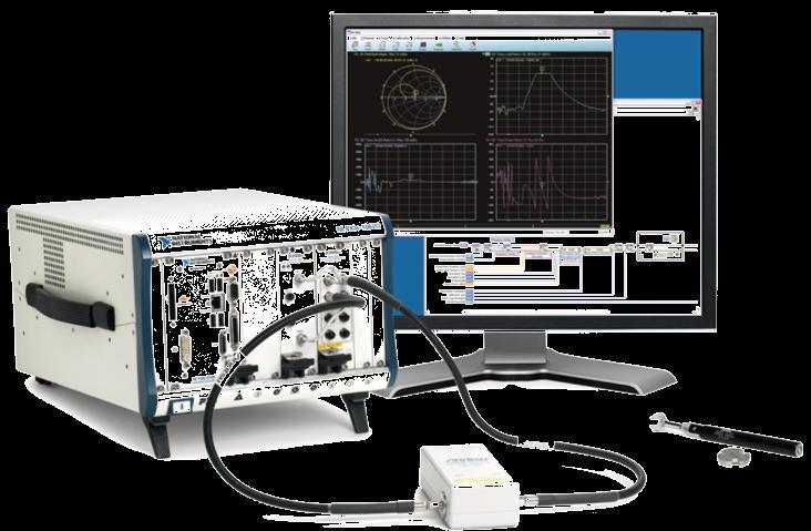
1 RF and Microwave Test and Design Roadshow 5 Locations across Australia and New Zealand ni.com
2 Design and test of RADAR systems

3 Agenda Radar Overview Tools Overview VSS LabVIEW PXI Design and Simulation Simulating the frond end Modeling signal processing Prototyping with real hardware
4 Overview of RADAR RADAR = radio detection and ranging Radar is an electromagnetic system for the detection and range of objects Where the reflection of the transmitted waveform is used for detection and range And its range (R) is determined by the equation out Rc Rc back R out back 2Rc Transmit Pulse R 2Rc Receive Pulse
5 Types of RADAR Signals CW (Continuous Wave) Detects velocity but not range FM CW Detects range through frequency difference of reflection Requires separate Tx and Rx Antennas Pulsed CW Detects range through round trip time of pulse Unambiguous range determined by pulse interval Pulse repetition frequency (PRF) PRF = 1 PRI Unambiguous Range c Ru = 2 PRF
6 Note on Unambiguous Range If PRF is 1000Hz then PRI = 1ms Maximum unambiguous range = 150km If we distribute the return signal over 200 bins us = 150km / 200 = 0.75km resolution A target 225km will have a delay of 1.5ms and will be mapped back to the 100 th range bin (0.5ms or 75km). Hence, this is called range ambiguity.


")


7 Designing a RADAR System Baseband (Digital) Pulse Generator Transmitter Analog (RF) Channel & Environmental LO Antenna Target Signal Processing Receiver AWR Visual System Simulator


8 RADAR Design and Test Ideal flow enables design tools to be leveraged by test group PXI and LabVIEW can be used in design-through-test Focus of Today s Discussion
9 Tools Overview

10 AWR s Visual System Simulator EDA Solution for System Design Mode s include: Time Domain Complex Envelope Spur Analysis RADAR library includes Full system simulation CFAR, MTI, and MDT Target and antenna modeling RF Link simulation includes Amplifier, Mixer, Filter Co-simulate with MWO circuits Co-simulate with hardware


11 National Instruments HW and SW NI LabVIEW Software Graphical programming environment Instrument control Signal processing algorithms Visualization and graphing NI PXI Hardware PC-based instruments RF signal generators and analysers Instrument Control Visualization & Display Signal Processing


12 Signal Processing in LabVIEW Modulation & Demodulation Signal Operation Signal Creation Filtering (FIR, IIR, etc.) Spectrogram
13 Connecting LabVIEW and VSS + Characterize simulated RF parts with LabVIEW measurements Prototype systems designs with physical hardware Control instruments from AWR s VSS environment

14 Importing LabVIEW Code in VSS VSS Environment LabVIEW Environment LabVIEW controls and indicators get mapped to input and output ports of a LabVIEW Node on the VSS diagram
15 RADAR Pulse Generation Pulse Generator Transmitter LO Antenna Target Signal Processing Receiver


16 Chirp Pulse Creation in LabVIEW Basic chirp signal can be created by FM modulating a ramp message signal.
17 RADAR Tx Chain Analysis Pulse Generator Transmitter LO Antenna Target Signal Processing Receiver
18 Transmit Chain Analysis Analysis methods in VSS include Link budget analysis Spur analysis Custom analysis possible in LabVIEW AMP_B Behavioral PA or NL_S TP M_PROBE PORTDIN BPFB AMP_B BPFB IN MIXER_B OUT BPFE AMP_B BPFE IN MIXER_B OUT BPFB AMP_B BPFB ISOLATOR PORTDOUT MHz LO LO 9015MHz TONE TONE MMIC PA 340MHz 8665MHz
19 Link budget Analysis Results: Cascaded NF = 4.65dB Available Gain = 59.5dB Power level at 9015MHz = 59.55dBm 5 4 DB(C_NF(TP.Start,TP.Stop,0,1,0,1))[1] RFB Tx System RFB C_NF for TX db p Gain RFB Cumulative Gain for TX DB(C_GA(TP.Start,TP.Stop,1,0,1))[1] RFB Tx System db p Noise Figure p1: Cascaded Noise Figure, Signal, Cumulative, db Freq=9015 MHz 0 p1: Available Gain, Cumulative, db Freq=9015 MHz 0-20 S4\BPFB (F1) S4\AMP_B (A1) S4\BPFB (F2) S4\MIXER_B (Mixer1) S4\BPFE (F3) S4\AMP_B (A2) S4\BPFE (F4) S4\MIXER_B (Mixer2) S4\BPFB (F5) S4\AMP_B (A5) S4\AMP_B (A4) S4\BPFB (F6) S4\ISOLATOR (S8) TX_ANTENNA (S7) S4\BPFB (F1) S4\AMP_B (A1) S4\BPFB (F2) S4\MIXER_B (Mixer1) S4\BPFE (F3) S4\AMP_B (A2) S4\BPFE (F4) S4\MIXER_B (Mixer2) S4\BPFB (F5) S4\AMP_B (A5) S4\AMP_B (A4) S4\BPFB (F6) S4\ISOLATOR (S8) TX_ANTENNA (S7)
20 Time Domain Analysis LabVIEW can be used for custom time domain analysis Complex signals using the measured phase (Θ) vs. time Linear pulse phase vs. time has constant change Θ(t) should have a U-shape dθ/dt should have a linear slope d 2 Θ/dt 2 should appear as a DC signal +

21 Basic Pulse Analysis in LabVIEW Input Waveform First derivative should appear as a ramp on a linear pulse Second derivative should appear DC on a perfectly linear pulse

22 Demo: Measuring Pulse Linearity Pulse is no longer linear due to group delay through a narrowband filter.


23 Generating Pulses with Hardware PXIe-5673 Vector Signal Generator Frequency: 100 MHz to 6.6 GHz Phase Noise: -110 dbc/hz (10 khz offset at 1 GHz) Bandwidth: up to 100 MHz QuickSyn Synthesizer Frequency: 200 MHz to 20 GHz Phase Noise: -138 dbc/hz (10 khz offset at 1 GHz) AM, FM, and Pulse modulation


24 Using a VSA to Analyze Pulses PXIe-5665 Frequency Range: 20 Hz to 14 GHz Phase Noise: -130 dbc/hz (10 khz offset at 1 GHz) Bandwidth: up to 50 MHz Phase Matrix VSA Frequency Range: 100 khz to 26.5 GHz Phase Noise: -118 dbc/hz (10 khz offset at 1 GHz) Bandwidth: up to 350 MHz
25 RADAR Antenna & Target Modeling Pulse Generator Transmitter LO Antenna Target Signal Processing Receiver


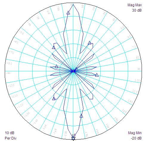
26 Antenna Characterization with a VNA PXIe Controller PXIe-5630 VNA PXI Motion Control Motor rotates antenna PXIe-5630 VNA Frequency: 10 MHz to 6GHz Measurements: S11 & S21 Dynamic Range: >100 db Typical Accuracy: < ± 0.1 db, 0.1 deg Sweep Speed: 400 us/pt
27 Antenna Modeling Parameters include Gain Effective Area Efficiency Directivity Polarization VSWR Free Space Impedance Z in and Z out respectively
28 Modeling the Target in VSS Delay and Doppler due to target velocity and distance Reflected Signal RCS EIRP Sets signal power received at target according to distance For statistical variation on RCS PWR
29 RADAR Rx Chain Analysis Pulse Generator Transmitter LO Antenna Target Signal Processing Receiver
30 Receive Chain Analysis Analysis metrics include Noise figure/sensitivity P1dB Group delay M_PROBE AMP_B OUT MIXER_B IN BPFE AMP_B BPFE OUT MIXER_B IN BPFB AMP_B BPFB ORTDOUT BPFB 10MHz LO 350MHz LO LNA PORTDIN 9015MHz TONE TONE 340MHz 8665MHz
31 Time (us) DB(C_HDRM(TP.Start,TP.End,1,0,1,1,1))[1,T] RFB RX System DB(C_HDRM(TP.Start,TP.End,1,0,1,1,1))[1,7] RFB RX System Receiver RF Analysis Noise RFB C_NF for RX 3.5 Figure 80 RFB Cascaded Headroom of RX link P1dB p2p1 p9p8 p7 p6 p5 p4 p db p1: Cascaded Noise Figure, Signal, Cumulative, db p2: Cascaded Noise Figure, Signal, Cumulative, db Freq=10 MHz Freq=10 MHz PWR=-70 PWR=-66 p3: Cascaded Noise Figure, Signal, Cumulative, db p4: Cascaded Noise Figure, Signal, Cumulative, db Freq=10 MHz Freq=10 MHz PWR=-62 PWR=-58 p5: Cascaded Noise Figure, Signal, Cumulative, db p6: Cascaded Noise Figure, Signal, Cumulative, db Freq=10 MHz Freq=10 MHz PWR=-54 PWR=-50 p7: Cascaded Noise Figure, Signal, Cumulative, db p8: Cascaded Noise Figure, Signal, Cumulative, db Freq=10 MHz Freq=10 MHz PWR=-46 PWR=-42 p9: Cascaded Noise Figure, Signal, Cumulative, db Freq=10 MHz PWR= p1: P1dB Headroom, Gain Adjusted, db Freq=10 MHz PWR=-46 p2: P1dB Headroom, Gain Adjusted, db Freq=10 MHz PWR=-70 p2 p db db 1-20 S1\BPFB (F6) S1\AMP_B (A4) S1\BPFB (F1) S1\MIXER_B (A1) S1\BPFE (F4) S1\AMP_B (A2) S1\BPFE (F2) S1\MIXER_B (A3) S1\AMP_B (A6) S1\BPFB (F3) S1\BPFB (F6) S1\AMP_B (A4) S1\BPFB (F1) S1\MIXER_B (A1) S1\BPFE (F4) S1\AMP_B (A2) S1\BPFE (F2) S1\MIXER_B (A3) S1\AMP_B (A6) S1\BPFB (F3) RFB C_GD RX p1: Absolute Group Delay, us PWR=-70 C_GD(TP.Start,TP.End,0,1,0,1,0)[X,T] (us) RFB RX System 1 p1 Group Delay RX IF Frequency (MHz)
32 RADAR Receiver Algorithms Pulse Generator Transmitter LO Antenna Target Signal Processing Receiver
33 Receiver Algorithms Basic Algorithms Range and velocity through correlation Advanced Algorithms Enable detections in difficult environments Examples include: Moving Target Indicator (MTI) Moving Target Detector (MTD) Constant False Alarm (CFAR)
 Chirp System Chirp,180,4,0,0,0,0,0,0) Chirp System Range Detection Through Correlation Chirp generator")
 Range from target 6Km TP From Tx Link 2 0.15 0.")
34 WVFM(S13\TP.Compressed.Chirp,180,4,0,0,0,0,0,0) Chirp System WVFM(S13\TP.Compressed.Chirp,180,4,0,0,0,0,0,0) Chirp System Range Detection Through Correlation Chirp generator PORTDIN SUBCKT DCOUPLER_ PORTDOUT 4 3 Output of Correlator 41.8 us Coupler 2 1 To Tx Link Time (us) Range from target 6Km TP From Tx Link Output of Correlator us CORRELATOR Correlator PORTDIN Time (us) Range from target 23Km

35 Input MDT Algorithm in LabVIEW

36 Example output of MTD Algorithm

37 Conclusion RADAR design requires combination of HW and Software RF front end design design and test Receiver algorithm prototyping National Instruments provides a complete solution for Visual System simulator for front end simulation LabVIEW for pulse creation and signal processing PXI instruments for physical RADAR test
Complete RF And Microwave Design Flow with AWR Design Environment. Tabish Khan, AWR Corporation
 Complete RF And Microwave Design Flow with AWR Design Environment Tabish Khan, AWR Corporation Traditional Serial Design Flow Separate tools, user interfaces, netlists and databases System Design Design
Simulating and Testing of Signal Processing Methods for Frequency Stepped Chirp Radar
 Test & Measurement Simulating and Testing of Signal Processing Methods for Frequency Stepped Chirp Radar Modern radar systems serve a broad range of commercial, civil, scientific and military applications.
Lecture Topics. Doppler CW Radar System, FM-CW Radar System, Moving Target Indication Radar System, and Pulsed Doppler Radar System
 Lecture Topics Doppler CW Radar System, FM-CW Radar System, Moving Target Indication Radar System, and Pulsed Doppler Radar System 1 Remember that: An EM wave is a function of both space and time e.g.
GET10B Radar Measurement Basics- Spectrum Analysis of Pulsed Signals. Copyright 2001 Agilent Technologies, Inc.
 GET10B Radar Measurement Basics- Spectrum Analysis of Pulsed Signals Copyright 2001 Agilent Technologies, Inc. Agenda: Power Measurements Module #1: Introduction Module #2: Power Measurements Module #3:
RF and Microwave Test and Design Roadshow 5 Locations across Australia and New Zealand
 RF and Microwave Test and Design Roadshow 5 Locations across Australia and New Zealand Advanced VNA Measurements Agenda Overview of the PXIe-5632 Architecture SW Experience Overview of VNA Calibration
Scalable Front-End Digital Signal Processing for a Phased Array Radar Demonstrator. International Radar Symposium 2012 Warsaw, 24 May 2012
 Scalable Front-End Digital Signal Processing for a Phased Array Radar Demonstrator F. Winterstein, G. Sessler, M. Montagna, M. Mendijur, G. Dauron, PM. Besso International Radar Symposium 2012 Warsaw,
Advances in RF and Microwave Measurement Technology
 1 Advances in RF and Microwave Measurement Technology Chi Xu Certified LabVIEW Architect Certified TestStand Architect New Demands in Modern RF and Microwave Test In semiconductor and wireless, technologies
Stephen Plumb National Instruments
 RF and Microwave Test and Design Roadshow Cape Town and Midrand October 2014 Stephen Plumb National Instruments Our Mission We equip engineers and scientists with tools that accelerate productivity, innovation,
Advances in RF and Microwave Measurement Technology
 1 Advances in RF and Microwave Measurement Technology Rejwan Ali Marketing Engineer NI Africa and Oceania New Demands in Modern RF and Microwave Test In semiconductor and wireless, technologies such as
Reconfigurable 6 GHz RF Vector Signal Transceiver with 1 GHz Bandwidth
 CALIBRATION PROCEDURE PXIe-5840 Reconfigurable 6 GHz RF Vector Signal Transceiver with 1 GHz Bandwidth This document contains the verification procedures for the PXIe-5840 vector signal transceiver. Refer
RF, HIL and Radar Test
 RF, HIL and Radar Test Abhay Samant Marketing Manager India, Russia and Arabia RF Hardware In The Loop Complex Radio Environment Components of RF HIL Communication Modems Channel Simulation GPS Simulation
Keysight Technologies
 Keysight Technologies Generating Signals Basic CW signal Block diagram Applications Analog Modulation Types of analog modulation Block diagram Applications Digital Modulation Overview of IQ modulation
Pulsed VNA Measurements:
 Pulsed VNA Measurements: The Need to Null! January 21, 2004 presented by: Loren Betts Copyright 2004 Agilent Technologies, Inc. Agenda Pulsed RF Devices Pulsed Signal Domains VNA Spectral Nulling Measurement
RF/IF Terminology and Specs
 RF/IF Terminology and Specs Contributors: Brad Brannon John Greichen Leo McHugh Eamon Nash Eberhard Brunner 1 Terminology LNA - Low-Noise Amplifier. A specialized amplifier to boost the very small received
S-Band 2.4GHz FMCW Radar
 S-Band 2.4GHz FMCW Radar Iulian Rosu, YO3DAC / VA3IUL, Filip Rosu, YO3JMK, http://qsl.net/va3iul A Radar detects the presence of objects and locates their position in space by transmitting electromagnetic
ELEC RADAR FRONT-END SUMMARY
 ELEC Radar Front-End is designed for FMCW (including CW) radar application. The output frequency of each RX provides range, speed, and amplitude information to DSP. It will detect target azimuth angle
SmartSpice RF Harmonic Balance Based RF Simulator. Advanced RF Circuit Simulation
 SmartSpice RF Harmonic Balance Based RF Simulator Advanced RF Circuit Simulation SmartSpice RF Overview Uses harmonic balance approach to solve system equations in frequency domain Well suited for RF and
Understanding RF and Microwave Analysis Basics
 Understanding RF and Microwave Analysis Basics Kimberly Cassacia Product Line Brand Manager Keysight Technologies Agenda µw Analysis Basics Page 2 RF Signal Analyzer Overview & Basic Settings Overview
PXIe Contents CALIBRATION PROCEDURE. Reconfigurable 6 GHz RF Vector Signal Transceiver with 200 MHz Bandwidth
 IBRATION PROCEDURE PXIe-5646 Reconfigurable 6 GHz Vector Signal Transceiver with 200 MHz Bandwidth This document contains the verification and adjustment procedures for the PXIe-5646 vector signal transceiver.
WIRELESS TRANSCEIVER ARCHITECTURE
 WIRELESS TRANSCEIVER ARCHITECTURE BRIDGING RF AND DIGITAL COMMUNICATIONS Pierre Baudin Wiley Contents Preface List of Abbreviations Nomenclature xiii xvii xxi Part I BETWEEN MAXWELL AND SHANNON 1 The Digital
Understanding New Pulse-analysis Techniques
 Understanding New Pulse-analysis Techniques Giuseppe Savoia Keysight Technologies Aerospace Defense Symposium Agenda Concept for Radar/Pulse signal analysis AD Symposium Page 2 Vector signal analyzers
Linking RF Design and Test Connecting RF Design Software to LabVIEW & Instruments
 Linking RF Design and Test Connecting RF Design Software to LabVIEW & Instruments Future of RF System Design RF/Microwave Circuit Design Electromagnetic Simulation Link Budget Analysis System simulation
RF and Microwave Test and Design Roadshow 5 Locations across Australia and New Zealand
 RF and Microwave Test and Design Roadshow 5 Locations across Australia and New Zealand Advanced PXI Technologies Signal Recording, FPGA s, and Synchronization Outline Introduction to the PXI Architecture
Increasing Automotive Safety with 77/79 GHz Radar Solutions for ADAS Applications
 Increasing Automotive Safety with 77/79 GHz Radar Solutions for ADAS Applications FTF-AUT-F0086 Patrick Morgan Director, Safety Systems Business Unit Ralf Reuter Manager, Radar Applications and Systems
SmartSpice RF Harmonic Balance Based and Shooting Method Based RF Simulation
 SmartSpice RF Harmonic Balance Based and Shooting Method Based RF Simulation Silvaco Overview SSRF Attributes Harmonic balance approach to solve system of equations in frequency domain Well suited for
Design, Optimization and Production of an Ultra-Wideband (UWB) Receiver
 Receiver") Application Note Design, Optimization and Production of an Ultra-Wideband (UWB) Receiver Overview This application note describes the design process for an ultra-wideband (UWB) receiver, including both
Application Note Design, Optimization and Production of an Ultra-Wideband (UWB) Receiver Overview This application note describes the design process for an ultra-wideband (UWB) receiver, including both
Advanced RF Measurements You Didn t Know Your Oscilloscope Could Make. Brad Frieden Philip Gresock
 Advanced RF Measurements You Didn t Know Your Oscilloscope Could Make Brad Frieden Philip Gresock Agenda RF measurement challenges Oscilloscope platform overview Typical RF characteristics Bandwidth vs.
Fundamentals Of Commercial Doppler Systems
 Fundamentals Of Commercial Doppler Systems Speed, Motion and Distance Measurements I. Introduction MDT manufactures a large variety of microwave oscillators, transceivers, and other components for the
Keysight Technologies Pulsed Antenna Measurements Using PNA Network Analyzers
 Keysight Technologies Pulsed Antenna Measurements Using PNA Network Analyzers White Paper Abstract This paper presents advances in the instrumentation techniques that can be used for the measurement and
NI AWR Design Environment Radar Design Solutions
 ni.com/awr ni.com/awr NI AWR Design Environment Radar Design Solutions NI AWR Design Environment - At a Glance Fully Integrated Design Platform Microwave Office - MMIC, RF PCB and module circuit design
Case Study: and Test Wireless Receivers
 Case Study: Using New Technologies to Design and Test Wireless Receivers Agenda Architecture of a receiver Basic GPS Receiver Measurements Case Study 1: GPS Simulation How Testing Works Simulation vs.
Bridging the Gap between System & Circuit Designers
 Bridging the Gap between System & Circuit Designers October 27, 2004 Presented by: Kal Kalbasi Q & A Marc Petersen Copyright 2003 Agilent Technologies, Inc. The Gap System Communication System Design System
Radio with COTS Technologies. ATE Systems Engineer
 Signal Intelligence and Software-Defined Radio with COTS Technologies Sacha Emery ATE Systems Engineer 1 Agenda Introduction Optimised signal processing with multicore and FPGAs Timing and synchronisation
Introducing the Keysight RF PXIe Vector Signal Analyzer & Generator M9391A & M9381A. Updated: August 2015
 Introducing the Keysight RF PXIe Vector Signal Analyzer & Generator M9391A & M9381A Updated: August 2015 Agenda Page 2 M9391A PXIe vector signal generator M9381A PXIe vector signal analyzer M9380A PXIe
RF Fundamentals Part 2 Spectral Analysis
 Spectral Analysis Dec 8, 2016 Kevin Nguyen Keysight Technologies Agenda Overview Theory of Operation Traditional Spectrum Analyzers Modern Signal Analyzers Specifications Features Wrap-up Page 2 Overview
AV3672 Series Vector Network Analyzer
 AV3672 Series Vector Network Analyzer AV3672A/B/C/D/E (10MHz 13.5 GHz/26.5 GHz/43.5 GHz/50 GHz/67 GHz) Product Overview: AV3672 series vector network analyzer include AV3672A (10MHz 13.5GHz), AV3672B (10MHz
CXE880 FIBRE OPTIC NODE
 Kari Mäki 4.3.2008 1(6) CXE880 FIBRE OPTIC NODE The CXE880 is a fibre deep optical node. It is designed for cases where high performance and cost effectiveness are a demand. Requirements of future networks,
Modern radio techniques
 Modern radio techniques for probing the ionosphere Receiver, radar, advanced ionospheric sounder, and related techniques Cesidio Bianchi INGV - Roma Italy Ionospheric properties related to radio waves
Understanding Low Phase Noise Signals. Presented by: Riadh Said Agilent Technologies, Inc.
 Understanding Low Phase Noise Signals Presented by: Riadh Said Agilent Technologies, Inc. Introduction Instabilities in the frequency or phase of a signal are caused by a number of different effects. Each
Designing Next-Generation AESA Radar Part 2: Individual Antenna Design
 Design Designing Next-Generation AESA Radar Part 2: Individual Antenna Design Figure 8: Antenna design Specsheet user interface showing the electrical requirements input (a), physical constraints input
PN9000 PULSED CARRIER MEASUREMENTS
 The specialist of Phase noise Measurements PN9000 PULSED CARRIER MEASUREMENTS Carrier frequency: 2.7 GHz - PRF: 5 khz Duty cycle: 1% Page 1 / 12 Introduction When measuring a pulse modulated signal the
DFS (Dynamic Frequency Selection) Introduction and Test Solution
 Introduction and Test Solution") DFS (Dynamic Frequency Selection) Introduction Sept. 2015 Present by Brian Chi Brian-tn_chi@keysight.com Keysight Technologies Agenda Introduction to DFS DFS Radar Profiles Definition DFS test procedure
DFS (Dynamic Frequency Selection) Introduction Sept. 2015 Present by Brian Chi Brian-tn_chi@keysight.com Keysight Technologies Agenda Introduction to DFS DFS Radar Profiles Definition DFS test procedure
ADI 2006 RF Seminar. Chapter II RF/IF Components and Specifications for Receivers
 ADI 2006 RF Seminar Chapter II RF/IF Components and Specifications for Receivers 1 RF/IF Components and Specifications for Receivers Fixed Gain and Variable Gain Amplifiers IQ Demodulators Analog-to-Digital
Addressing the Challenges of Wideband Radar Signal Generation and Analysis. Marco Vivarelli Digital Sales Specialist
 Addressing the Challenges of Wideband Radar Signal Generation and Analysis Marco Vivarelli Digital Sales Specialist Agenda Challenges of Wideband Signal Generation Challenges of Wideband Signal Analysis
Contents. CALIBRATION PROCEDURE NI PXIe GHz and 14 GHz RF Vector Signal Analyzer
 CALIBRATION PROCEDURE NI PXIe-5665 3.6 GHz and 14 GHz RF Vector Signal Analyzer This document contains the verification procedures for the National Instruments PXIe-5665 (NI 5665) RF vector signal analyzer
VHF Radar Target Detection in the Presence of Clutter *
 BULGARIAN ACADEMY OF SCIENCES CYBERNETICS AND INFORMATION TECHNOLOGIES Volume 6, No 1 Sofia 2006 VHF Radar Target Detection in the Presence of Clutter * Boriana Vassileva Institute for Parallel Processing,
Optical Delay Line Application Note
 1 Optical Delay Line Application Note 1.1 General Optical delay lines system (ODL), incorporates a high performance lasers such as DFBs, optical modulators for high operation frequencies, photodiodes,
APPENDIX B. 4. DEFINITIONS, SYMBOLS AND ABBREVIATIONS For the purposes of the present document, the following terms and definitions apply.
 APPENDIX B COMPLIANCE MEASUREMENT PROCEDURES FOR UNLICENSED-NATIONAL INFORMATION INFRASTRUCTURE DEVICES OPERATING IN THE 5.25-5.35 GHz AND 5.47-5.725 GHz BANDS INCORPORATING DYNAMIC FREQUENCY SELECTION
Modeling Physical PCB Effects 5&
 Abstract Getting logical designs to meet specifications is the first step in creating a manufacturable design. Getting the physical design to work is the next step. The physical effects of PCB materials,
DSA700 Series Spectrum Analyzer
 DSA700 Series Spectrum Analyzer Product Features: All-Digital IF Technology Frequency Range from 100 khz up to 1 GHz Min. -155 dbm Displayed Average Noise Level (Typ.) Min.
Lecture 3 SIGNAL PROCESSING
 Lecture 3 SIGNAL PROCESSING Pulse Width t Pulse Train Spectrum of Pulse Train Spacing between Spectral Lines =PRF -1/t 1/t -PRF/2 PRF/2 Maximum Doppler shift giving unambiguous results should be with in
Advances in RF and Microwave Measurement Technology
 1 Advances in RF and Microwave Measurement Technology Farris Alhorr Business Development Manager RF & Wireless Communication Farris.alhorr@ New Demands in Modern RF and Microwave Test In semiconductor
RF Board Design. EEC 134 Application Note. Jo Han Yu
 EEC 134 Application Note Jo Han Yu EEC 134 Application Note RF Board Design Introduction The objective of this application note is to outline the process of designing system and PCB layout for RF board
Multi Band Passive Forward Scatter Radar
 Multi Band Passive Forward Scatter Radar S. Hristov, A. De Luca, M. Gashinova, A. Stove, M. Cherniakov EESE, University of Birmingham Birmingham, B15 2TT, UK m.cherniakov@bham.ac.uk Outline Multi-Band
TETRA Tx Test Solution
 Product Introduction TETRA Tx Test Solution Signal Analyzer Reference Specifications ETSI EN 300 394-1 V3.3.1(2015-04) / Part1: Radio ETSI TS 100 392-2 V3.6.1(2013-05) / Part2: Air Interface May. 2016
New System Simulator Includes Spectral Domain Analysis
 New System Simulator Includes Spectral Domain Analysis By Dale D. Henkes, ACS Figure 1: The ACS Visual System Architect s System Schematic With advances in RF and wireless technology, it is often the case
Measuring Non-linear Amplifiers
 Measuring Non-linear Amplifiers Transceiver Components & Measuring Techniques MM3 Jan Hvolgaard Mikkelsen Radio Frequency Integrated Systems and Circuits Division Aalborg University 27 Agenda Non-linear
Principles of Modern Radar
 Principles of Modern Radar Vol. I: Basic Principles Mark A. Richards Georgia Institute of Technology James A. Scheer Georgia Institute of Technology William A. Holm Georgia Institute of Technology PUBLiSH]J
Behavioral Modeling of Nonlinear Amplifiers with Memory
 Behavioral Modeling of Nonlinear Amplifiers with Memory Michael Steer with Jie Hu and Aaron Walker Copyright 2009 to 2011 by M. Steer, J. Hu and A. Walker. Not to be posted on the web or distributed electronically
MAKING TRANSIENT ANTENNA MEASUREMENTS
 MAKING TRANSIENT ANTENNA MEASUREMENTS Roger Dygert, Steven R. Nichols MI Technologies, 1125 Satellite Boulevard, Suite 100 Suwanee, GA 30024-4629 ABSTRACT In addition to steady state performance, antennas
Agilent AN 1275 Automatic Frequency Settling Time Measurement Speeds Time-to-Market for RF Designs
 Agilent AN 1275 Automatic Frequency Settling Time Measurement Speeds Time-to-Market for RF Designs Application Note Fast, accurate synthesizer switching and settling are key performance requirements in
Agilent Antenna and RCS Measurement Configurations Using PNA Microwave Network Analyzers. White Paper
 Agilent Antenna and RCS Measurement Configurations Using PNA Microwave Network Analyzers White Paper Abstract As technology changes, new and different techniques for measuring and characterizing antenna
Faculty of Information Engineering & Technology. The Communications Department. Course: Advanced Communication Lab [COMM 1005] Lab 6.
![Faculty of Information Engineering & Technology. The Communications Department. Course: Advanced Communication Lab [COMM 1005] Lab 6.](/thumbs/90/102233011.jpg "Faculty of Information Engineering & Technology. The Communications Department. Course: Advanced Communication Lab [COMM 1005] Lab 6.") Faculty of Information Engineering & Technology The Communications Department Course: Advanced Communication Lab [COMM 1005] Lab 6.0 NI USRP 1 TABLE OF CONTENTS 2 Summary... 2 3 Background:... 3 Software
Faculty of Information Engineering & Technology The Communications Department Course: Advanced Communication Lab [COMM 1005] Lab 6.0 NI USRP 1 TABLE OF CONTENTS 2 Summary... 2 3 Background:... 3 Software
Advanced Test Equipment Rentals ATEC (2832)
") Established 1981 Advanced Test Equipment Rentals www.atecorp.com 800-404-ATEC (2832) R3000 EMI TEST RECEIVERS Fully IF digital EMI Receivers family for measurement of electromagnetic interference from
Established 1981 Advanced Test Equipment Rentals www.atecorp.com 800-404-ATEC (2832) R3000 EMI TEST RECEIVERS Fully IF digital EMI Receivers family for measurement of electromagnetic interference from
Model 7000 Series Phase Noise Test System
 Established 1981 Advanced Test Equipment Rentals www.atecorp.com 800-404-ATEC (2832) Model 7000 Series Phase Noise Test System Fully Integrated System Cross-Correlation Signal Analysis to 26.5 GHz Additive
Agilent 8360B/8360L Series Synthesized Swept Signal/CW Generators 10 MHz to 110 GHz
 Agilent 8360B/8360L Series Synthesized Swept Signal/CW Generators 10 MHz to 110 GHz ity. l i t a ers V. n isio c e r P. y t i l i ib Flex 2 Agilent 8360 Synthesized Swept Signal and CW Generator Family
Antenna and RCS Measurement Configurations Using Agilent s New PNA Network Analyzers
 Antenna and RCS Measurement Configurations Using Agilent s New PNA Network Analyzers John Swanstrom, Application Engineer, Agilent Technologies, Santa Rosa, CA Jim Puri, Applications Engineer, Agilent
Keysight Technologies Making Accurate Intermodulation Distortion Measurements with the PNA-X Network Analyzer, 10 MHz to 26.5 GHz
 Keysight Technologies Making Accurate Intermodulation Distortion Measurements with the PNA-X Network Analyzer, 10 MHz to 26.5 GHz Application Note Overview This application note describes accuracy considerations
Principles of Pulse-Doppler Radar p. 1 Types of Doppler Radar p. 1 Definitions p. 5 Doppler Shift p. 5 Translation to Zero Intermediate Frequency p.
 Preface p. xv Principles of Pulse-Doppler Radar p. 1 Types of Doppler Radar p. 1 Definitions p. 5 Doppler Shift p. 5 Translation to Zero Intermediate Frequency p. 6 Doppler Ambiguities and Blind Speeds
ER55 EMI TEST RECEIVER Family of automatic test receivers for measurement of electromagnetic interference from 9kHz to 1GHz
 ER55 EMI TEST RECEIVER Family of automatic test receivers for measurement of electromagnetic interference from 9kHz to 1GHz Compact designed and manufactured in compliance with CISPR 16-1, For Measurements
Frequency-Modulated Continuous-Wave Radar (FM-CW Radar)
") Frequency-Modulated Continuous-Wave Radar (FM-CW Radar) FM-CW radar (Frequency-Modulated Continuous Wave radar = FMCW radar) is a special type of radar sensor which radiates continuous transmission power
Frequency-Modulated Continuous-Wave Radar (FM-CW Radar) FM-CW radar (Frequency-Modulated Continuous Wave radar = FMCW radar) is a special type of radar sensor which radiates continuous transmission power
DIGITAL BEAM-FORMING ANTENNA OPTIMIZATION FOR REFLECTOR BASED SPACE DEBRIS RADAR SYSTEM
 DIGITAL BEAM-FORMING ANTENNA OPTIMIZATION FOR REFLECTOR BASED SPACE DEBRIS RADAR SYSTEM A. Patyuchenko, M. Younis, G. Krieger German Aerospace Center (DLR), Microwaves and Radar Institute, Muenchner Strasse
Reconfigurable 6 GHz Vector Signal Transceiver with I/Q Interface
 SPECIFICATIONS PXIe-5645 Reconfigurable 6 GHz Vector Signal Transceiver with I/Q Interface Contents Definitions...2 Conditions... 3 Frequency...4 Frequency Settling Time... 4 Internal Frequency Reference...
Ultra Wideband Indoor Radio Channel Measurements
 Ultra Wideband Indoor Radio Channel Measurements Matti Hämäläinen, Timo Pätsi, Veikko Hovinen Centre for Wireless Communications P.O.Box 4500 FIN-90014 University of Oulu, FINLAND email: matti.hamalainen@ee.oulu.fi
ELEN 701 RF & Microwave Systems Engineering. Lecture 4 October 11, 2006 Dr. Michael Thorburn Santa Clara University
 ELEN 7 RF & Microwave Systems Engineering Lecture 4 October, 26 Dr. Michael Thorburn Santa Clara University Lecture 5 Receiver System Analysis and Design, Part II Key Parameters Intermodulation Characteristics
Project Report. Laptop Based Radar
 Project Report Laptop Based Radar Selected Topics in Microelectronics I (EE 680) (Spring Semester 2013) Submitted by: 1. Mirmehdi seyedesfahlan 2. Mohammad hossein Nemati 3. Efe Ozturk 4. Haq Nawaz 5.
Application Note. StarMIMO. RX Diversity and MIMO OTA Test Range
 Application Note StarMIMO RX Diversity and MIMO OTA Test Range Contents Introduction P. 03 StarMIMO setup P. 04 1/ Multi-probe technology P. 05 Cluster vs Multiple Cluster setups Volume vs Number of probes
CXE880 FIBRE OPTIC NODE
 Kari Mäki 21.4.2011 1(6) CXE880 FIBRE OPTIC NODE The CXE880 is a fibre deep optical node. It is designed for cases where high performance and cost effectiveness are a demand. Requirements of future networks,
Texas A&M University Electrical Engineering Department ECEN 665. Laboratory #4: Analysis and Simulation of a CMOS Mixer
 Texas A&M University Electrical Engineering Department ECEN 665 Laboratory #4: Analysis and Simulation of a CMOS Mixer Objectives: To learn the use of periodic steady state (pss) simulation tools in spectre
RECOMMENDATION ITU-R SM Method for measurements of radio noise
 Rec. ITU-R SM.1753 1 RECOMMENDATION ITU-R SM.1753 Method for measurements of radio noise (Question ITU-R 1/45) (2006) Scope For radio noise measurements there is a need to have a uniform, frequency-independent
The Measurement and Characterisation of Ultra Wide-Band (UWB) Intentionally Radiated Signals
 Intentionally Radiated Signals") The Measurement and Characterisation of Ultra Wide-Band (UWB) Intentionally Radiated Signals Rafael Cepeda Toshiba Research Europe Ltd University of Bristol November 2007 Rafael.cepeda@toshiba-trel.com
The Measurement and Characterisation of Ultra Wide-Band (UWB) Intentionally Radiated Signals Rafael Cepeda Toshiba Research Europe Ltd University of Bristol November 2007 Rafael.cepeda@toshiba-trel.com
3250 Series Spectrum Analyzer
 The most important thing we build is trust ADVANCED ELECTRONIC SOLUTIONS AVIATION SERVICES COMMUNICATIONS AND CONNECTIVITY MISSION SYSTEMS 3250 Series Spectrum Analyzer > Agenda Introduction
Keysight Technologies PNA-X Series Microwave Network Analyzers
 Keysight Technologies PNA-X Series Microwave Network Analyzers Active-Device Characterization in Pulsed Operation Using the PNA-X Application Note Introduction Vector network analyzers (VNA) are the common
Frequently asked questions for 24 GHz industrial radar
 Frequently asked questions for 24 GHz industrial radar What is radar? Radar is an object-detection system that uses radio waves to determine the range, angle, or velocity of objects. A radar system consists
Building an Efficient, Low-Cost Test System for Bluetooth Devices
 Application Note 190 Building an Efficient, Low-Cost Test System for Bluetooth Devices Introduction Bluetooth is a low-cost, point-to-point wireless technology intended to eliminate the many cables used
Keysight Technologies Educational Overview of RF Power Measurement and Applications
 Keysight Technologies Educational Overview of RF Power Measurement and Applications Application Note Burst power signal Figure 13: RF Burst Power Measurement Duty cycle 02 Keysight Educational Overview
Model 845-M Low Noise Synthesizer
 Model 845-M Low Noise Synthesizer Features Low phase noise Fast switching down to 20 µs FM, Chirps, Pulse Internal OCXO, external variable reference Single DC supply Applications ATE LO for frequency converters
ELEN 701 RF & Microwave Systems Engineering. Lecture 2 September 27, 2006 Dr. Michael Thorburn Santa Clara University
 ELEN 701 RF & Microwave Systems Engineering Lecture 2 September 27, 2006 Dr. Michael Thorburn Santa Clara University Lecture 2 Radio Architecture and Design Considerations, Part I Architecture Superheterodyne
Model 855 RF / Microwave Signal Generator
 Features Very low phase noise Fast switching Phase coherent switching option 2 to 8 phase coherent outputs USB, LAN, GPIB interfaces Applications Radar simulation Quantum computing High volume automated
Keysight Technologies Gustaaf Sutorius
 1 1 mmw Seminar 2017 Keysight Technologies 18-04-2018 Gustaaf Sutorius Introduction & Agenda Why mmwave Industry needs & mmwave challenges Generating mmwave Analyzing mmwave Characterizing mmwave components
TSEK02: Radio Electronics Lecture 8: RX Nonlinearity Issues, Demodulation. Ted Johansson, EKS, ISY
 TSEK02: Radio Electronics Lecture 8: RX Nonlinearity Issues, Demodulation Ted Johansson, EKS, ISY RX Nonlinearity Issues: 2.2, 2.4 Demodulation: not in the book 2 RX nonlinearities System Nonlinearity
Pulsed S-Parameter Measurements using the ZVA network Analyzer
 Pulsed S-Parameter Measurements using the ZVA network Analyzer 1 Pulse Profile measurements ZVA Advanced Network Analyser 3 Motivation for Pulsed Measurements Typical Applications Avoid destruction of
Platform Migration 8510 to PNA. Graham Payne Application Engineer Agilent Technologies
 Platform Migration 8510 to PNA Graham Payne Application Engineer Agilent Technologies We set the standard... 8410 8510 When we introduced the 8510, we changed the way S-parameter measurements were made!
SIR-4011 MICROWAVE WIDEBAND DSP RECEIVER. WIDE FREQUENCY RANGE: GHz
 SIR-4011 MICROWAVE WIDEBAND DSP RECEIVER WIDE FREQUENCY RANGE: 0.5 18.0 GHz FEATURES Advanced Front Panel Graphics Display High Dynamic Range: In band Input IP3 > 0 dbm, NF< 15 db DSP Based AM, FM Video
DCNTS Phase Noise Analyzer 2 MHz to 1.8 / 26 / 50 / 140 GHz
 DCNTS Phase Noise Analyzer 2 MHz to 1.8 / 26 / 50 / 140 GHz Datasheet The DCNTS is the highest performance Phase Noise Analyzer with unique flexible capabilities as summarized below: Phase Noise Amplitude
NI PXIe-5601 Specifications
 NI PXIe-5601 Specifications RF Downconverter This document lists specifications for the NI PXIe-5601 RF downconverter (NI 5601). Use the NI 5601 with the NI PXIe-5622 IF digitizer and the NI PXI-5652 RF
APPH6040B / APPH20G-B Specification V2.0
 APPH6040B / APPH20G-B Specification V2.0 (July 2014, Serial XXX-XX33XXXXX-XXXX or higher) A fully integrated high-performance cross-correlation signal source analyzer for to 7 or 26 GHz 1 Introduction
PXIe Contents SPECIFICATIONS. 14 GHz and 26.5 GHz Vector Signal Analyzer
 SPECIFICATIONS PXIe-5668 14 GHz and 26.5 GHz Vector Signal Analyzer These specifications apply to the PXIe-5668 (14 GHz) Vector Signal Analyzer and the PXIe-5668 (26.5 GHz) Vector Signal Analyzer with
E-band and mmwave Components & Sub-Assemblies testing Challenges New Technology. VNA Roadshow Budapest 17/05/2016
 E-band and mmwave Components & Sub-Assemblies testing Challenges New Technology VNA Roadshow Budapest 17/05/2016 Agenda Applications drive the need Challenges faced by device characterization engineers
SETTING UP A WIRELESS LINK USING ME1000 RF TRAINER KIT
 SETTING UP A WIRELESS LINK USING ME1000 RF TRAINER KIT Introduction S Kumar Reddy Naru ME Signal Processing S. R. No - 05812 The aim of the project was to try and set up a point to point wireless link.