LTCC Components. ShenZhen Sunlord Electronics CO., LTD.
|
|
|
- Louise Murphy
- 5 years ago
- Views:
Transcription
1 LTCC Components
2 Content 1 The concept of LTCC About LTCC technology 2 Sunlord LTCC components Multilayer chip Antenna Multilayer chip Filter Multilayer chip Diplexer Multilayer chip Balun Multilayer chip Balance Filter Antenna Switch Module
3 What is LTCC? Low Temperature Co-fired Ceramics <900 on fire ceramic base Miniature circuit package technology Ceramic substrate Silver/Palladium conductor Multilayer circuit structure L/C/TL Component embedding

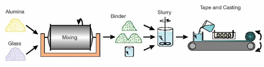
4 The flow chart of LTCC
5 Content 1 The concept of LTCC About LTCC technology 2 Sunlord LTCC components Multilayer chip Antenna Multilayer chip Filter Multilayer chip Diplexer Multilayer chip Balun Multilayer chip Balance Filter Antenna Switch Module


6 Bluetooth antenna types and characteristics Bluetooth antenna PCB antenna Features Printing directly on the PCB; no requirements on the height. Disadvantage Need some PCB space PIFA antenna Low profile, light weight, low back radiation. Narrow bandwidth, low gain, monotonous structure, not fit to mobile phones with flexible structure. Ceramic antenna Low profile, high-quality dielectric material, stable temperature coefficient Demand a certain clearance areas; need to tune matching circuit


7 Multilayer Chip Bluetooth antenna structure Outer electrode Coil pattern Ceramic

8 Antenna position in the circuit Antenna Filter Matching Circuit IC
9 Ordering Information SLDA 31-2R800G -S1 T F Type SLDA Multilayer Chip Antenna 2 External Dimensions (LxW) (mm) x1.6 3Center Frequency Example Nominal Value 2R800G MHz 2R470G MHz x x x x x2.0 4Series Code S1,01,etc. 5Packing 6Hazardous Substance Free Products F T Tape & Reel
10 Electrical Parameters Center frequency Bandwidth VSWR Return Loss Gain Efficiency
11 Terms and Descriptions Directivity We have seen that standard antennas emit more radiation in some directions than in others. Indeed, it is topologically impossible for an antenna to emit waves uniformly in all directions. We use directional pattern to identify the directivity. Center frequency There are many values of center frequency for Sunlord s chip Bluetooth antenna, such as 2.54GHz, 2.64GHz, 2.66GHz, 2.71GHz, etc. Range is ± 30MHz frequency. Greater frequency diversity will better meet customer needs.
12 Terms and Descriptions Bandwidth It is the frequency range to ensure electrical characteristic within the SPEC. VSWR VSWR (Voltage Standing Wave Ratio or, occasionally, Vertical Standing Wave Ratio), is a measure of how efficiently radio-frequency power is transmitted from a power source, through a transmission line, into a load (for example, from a power amplifier through a transmission line, to an antenna). It is calculated by the following formula. VSWR = (1+Γ)/(1-Γ) Γ (gamma) is the voltage reflection coefficient near the load. The value of VSWR is between 1 and infinity. If the load and transmission line are matched, Γ= 0, and VSWR = 1; If completely mismatched, VSWR is infinity.
13 Terms and Descriptions Return loss The Return Loss of a line is the ratio of the power reflected back from the line to the power transmitted to the line and measurement of return loss can reveal line faults due to mismatching. It is calculated by the following formula. Return Loss=20log( Γ ) Γ (gamma) is the voltage reflection coefficient near the load. For maximum power transfer the return power should be as small as possible. This means that when expressed in db, the return loss should be as large a negative number as possible. For example a return loss of -40dB is better than one of -20dB. Gain It stands for the ability of antenna to emit/receive signals to/from a particular direction. It can be measured by antenna s input and output power amplification. The higher the gain is, the further distance radio wave radiates. Efficiency Antenna efficiency is defined as the ratio of the total power radiated into space to the total power at the input port.
14 Typical antenna characteristic curve SLDA31-2R800G-S1TF
15 Property Range of Antennas Part No. Size (mm) Center Frequency (GHz) Bandwidth (MHz) Gain (dbi) SLDA SLDA SLDA SLDA SLDA SLDA SLDA SLDA SLDA SLDA SLDA ~
16 Application Chip antennas are mainly used for the 2.408GHz-2.480GHz frequency range of short-range wireless communication and other frequency range, such as RFID, CMMD, etc. For example - Cordless Phone - Wireless LAN Wireless Bluetooth Mouse Wireless Speaker - Bluetooth Headset Bluetooth phone - Wireless Bluetooth Car System - RFID - Mobile TV
17 Chip Antenna Selection - Based on the size of the antenna pad - Notice the physical environment of PCB - Larger size antenna will make better performance if the space is enough. - Choosing suitable frequency for antenna
18 Content 1 The concept of LTCC About LTCC technology 2 Sunlord LTCC components Multilayer chip Antenna Multilayer chip Filter Multilayer chip Diplexer Multilayer chip Balun Multilayer chip Balance Filter Antenna Switch Module
19 The classification of LC filter
20 Electrical Parameters Center frequency Insertion Loss Bandwidth Attenuation VSWR
21 Characteristic impedance : 50ohm Center frequency Bandwidth db S[i,j] Main Parameters of BPF Filter 0 p S21: Insertion Loss S21: Attenuation Return loss Ripple freq.(ghz) S11 S12 limit line
22 Terms and Descriptions Center Frequency(Fo) Usually defined as the midpoint frequency between 3dB frequency range of a band pass filter or stop filter. Insertion Loss (IL) Insertion loss is the loss of signal power resulting from the insertion of a device in a transmission line and is usually expressed in db. If the power transmitted to the load before insertion is PT and the power received by the load after insertion is PR, then the insertion loss in db is given by Attenuation It shows the signal loss of stop band.
23 Comparison of Filters Type Frequency Selective Insertion Loss Attenuation Volume Species Technology Temp. stability Cost SAW filter <2400 big better medium BP complex poor high LTCC filter >800 small good small BP, LP, HP, SP simple good low Dielectric Filter >800 medium good big BP medium good high


24 Sunlord s LC Filters 3.2* * * * * *0.5 bandpass bandpass lowpass bandpass bandpass highpass lowpass bandpass lowpass bandpass lowpass
25 Ordering Information SLF* 31-2R450G -E1 T F Type SLFL lowpass 2 External Dimensions (LxW)(mm) SLFB bandpass 31(1206) 3.2x1.6 SLFH highpass 21(0805) 2.0x1.2 18(1608) 1.6x0.8 3 Center Frequency 15(1005) 1.0x0.5 Example 0R847G 2R470G Nominal Value 847.5MHz MHz 5 Packing B T Bulk Package Tape & Reel 4 Series Code E1,G1,T1,etc. 6 Hazardous Substance Free Products F


")


26 Low-pass Filter Example Part Number Center Frequency Band width IL in BW max. ) IL in BW max. ~85 ) Attenuation Ripple in BW VSWR in BW Characteristic Impedance (Nom.) SLFL21-2R450G-G9TF MHz fo±50.0mhz 0.5 db 0.5 db 27.0dB min. at 2xF0 MHz 25.0dB min. at 3xF0 MHz 25.0dB min. at 4xF0 MHz 0.25 db max 1.80 max. 50 ohm db(s(1,1)) db(s(2,1)) Frequency(GHz)
 2.2 db IL in BW max. (@-40 ~85 ) 2.5 db Attenuation Ripple in BW VSWR in BW 24dB min.")
) db(s(2,1)) 0-10 -20-30 -40 Characteristic Impedance (Nom.")
27 Band-pass Filter Example Part Number SLFB18-2R450G-02TF Center Frequency MHz Band width fo±50.0mhz IL in BW max. ) 2.2 db IL in BW max. ~85 ) 2.5 db Attenuation Ripple in BW VSWR in BW 24dB min. at 880~960MHz 20dB min. at 1710~1990MHz 15.5dB min. at 4800~5000MHz 19.5dB min. at 7200~7500MHz 1.5 db max 2.1 max. db(s(1,1)) db(s(2,1)) Characteristic Impedance (Nom.) 50 ohm Frequency(GHz)


")


28 High-pass Filter Example Part Number Center Frequency Band width IL in BW max. ) IL in BW max. ~85 ) Attenuation Ripple in BW VSWR in BW Characteristic Impedance (Nom.) SLFH21-1R925G-01TF MHz fo±275.0mhz 2.2 db 2.2 db 25.0dB Min. at 900~1450 MHz 1.6dB max. at 1650~2200MHz 0.39dB max. at 1650~1675MHz 1.0dB max. at 1625~1650MHz 2.1 max. 50 ohm db(s(1,1)) db(s(2,1)) Frequency(GHz)
29 Content 1 The concept of LTCC About LTCC technology 2 Sunlord LTCC components Multilayer chip Antenna Multilayer chip Filter Multilayer chip Diplexer Multilayer chip Balun Multilayer chip Balance Filter Antenna Switch Module


30 About Diplexer In modern communication systems, multi transmission system share a single antenna. The diplexer is used as to isolate two frequency ranges, such as transmitting and receiving signals, or two different bands. It is a key component in RF front-end and its performance will directly affect the quality of the whole system of communication.
31 Electrical Parameters Center Frequency Bandwidth Insertion Loss Isolation VSWR
32 Terms and Descriptions Center Frequency and Bandwidth Diplexer has two separate working frequency range and at each working frequency range, the insertion loss should be low enough and the attenuation at the other frequency range should be high. Isolation The attenuation at another frequency range when one frequency range working normally.
33 Ordering Information SLFD 21-2R450G -01 T Type SLFD Diplexer 2External Dimensions (LxW)(mm) 32(1210) 3.2x2.5 21(0805) 2.0x1.2 3Center Frequency Example Nominal Value 4Series Code 01,02 2R200G 2R450G MHz MHz 5Packing Tape & Reel
34 Diplexer characteristic curve SLFD32-2R200G-01T db(s(1,1)) db(s(3,1)) db(s(2,1)) db(s(2,3)) db(s(3,3)) db(s(2,2)) freq, GHz freq, GHz
35 Content 1 The concept of LTCC About LTCC technology 2 Sunlord LTCC components Multilayer chip Antenna Multilayer chip Filter Multilayer chip Diplexer Multilayer chip Balun Multilayer chip Balance Filter Antenna Switch Module
36 About Balun Function: Impedance matching Signal balance Single-End Circuit Antenna LNA Balun Unbalanced To balanced Differential Circuit IC Push-Pull Pull Amp
37 Impedance matching By adding a component or circuit to balance input impedance and output impedance to achieve the maximum output. 50Ω R ± jx Single-ended ended differential transfer Non-balanced signal is converted to balanced signals. The input signal is converted into two signals with the same amplitude and the opposite phase close to 180 degrees. T T/2 T/2
38 Ordering Information SLBL 18-0R960G T Type SLBL Balun 3Center Frequency 2External Dimensions (LxW)(mm) 18(0603) 1.6x0.8 21(0805) 2.0x1.2 Example 0R960G Nominal Value 960.0MHz 5Packing 4Balance impedance 05 50Ω Ω Tape & Reel
39 Balun characteristic curve SLBL21-2R400G-10-01T 0-10 Sss11 Sdd freq, GHz
40 Content 1 The concept of LTCC About LTCC technology 2 Sunlord LTCC components Multilayer chip Antenna Multilayer chip Filter Multilayer chip Diplexer Multilayer chip Balun Multilayer chip Balance Filter Antenna Switch Module
41 About Balance Filter RF front-end module Single-End Circuit LNA Balance-Filter Differential Circuit Matchin g circuit RX Diplexer TX BP F Balun I C Coupler PA LPF BALUN
42 Balun + Application BPF = Balance Filter Between the antenna and the IC for balanced and unbalanced conversion, the function of the filtering. Antenna LNA Balun-Filter IC MTK:6612\ CSR:BC4\BC5 BC5\BC6\B C7
43 Ordering Information SLFBF 21 2R450G A02 T F SLFBF Type Balanced Filter 2 External Dimensions (L W) (mm) Center Frequency 4 Series Code 2R450G MHz A02 5 Packing 6 Packing T Tape Carrier Package F
44 Product Example Part Number Unbalance Port Impedance Balance Port Impedance Frequency Range (BW) Insertion Loss in BW Attenuation (Absolute value) Phase Difference Amplitude difference Unbalance Port V.S.W.R in BW Balance Port V.S.W.R in BW Power Capacity SLFBF-212R450G 212R450G-A02TF 50 ohm Conjugate match to MTK MT6612/ ±50.0 MHz 2.8dB max. at db max. at -40 to db min at ~960.00MHz 30.0 db min at ~ MHz 16.0 db min at ~ MHz 17.0 db min at ~ MHz 180 ± ±10 1.5dB max 2.10 max 2.10 max 500 mw max.
45 Electrical Characteristics Frequency Sss11 Sdd22 Sds freq, GHz
46 Electrical Characteristics Phase Difference and Amplitude difference Amp_Diff Pha_Diff freq, GHz
47 Content 1 The concept of LTCC About LTCC technology 2 Sunlord LTCC components Multilayer chip Antenna Multilayer chip Filter Multilayer chip Diplexer Multilayer chip Balun Multilayer chip Balance Filter Antenna Switch Module


48 About ASM Antenna Switch Module for RF front end can switch different frequency bands and different modes by frequency and time division. There are several types technology to achieve this function, such as PIN diode GaAs phemt and Ultra CMOS.
49 Comparison of Different ASMs Types IL Harmonics ESD Cost Size PIN Diode GaAs CMOS bad medium good


50 Sunlord s LTCC ASM Sunlord applies LTCC technology to embed main circuit function and surface mount discrete components which can not be embedded, such as pin diode, chip resistor and chip inductor. LTCC ASM has good performance in harmonics, ESD protection and cost. Dual band Triple band
51 Ordering Information SLASM 33 T1 CL1 T SLASM Type Antenna Switch Module 2 External Dimensions (L W) (mm) 33 [1212] Internal Code 4 Material Code V4 Dual band CL1 T1 Triple band 5 T Packing Tape Carrier Package
52 Electrical Characteristics GSM850/900 Band and GSM1800/1900 Band RX_Mode SLASM33V4CL1T
53 Electrical Characteristics GSM850/900-Tx_Mode SLASM33V4CL1T
54 Electrical Characteristics GSM1800/1900-Tx_Mode SLASM33V4CL1T
55 THANK YOU!
Discover TDK Solutions
 Discover TDK Solutions RF Components for Wireless Applications TDK RF Components & Services : Band Pass Filters Diplexers Low Pass Filters Couplers High Inductors Circulators/ Isolators Baluns Antennas
Top View (Near-side) Side View Bottom View (Far-side) .89±.08. 4x.280. Orientation Marker Orientation Marker.
 Side View Bottom View (Far-side) .89±.08. 4x.280. Orientation Marker Orientation Marker.") Model B2F2AHF Ultra Low Profile 168 Balun Ω to 2Ω Balanced Description The B2F2AHF is a low profile sub-miniature balanced to unbalanced transformer designed for differential input locations on data conversion
Model B2F2AHF Ultra Low Profile 168 Balun Ω to 2Ω Balanced Description The B2F2AHF is a low profile sub-miniature balanced to unbalanced transformer designed for differential input locations on data conversion
Top View (Near-side) Side View Bottom View (Far-side) ± ±.08. 4x.28. Orientation Marker Balanced port 1.
 Side View Bottom View (Far-side) ± ±.08. 4x.28. Orientation Marker Balanced port 1.") Model BD2FAHF Ultra Low Profile 168 Balun Ω to Ω Balanced Description The BD2FAHF is a low profile sub-miniature balanced to unbalanced transformer designed for differential input locations on data conversion
Model BD2FAHF Ultra Low Profile 168 Balun Ω to Ω Balanced Description The BD2FAHF is a low profile sub-miniature balanced to unbalanced transformer designed for differential input locations on data conversion
Model BD1631J50100AHF
 Model BD1631J51AHF Ultra Low Profile 85 Balun 5Ω to 1Ω Balanced Description The BD1631J51AHF is a low profile sub-miniature balanced to unbalanced transformer designed for differential inputs and output
Model BD3238N5050AHF. Ultra Low Profile 0404 Balun
 Model BD338N55AHF Ultra Low Profile 44 Balun 5Ω to 5Ω Balanced Description The BD338N55AHF is a low cost, low profile sub-miniature unbalanced to balanced transformer designed for differential inputs and
Return loss (db) Insertion loss (db) .56±.06 TBD. GND / DC Feed 1 + RF GND 2. Unbalanced Port Balanced Port Balanced Port.
 Insertion loss (db) .56±.06 TBD. GND / DC Feed 1 + RF GND 2. Unbalanced Port Balanced Port Balanced Port.") Model BD6N5AHF Ultra Low Profile 44 Balun 5Ω to Ω Balanced Description The BD6N5AHF is a low cost, low profile sub-miniature unbalanced to balanced transformer designed for differential inputs and output
Model BD6N5AHF Ultra Low Profile 44 Balun 5Ω to Ω Balanced Description The BD6N5AHF is a low cost, low profile sub-miniature unbalanced to balanced transformer designed for differential inputs and output
TDK RF Products Training Module for Mouser
 TDK RF Products Training Module for Mouser Jan, 2011 TDK RF Overview Introduction to TDK RF Components and their applications RF Product Marketing A ttenuation A ttenuation A ttenuation What is a BPF/LPF/Diplexer/Coupler/?
Model BD2425N50200AHF. Ultra Low Profile 0404 Balun 50Ω to 200Ω Balanced
 Model BD45N5AHF Ultra Low Profile 44 Balun 5Ω to Ω Balanced Description The BD45N5AHF is a low cost, low profile sub-miniature unbalanced to balanced transformer designed for differential inputs and output
Model BD1722J50100A00
 Ultra Low Profile 85 Balun 5Ω to 1Ω Balanced Description The BD1722J51A is a low profile sub-miniature balanced to unbalanced transformer designed for differential inputs and output locations on next generation
Model B0922N7575AHF Rev B. Ultra Low Profile 0404 Balun
 Model B9N7575AHF Ultra Low Profile 44 Balun 75Ω to 75Ω Balanced Description The B9N7575AHF is a low profile, low impedance mm square subminiature wideband unbalanced to balanced transformer designed for
Products. Dielectric Resonators. Description: Specifications: Attenuation:
 Dielectric Resonators Products Description: K&L s Dielectric Resonator Bandpass Filters are available in standard packages with a basic Chebychev design. Connectors available are SMA and RF pins. Through
Detailed Electrical Specifications: Specifications subject to change without notice. Broadband Narrowband 25 C
 fee Ultra Low Profile 85 Balun 75Ω to 75Ω Balanced Description The B225J7575AHF is a low profile sub-miniature balanced to unbalanced transformer designed for differential inputs and output locations on
CMT2300AW Schematic and PCB Layout Design Guideline
 AN141 CMT2300AW Schematic and PCB Layout Design Guideline Introduction This document is the CMT2300AW Application Development Guideline. It will explain how to design and use the CMT2300AW schematic and
Multilayer chip antenna application guide
 1. introduction Shenzhen Sunlord electronics Co. LTD Multilayer chip antenna application guide The chip antenna series is designed for the applications of ISM band 2.4GHz and CMMB, just like as Bluetooth
Model C0810J5003AHF. Ultra Low Profile db, 90 Hybrid Coupler
 Model C81J53AHF Ultra Low Profile 85 3 db, 9 Hybrid Coupler Description The C81J53AHF is a low cost, low profile sub-miniature high performance 3 db coupler in an easy to use surface mount package. It
Model BD4859L50100A00 Rev A
 Model BD4859L51A Ultra Small Low Profile 63 Balun 5Ω to 1Ω Balanced Description The BD4859L51A is an ultra-small low profile balanced to unbalanced transformer designed for differential inputs and output
CMOS 2.4GHZ ZIGBEE/ISM TRANSMIT/RECEIVE RFeIC
 CMOS 2.4GHZ ZIGBEE/ISM TRANSMIT/RECEIVE RFeIC Description 17 1 2 3 4 TXRX VDD VDD D 16 15 14 13 12 11 10 ANT 9 The is a fully integrated, single-chip, single-die RFeIC (RF Front-end Integrated Circuit)
INDEX ORDERING CODE...1~4 CHIP ANTENNA...5~11 HIGH FREQUENCY MULTILAYER BAND PASS FILTER...12~18 HIGH FREQUENCY MULTILAYER BALANCED FILTER...
 Table of Contents www.passivecomponent.com INDEX Subject Page ORDERING CODE...1~4 CHIP ANTENNA...5~11 HIGH FREQUENCY MULTILAYER BAND PASS FILTER...12~18 HIGH FREQUENCY MULTILAYER BALANCED FILTER...19~23
Model PD3150J5050S2HF
 Model PD315J55S2HF Ultra Low Profile 85 Power Divider 5Ω to 5Ω Description The PD315J55S2HF is a low profile, sub-miniature Wilkinson power divider in an easy to use surface mount package. The PD315J55S2HF
Model PD0409J7575S2HF
 Model PD49J77SHF Ultra Low Profile 8 Power Divider 7Ω to 7Ω Description The PD49J77SHF is a low profile, sub-miniature Wilkinson power divider in an easy to use surface mount package. The PD49J77SHF is
HIGH FREQUENCY PRODUCTS
 HIGH FREQUENCY PRODUCTS GPS patch antenna and active module GPS patch antenna (CP) 12x12x2 * (dbic/max.) 4-1.5 Polarization Axial ratio Temp. () CAN4313422021581B 12x12x4 9-1 CAN4313422031581B 13x13x4
Model PD0409J5050S2HF
 Model PD49JSHF Ultra Low Profile 8 Power Divider Ω to Ω Description The PD49JSHF is a low profile, sub-miniature Wilkinson power divider in an easy to use surface mount package. The PD49JSHF is ideal for
RADIO RECEIVERS ECE 3103 WIRELESS COMMUNICATION SYSTEMS
 RADIO RECEIVERS ECE 3103 WIRELESS COMMUNICATION SYSTEMS FUNCTIONS OF A RADIO RECEIVER The main functions of a radio receiver are: 1. To intercept the RF signal by using the receiver antenna 2. Select the
Model 2425B50-50C Rev. A
 rit Model 2425B50-50C Xinger Balun 50Ω to 100Ω Balanced Description The 2425B50-50C is a low profile sub-miniature balanced to unbalanced transformer designed for differential inputs and output locations
ACX Advanced Ceramic X
 FB2012 Series Multilayer Chip Band Pass Filter + Balun Features Monolithic SMD with small, low-profile and light-weight type. Applications 0.8 ~ 6 GHz wireless communication systems, including DECT/PACS/PHS/GSM/DCS
CMOS 2.4GHZ ZIGBEE/ISM TRANSMIT/RECEIVE RFeIC
 hot RFX2401C CMOS 2.4GHZ ZIGBEE/ISM TRANSMIT/RECEIVE RFeIC Description 1 2 3 4 TXRX 17 VDD VDD DNC 16 15 14 13 12 11 10 ANT 9 The RFX2401C is a fully integrated, single-chip, single-die RFeIC (RF Front-end
Johanson Technology, Inc. 2450BM14A0002 Matched Balun for the Nordic nrf24l01/nrf24l01+ Chipsets. November 2009
 Johanson Technology, Inc. 2450BM14A0002 Matched Balun for the Nordic nrf24l01/nrf24l01+ Chipsets November 2009 1. Introduction The nrf24l01/nrf24l01+ from Nordic Semiconductor is a 2.45GHz one chip, ultra
CMOS 2.4GHZ ZIGBEE/ISM TRANSMIT/RECEIVE RFeIC
 CMOS 2.4GHZ ZIGBEE/ISM TRANSMIT/RECEIVE RFeIC Description 17 1 2 3 4 TXRX VDD VDD D 16 15 14 13 12 11 10 ANT 9 The RFX2401C is a fully integrated, single-chip, single-die RFeIC (RF Front-end Integrated
SAW Bandpass Filter F2G12
 SAW Bandpass Filter FG Features WCDMA applications Usable bandwidth of 60 MHz No impedance matching require for operation at 50 Ω Ceramic Surface Mounted Device Package (.0 mm *.0 mm ) Singleended Operation
Model PD2328J5050S2HF
 Model PD2328J55S2HF Ultra Low Profile 85 Power Divider 5Ω to 5Ω Description The PD2328J55S2HF is a low profile, sub-miniature Wilkinson power divider in an easy to use surface mount package. The PD2328J55S2HF
Model C1517J5003AHF. Ultra Low Profile db, 90 Hybrid Coupler
 Model C57J53AHF Ultra Low Profile 85 3 db, 9 Hybrid Coupler Description The C57J53AHF is a low cost, low profile sub-miniature high performance 3 db coupler in an easy to use surface mount package. The
SAW Bandpass Filter F4521
 Features RF bandpass filter for CDMA0 CBand Tx. Part Usable bandwidth MHz (0 MHz ~ MHz) High attenuation No matching 0Ω singleended operation Ceramic Surface Mounted Device Package (.8 mm.8 mm ) RoHS compliant
CMOS 5GHz WLAN ac RFeIC WITH PA, LNA AND SPDT
 CMOS 5GHz WLAN 802.11ac RFeIC WITH PA, LNA AND SPDT RX LEN 16 RXEN ANT 15 14 13 12 11 Description RFX8051B is a highly integrated, single-chip, single-die RFeIC (RF Front-end Integrated Circuit) which
CMOS 2.4GHZ TRANSMIT/RECEIVE WLAN RFeIC
 CMOS 2.4GHZ TRANSMIT/RECEIVE WLAN RFeIC 17 1 RX 2 3 VDD VDD DNC 16 15 14 13 12 11 10 ANT Description The RFX2402C is a fully integrated, single-chip, single-die RFeIC (RF Front-end Integrated Circuit)
Model C2327J5003AHF Rev D
 Model C2327J53AHF Ultra Low Profile 85 3 db, 9 Hybrid Coupler Description The C2327J53AHF is a low cost, low profile sub-miniature high performance 3 db coupler in an easy to use surface mount package.
MCP to 2.5 GHz RF Front End IC. Description
 Description The contains a power amplifier (PA), a low noise amplifier (LNA), and two SPDT switch. It is a 0-pins IC by 4 4mm -QFN package. RF input and output impedance of are 50Ω matched. Therefore,
TQM679002A Data Sheet
 Block Diagram Rxp Rxn PABC PAEN Tx in Pdetect BTH Balun Product Description PA Directional Detector BTSW RXSW TXSW ANT The TQM679002A is full WLAN/BT front-end module in an ultra small 3mm x 3mm footprint
Low Cost Mixer for the 10.7 to 12.8 GHz Direct Broadcast Satellite Market
 Low Cost Mixer for the.7 to 12.8 GHz Direct Broadcast Satellite Market Application Note 1136 Introduction The wide bandwidth requirement in DBS satellite applications places a big performance demand on
Session 3. CMOS RF IC Design Principles
 Session 3 CMOS RF IC Design Principles Session Delivered by: D. Varun 1 Session Topics Standards RF wireless communications Multi standard RF transceivers RF front end architectures Frequency down conversion
ponents Com ped Lum Lumped Components
 Lumped Components Lumped Components K&L Microwave offers Lumped Component filters with a broad selection of frequencies, topologies, and mechanical configurations. Use of standard packages has enabled
Anaren 0805 (B0809J50ATI) balun optimized for Texas Instruments CC1100/CC1101 Transceiver
 balun optimized for Texas Instruments CC1100/CC1101 Transceiver") (ANN-2005) Rev B Page 1 of 13 Anaren 0805 (B0809J50ATI) balun optimized for Texas Instruments CC1100/CC1101 Transceiver Trong N Duong RF Co-Op Nithya R Subramanian RF Engineer Introduction The tradeoff
(ANN-2005) Rev B Page 1 of 13 Anaren 0805 (B0809J50ATI) balun optimized for Texas Instruments CC1100/CC1101 Transceiver Trong N Duong RF Co-Op Nithya R Subramanian RF Engineer Introduction The tradeoff
High Frequency Ceramic Solutions
 Page 1 of 6 Do you need a small sub-ghz or 2.4GHz antenna? Go to: /antennas General Specifications Part Number 9PC15A36 Frequency (MHz) 862-928 24-25 Insertion Loss (db) 1.8 typ (2. max.) 1.3 typ (1.6
Digital Step Attenuators offer Precision and Linearity
 Digital Step Attenuators offer Precision and Linearity (AN-70-004) DAT Attenuator (Surface Mount) Connectorized DAT attenuator (ZX76 Series) Connectorized DAT attenuator ZX76-31R5-PN attenuator with parallel
2.4 GHz ISM Band Working Frequency
 RFBLN 2012 (0805) Series RoHS Compliance MULTILAYER CERAMIC BALUN TRANSFORMER Halogens Free Product 2.4 GHz ISM Band Working Frequency P/N: RFBLN2012090A1T *Contents in this sheet are subject to change
CMOS 5GHz WLAN ac RFeIC WITH PA, LNA AND SPDT
 CMOS 5GHz WLAN 802.11ac RFeIC WITH PA, LNA AND SPDT RX LEN 16 RXEN ANT 15 14 13 12 11 Description RFX8051 is a highly integrated, single-chip, single-die RFeIC (RF Front-end Integrated Circuit) which incorporates
SMT Hybrid Couplers, RF Parameters and Applications
 SMT Hybrid Couplers, RF Parameters and Applications A 90 degree hybrid coupler is a four-port device used to equally split an input signal into two signals with a 90 degree phase shift between them. The
Part Numbering System
 Reactel Filters can satisfy a variety of filter requirements. These versatile units cover the broad frequency range of 2 khz to 5 GHz, and are available in either tubular or rectangular packages, connectorized
400 MHz 4000 MHz Low Noise Amplifier ADL5521
 FEATURES Operation from 400 MHz to 4000 MHz Noise figure of 0.8 db at 900 MHz Including external input match Gain of 20.0 db at 900 MHz OIP3 of 37.7 dbm at 900 MHz P1dB of 22.0 dbm at 900 MHz Integrated
2.4 GHz TX / RX Booster With Diversity Switch for IoT / BLE / ZigBee
 2.4 GHz TX / RX Booster With Diversity Switch for IoT / BLE / ZigBee NC DNC NC TXRX 21 1 2 3 4 5 VDD VDD 20 19 18 DNC DNC 17 16 6 7 8 9 TXEN RXEN PDET Mode 10 SWant 15 IND 14 ANTA 13 12 ANTB 11 DESCRIPTION
Synthesis of Optimal On-Chip Baluns
 Synthesis of Optimal On-Chip Baluns Sharad Kapur, David E. Long and Robert C. Frye Integrand Software, Inc. Berkeley Heights, New Jersey Yu-Chia Chen, Ming-Hsiang Cho, Huai-Wen Chang, Jun-Hong Ou and Bigchoug
Differential Input / Output Impedance Match SM X 5 mm Nominal Footprint Lid Symbolization (YY=year, WW=week, S=shift) 15 pf
 15 pf") SF1189B-1 Designed for WLAN IF Applications Low Insertion Loss 5.0 x 5.0 x 1.7 mm Suface-Mount Case Single Ended or Differential Input and Output Differential Output Complies with Directive 2002/95/EC
SF1189B-1 Designed for WLAN IF Applications Low Insertion Loss 5.0 x 5.0 x 1.7 mm Suface-Mount Case Single Ended or Differential Input and Output Differential Output Complies with Directive 2002/95/EC
DATASHEET. It needs tuning process for customer s device. AMOTECH
 Document Datasheet Type Dielectric Chip Antenna Application 1575.42 & 1592~1610MHz Part No. AMAN1003015ST03 Revision 1.0 DATASHEET Application GPS(1575.42 MHz) & Glonass (1592~1610 MHz) Features PIFA Structure
Chapter 2. The Fundamentals of Electronics: A Review
 Chapter 2 The Fundamentals of Electronics: A Review Topics Covered 2-1: Gain, Attenuation, and Decibels 2-2: Tuned Circuits 2-3: Filters 2-4: Fourier Theory 2-1: Gain, Attenuation, and Decibels Most circuits
Cavity Filters. Waveguide Filters
 Cavity Cavity Filters K&L Microwave s series of cavity filters covers the frequency range from 30 MHz to 40 GHz. These filters are available with 2 to 17 resonant sections and bandwidths from 0.2% to 50%.
Master Thesis. Mobile Phone Antenna Modelling. Umut Bulus. Supervised by Prof. Dr.-Ing. K. Solbach
 Master Thesis Mobile Phone Antenna Modelling Umut Bulus Supervised by Prof. Dr.-Ing. K. Solbach 2.3.28 Contents Introduction Theoretical Background Antenna Measurements on Different PCB Variations Investigation
PAR4CR: THE DEVELOPMENT OF A NEW SDR-BASED PLATFORM TOWARDS COGNITIVE RADIO
 PAR4CR: THE DEVELOPMENT OF A NEW SDR-BASED PLATFORM TOWARDS COGNITIVE RADIO Olga Zlydareva Co-authors: Martha Suarez Rob Mestrom Fabian Riviere Outline 1 Introduction System Requirements Methodology System
RFID Chip Antenna ACAJ-110- ACAJ-110-T Moisture Sensitivity Level (MSL) MSL = 1. SPECIFICATION Frequency Range. 868/915MHz VSWR
 MSL = 1. SPECIFICATION Frequency Range. 868/915MHz VSWR") Moisture Sensitivity Level (MSL) MSL = 1 FEATURES: Passive Dielectric Chip Antenna Covering dual ISM bands 868MHz and 915MHz SMA mount, Reflowable to 255 degrees C max. Compact Dimensions (9.0mm x 3.0mm
Moisture Sensitivity Level (MSL) MSL = 1 FEATURES: Passive Dielectric Chip Antenna Covering dual ISM bands 868MHz and 915MHz SMA mount, Reflowable to 255 degrees C max. Compact Dimensions (9.0mm x 3.0mm
Balanced unbalanced transformation between antenna and cable (TV tuner) B W 21 S A01 T F. Structure Winding Type. Port Impedance.
 B W 21 S A01 T F. Structure Winding Type. Port Impedance.") Wire Wound Chip Balun Transformer BW-S Series Operating Temp. : -40 ~+85 FEATURES Winding type realizes small size and low profile Surface mount type Low insertion loss at frequency range Excellent solderability
Wire Wound Chip Balun Transformer BW-S Series Operating Temp. : -40 ~+85 FEATURES Winding type realizes small size and low profile Surface mount type Low insertion loss at frequency range Excellent solderability
RF8889A SP10T ANTENNA SWITCH MODULE
 SP10T ANTENNA SWITCH MOD- ULE RF8889A SP10T ANTENNA SWITCH MODULE Package: QFN, 3.0mmx3.8mmx0.85mm GSM Rx1 RF8889A GSM Rx2 Features Broadband Performance Suitable for all Cellular Modulation Schemes up
Wideband Reconfigurable Harmonically Tuned GaN SSPA for Cognitive Radios
 The University Of Cincinnati College of Engineering Wideband Reconfigurable Harmonically Tuned GaN SSPA for Cognitive Radios Seth W. Waldstein The University of Cincinnati-Main Campus Miguel A. Barbosa
Surface Mount SOT-363 (SC-70) Package. Pin Connections and Package Marking GND. V dd. Note: Package marking provides orientation and identification.
 Package. Pin Connections and Package Marking GND. V dd. Note: Package marking provides orientation and identification.") GHz V Low Current GaAs MMIC LNA Technical Data MGA-876 Features Ultra-Miniature Package.6 db Min. Noise Figure at. GHz. db Gain at. GHz Single + V or V Supply,. ma Current Applications LNA or Gain Stage
GHz V Low Current GaAs MMIC LNA Technical Data MGA-876 Features Ultra-Miniature Package.6 db Min. Noise Figure at. GHz. db Gain at. GHz Single + V or V Supply,. ma Current Applications LNA or Gain Stage
Data Sheet. ACFF-1024 ISM Bandpass Filter ( MHz) Description. Features. Specifications. Functional Block Diagram.
 Description. Features. Specifications. Functional Block Diagram.") ACFF-124 ISM Bandpass Filter (241 2482 MHz) Data Sheet Description The Avago ACFF-124 is a miniaturized Bandpass Filter designed for use in the 2.4 GHz Industrial, Scientific and Medical (ISM) band. The
ACFF-124 ISM Bandpass Filter (241 2482 MHz) Data Sheet Description The Avago ACFF-124 is a miniaturized Bandpass Filter designed for use in the 2.4 GHz Industrial, Scientific and Medical (ISM) band. The
ytivac Cavity Filters
 Cavity Cavity Filters K&L Microwave s series of cavity filters covers the frequency range from 30 MHz to 40 GHz. These filters are available with 2 to 17 resonant sections and bandwidths from 0.2% to 50%.
IAM GHz 3V Downconverter. Data Sheet
 IAM-9153. GHz 3V Downconverter Data Sheet Description Avago s IAM-9153 is an economical 3V GaAs MMIC mixer used for frequency down-conversion. frequency coverage is from. to GHz and coverage is from 5
Demo Circuit DC550A Quick Start Guide.
 May 12, 2004 Demo Circuit DC550A. Introduction Demo circuit DC550A demonstrates operation of the LT5514 IC, a DC-850MHz bandwidth open loop transconductance amplifier with high impedance open collector
PA FAN PLATE ASSEMBLY 188D6127G1 SYMBOL PART NO. DESCRIPTION. 4 SBS /10 Spring nut. 5 19A702339P510 Screw, thread forming, flat head.
 MAINTENANCE MANUAL 851-870 MHz, 110 WATT POWER AMPLIFIER 19D902797G5 TABLE OF CONTENTS Page DESCRIPTION.............................................. Front Page SPECIFICATIONS.................................................
AN-1370 APPLICATION NOTE
 APPLICATION NOTE One Technology Way P.O. Box 9106 Norwood, MA 02062-9106, U.S.A. Tel: 781.329.4700 Fax: 781.461.3113 www.analog.com Design Implementation of the ADF7242 Pmod Evaluation Board Using the
Maintenance Manual LBI-38531G MHz, 110 WATT POWER AMPLIFIER 19D902797G1 DESCRIPTION TABLE OF CONTENTS
 Maintenance Manual LBI-38531G 136-174 MHz, 110 WATT POWER AMPLIFIER 19D902797G1 TABLE OF CONTENTS Page DESCRIPTION.............................................. Front Cover SPECIFICATIONS.................................................
SAW BANDPASS FILTER. ACT PART NO.: ACTF9201_2535MHz_DCC6C
 SAW BANDPASS FILTER ACT PART NO.: ACTF9201_2535MHz_DCC6C Product Type: SAW Filter Part NO.: Customer: Customer Part NO.: ACTF9201_2535MHz_DCC6C Issued Date: PREPARED BY CHECKED BY APPROVED BY Features
CERAMIC MICROWAVE FILTERS SAW FILTERS. SAF Series
 SAW S FEATURES Standard part frequency range (80MHz 2.0GHz) Low passband ripple Linear phase High selectivity APPLICATIONS Cellular Phone: E-AMPS, PCS and GSM, PDC Cordless Phone: CT-1, ISM, DECT Land
"High Frequency Ceramic Solutions"
 Page 1 of 12 AEC-Q200 qualification available. General Specifications Part Number Frequency (MHz Peak Gain (dbi typ. Impedance Input Power 3 min. 1 Measured on a 30x40mm GND plane. Eval Board p/n 0900AD47A2450-EB1SMA
Data Sheet. MGA GHz 3 V, 14 dbm Amplifier. Description. Features. Applications. Simplified Schematic
 MGA-8153.1 GHz 3 V, 1 dbm Amplifier Data Sheet Description Avago s MGA-8153 is an economical, easy-to-use GaAs MMIC amplifier that offers excellent power and low noise figure for applications from.1 to
LTCC-Breitband-Balun. für einen Gegentaktverstärker
 LTCC @ IMST LTCC-Breitband-Balun für einen Gegentaktverstärker Dr. Jürgen Kassner, RF-Modules Reinhard Kulke, RF-Modules Dr. Andreas Lauer, Field Simulation and Modelling Dr. Dietmar Köther, Measurement
Data Sheet. ACMD-7612 Miniature UMTS Band I Duplexer. Features. Description. Specifications. Applications. Functional Block Diagram
 ACMD-7612 Miniature UMTS Band I Duplexer Data Sheet Description The Avago ACMD-7612 is a miniature duplexer designed for use in UMTS Band I handsets. Maximum Insertion Loss in the channel is only 1.5 db,
MGA GHz 3 V, 17 dbm Amplifier. Data Sheet
 MGA-853.1 GHz 3 V, 17 dbm Amplifier Data Sheet Description Avago s MGA-853 is an economical, easy-to-use GaAs MMIC amplifier that offers excellent power and low noise figure for applications from.1 to
Data Sheet. ACMD-7409 Miniature PCS Band Duplexer. Features. Description. Specifications. Applications. Functional Block Diagram
 ACMD-749 Miniature PCS Band Duplexer Data Sheet Description The Avago ACMD-749 is a miniature duplexer designed for US PCS handsets. The ACMD-749 is designed with Avago Technologies Film Bulk Acoustic
RFFM8511TR7. 4.9GHz to 5.85GHz a/n/ac WiFi Front End Module. Features. Applications. Ordering Information
 4.9GHz to 5.85GHz 802.11a/n/ac WiFi Front End Module The provides a complete integrated solution in a single front end module (FEM) for WiFi 802.11a/n/ac systems. The ultra-small factor and integrated
87x. MGA GHz 3 V Low Current GaAs MMIC LNA. Data Sheet
 MGA-876 GHz V Low Current GaAs MMIC LNA Data Sheet Description Avago s MGA-876 is an economical, easy-to-use GaAs MMIC amplifier that offers low noise and excellent gain for applications from to GHz. Packaged
PRODUCT APPLICATION NOTES
 Extending the HMC189MS8 Passive Frequency Doubler Operating Range with External Matching General Description The HMC189MS8 is a miniature passive frequency doubler in a plastic 8-lead MSOP package. The
SPECIFICATION. Product Name : 2.4GHz Band Dielectric PIFA Antenna for Bluetooth/WLAN/Zigbee Applications. Specification No : PA A-02
 SPECIFICATION Product Name : 2.4GHz Band Dielectric PIFA Antenna for Bluetooth/WLAN/Zigbee Applications Specification No : PA-2400-15-10-A-02 Part No. : PA-11 Description : 2400-2484Mhz, 1.5dB Gain Size:
Data Sheet. ACMD-6103 Band 3 Duplexer. Description. Features. Specifications. Applications. Functional Block Diagram
 ACMD-613 Band 3 Duplexer Data Sheet Description The Avago Technologies ACMD-613 is a highly miniaturized duplexer designed for use in LTE Band 3 (171 1785 MHz UL, 185 188 MHz DL) handsets and mobile data
Application Note No. 175
 Application Note, Rev. 1.1, Feb. 2009 Application Note No. 175 RF CMOS Switches BGS12xx for Applications up to 3GHz Small Signal Discretes Edition 2009-02-25 Published by Infineon Technologies AG 81726
Data Sheet. ACMD-4102 UMTS/NCDMA/Co-band GSM Rx Band 2 Duplexer with Balanced Rx Port. Features. Description. Specifications.
 ACMD-412 UMTS/NCDMA/Co-band GSM Rx Band 2 Duplexer with Balanced Rx Port Data Sheet Description The Avago ACMD-412 is a highly miniaturized duplexer designed for use in UMTS and NCDMA Band 2 (185.48 199.52
Data Sheet. ACMD-6103 Band 3 Duplexer. Description. Features. Specifications. Applications. Functional Block Diagram
 ACMD-613 Band 3 Duplexer Data Sheet Description The Avago Technologies ACMD-613 is a highly miniaturized duplexer designed for use in LTE Band 3 (171 1785 MHz UL, 185 188 MHz DL) handsets and mobile data
MGA GHz 3 V, 17 dbm Amplifier. Data Sheet. Features. Description. Applications. Surface Mount Package. Simplified Schematic
 MGA-853.1 GHz 3 V, 17 dbm Amplifier Data Sheet Description Avago s MGA-853 is an economical, easy-to-use GaAs MMIC amplifier that offers excellent power and low noise figure for applications from.1 to
IAM GHz 3V Downconverter. Data Sheet. Features. Description. Applications. Simplified Schematic. Surface Mount Package: SOT-363 (SC-70)
") IAM-9153. GHz 3V Downconverter Data Sheet Description Avago s IAM-9153 is an economical 3V GaAs MMIC mixer used for frequency down-conversion. frequency coverage is from. to GHz and coverage is from 5
IAM-9153. GHz 3V Downconverter Data Sheet Description Avago s IAM-9153 is an economical 3V GaAs MMIC mixer used for frequency down-conversion. frequency coverage is from. to GHz and coverage is from 5
Leading antenna solution provider
 Challenging the world with advanced material products Leading antenna solution provider The Most Reliable Antenna Copyright c 2010 Amotech corp. All right reserved. GPS GPS Antenna Ceramic patch-pin type
Data Sheet. ACMD-7402 Miniature PCS Band Duplexer. Description. Features. Specifications. Applications. Functional Block Diagram
 ACMD-742 Miniature PCS Band Duplexer Data Sheet Description The Avago ACMD-742 is a miniature duplexer designed for US PCS handsets. The ACMD-742 is designed with Avago Technologies Film Bulk Acoustic
P I M. Low PIM, High-Power Filter Solutions for Monitoring Broadband Emissions. Features: Broadband PIM Monitoring. General Concept for Low PIM ATE
 Features: Patent pending solution enables monitoring of PIM (Passive IM) up to 13 GHz, with high-power capabilities Near end monitoring: carriers are rejected -90 db by the notch filter and travel through
Number of Sections. Contact factory for specific requirements not listed above.
 Tubular Filters MHz to 20 GHz Chebyshev Response Standard 4 Convenient Sizes Reliable Sturdy Construction Lorch Microwave tubular filters are available in bandpass and lowpass configurations. A low ripple
Demo / Application Guide for DSA815(-TG) / DSA1000 Series
 / DSA1000 Series") Demo / Application Guide for DSA815(-TG) / DSA1000 Series TX1000 Mobile Phone Frontend Mixer Bandpass Filter PA The schematic above shows a typical front end of a mobile phone. Our TX1000 RF Demo Kit shows
Demo / Application Guide for DSA815(-TG) / DSA1000 Series TX1000 Mobile Phone Frontend Mixer Bandpass Filter PA The schematic above shows a typical front end of a mobile phone. Our TX1000 RF Demo Kit shows
Receiver Design. Prof. Tzong-Lin Wu EMC Laboratory Department of Electrical Engineering National Taiwan University 2011/2/21
 Receiver Design Prof. Tzong-Lin Wu EMC Laboratory Department of Electrical Engineering National Taiwan University 2011/2/21 MW & RF Design / Prof. T. -L. Wu 1 The receiver mush be very sensitive to -110dBm
Bluetooth Antenna Design
 Bluetooth Antenna Design 1.0 Introduction This application note is intended for designers using the LMX5251 or LMX5252 Bluetooth radio chips or LMX9820A or LMX9830 Bluetooth modules. Antenna design for
Chapter 7 Design of the UWB Fractal Antenna
 Chapter 7 Design of the UWB Fractal Antenna 7.1 Introduction F ractal antennas are recognized as a good option to obtain miniaturization and multiband characteristics. These characteristics are achieved
Keywords: ISM, RF, transmitter, short-range, RFIC, switching power amplifier, ETSI
 Maxim > Design Support > Technical Documents > Application Notes > Wireless and RF > APP 4929 Keywords: ISM, RF, transmitter, short-range, RFIC, switching power amplifier, ETSI APPLICATION NOTE 4929 Adapting
Data Sheet. ACMD-7605 Miniature UMTS Band 8 Duplexer. Description. Features. Specifications
 ACMD-765 Miniature UMTS Band 8 Duplexer Data Sheet Description The Avago Technologies ACMD-765 is a miniature duplexer designed for use in UMTS Band 8 (88 915 MHz UL, 925 96 MHz DL) handsets and mobile
Introduction Purpose To familiarize customers with Yageo s Wireless Components and their applications
 Introduction Purpose To familiarize customers with Yageo s Wireless Components and their applications Objectives Introduce Yageo s antennas, filters and modules product offering Product key features and
AMCA R450G-S1F-T3 Pb
 FEATURES APPLICATIONS 2450MHz, bandwidth 90MHz Small size - 3.2 x 1.6 x 1.2mm (0.125 x 0.62 x 0.047 inch) Gain 0.5dBi (Peak) / -1dBi (Average) VSWR
GHz RF Front-End Module. o C
 Functional Block Diagram Features 4 High Efficient Power Amplifier: 41% at Pout= 23dBm -PA P-1dB: +21dBM Typical @ +3.3V-PA Low Noise Amplifier (NF typical 1.8dB)-LNA Low Insertion Loss:0.4dB@ 2.45GHz-Switch
DESIGN OF SEQUENTIALLY FED BALANCED AMPLIFYING ANTENNA FOR CIRCULAR POLARIZATION
 ISSN: 2229 6948 (ONLINE) ICTACT JOURNAL ON COMMUNICATION TECHNOLOGY, DECEMBER 2010, VOL.1, ISSUE: 04 DESIGN OF SEQUENTIALLY FED BALANCED AMPLIFYING ANTENNA FOR CIRCULAR POLARIZATION S. K. Behera 1, D.