Verifying Simulation Results with Measurements. Scott Piper General Motors
|
|
|
- Michael Simmons
- 5 years ago
- Views:
Transcription

1 Verifying Simulation Results with Measurements Scott Piper General Motors
2 EM Simulation Software Can be easy to justify the purchase of software packages even costing tens of thousands of dollars Upper management tends to be more forward thinking The potential benefit of these tools are clear Difficult to implement in a company There are doubts Many will ask for real world data to validate simulation results 2


3 The Real World 3

4 The EMC Real World 4
5 EMC Component Level Measurements A form of modeling and simulation The component s actual environment is replaced by a test chamber Efforts have been made to remove the influence from other devices Cable harness lengths may be altered The priority of compliance testing is repeatability over accuracy 5
6 Measurements vs. Simulation Measurement Techniques Used and relied upon for over 50 years Numerical Modeling Rarely used in industry until 7-8 years ago Measurement devices are physical objects Measurement devices can be infinitely small Ideal conditions are difficult to produce Ideal conditions are easy to produce (non-ideal is difficult) Information about the product is not necessary Only as accurate as the information provided 6


7 Can EM simulation provide useful information on EMC performance of complex electronic products? You Need to convince Your Company? & Yourself 7
8 Design of Experiment An experiment (or more likely a series of experiments) needs to be designed to show that the simulation tool correctly handles the EM principles for the intended application The experiment must be: Simple (shows only one principle at a time) Relevant to your application Verifiable (a correct answer is known) 8
9 Example: Crosstalk on a Printed Circuit Board A signal travelling on a conductor has the ability to transfer energy to an adjacent conductor This phenomenon is due to electromagnetic fields radiated by the signal Cross coupling Aggressor Signal Victim Line 9

10 Electromagnetic Cross Coupling A simple circuit board was designed to show the principle 10

11 PCB Model 11

12 Test Setup 12
13 Initial Results Measured Simulated 13
14 Which is Right? Inductive and capacitive coupling contributions are direct functions of the excitation frequency. Therefore they increase linearly with an increase in frequency Clayton R Paul (Introduction to Electromagnetic Compatibility) Simulation data doesn t follow this it must be incorrect 14
15 PCB Model 15

16 Starting Discretization of Volume 16

17 Finer Discretization of Volume 17
18 Final Results Measured Simulated Finer Cells Simulated Larger Cells 18

19 Crosstalk PCB The dominant feature in this investigation is cross coupling This example would work well for issues dealing with printed circuit boards The results of this example can be checked with a network analyzer and textbook equations 19
20 Test Setup simulation 20
21 Test Setup Simulation EMC tests try to mimic ideal conditions as much as possible but the ideal is unattainable When attempting to simulate a test setup, certain non-ideal elements will need to be remembered and included Some aspects of the test setup will make a large difference in the results Other aspects of the test setup will only add complexity to the model and consume resources 21

22 Wire above a Metal Plane 22
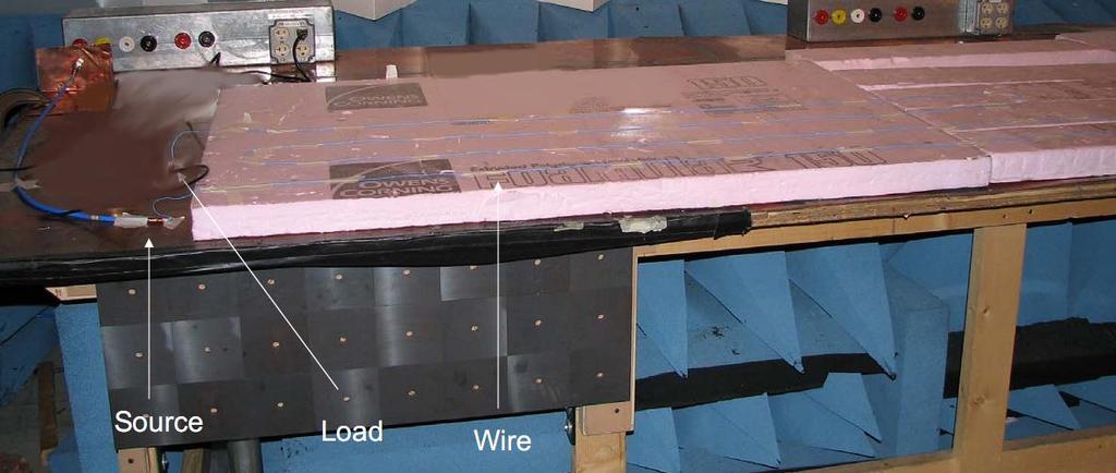
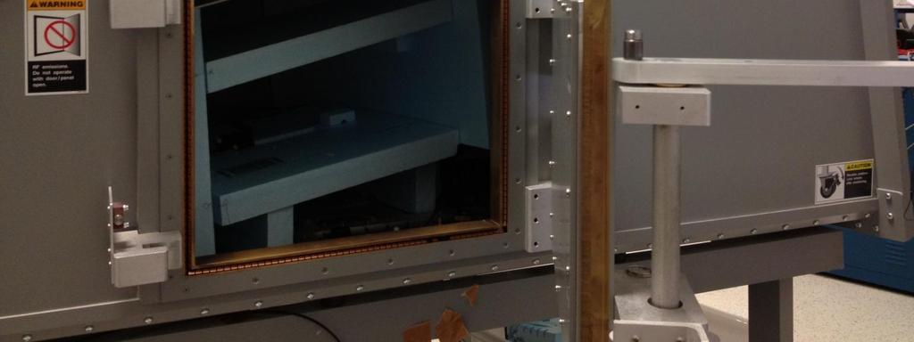
23 Measurement Setup 23
24 Experiment Check A known signal was exciting a known geometry An aerospace standard test setup was used The goal of this simulation is to reproduce the measurement 24

25 Model from 1-30 MHz 25
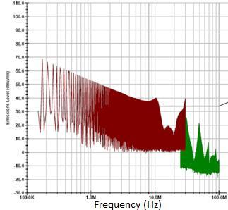
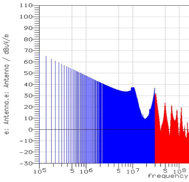
26 Unterminated Wire Measured Simulated 26
27 Comparison Results Frequency Measurement Simulation Difference 150 khz 68 dbµv/m 64 dbµv/m -4 db 1 MHz 52 dbµv/m 47 dbµv/m -5 db 10 MHz 40 dbµv/m 37 dbµv/m -3 db 15 MHz 21 dbµv/m 22 dbµv/m 1 db Minimum (19.7 MHz measured vs 19 MHz simulated) Maximum (30 MHz) 11 dbµv/m 9 dbµv/m 2 db 40 dbµv/m 37 dbµv/m 3 db 27


28 Wire Terminated into 100 Measured Simulated 11 db difference NOT GOOD 28
29 Test Setup Simulation When verifying the accuracy of a simulation tool, one must consider the setup specifics When these specifics change, re-verify! If the goal is to support test data, certain aspects of the test setup (wires, support equipment) should be considered even though it goes against the intent of the test Insight can be gained into test setups by attempting to simulate their results 29


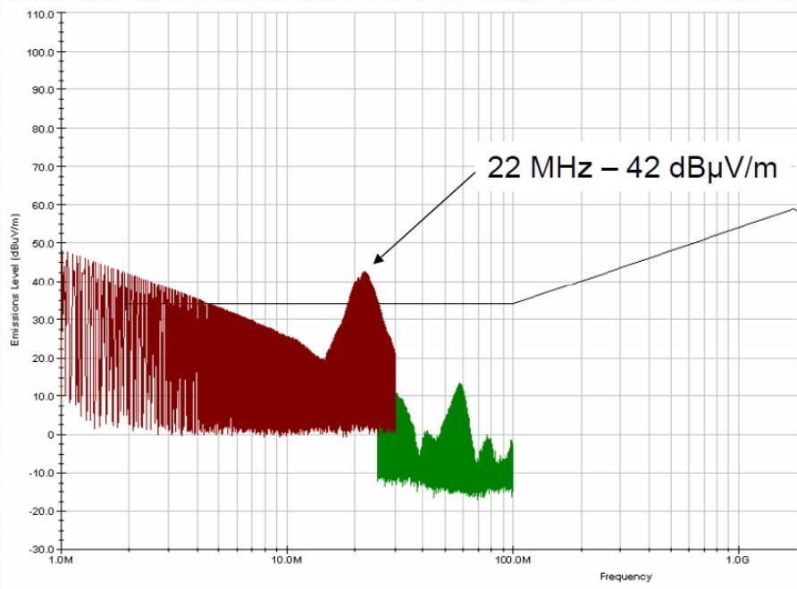
30 Extra Coaxial Cables Added Coax shield for antenna connection Without Cable 22 MHz With Cable 30
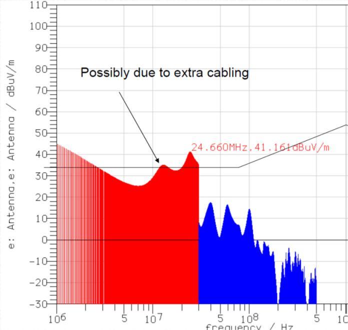
31 Comparison with Coax Cables 31
32 Test Setup Simulation If the goal is to support test data, certain aspects of the test setup (wires, support equipment) should be considered even though it goes against the intent of the test Insight can be gained into test setups by attempting to simulate their results 32
33 Limitations of Measurements Exploring 33

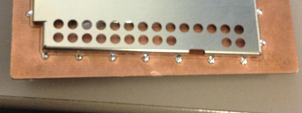
34 PCB Shield 34

35 Field Probe Setup - Simulation 35

36 Plane Wave Excitation 36

37 Electric Field Plot 37
38 Shielding Effectiveness vs. Frequency At Different Locations 38

39 Real World Data? 39
40 Real World Problems Point electric field sensors are typically too large to fit underneath the shield A noise generating circuit attached to a small antenna could be placed inside the shield The circuit would be battery powered Emissions from the circuit could then be measured 40
41 PCB Shield 41
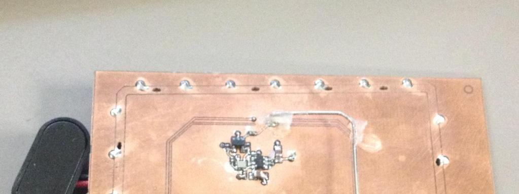
42 Noise Generating Circuit 42

43 Noise Generating Circuit Model 43
44 Shielding Effectiveness vs. Frequency 44
45 Measured Results Shielding Effectiveness = Unshielded-Shielded Unshielded Shielded 45
46 Simulated Results Shielding Effectiveness 46

47 9V Battery Added to Model 47
48 New Results 48
49 Measured Results 49

50 Electric Field Plot at 480 MHz Shield 50

51 Battery Shielded 51
52 Measured Results with Shielded Battery Measured Emissions (dbm) No Shield Full Shield Ambient Frequency (MHz) 52
53 Shielding Effectiveness of PCB Shields There are some investigations that are difficult to use measurement equipment While measurements can be a good way to verify the results of a simulation, simulations can also be used to verify the results of measurements! 53
54 Clues from Measurements Simplifying Simulations: 54


55 Lumped Elements A capacitor is typically represented as a series LRC circuit Parasitic R and L is typically provided on a vendor s datasheet A circuit simulator would require all three of these values in order to produce a correct answer When performing EMC simulations using a full wave solving method, is it important to include these values? 55
56 Experiment Design - ESL A test PCB will be designed such that capacitor impedance can be measured easily by a network analyzer The design will then be simulated with and without capacitor ESL and compared with the measured result 56
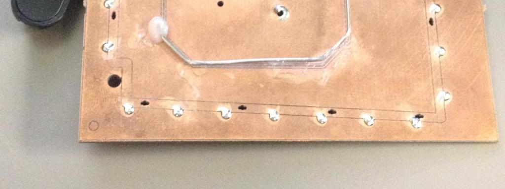
57 Simulation Setup FIT Solver SMA Connector 4 Layer PCB 10 nf 0402 capacitors 57
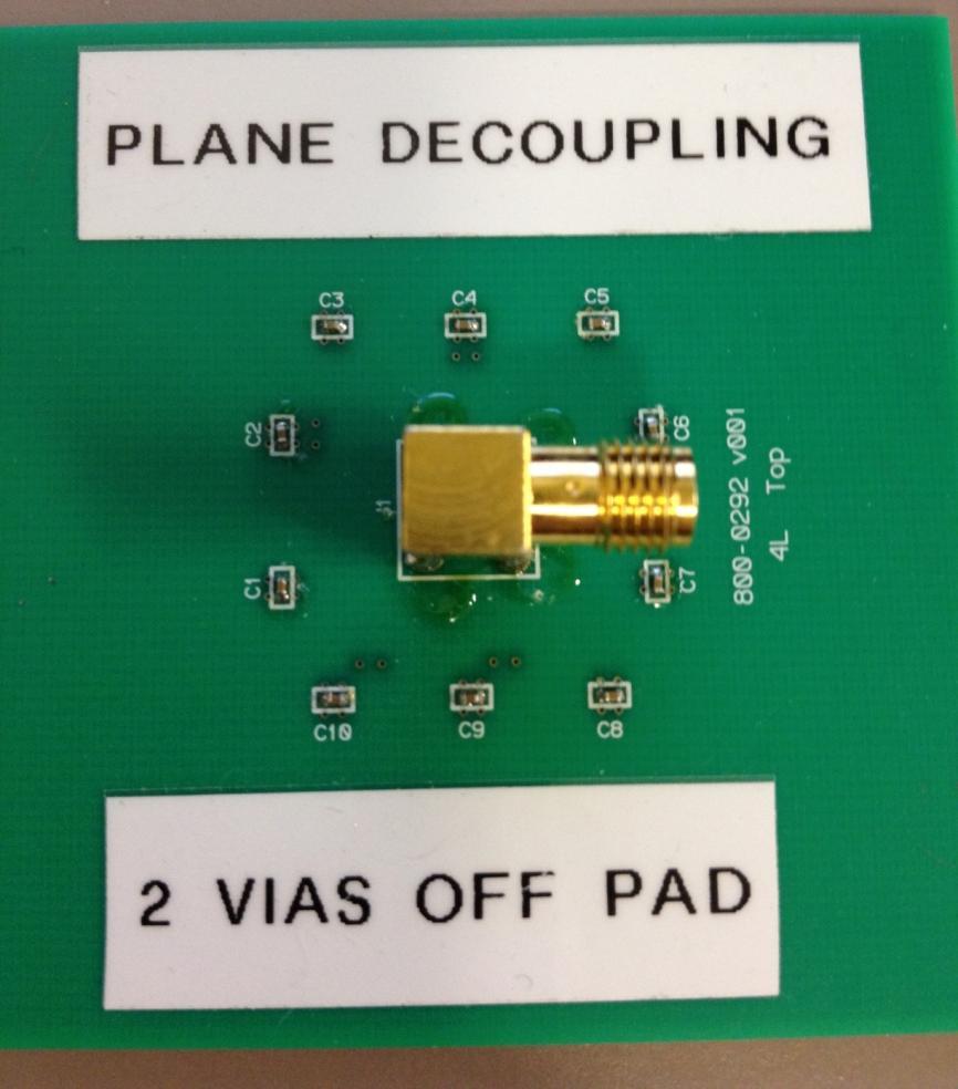
58 Measurement Setup 58
59 Results Measured ESL Dominates Impedance Simulated With Lumped ESL Simulated Without Lumped ESL 59


60 Plates with Ceramic Material in-between Capacitor ESL Leads 60

61 Simulated Capacitor Lumped Element 61
62 Different Simulation Tool 3D finiteelement method solver intended for PCB problems 62
63 Results Simulated With Lumped ESL Measured Simulated Without Lumped ESL What is right for one simulation tool is not always right for another! 63
64 Conclusion - ESL A setup was used that isolated one variable A multi-layer PCB with ceramic SMD capacitors was used for this investigation The results were in harmony with VNA measurements and existing knowledge 64
65 Product Immunity Investigations 65

66 Measurements are the Standard If you want to know if a product will operate normally in a field of 100 V/m at 400 MHz what do you do?. Build the product, then expose it to 100 V/m at 400 MHz and see if it works of course! Can we replace this with a simulation? 66
67 Example Pair of wires Transmitter Receiver What is the optimal configuration for the wire pair in order to carry the signal from the transmitter to the receiver? 67


68 To Twist or Not to Twist? Twisted Separated by 2cm 68
 0-2 -4-6 -8-10 -12-14 -16-18 -20 0 5 10 15 20")
69 To Twist or Not to Twist? S21 Comparision for Wiring Configurations S21 (db) Frequency (MHz) Side by Side Twisted Separated by 2cm 69
70 To Twist or Not to Twist? Measurement/Simulation Comparison Twisted Wires Untwisted Wires Separated by 2cm Measurement Untwisted Measurement Twisted Measurement Separated 70
71 To Twist or Not to Twist? 0 S21 Comparision for Wiring Configurations S21 (db) Frequency (MHz) Side by Side Separated Twisted Does this prove that if wires are separated by 2 cm it won t work? What if you tried this wiring configuration and the communication failed? 71

72 Immunity Simulation Can Still be Valuable Measurements typically provide YES or NO answers Simulations fill in the gaps when conducting troubleshooting investigations Root cause is the circuit weak at this frequency? Or is there a large amount of RF coupling into the circuit caused by a resonance? Is this relating to the test setup or product geometry? Often one can find a fix to the problem while the product is still in the lab. This usually requires cuts and jumpers as a lab fix. If a problem can be reproduced in simulation, then the lab fix can then be simulated along with a production fix. Therefore we have a better idea that the production fix works just as well or better than the lab fix. 72
73 Measurements & Simulations 73

74 Fishing Someone may throw a product layout over the wall and this person would like some simulation done of their product Simulation tools are not very effective at discovering problems More useful information can be obtained by keeping a narrow scope for the analysis Measurements can help bound the investigation 74
75 Actual Product 2 Layer PCB Had sensor malfunctions during immunity testing from MHz Near-field probe investigation has determined that the area near the sensor s data trace is susceptible to EMI 75


76 Near Field Probe Position Initial Position Moved 5cm 76


77 Initial Position Antenna Hidden Moved 5cm 77
78 Magnitude Comparison Initial Position Shifted 5cm 78

79 Antenna 90 with Trace 79
80 Comparison Initial Position Shifted 5cm 80
81 Simulation Setup Replicating a near-field probe investigation would take much time to perform using a simulation tool A diagnostic method that is convenient for laboratory measurements is not always best with simulation A plane wave source will first be used in the model to see if the problem can be duplicated without constructing the near-field antenna 81
82 Simulation Result of Baseline PCB 379 MHz (3pF load assumed at trace ends) Sensor Processor The product had sensor malfunctions during immunity testing from MHz 900 MHz 82

83 Product Product PCB vs. Ideal PCB Ideal 83
84 Comparison Product PCB Ideal PCB 84
85 Make Ideal PCB Product Size Product PCB Product Size Infinite PCB 85


86 Comparison Finite Size Trace near PCB center Finite Size Trace near PCB Edge 86
87 Comparison Results Product PCB Close to Edge Far From Edge 87
88 Conclusion The immunity problem appears to be caused by EM coupling from the edge of the PCB near 900 MHz The Immunity problem would be reduced if the trace is moved away from the PCB edge The problem at 380 MHz was able to be reproduced in the full PCB simulation but the cause has not been found 88
89 Schematic Sensor Processor Resistors will make trace lossy 89

90 Resistors Product Sensor Trace on Ideal PCB 90
91 With and Without Resistors R= 0 R= 47 Resistors appear to do a great job with dampening resonance why is there a problem with this trace? 91

92 Electric Field at 379 MHz on Product PCB Sensor Trace It appears at 379 MHz the power trace is resonant and runs parallel to the sensor trace 379 MHz Power Trace 92
93 Comparison with Power Trace Removed With Power Trace W/O Power Trace 93
94 380 MHz Immunity Problem Upon further investigation it is shown that the immunity problem at 380 MHz is caused by cross coupling from a nearby resonant power trace. Either the resonance can be dampened or the trace can be moved further away from the sensor trace to solve this problem 94
95 Summary Simulation can be used to find the root causes of problems that may exist in products in the testing phase of development by breaking down the problem into a simpler situation These simulations are more effective if guided by measurement data 95
96 EMC Simulation and Measurements EMC simulation and measurement methods both have their strengths and weaknesses but they do not have many weaknesses in common Using EMC simulation and measurement together can provide useful data more than what one or the other can provide by itself. 96
97 References / Acknowledgements Piper, S. and Teune, J., "Verifying Electromagnetic Simulation Results with Measurements," SAE Int. J. Passeng. Cars - Electron. Electr. Syst. 5(1):2012, doi: / Paul, Clayton. Introduction to Electromagnetic Compatibility. Wiley, 2006 Test PCBs were provided by Gentex Corporation Test facilities were provided by Gentex Corporation and Woodward MPC, Inc. 97
Modeling and Simulation of Powertrains for Electric and Hybrid Vehicles
 Modeling and Simulation of Powertrains for Electric and Hybrid Vehicles Dr. Marco KLINGLER PSA Peugeot Citroën Vélizy-Villacoublay, FRANCE marco.klingler@mpsa.com FR-AM-5 Background The automotive context
ELEC 0017: ELECTROMAGNETIC COMPATIBILITY LABORATORY SESSIONS
 Academic Year 2015-2016 ELEC 0017: ELECTROMAGNETIC COMPATIBILITY LABORATORY SESSIONS V. BEAUVOIS P. BEERTEN C. GEUZAINE 1 CONTENTS: EMC laboratory session 1: EMC tests of a commercial Christmas LED light
Chapter 16 PCB Layout and Stackup
 Chapter 16 PCB Layout and Stackup Electromagnetic Compatibility Engineering by Henry W. Ott Foreword The PCB represents the physical implementation of the schematic. The proper design and layout of a printed
ELECTROMAGNETIC COMPATIBILITY HANDBOOK 1. Chapter 8: Cable Modeling
 ELECTROMAGNETIC COMPATIBILITY HANDBOOK 1 Chapter 8: Cable Modeling Related to the topic in section 8.14, sometimes when an RF transmitter is connected to an unbalanced antenna fed against earth ground
Signal and Noise Measurement Techniques Using Magnetic Field Probes
 Signal and Noise Measurement Techniques Using Magnetic Field Probes Abstract: Magnetic loops have long been used by EMC personnel to sniff out sources of emissions in circuits and equipment. Additional
EFFECT OF SHIELDING ON CABLE RF INGRESS MEASUREMENTS LARRY COHEN
 EFFECT OF SHIELDING ON CABLE RF INGRESS MEASUREMENTS LARRY COHEN OVERVIEW Purpose: Examine the common-mode and differential RF ingress levels of 4-pair UTP, F/UTP, and F/FTP cables at an (RJ45) MDI port
Design for Guaranteed EMC Compliance
 Clemson Vehicular Electronics Laboratory Reliable Automotive Electronics Automotive EMC Workshop April 29, 2013 Design for Guaranteed EMC Compliance Todd Hubing Clemson University EMC Requirements and
Understanding the Unintended Antenna Behavior of a Product
 Understanding the Unintended Antenna Behavior of a Product Colin E. Brench Southwest Research Institute Electromagnetic Compatibility Research and Testing colin.brench@swri.org Radiating System Source
Testing for EMC Compliance: Approaches and Techniques October 12, 2006
 : Approaches and Techniques October 12, 2006 Ed Nakauchi EMI/EMC/ESD/EMP Consultant Emulex Corporation 1 Outline Discuss EMC Basics & Physics Fault Isolation Techniques Tools & Techniques Correlation Analyzer
EMC cases study. Antonio Ciccomancini Scogna, CST of America CST COMPUTER SIMULATION TECHNOLOGY
 EMC cases study Antonio Ciccomancini Scogna, CST of America antonio.ciccomancini@cst.com Introduction Legal Compliance with EMC Standards without compliance products can not be released to the market Failure
EMC review for Belle II (Grounding & shielding plans) PXD DEPFET system
 PXD DEPFET system") EMC review for Belle II (Grounding & shielding plans) PXD DEPFET system Outline 1. Introduction 2. Grounding strategy Implementation aspects 3. Noise emission issues Test plans 4. Noise immunity issues
EMC review for Belle II (Grounding & shielding plans) PXD DEPFET system Outline 1. Introduction 2. Grounding strategy Implementation aspects 3. Noise emission issues Test plans 4. Noise immunity issues
10 Safety earthing/grounding does not help EMC at RF
 1of 6 series Webinar #3 of 3, August 28, 2013 Grounding, Immunity, Overviews of Emissions and Immunity, and Crosstalk Contents of Webinar #3 Topics 1 through 9 were covered by the previous two webinars
Electromagnetic Compatibility
 Electromagnetic Compatibility Introduction to EMC International Standards Measurement Setups Emissions Applications for Switch-Mode Power Supplies Filters 1 What is EMC? A system is electromagnetic compatible
Antenna Matching Within an Enclosure Part II: Practical Techniques and Guidelines
 Antenna Matching Within an Enclosure Part II: Practical Techniques and Guidelines By Johnny Lienau, RF Engineer June 2012 Antenna selection and placement can be a difficult task, and the challenges of
EMC Simulation of Consumer Electronic Devices
 of Consumer Electronic Devices By Andreas Barchanski Describing a workflow for the EMC simulation of a wireless router, using techniques that can be applied to a wide range of consumer electronic devices.
Common myths, fallacies and misconceptions in Electromagnetic Compatibility and their correction.
 Common myths, fallacies and misconceptions in Electromagnetic Compatibility and their correction. D. A. Weston EMC Consulting Inc 22-3-2010 These are some of the commonly held beliefs about EMC which are
Debugging EMI Using a Digital Oscilloscope. Dave Rishavy Product Manager - Oscilloscopes
 Debugging EMI Using a Digital Oscilloscope Dave Rishavy Product Manager - Oscilloscopes 06/2009 Nov 2010 Fundamentals Scope Seminar of DSOs Signal Fidelity 1 1 1 Debugging EMI Using a Digital Oscilloscope
TECHNICAL REPORT: CVEL Special Considerations for PCB Heatsink Radiation Estimation. Xinbo He and Dr. Todd Hubing Clemson University
 TECHNICAL REPORT: CVEL-11-27 Special Considerations for PCB Heatsink Radiation Estimation Xinbo He and Dr. Todd Hubing Clemson University May 4, 211 Table of Contents Abstract... 3 1. Configuration for
11 Myths of EMI/EMC ORBEL.COM. Exploring common misconceptions and clarifying them. MYTH #1: EMI/EMC is black magic.
 11 Myths of EMI/EMC Exploring common misconceptions and clarifying them By Ed Nakauchi, Technical Consultant, Orbel Corporation What is a myth? A myth is defined as a popular belief or tradition that has
Investigation of Cavity Resonances in an Automobile
 Investigation of Cavity Resonances in an Automobile Haixiao Weng, Daryl G. Beetner, Todd H. Hubing, and Xiaopeng Dong Electromagnetic Compatibility Laboratory University of Missouri-Rolla Rolla, MO 65409,
EMC Near-field Probes + Wideband Amplifier
 1 Introduction The H20, H10, H5 and E5 are magnetic field (H) and electric field (E) probes for radiated emissions EMC precompliance measurements. The probes are used in the near field of sources of electromagnetic
LISN UP Application Note
 LISN UP Application Note What is the LISN UP? The LISN UP is a passive device that enables the EMC Engineer to easily distinguish between differential mode noise and common mode noise. This will enable
Influence of Termination Impedance on conducted Emissions in Automotive High Voltage Networks
 Influence of Termination Impedance on conducted Emissions in Automotive High Voltage Networks M. Reuter *, S. Tenbohlen, W. Koehler Institute of Power Transmission and High Voltage Technology (IEH), University
Large E Field Generators in Semi-anechoic Chambers for Full Vehicle Immunity Testing
 Large E Field Generators in Semi-anechoic Chambers for Full Vehicle Immunity Testing Vince Rodriguez ETS-Lindgren, Inc. Abstract Several standards recommend the use of transmission line systems (TLS) as
Localization and Identifying EMC interference Sources of a Microwave Transmission Module
 Localization and Identifying EMC interference Sources of a Microwave Transmission Module Ph. Descamps 1, G. Ngamani-Njomkoue 2, D. Pasquet 1, C. Tolant 2, D. Lesénéchal 1 and P. Eudeline 2 1 LaMIPS, Laboratoire
Trees, vegetation, buildings etc.
 EMC Measurements Test Site Locations Open Area (Field) Test Site Obstruction Free Trees, vegetation, buildings etc. Chamber or Screened Room Smaller Equipments Attenuate external fields (about 100dB) External
AN IMPROVED MODEL FOR ESTIMATING RADIATED EMISSIONS FROM A PCB WITH ATTACHED CABLE
 Progress In Electromagnetics Research M, Vol. 33, 17 29, 2013 AN IMPROVED MODEL FOR ESTIMATING RADIATED EMISSIONS FROM A PCB WITH ATTACHED CABLE Jia-Haw Goh, Boon-Kuan Chung *, Eng-Hock Lim, and Sheng-Chyan
Practical Considerations for Radiated Immunities Measurement using ETS-Lindgren EMC Probes
 Practical Considerations for Radiated Immunities Measurement using ETS-Lindgren EMC Probes Detectors/Modulated Field ETS-Lindgren EMC probes (HI-6022/6122, HI-6005/6105, and HI-6053/6153) use diode detectors
Solution of EMI Problems from Operation of Variable-Frequency Drives
 Pacific Gas and Electric Company Solution of EMI Problems from Operation of Variable-Frequency Drives Background Abrupt voltage transitions on the output terminals of a variable-frequency drive (VFD) are
Understanding and Optimizing Electromagnetic Compatibility in Switchmode Power Supplies
 Understanding and Optimizing Electromagnetic Compatibility in Switchmode Power Supplies 1 Definitions EMI = Electro Magnetic Interference EMC = Electro Magnetic Compatibility (No EMI) Three Components
Top Ten EMC Problems
 Top Ten EMC Problems presented by: Kenneth Wyatt Sr. EMC Consultant EMC & RF Design, Troubleshooting, Consulting & Training 10 Northern Boulevard, Suite 1 Amherst, New Hampshire 03031 +1 603 578 1842 www.silent-solutions.com
Suppression Techniques using X2Y as a Broadband EMI Filter IEEE International Symposium on EMC, Boston, MA
 Suppression Techniques using X2Y as a Broadband EMI Filter Jim Muccioli Tony Anthony Dave Anthony Dale Sanders X2Y Attenuators, LLC Erie, PA 16506-2972 www.x2y.com Email: x2y@x2y.com Bart Bouma Yageo/Phycomp
Technology in Balance
 Technology in Balance A G1 G2 B Basic Structure Comparison Regular capacitors have two plates or electrodes surrounded by a dielectric material. There is capacitance between the two conductive plates within
EMI AND BEL MAGNETIC ICM
 EMI AND BEL MAGNETIC ICM ABSTRACT Electromagnetic interference (EMI) in a local area network (LAN) system is a common problem that every LAN system designer faces, and it is a growing problem because the
Application Note 5525
 Using the Wafer Scale Packaged Detector in 2 to 6 GHz Applications Application Note 5525 Introduction The is a broadband directional coupler with integrated temperature compensated detector designed for
Internal Model of X2Y Chip Technology
 Internal Model of X2Y Chip Technology Summary At high frequencies, traditional discrete components are significantly limited in performance by their parasitics, which are inherent in the design. For example,
OPEN TEM CELLS FOR EMC PRE-COMPLIANCE TESTING
 1 Introduction Radiated emission tests are typically carried out in anechoic chambers, using antennas to pick up the radiated signals. Due to bandwidth limitations, several antennas are required to cover
Understanding, measuring, and reducing output noise in DC/DC switching regulators
 Understanding, measuring, and reducing output noise in DC/DC switching regulators Practical tips for output noise reduction Katelyn Wiggenhorn, Applications Engineer, Buck Switching Regulators Robert Blattner,
Novel Modeling Strategy for a BCI set-up applied in an Automotive Application
 Novel Modeling Strategy for a BCI set-up applied in an Automotive Application An industrial way to use EM simulation tools to help Hardware and ASIC designers to improve their designs for immunity tests.
Introduction to Electromagnetic Compatibility
 Introduction to Electromagnetic Compatibility Second Edition CLAYTON R. PAUL Department of Electrical and Computer Engineering, School of Engineering, Mercer University, Macon, Georgia and Emeritus Professor
OPEN TEM CELLS FOR EMC PRE-COMPLIANCE TESTING
 1 Introduction Radiated emission tests are typically carried out in anechoic chambers, using antennas to pick up the radiated signals. Due to bandwidth limitations, several antennas are required to cover
Class-D Audio Power Amplifiers: PCB Layout For Audio Quality, EMC & Thermal Success (Home Entertainment Devices)
") Class-D Audio Power Amplifiers: PCB Layout For Audio Quality, EMC & Thermal Success (Home Entertainment Devices) Stephen Crump http://e2e.ti.com Audio Power Amplifier Applications Audio and Imaging Products
Class-D Audio Power Amplifiers: PCB Layout For Audio Quality, EMC & Thermal Success (Home Entertainment Devices) Stephen Crump http://e2e.ti.com Audio Power Amplifier Applications Audio and Imaging Products
Improving the immunity of sensitive analogue electronics
 Improving the immunity of sensitive analogue electronics T.P.Jarvis BSc CEng MIEE MIEEE, I.R.Marriott BEng, EMC Journal 1997 Introduction The art of good analogue electronics design has appeared to decline
Analogue circuit design for RF immunity
 Analogue circuit design for RF immunity By EurIng Keith Armstrong, C.Eng, FIET, SMIEEE, www.cherryclough.com First published in The EMC Journal, Issue 84, September 2009, pp 28-32, www.theemcjournal.com
Applications of 3D Electromagnetic Modeling in Magnetic Recording: ESD and Signal Integrity
 Applications of 3D Electromagnetic Modeling in Magnetic Recording: ESD and Signal Integrity CST NORTH AMERICAN USERS FORUM John Contreras 1 and Al Wallash 2 Hitachi Global Storage Technologies 1. San Jose
High-Performance Electronic Design: Predicting Electromagnetic Interference
 White Paper High-Performance Electronic Design: In designing electronics in today s highly competitive markets, meeting requirements for electromagnetic compatibility (EMC) presents a major risk factor,
Seattle & Oregon Chapters "New X2Y Filter Technology Emerges as Single Component Solution For Noise Suppression
 "New X2Y Filter Technology Emerges as Single Component Solution For Noise Suppression Presentation: approx. 60 min Introduction: A new capacitive technology introduced by X2Y Attenuators LLC, Erie, Pa.,
APPLICATION NOTE FOR PA.710A ANTENNA INTEGRATION
 APPLICATION NOTE FOR PA.710A ANTENNA INTEGRATION APN-11-8-001/B Page 1 of 22 1. TABLE OF CONTENTS 1. TABLE OF CONTENTS... 2 2. BASICS... 4 3. APPLICATIONS... 5 4. IMPEDANCE... 5 5. BANDWIDTH... 5 6. GAIN...
150Hz to 1MHz magnetic field coupling to a typical shielded cable above a ground plane configuration
 150Hz to 1MHz magnetic field coupling to a typical shielded cable above a ground plane configuration D. A. Weston Lowfreqcablecoupling.doc 7-9-2005 The data and information contained within this report
Techniques to reduce electromagnetic noise produced by wired electronic devices
 Rok / Year: Svazek / Volume: Číslo / Number: Jazyk / Language 2016 18 5 EN Techniques to reduce electromagnetic noise produced by wired electronic devices - Tomáš Chvátal xchvat02@stud.feec.vutbr.cz Faculty
OPEN SOURCE CABLE MODELS FOR EMI SIMULATIONS
 OPEN SOURCE CABLE MODELS FOR EMI SIMULATIONS S. Greedy 1, C. Smartt 1, D. W. P. Thomas 1. 1 : George Green Institute for Electromagnetics Research, Department of Electrical and Electronic Engineering,
Top Ten EMC Problems & EMC Troubleshooting Techniques by Kenneth Wyatt, DVD, Colorado Springs Rev. 1, Feb 26, 2007
 EMC Engineering Top Ten EMC Problems & EMC Troubleshooting Techniques by Kenneth Wyatt, DVD, Colorado Springs Rev. 1, Feb 26, 2007 1a. Ground Impedance The overwhelming majority of high-frequency problems,
Designing Your EMI Filter
 The Engineer s Guide to Designing Your EMI Filter TABLE OF CONTENTS Introduction Filter Classifications Why Do We Need EMI Filters Filter Configurations 2 2 3 3 How to Determine Which Configuration to
ENT-AN0098 Application Note. Magnetics Guide. June 2018
 ENT-AN0098 Application Note Magnetics Guide June 2018 Contents 1 Revision History... 1 1.1 Revision 2.2... 1 1.2 Revision 2.1... 1 1.3 Revision 2.0... 1 1.4 Revision 1.2... 1 1.5 Revision 1.1... 1 1.6
Ileana-Diana Nicolae ICMET CRAIOVA UNIVERSITY OF CRAIOVA MAIN BUILDING FACULTY OF ELECTROTECHNICS
 The Designing, Realization and Testing of a Network Filter used to Reduce Electromagnetic Disturbances and to Improve the EMI for Static Switching Equipment Petre-Marian Nicolae Ileana-Diana Nicolae George
AP7301 ELECTROMAGNETIC INTERFERENCE AND COMPATIBILITY L T P C COURSE OBJECTIVES:
 AP7301 ELECTROMAGNETIC INTERFERENCE AND COMPATIBILITY L T P C 3 0 0 3 COURSE OBJECTIVES: To understand the basics of EMI To study EMI Sources To understand EMI problems To understand Solution methods in
Overview of the ATLAS Electromagnetic Compatibility Policy
 Overview of the ATLAS Electromagnetic Compatibility Policy G. Blanchot CERN, CH-1211 Geneva 23, Switzerland Georges.Blanchot@cern.ch Abstract The electromagnetic compatibility of ATLAS electronic equipments
Reducing Motor Drive Radiated Emissions
 Volume 2, Number 2, April, 1996 Application Note 107 Donald E. Fulton Reducing Motor Drive Radiated Emissions Introduction This application note discusses radiated emissions (30 Mhz+) of motor drives and
Split Planes in Multilayer PCBs
 by Barry Olney coulmn BEYOND DESIGN Split Planes in Multilayer PCBs Creating split planes or isolated islands in the copper planes of multilayer PCBs at first seems like a good idea. Today s high-speed
Bias-T Design Considerations for the LWA Brian Hicks and Bill Erickson May 21, 2008
 Bias-T Design Considerations for the LWA Brian Hicks and Bill Erickson May 21, 2008 The strawman design document [1] for the LWA suggests that the Front End Electronics (FEE) could be powered through the
AN-1011 APPLICATION NOTE
 AN-111 APPLICATION NOTE One Technology Way P.O. Box 916 Norwood, MA 262-916, U.S.A. Tel: 781.329.47 Fax: 781.461.3113 www.analog.com EMC Protection of the AD715 by Holger Grothe and Mary McCarthy INTRODUCTION
LTE Small-Cell Base Station Antenna Matched for Maximum Efficiency
 Application Note LTE Small-Cell Base Station Antenna Matched for Maximum Efficiency Overview When designing antennas for base stations and mobile devices, an essential step of the design process is to
"Natural" Antennas. Mr. Robert Marcus, PE, NCE Dr. Bruce C. Gabrielson, NCE. Security Engineering Services, Inc. PO Box 550 Chesapeake Beach, MD 20732
 Published and presented: AFCEA TEMPEST Training Course, Burke, VA, 1992 Introduction "Natural" Antennas Mr. Robert Marcus, PE, NCE Dr. Bruce C. Gabrielson, NCE Security Engineering Services, Inc. PO Box
The shunt capacitor is the critical element
 Accurate Feedthrough Capacitor Measurements at High Frequencies Critical for Component Evaluation and High Current Design A shielded measurement chamber allows accurate assessment and modeling of low pass
IEEE RTPGE Automotive Datalinks over Twisted Quad Cabling
 Automotive Datalinks over Twisted Quad Cabling T. Müller, G. Armbrecht, S. Kunz Rosenberger Hochfrequenztechnik GmbH & Co. KG Outline Automotive Datalinks over Twisted Quad Cabling Twisted Quad fundamentals
T + T /13/$ IEEE 236. the inverter s input impedances on the attenuation of a firstorder
 Emulation of Conducted Emissions of an Automotive Inverter for Filter Development in HV Networks M. Reuter *, T. Friedl, S. Tenbohlen, W. Köhler Institute of Power Transmission and High Voltage Technology
Chapter 5 Electromagnetic interference in flash lamp pumped laser systems
 Chapter 5 Electromagnetic interference in flash lamp pumped laser systems This chapter presents the analysis and measurements of radiated near and far fields, and conducted emissions due to interconnects
Corcom Product Guide. Introduction
 Introduction Corcom brand SignalSentry filtered modular jack series product combines different levels of filtering with and modular jacks to solve signal line noise problems and crosstalk. Corcom brand
1 Introduction. Webinar sponsored by: Cost-effective uses of close-field probing. Contents
 1of 8 Close-field probing series Webinar #1 of 2, Cost-effective uses of close-field probing in every project stage: emissions, immunity and much more Webinar sponsored by: Keith Armstrong CEng, EurIng,
4. THEORETICAL: EMISSION AND SUSCEPTIBILITY. pressure sensor, i.e, via printed-circuit board tracks, internal wiring which acts as an
 4. THEORETICAL: EMISSION AND SUSCEPTIBILITY There are many ways for the electromagnetic-interference to be coupled to the pressure sensor, i.e, via printed-circuit board tracks, internal wiring which acts
Course Introduction. Content: 19 pages 3 questions. Learning Time: 30 minutes
 Course Introduction Purpose: This course discusses techniques that can be applied to reduce problems in embedded control systems caused by electromagnetic noise Objectives: Gain a basic knowledge about
Simulation and Design of Printed Circuit Boards Utilizing Novel Embedded Capacitance Material
 Simulation and Design of Printed Circuit Boards Utilizing Novel Embedded Capacitance Material April 28, 2010 Yu Xuequan, Yanhang, Zhang Gezi, Wang Haisan Huawei Technologies CO., LTD. Shanghai, China Tony_yu@huawei.com
Common myths, fallacies and misconceptions in Electromagnetic Compatibility and their correction.
 Common myths, fallacies and misconceptions in Electromagnetic Compatibility and their correction. D. A. Weston EMC Consulting Inc 15-3-2013 1) First topic an introduction These are some of the commonly
ELEC Course Objectives/Proficiencies
 Lecture 1 -- to identify (and list examples of) intentional and unintentional receivers -- to list three (broad) ways of reducing/eliminating interference -- to explain the differences between conducted/radiated
Advanced Test Equipment Rentals ATEC (2832)
") Established 1981 Advanced Test Equipment Rentals www.atecorp.com 800-404-ATEC (2832) A.H. Systems Model Active Monopole Antennas Active Monopole Antenna Series Operation Manual 1 TABLE OF CONTENTS INTRODUCTION
Established 1981 Advanced Test Equipment Rentals www.atecorp.com 800-404-ATEC (2832) A.H. Systems Model Active Monopole Antennas Active Monopole Antenna Series Operation Manual 1 TABLE OF CONTENTS INTRODUCTION
PLEASE NOTE! THIS IS PARALLEL PUBLISHED VERSION / SELF-ARCHIVED VERSION OF THE OF THE ORIGINAL ARTICLE
 PLEASE NOTE! THIS IS PARALLEL PUBLISHED VERSION / SELF-ARCHIVED VERSION OF THE OF THE ORIGINAL ARTICLE This is an electronic reprint of the original article. This version may differ from the original in
Test and Measurement for EMC
 Test and Measurement for EMC Bogdan Adamczyk, Ph.D., in.c.e. Professor of Engineering Director of the Electromagnetic Compatibility Center Grand Valley State University, Michigan, USA Ottawa, Canada July
MINIMIZING EMI EFFECTS DURING PCB LAYOUT OF Z8/Z8PLUS CIRCUITS
 APPLICATION NOTE MINIMIZING EMI EFFECTS DURING PCB LAYOUT OF Z8/Z8PLUS CIRCUITS INTRODUCTION The Z8/Z8Plus families have redefined ease-of-use by being the simplest 8-bit microcontrollers to program. Combined
EMC Overview. What is EMC? Why is it Important? Case Studies. Examples of calculations used in EMC. EMC Overview 1
 EMC Overview What is EMC? Why is it Important? Case Studies. Examples of calculations used in EMC. EMC Overview 1 What Is EMC? Electromagnetic Compatibility (EMC): The process of determining the interaction
Heat sink. Insulator. µp Package. Heatsink is shown with parasitic coupling.
 X2Y Heatsink EMI Reduction Solution Summary Many OEM s have EMI problems caused by fast switching gates of IC devices. For end products sold to consumers, products must meet FCC Class B regulations for
INVENTION DISCLOSURE- ELECTRONICS SUBJECT MATTER IMPEDANCE MATCHING ANTENNA-INTEGRATED HIGH-EFFICIENCY ENERGY HARVESTING CIRCUIT
 INVENTION DISCLOSURE- ELECTRONICS SUBJECT MATTER IMPEDANCE MATCHING ANTENNA-INTEGRATED HIGH-EFFICIENCY ENERGY HARVESTING CIRCUIT ABSTRACT: This paper describes the design of a high-efficiency energy harvesting
EMC and New Technologies in Automotive Systems
 EMC and New Technologies in Automotive Systems Mark Steffka Email: msteffka@umd.umich.edu University of Michigan Dearborn Electrical and Computer Engineering Department EMC & New Technologies in Auto Systems
APPLICATION NOTE FOR PA.710.A ANTENNA INTEGRATION
 APPLICATION NOTE FOR PA.710.A ANTENNA INTEGRATION APN-13-8-005/B/NB Page 1 of 17 1. TABLE OF CONTENTS 1. TABLE OF CONTENTS... 2 2. BASICS... 3 3. APPLICATIONS... 4 4. IMPEDANCE... 4 5. BANDWIDTH... 4 6.
Alternative Coupling Method for Immunity Testing of Power Grid Protection Equipment
 Alternative Coupling Method for Immunity Testing of Power Grid Protection Equipment Christian Suttner*, Stefan Tenbohlen Institute of Power Transmission and High Voltage Technology (IEH), University of
AUTOMOTIVE ELECTROMAGNETIC COMPATIBILITY (EMC)
") AUTOMOTIVE ELECTROMAGNETIC COMPATIBILITY (EMC) AUTOMOTIVE ELECTROMAGNETIC COMPATIBILITY (EMC) Terence Rybak Mark Steffka KLUWER ACADEMIC PUBLISHERS NEW YORK, BOSTON, DORDRECHT, LONDON, MOSCOW ebook ISBN:
AUTOMOTIVE ELECTROMAGNETIC COMPATIBILITY (EMC) AUTOMOTIVE ELECTROMAGNETIC COMPATIBILITY (EMC) Terence Rybak Mark Steffka KLUWER ACADEMIC PUBLISHERS NEW YORK, BOSTON, DORDRECHT, LONDON, MOSCOW ebook ISBN:
Electromagnetic Compatibility ( EMC )
") Electromagnetic Compatibility ( EMC ) Introduction EMC Testing 1-2 -1 Agenda System Radiated Interference Test System Conducted Interference Test 1-2 -2 System Radiated Interference Test Open-Area Test
Electromagnetic Compatibility ( EMC ) Introduction EMC Testing 1-2 -1 Agenda System Radiated Interference Test System Conducted Interference Test 1-2 -2 System Radiated Interference Test Open-Area Test
Design Considerations for Highly Integrated 3D SiP for Mobile Applications
 Design Considerations for Highly Integrated 3D SiP for Mobile Applications FDIP, CA October 26, 2008 Joungho Kim at KAIST joungho@ee.kaist.ac.kr http://tera.kaist.ac.kr Contents I. Market and future direction
Uncertainties of immunity measurements
 Uncertainties of immunity measurements DTI-NMSPU project R2.2b1 Annex A Description of the circuit model (conducted immunity) Annex A Description of the circuit model (conducted immunity) Annex A Description
1000BASE-T1 EMC Test Specification for Common Mode Chokes
 IEEE 1000BASE-T1 EMC Test Specification for Common Mode Chokes Version 1.0 Author & Company Dr. Bernd Körber, FTZ Zwickau Title 1000BASE-T1 EMC Test Specification for Common Mode Chokes Version 1.0 Date
Technical Report Printed Circuit Board Decoupling Capacitor Performance For Optimum EMC Design
 Technical Report Printed Circuit Board Decoupling Capacitor Performance For Optimum EMC Design Bruce Archambeault, Ph.D. Doug White Personal Systems Group Electromagnetic Compatibility Center of Competency
A VIEW OF ELECTROMAGNETIC LIFE ABOVE 100 MHz
 A VIEW OF ELECTROMAGNETIC LIFE ABOVE 100 MHz An Experimentalist's Intuitive Approach Lothar O. (Bud) Hoeft, PhD Consultant, Electromagnetic Effects 5012 San Pedro Ct., NE Albuquerque, NM 87109-2515 (505)
IC Decoupling and EMI Suppression using X2Y Technology
 IC Decoupling and EMI Suppression using X2Y Technology Summary Decoupling and EMI suppression of ICs is a complex system level engineering problem complicated by the desire for faster switching gates,
Chapter 12 Digital Circuit Radiation. Electromagnetic Compatibility Engineering. by Henry W. Ott
 Chapter 12 Digital Circuit Radiation Electromagnetic Compatibility Engineering by Henry W. Ott Forward Emission control should be treated as a design problem from the start, it should receive the necessary
University of Pennsylvania Moore School of Electrical Engineering ESE319 Electronic Circuits - Modeling and Measurement Techniques
 University of Pennsylvania Moore School of Electrical Engineering ESE319 Electronic Circuits - Modeling and Measurement Techniques 1. Introduction. Students are often frustrated in their attempts to execute
7. EMV Fachtagung. EMV-gerechtes Filterdesign. 23. April 2009, TU-Graz. Dr. Gunter Winkler (TU Graz) Dr. Bernd Deutschmann (Infineon Technologies AG)
 Dr. Bernd Deutschmann (Infineon Technologies AG)") 7. EMV Fachtagung 23. April 2009, TU-Graz EMV-gerechtes Filterdesign Dr. Gunter Winkler (TU Graz) Dr. Bernd Deutschmann (Infineon Technologies AG) Page 1 Agenda Filter design basics Filter Attenuation
7. EMV Fachtagung 23. April 2009, TU-Graz EMV-gerechtes Filterdesign Dr. Gunter Winkler (TU Graz) Dr. Bernd Deutschmann (Infineon Technologies AG) Page 1 Agenda Filter design basics Filter Attenuation
Common Impedance Shield Coupling
 Common Impedance Shield Coupling When a coaxial cable is used at low frequencies and the shield is grounded at both ends, V R I IN S S The shield serves two functions: 1. the return conductor for the signal;
Prof. dr. ir. Johan CATRYSSE
 EMC: How to handle large machinery Prof. dr. ir. Johan CATRYSSE FMEC, KHBO, Oostende (BE) MICAS/ESAT, KULeuven (BE) 1 Overview 2 Large Machinery EMC Directive and Harmonised Standards TEMCA2 project Conducted
Todd H. Hubing Michelin Professor of Vehicular Electronics Clemson University
 Essential New Tools for EMC Diagnostics and Testing Todd H. Hubing Michelin Professor of Vehicular Electronics Clemson University Where is Clemson University? Clemson, South Carolina, USA Santa Clara Valley
Electromagnetic Compliance: Pre-Compliance Test Basics October 19, 2017
 Electromagnetic Compliance: Pre-Compliance Test Basics October 19, 2017 Today s products are subjected to more standardized test requirements than ever before. These standards (UL, CE, and others) ensure
by: Shaoyong Wang, Yuming Song Executive Summary I. PROBLEM STATEMENT
 A NEAR-FIELD 2.4GHZ RING ANTENNA FOR HIGH DATA RATE AND HIGH SECURITY DATA TRANSMISSION IN SHORT RANGE FOR ROTATIONAL JOINT Advanced Development Engineering Team, Appliances, Shanghai, P. R. China by: