Seattle & Oregon Chapters "New X2Y Filter Technology Emerges as Single Component Solution For Noise Suppression
|
|
|
- Rose Rodgers
- 6 years ago
- Views:
Transcription

1 "New X2Y Filter Technology Emerges as Single Component Solution For Noise Suppression Presentation: approx. 60 min Introduction: A new capacitive technology introduced by X2Y Attenuators LLC, Erie, Pa., can overcome the limitations of currently available signal-integrity solutions by reducing parts count while enhancing performance. It also opens the door to multi-sourced solutions. The X2Y technology is not a capacitor per se, but rather an architecture that can be used to manufacture a variety of devices, including capacitors, decouplers, transient voltage suppressors, and filters. * *Quote from Capacitive Technology Filters And Decouples With Fewer Parts by David Morrison, Electronic Design Magazine, February 7, 2000 November 27,
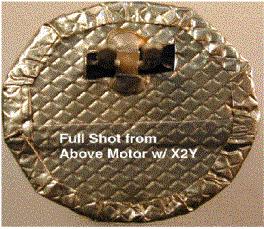
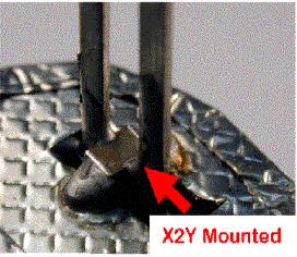
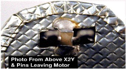
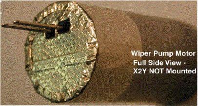
2 Topics Covered: An update on the U.S. and European IC standards for Emissions and Immunity. Real world applications and test results of X2Y technology. A single X2Y device is used to suppress noise in small DC motors, replacing up to seven components currently used for EMI, including inductors, ferrites and standard capacitors. RJ 45 Connectors. Higher operating frequencies are bringing to light many of the shortfalls in today filter components, the broadband characteristics of X2Y Technology are offered as a possible solution. Speaker: Jim Muccioli 2
3 Topics Covered: An update on the U.S. and European IC standards for Emissions and Immunity. Real world applications and test results of X2Y technology. A single X2Y device is used to suppress noise in small DC motors, replacing up to seven components currently used for EMI, including inductors, ferrites and standard capacitors. RJ 45 Connectors. Higher operating frequencies are bringing to light many of the shortfalls in today filter components, the broadband characteristics of X2Y Technology are offered as a possible solution. 3
4 U.S. and European IC EMC Standards Document Title: PROJECT: DOCUMENT: SAE # Integrated circuits- Universal test board for EMC measurement - Part 1: General and definitions IEC Ed A/584/CDV J Integrated circuits - Measurement of electromagnetic emission, 150 KHz to 1 GHz - Part 2: Measurement of radiated emissions, TEM-cell method IEC Ed A/532/CD J Integrated circuits - Measurement of electromagnetic emission, 150 KHz to 1 GHz - Part 3: Measurement of radiated emissions, loop antenna method Integrated circuits - Measurement of electromagnetic emissions, 150 KHz to 1 GHz - Part 4: Measurement of conducted emissions, 1 ohm/150 ohm direct coupling method Integrated circuits - Measurement of electromagnetic emissions, 150 KHz to 1 GHz - Part 5: Measurement of conducted emissions, workbench faraday cage method Integrated circuits - Measurement of electromagnetic emissions, 150 KHz to 1 GHz - Part 6: Measurement of conducted emission, magnetic probe method Integrated circuits- Measurement of electromagnetic immunity -conducted RF disturbance by direct RF power injection IEC TS Ed.1.0 IEC Ed.1.0 IEC Ed.1.0 IEC Ed.1.0 IEC f2 Ed A/532/CD J A/566/CD 47A/567/CD 47A/588/CD 47A/529/NP Integrated circuits- Measurement of electromagnetic immunity -narrowband disturbance by bulk current injection (BCI) IEC f1 Ed A/526/NP Integrated circuits - Measurement of electromagnetic immunity IEC f3 Ed A/542/NP 4
5 SUB-COMMITTEE N0. 47A: INTEGRATED CIRCUITS Participants by Country: France Japan Poland Netherlands United Kingdom USA Participants by Company: Hitachi Infineon ITE Motorola NEC Okayama University Philips Politecnico di Torino Siemens Automotive Texas Instrument 5
6 Topics Covered: An update on the U.S. and European IC standards for Emissions and Immunity. Real world applications and test results of X2Y technology. A single X2Y device is used to suppress noise in small DC motors, replacing up to seven components currently used for EMI, including inductors, ferrites and standard capacitors. RJ 45 Connectors. Higher operating frequencies are bringing to light many of the shortfalls in today filter components, the broadband characteristics of X2Y Technology are offered as a possible solution. 6
7 3/8 0 /,8 07!: : ,
8 3/8 0 /,8 07!:
9 9
10 3/8 0 /,8 07!: ;0/!071472, ,3 0/$ 0 / 3 10
11 // 9 43, $2, , 08 #,/,90/%089425,7 843 ;8',7 4:8!
12 Technology in Balance A G1 G2 B 12
13 Basic Structure Comparison Regular capacitors have two plates or electrodes surrounded by a dielectric material. There is capacitance between the two conductive plates within the component. Dielectric Termination 13
14 Basic Structure Comparison As we begin to build the X2Y structure, a ground electrode or shield is added between the two active electrodes within the component and terminated to opposite sides. After adding an additional plate, there is now capacitance between each conductive electrode (electrodes are colored for clarity ) and the central shield. Terminations 14
15 Basic Structure Comparison However, parasitic capacitance can couple outside the component from the outer unshielded electrodes. 15
16 Basic Structure Comparison By adding two additional shields or plates, top and bottom, Faraday cages surround the electrodes and parasitics are trapped within the component. X2Y uses capacitive coupling to charge the internal ground electrodes of the component with opposite charges. This gives a zero potential low impedance path to ground for noise which cancels on the internal image ground plane within the device
17 Basic Structure Comparison When the lines of flux are mapped on a regular capacitor, they protrude off the edges of the capacitor plates, which. makes placement to other PC board trace signals critical at high frequencies Regular Capacitor Flux Lines Top Plate Flux lines Dielectric Material Bottom Plate 17
18 Flux Containment The X2Y architecture utilizes internal ground planes (shields) to minimize the flux lines from protruding beyond the sides of the device. When the flux lines stay internal to the capacitor, the placement of the X2Y device near other PC board trace signals is not critical at high frequencies. X2Y Architecture Image Plane (shield) Dielectric Material Dielectric Material Dielectric Material Dielectric Material Plate A Plate B 18
19 Basic Structure Comparison This component has the same disadvantages of a regular capacitor because parasitic capacitance is not eliminated. In an attempt to increase coupling, both hot electrodes are on the same plane, however, cancellation is inefficient because current loops are in series to ground, not 180 degrees out of phase. Schematic Component Layers A B Gnd 19
20 Basic Structure Comparison This feed-thru device has some advantages at higher frequencies at a narrow band because parasitics are minimized, however, feed-thru devices are current limited. Inductance is in series to ground and one device is needed for each line when used for common mode noise. Surface Mount Chip Feed-Thru Schematic Component Layers Gnd A A Gnd 20
21 Basic Structure Comparison The AVX Lica R current flowing out of the positive plate, returns in the opposite direction along the adjacent negative plate - this reduces the mutual inductance. 1 This device still has stray parasitics because electrodes are unshielded. Furthermore, this device is still in series to ground which hinders further reduction of inductance. LICA R Schematic Component Layers B B A A 1 Source; AVX Low Inductance Chip Capacitor Catalog 21
22 X2Y Circuit, Chip Format Schematic Component Layers A The X2Y Circuit has many structural advantages: Shielding of parasitics. Flux containment In Bypass, X2Y is not current limited. Inductance cancellation (180 degrees out of phase). Simultaneous dual line conditioning. Common mode and Differential mode filtering B 22
23 Impedance When two regular capacitors are placed in parallel, the capacitance adds and the impedance of the PC board ground between the two capacitors will have an effect on their self-resonant frequency. Two Capacitors In Parallel C1 C2 PCB Board Ground 23
24 Impedance Seattle & Oregon Chapters In the X2Y architecture, the ground plates are connected in parallel to each other on either side of the internal image plane to reduce the internal image plane impedance before the device is connected to the PC board ground. The impedance of the internal image plane is in parallel with the PC board ground. Therefore, the impedance of the image plane and the PC board ground is reduced by one half of the smallest value. By reducing the impedance between the two capacitors in parallel, the self-resonance frequency is improved. C1 X2Y Ground Layer C2 PCB Board Ground 24
25 Impedance Seattle & Oregon Chapters Impedance models of two standard capacitors in parallel vs. one X2Y circuit. C1 C2 Zo Regular Cap PCB Board Ground MHz GHz X2Y C1 X2Y Ground Layer Zo C2 MHz GHz PCB Board Ground 25
26 Grounding Physics Seattle & Oregon Chapters Proper placement of an unbroken ground pad under the device will provide even lower impedance and further reduce noise in the circuit. Solder Pad Recommendations for X2Y T U V T U V A Via G1 X2Y G2 Via B Via Via Y W Via G1 X2Y AX2Y B G2 Via Via Y W Z Via X 1410 Orientation 1014 Orientation Z Board Surface Ground Plane Board Surface Ground Plane Side View Side View 26

27 Grounding Physics 2-50 Ohm Resistors to Ground A Seattle & Oregon Chapters Shield Split Lines Circuit Test Procedure - (Parallel) Spectrum Analyzer X2Y Unit 2.5 Long B G Shield Power Divider Tracking Generator NOTE: current probe measurements are made on A, B and A+B. Measurements are taken X2Y is grounded to external gnd plate. NOTE: injected noise starts from tracking generator to power divider, than is split ½ to A, B to the 1 ohm resistor. 1 ohm OR 50 ohm Resistor Can be used Power Divider Shown Below Test Fixture & Platform 27
28 Grounding Physics The following graphs will illustrate various ground attachments of an X2Y capacitor. Below are test results showing insertion loss. When X2Y is not grounded there is no effect to the circuit as shown below. -10 Common Mode Noise Pins "A+B" Normalized pf dbm Frequency MHz G1&G2 NOT ATTACHED 28
29 Grounding Physics Seattle & Oregon Chapters When only one of the ground terminals (G1) is connected, the X2Y component has a resonant frequency of 300 MHz. Ground electrodes within the component are in parallel, but are in series to the main circuit ground ( like a regular cap ) Common Mode Noise Pins "A+B" Normalized pf dbm G Frequency MHz G1&G2 NOT ATTACHED G1 ATTACHED, G2 NOT 29
30 Grounding Physics When both G1 and G2 are connected, all the ground electrodes of the component are in parallel to each other and the main circuit ground. This effect moves the resonant frequency out approximately 80 MHz. This grounding shows optimum circuit performance on both sides of resonance. dbm Common Mode Noise Pins "A+B" Normalized pf G Frequency MHz G1 G1&G2 NOT ATTACHED G1 ATTACHED, G2 NOT G1&G2 ATTACHED 30
31 Grounding Physics This graph shows that the X2Y component stays capacitive to the circuit well beyond what is normally expected compared to regular capacitors. Power is provided over a broad frequency range well into the microwave band ( this test setup was limited to 1200 MHz). Navy tests on a discoidal with X2Y architecture have shown the component to be effective out to 40GHz. 0 Comparison - Common Mode Measurements Lines A & B X2Y 0.44 uf dbuv Frequency MHz 31

32 TEM Cell Seattle & Oregon Chapters The Dual TEM Cell is a Three-Conductor System Which Supports a Pair of Degenerate TEM Modules * X2Y Expressed as Two Rectangular Coaxial Transmission Lines (RCTL) IMAGE PLANE *Reference to Theoretical and Experimental Analysis of Coupling Characteristics s of Dual TEM Cells by P.F. Wilson, D.C. Chang, Department of Electrical Engineering, University of Colorado & M.T.Ma, M.L. Crawford, Electromagnetic Fields Division, National Bureau of Standards, Boulder, CO IEEE 32
 1 2 Common Mode Noise Coupling Note: Common mode noise cancels")

33 TEM Cell Seattle & Oregon Chapters Model of X2Y Using Two TEM Cells (Assume two TEM cells stacked one above the other with the common n ground as the image plane) 1 2 Common Mode Noise Coupling Note: Common mode noise cancels at image plane when capacitors go into self-resonant frequency Differential Mode Noise Coupling Note: Differential mode noise cancels at image plane when currents of IA and IB are 180 degrees out of phase X2Y = Image Plane 33

 and in parallel line to line")
34 TEM Cell X2Y modeled as a stacked, dual TEM cell. In this cross section of an X2Y component there are 30 capacitors in parallel within the component but only four terminals on the outside of the component. G1 and G2 are a short to ground when connected (very low inductance mount) and in parallel line to line with the board ground. 15 A Electrodes X2Y.1uF 15 B Electrodes X2Y 31 Gnd electrodes G1 shown here, G2 on other side 34
35 Cancellation of Fields The X2Y architecture uses image planes (shields), which create rectangular current loops that share a common image plane. The X2Y plates A and B charge the image plane with opposing skin currents. When the currents are common on the image plane and 180º out-of-phase or oppositely charged they will cancel. X2Y Architecture Image Plane (shield) I A Dielectric Material Dielectric Material Dielectric Material Dielectric Material I B Plate A Plate B 35
36 Noise Cancellation COMMON MODE NOISE DEFINITION: Common mode noise (longitudinal) (cable systems in power generating stations). The noise voltage which appears equally and in phase from each signal conductor to ground.common mode noise will be caused by one or of the following: (1) Electrostatic induction. With equal capacitance between the signal wires and the surroundings, the noise voltage developed will be the same on both wires. (2) Electromagnetic induction. With the magnetic field linking the signal wires equally, the noise voltage developed will be the same on both signal wires. * DIFFERENTIAL MODE NOISE DEFINITION: Interference, differential mode (signal transmission system). Interference that causes the potential of one side of the signal transmission path to be change relative to the other side. * * Ref: IEEE standard Dictionary of Electrical and Electronics Terms, ANSI/IEEE Std , Fourth Edition 36
37 Common Mode Common Mode Noise with Regular Capacitors Two regular capacitors must be sorted for equal capacitance tolerance when manufactured (an extra cost). Two regular capacitors are mounted on the same side of a common ground, the inductance is in series and ground potential of each line can vary widely. Parasitic Capacitance B I com noise A I com noise 37
38 Differential Mode Differential Mode Noise with Regular Capacitors When a regular capacitor capacitor is used between lines A and B, filtering of differential mode noise is only effective to the resonant frequency of the capacitor used (narrow band). Additional capacitors of varying capacitance must be added to broaden effective resonant range. B A I diff noise I diff noise 38
39 Simultaneous Common & Differential Mode A structure with X2Y circuitry contains 1 X capacitor and two Y capacitors in a single component, thereby replacing three regular capacitors with one component that can simultaneously filter common mode and differential mode noise. Y cap X cap Y cap 39
40 Balanced Capacitance Both X2Y and regular capacitors can vary in capacitance between components by as much as 20% when components have a 1O% tolerance. However, only one X2Y is needed for two lines, saving a capacitor and capacitance between the Y capacitors within the single component have a very tight tolerance for exceptional balance in line to line applications X2Y Regular Capacitance between Internal Y caps varies, 1% - 2.9% Capacitance between Components varies 20% 40
41 Antenna Theory with Regular Capacitors *To better understand how a monopole antenna works, let us approach it from this angle. Since the field propagating from a monopole is contained in the capacitance between the monopole element and the counterpoise, let us apply our understanding of capacitance and review what is occurring inside a parallel-plate capacitor. Radiating Element * Ref: An Intuitive Approach to EM Coupling by Vincent Greb EMC Test & Design, December 1993 Counterpoise Coax Feed to AC Source 41
42 Antenna Theory with Regular Capacitors *How does a capacitor work? Energy is transferred through a capacitor via an alternating electric field. One plate of the capacitor is given a net positive charge and the molecules in the intervening medium align themselves such that a net negative charge is established on the other plate. The first plate is then driven to a negative potential and this information is relayed to the other plate through the dielectric medium. The other plate responds by changing its net polarity to positive. This process is repeated periodically and the result is an AC circuit operating at some frequency. A A * Ref: An Intuitive Approach to EM Coupling by Vincent Greb EMC Test & Design, December B B 42
43 Antenna Theory with X2Y In the X2Y the two opposite electrode plates A & B have shields around each side of both electrode plates, and are common between them. The counter-posed electrodes between and around the two hot plates act as the other plate of a capacitor, creating three capacitors within the X2Y. In this manner, E fields are contained within the part and not allowed to exit into the free space from within the part. A A G G2 G G2 B B 43
44 Dynamic Testing Of A Dual Line Filter For Common And Differential Mode Attenuation using a Spectrum Analyzer 44
45 45
46 0 Comparison - Common Mode Measurements - Lines A & B dbuv Insertion Loss Frequency MHz (1) 0.47 uf "X-Cap" Fair-Rite Balun 7 AMP Dual Line Ferrite (1) 0.47 Cap + (2) 7.5 Inductors (2) 0.47 uf "Y-Caps" X2Y 0.44 uf X2Y 0.22 uf Dual Line Discoidal 46
47 0 Comparison - Common Mode Measurements - Lines A & B dbuv Insertion Loss Frequency MHz (1) 0.47 uf "X-Cap" Fair-Rite Balun 7 AMP Dual Line Ferrite (1) 0.47 Cap + (2) 7.5 Inductors (2) 0.47 uf "Y-Caps" X2Y 0.44 uf X2Y 0.22 uf Dual Line Discoidal 47
48 0 Comparison - Differential Mode Measurement - Line A dbuv Insertion Loss Frequency MHz (1) 0.47 uf "X-Cap" Fair-Rite Balun 7 AMP Dual Line Ferrite (1) 0.47 Cap + (2) 7.5 Inductors (2) 0.47 uf "Y-Caps" X2Y 0.44 uf X2Y 0.22 uf Dual Line Discoidal 48
49 0 Comparison - Differential Mode Measurement - Line B dbuv Insertion Loss Frequency MHz (1) 0.47 uf "X-Cap" Fair-Rite Balun 7 AMP Dual Line Ferrite (1) 0.47 Cap + (2) 7.5 Inductors (2) 0.47 uf "Y-Caps" X2Y 0.44 uf X2Y 0.22 uf Dual Line Discoidal 49
50 Topics Covered: An update on the U.S. and European IC standards for Emissions and Immunity. Real world applications and test results of X2Y technology. A single X2Y device is used to suppress noise in small DC motors, replacing up to seven components currently used for EMI, including inductors, ferrites and standard capacitors. RJ 45 Connectors. Higher operating frequencies are bringing to light many of the shortfalls in today filter components, the broadband characteristics of X2Y Technology are offered as a possible solution. 50
51 RJ 45 Connectors X2Y in high frequency telecom applications meets or exceeds the specifications, the planar format is typically used for high voltage requirements. FCC: Waveform Longitudinal Metallic Acceptance Criteria 10/560 ms N/A 800 V A 10/160 ms 1500V N/A A Bellcore 10/1000 ms 600V 600V A 10/360 ms 1000V 1000V A 10/1000 ms 1000V 1000V A 2/10 ms 2500V N/A A 2/10 ms 5000V N/A B IEC /50 ms 4000V 2000V A 10/700 ms 4000V 2000V A Acceptance Criteria A: Equipment continues to operate after surge has passed; Acceptance Criteria B: Equipment may suffer damage but not cause a fire or safety hazard. 51


52 RJ 45 Connectors X2Y can offer three different levels of filtering, depending upon application requirements. 52
53 RJ45 Alternative Approaches Solder Connection Perimeter Ground on X2Y device to Chassis 50" RJ45 Metal Housing.540".350" X2Y Planar.075".100".050" 100" 0805 X2Y 0805 X2Y VIA VIA X2Y VIA VIA VI A X2Y Holes for.100" housing tabs X2Y Planar Housing Tabs (Ground Connect).640" (.062").100".395" Snap Tabs Holes f or Mounting X2Y " X2Y 0805 LED LED LED LED.020" Holes for Mounting tabs RJ 45 Connector Shell Filtered with X2Y Planar and X2Y chip capacitor PCB Layout With 0805 X2Y Chip Capacitors Note: The X2Y Chip devices could easily be mounted inside the shell of the RJ45 connector or on the PCB as shown above. Other interconnect configurations can be accommodated in either the chip or the planar design. X2Y R Drwg # X2Y 2337 Issue 0 June 20,

54 RJ 45 Connectors For lower voltage requirements, such as Ethernet, X2Y MLCC s can be applied between the pins of a connector to gain better Performance and filtering characteristics while using half of the components normally required. 54

55 USB Layout with X2Y Devices 55
56 RJ 45 Connectors A third alternative where lower frequencies are used and EMI problems are less likely to occur, standard MLCC s can be used to filter on the board X2Y X2Y X2Y X2Y PCB Populated with X2Y Devices PCB Layout with Ground Trace 56

57 Filtering Applications POWER SUPPLY Here is an illustration of a drop in application for X2Y technology. A large ferrite noise suppressor is removed from power cord and replaced with single X2Y component mounted on the board. 57
58 Filtering Applications POWER SUPPLY 0 Comparison - Common Mode Measurements - Lines A & B dbuv Insertion Loss Frequency MHz (1) 0.47 uf "X-Cap" Fair-Rite Balun 7 AMP Dual Line Ferrite (1) 0.47 Cap + (2) 7.5 Inductors (2) 0.47 uf "Y-Caps" X2Y 0.44 uf X2Y 0.22 uf Dual Line Discoidal ITEM April on Pg. 102 by Jim Muccioli & Tony Anthony "Dynamic Testing Of A Dual Line Filter For Common And Differential Mode Attenuation" 58
59 Filtering Capabilities of Various Devices Versus X2Y 59
60 0 X2Y Various Values - Common Mode - IN A "Real World" Circuit Attenuation Comparision "A+B" TO 1,000 MHz Insertion Loss DB ,000 1,100 1,200 Frequency MHz X2Y 1.0 nf E05138B X2Y X7R 1.0 nf X2Y X7R 2.4 nf X2Y X7R 10.0 nf X2Y X7R 47 nf X2Y X7R 100nF X2Y X7R 400 nf (2) X2Y Stacked X7R 0.43 uf = 0.86 uf 60
61 0 X2Y Various Values - Common Mode - IN A "Real World" Circuit Attenuation Comparision "A+B" TO 1,000 MHz Insertion Loss DB ,000 Frequency MHz X2Y 1.0 nf E05138B X2Y X7R 2.4 nf X2Y X7R 47 nf X2Y X7R 400 nf X2Y X7R 1.0 nf X2Y X7R 10.0 nf X2Y X7R 100nF (2) X2Y Stacked X7R 0.43 uf = 0.86 uf 61
62 -10 X2Y vs. Regular Film & Regular Electrolytics - Common Mode - IN A "Real W orld" Circuit Insertion Loss Com parision "A +B " TO 1200 MHz Insertion Loss (DB) ,000 1,100 1,200 Frequency MHz (2) Std Film Cap- 1 uf X2Y X7R 100nF (2) Std Electrolytic Cap -10 uf X2Y X7R 400 nf (2) Std Electrolytic Cap -100 uf (2) X2Y Stacked X7R 0.43 uf = 0.86 uf 62
63 0 X2Y vs. Regular Film & Regular Electrolytics - Common Mode - IN A "Real World" Circuit Insertion Loss Comparision "A+B " TO 1,000 MHz Insertion Loss DB ,000 Frequency MHz (2) Std Film Cap- 1 uf X2Y X7R 100nF (2) Std Electrolytic Cap -10 uf X2Y X7R 400 nf (2) Std Electrolytic Cap -100 uf (2) X2Y Stacked X7R 0.43 uf = 0.86 uf 63
64 CAN BUS MECHANIZATION CAN (ISO OR SAE J2284) NODE PROTOCOL HANDLER 0-5 Volts 5 KHz to 2 TX0 TX1 NC TxD GND 0.1 uf Vcc C250/1 8-PIN Rs CANH CANL 120 1% 1/4 W Common Mode Choke** RX0 RxD 4 Vref 5 OPTIONAL* * Two per bus 50 pf (nominal 80 pf (MAX) RX1 ** S+M B82790-C0475-N240 64
65 50 Ohms TO Ground Insertion Loss Data db Frequency MHz X2Y 56 pf (A) X2Y 56 pf (A+B) STEWARD CC2824J502R-00 (A) X2Y 56 pf (B) STEWARD CC2824J502R-00 (A+B) STEWARD CC2824J502R-00 (B) 65
66 148 Ohms Across A +B Insertion Loss Data db Frequency MHz STEWARD CC2824J502R-00 (148 ohms) X2Y 56 pf (148 ohms) 66


67 Presented by X2Y Attenuators, LLC. 67
Technology in Balance
 Technology in Balance A G1 G2 B Basic Structure Comparison Regular capacitors have two plates or electrodes surrounded by a dielectric material. There is capacitance between the two conductive plates within
Suppression Techniques using X2Y as a Broadband EMI Filter IEEE International Symposium on EMC, Boston, MA
 Suppression Techniques using X2Y as a Broadband EMI Filter Jim Muccioli Tony Anthony Dave Anthony Dale Sanders X2Y Attenuators, LLC Erie, PA 16506-2972 www.x2y.com Email: x2y@x2y.com Bart Bouma Yageo/Phycomp
Internal Model of X2Y Chip Technology
 Internal Model of X2Y Chip Technology Summary At high frequencies, traditional discrete components are significantly limited in performance by their parasitics, which are inherent in the design. For example,
X2Y Attenuators, LLC. X2Y Technology in DC Motors
 X2Y Attenuators, LLC X2Y Technology in DC Motors X2Y Technology Overview 1. X2Y Technology Overview Company and manufactures Technology General Overview Internal/External Design Differences Technology
Anthony A. Anthony X2Y Attenuators, LLC 2700 West 21 st. Street, Suite 11 Erie, PA , USA
 Published in ITEM TM 2 Issue Page 12 by Robar Industries April 17, 2 Dynamic Testing Of A Dual Line Filter For Common And Differential Mode Attenuation using a Spectrum Analyzer James P. Muccioli, IEEE-Fellow
Real World Application of Filtering
 Real World Application of Filtering COPYRIGHT NOTICE: JASTECH EMC CONSULTING, LLC 2001 reproduction or translation in any form of any part of this work is prohibited unless written permission is obtained
IC Decoupling and EMI Suppression using X2Y Technology
 IC Decoupling and EMI Suppression using X2Y Technology Summary Decoupling and EMI suppression of ICs is a complex system level engineering problem complicated by the desire for faster switching gates,
EMI Filters Demystified. By William R. Bill Limburg February 21, 2018 Phoenix Chapter, IEEE EMC Society
 EMI Filters Demystified By William R. Bill Limburg February 21, 2018 Phoenix Chapter, IEEE EMC Society An EMI Filter Defined An EMI filter is a network designed to prevent unwanted electrical conducted
Comparison of IC Conducted Emission Measurement Methods
 IEEE TRANSACTIONS ON INSTRUMENTATION AND MEASUREMENT, VOL. 52, NO. 3, JUNE 2003 839 Comparison of IC Conducted Emission Measurement Methods Franco Fiori, Member, IEEE, and Francesco Musolino, Member, IEEE
X2Y versus CM Chokes and PI Filters. Content X2Y Attenuators, LLC
 X2Y versus CM Chokes and PI Filters 1 Common Mode and EMI Most EMI compliance problems are common mode emissions. Only 10 s of uas in external cables are enough to violate EMC standards. 2 Common Mode
Heat sink. Insulator. µp Package. Heatsink is shown with parasitic coupling.
 X2Y Heatsink EMI Reduction Solution Summary Many OEM s have EMI problems caused by fast switching gates of IC devices. For end products sold to consumers, products must meet FCC Class B regulations for
Electromagnetic Compatibility
 Electromagnetic Compatibility Introduction to EMC International Standards Measurement Setups Emissions Applications for Switch-Mode Power Supplies Filters 1 What is EMC? A system is electromagnetic compatible
Title : X2Y Integrated Passive Devices : A Breakthrough in High Speed Decoupling and Broadband Filtering.
 Title : X2Y Integrated Passive Devices : A Breakthrough in High Speed Decoupling and Broadband Filtering. Rob Derksen, Bart Bouma, Jim Muccioli, Dave Anthony Rob Derksen, Bart Bouma Phycomp/Yageo Bredeweg
7. EMV Fachtagung. EMV-gerechtes Filterdesign. 23. April 2009, TU-Graz. Dr. Gunter Winkler (TU Graz) Dr. Bernd Deutschmann (Infineon Technologies AG)
 Dr. Bernd Deutschmann (Infineon Technologies AG)") 7. EMV Fachtagung 23. April 2009, TU-Graz EMV-gerechtes Filterdesign Dr. Gunter Winkler (TU Graz) Dr. Bernd Deutschmann (Infineon Technologies AG) Page 1 Agenda Filter design basics Filter Attenuation
7. EMV Fachtagung 23. April 2009, TU-Graz EMV-gerechtes Filterdesign Dr. Gunter Winkler (TU Graz) Dr. Bernd Deutschmann (Infineon Technologies AG) Page 1 Agenda Filter design basics Filter Attenuation
FlexRay Communications System. Physical Layer Common mode Choke EMC Evaluation Specification. Version 2.1
 FlexRay Communications System Physical Layer Common mode Choke EMC Evaluation Specification Version 2.1 Disclaimer DISCLAIMER This specification as released by the FlexRay Consortium is intended for the
EMI Filter Connectors
 EMI Filter Connectors Then and Now Leonard Krantz Engineering Manager Amphenol Aerospace 1 Environment Current requirements dictate EMI protection for commercial and military systems. EMI requirements
Course Introduction. Content 16 pages. Learning Time 30 minutes
 Course Introduction Purpose This course discusses techniques for analyzing and eliminating noise in microcontroller (MCU) and microprocessor (MPU) based embedded systems. Objectives Learn what EMI is and
Chapter 12 Digital Circuit Radiation. Electromagnetic Compatibility Engineering. by Henry W. Ott
 Chapter 12 Digital Circuit Radiation Electromagnetic Compatibility Engineering by Henry W. Ott Forward Emission control should be treated as a design problem from the start, it should receive the necessary
Advanced Topics in EMC Design. Issue 1: The ground plane to split or not to split?
 NEEDS 2006 workshop Advanced Topics in EMC Design Tim Williams Elmac Services C o n s u l t a n c y a n d t r a i n i n g i n e l e c t r o m a g n e t i c c o m p a t i b i l i t y e-mail timw@elmac.co.uk
Course Introduction Purpose Objectives Content Learning Time
 Course Introduction Purpose This course discusses techniques for analyzing and eliminating noise in microcontroller (MCU) and microprocessor (MPU) based embedded systems. Objectives Learn about a method
GTEM cell simplifies EMC test
 GTEM cell simplifies EMC test Check the EMC performance of your designs in the lab with a GTEM cell and a spectrum analyzer. James P. Muccioli, Jastech EMC Consulting, Farmington Hills, MI Anthony A. Anthony
WHY YOU NEED A CURRENT BALUN
 HF OPERATORS WHY YOU NEED A CURRENT BALUN by John White VA7JW NSARC HF Operators 1 What is a Balun? A BALUN is a device typically inserted at the feed point of a dipole-like antenna wire dipoles, Yagi
X2Y Capacitors for Instrumentation Amplifier RFI Suppression
 XY Capacitors for Instrumentation mplifier Summary Instrumentation amplifiers are often employed in hostile environments. Long sensor lead cables may pick-up substantial RF radiation, particularly if they
The Causes and Impact of EMI in Power Systems; Part 1. Chris Swartz
 The Causes and Impact of EMI in Power Systems; Part Chris Swartz Agenda Welcome and thank you for attending. Today I hope I can provide a overall better understanding of the origin of conducted EMI in
Passive Components around ADAS Applications By Ron Demcko, AVX Fellow, AVX Corporation
 Passive Components around ADAS Applications By Ron Demcko, AVX Fellow, AVX Corporation The importance of high reliability - high performance electronics is accelerating as Advanced Driver Assistance Systems
The shunt capacitor is the critical element
 Accurate Feedthrough Capacitor Measurements at High Frequencies Critical for Component Evaluation and High Current Design A shielded measurement chamber allows accurate assessment and modeling of low pass
Decoupling capacitor uses and selection
 Decoupling capacitor uses and selection Proper Decoupling Poor Decoupling Introduction Covered in this topic: 3 different uses of decoupling capacitors Why we need decoupling capacitors Power supply rail
QPI-AN1 GENERAL APPLICATION NOTE QPI FAMILY BUS SUPPLY QPI CONVERTER
 QPI-AN1 GENERAL APPLICATION NOTE QPI FAMILY EMI control is a complex design task that is highly dependent on many design elements. Like passive filters, active filters for conducted noise require careful
Common myths, fallacies and misconceptions in Electromagnetic Compatibility and their correction.
 Common myths, fallacies and misconceptions in Electromagnetic Compatibility and their correction. D. A. Weston EMC Consulting Inc 22-3-2010 These are some of the commonly held beliefs about EMC which are
Course Introduction. Content: 19 pages 3 questions. Learning Time: 30 minutes
 Course Introduction Purpose: This course discusses techniques that can be applied to reduce problems in embedded control systems caused by electromagnetic noise Objectives: Gain a basic knowledge about
Reducing Motor Drive Radiated Emissions
 Volume 2, Number 2, April, 1996 Application Note 107 Donald E. Fulton Reducing Motor Drive Radiated Emissions Introduction This application note discusses radiated emissions (30 Mhz+) of motor drives and
ELECTRICAL FILTERS. (Command Control Communications Computer & Intelligence) E 3 LINE FILTERS EMI LEMP NEMP HEMP TEMPEST
 E 3 LINE FILTERS EMI LEMP NEMP HEMP TEMPEST") ELECTRICAL FILTERS INTEGRATED PROTECTION OF C 4 I EQUIPMENT & FACILITIES (Command Control Communications Computer & Intelligence) E 3 LINE FILTERS EMI LEMP NEMP HEMP TEMPEST Electromagnetic Environmental
ELECTRICAL FILTERS INTEGRATED PROTECTION OF C 4 I EQUIPMENT & FACILITIES (Command Control Communications Computer & Intelligence) E 3 LINE FILTERS EMI LEMP NEMP HEMP TEMPEST Electromagnetic Environmental
MAGNETIC PRODUCTS. SMD Beads and Chokes
 MAGNETIC PRODUCTS SMD Beads and Chokes Philips Components Magnetic Products SMD beads in tape November 1994 2 Magnetic Products Philips Components Contents page SMD Beads 8 SMD Common Mode Chokes 14 SMD
Todd H. Hubing Michelin Professor of Vehicular Electronics Clemson University
 Essential New Tools for EMC Diagnostics and Testing Todd H. Hubing Michelin Professor of Vehicular Electronics Clemson University Where is Clemson University? Clemson, South Carolina, USA Santa Clara Valley
CMT2300AW Schematic and PCB Layout Design Guideline
 AN141 CMT2300AW Schematic and PCB Layout Design Guideline Introduction This document is the CMT2300AW Application Development Guideline. It will explain how to design and use the CMT2300AW schematic and
Categorized by the type of core on which inductors are wound:
 Inductors Categorized by the type of core on which inductors are wound: air core and magnetic core. The magnetic core inductors can be subdivided depending on whether the core is open or closed. Equivalent
Texas Instruments DisplayPort Design Guide
 Texas Instruments DisplayPort Design Guide April 2009 1 High Speed Interface Applications Introduction This application note presents design guidelines, helping users of Texas Instruments DisplayPort devices
Trees, vegetation, buildings etc.
 EMC Measurements Test Site Locations Open Area (Field) Test Site Obstruction Free Trees, vegetation, buildings etc. Chamber or Screened Room Smaller Equipments Attenuate external fields (about 100dB) External
Understanding and Optimizing Electromagnetic Compatibility in Switchmode Power Supplies
 Understanding and Optimizing Electromagnetic Compatibility in Switchmode Power Supplies 1 Definitions EMI = Electro Magnetic Interference EMC = Electro Magnetic Compatibility (No EMI) Three Components
EMI AND BEL MAGNETIC ICM
 EMI AND BEL MAGNETIC ICM ABSTRACT Electromagnetic interference (EMI) in a local area network (LAN) system is a common problem that every LAN system designer faces, and it is a growing problem because the
X2Y for Today s Circuits
 X2Y for Today s Circuits Circuit designers today are challenged with maintaining Signal and Power Integrity amid increasing Electro-Magnetic Compliance (EMC) requirements, while at the same time lowering
11 Myths of EMI/EMC ORBEL.COM. Exploring common misconceptions and clarifying them. MYTH #1: EMI/EMC is black magic.
 11 Myths of EMI/EMC Exploring common misconceptions and clarifying them By Ed Nakauchi, Technical Consultant, Orbel Corporation What is a myth? A myth is defined as a popular belief or tradition that has
Verifying Simulation Results with Measurements. Scott Piper General Motors
 Verifying Simulation Results with Measurements Scott Piper General Motors EM Simulation Software Can be easy to justify the purchase of software packages even costing tens of thousands of dollars Upper
Low Jitter, Low Emission Timing Solutions For High Speed Digital Systems. A Design Methodology
 Low Jitter, Low Emission Timing Solutions For High Speed Digital Systems A Design Methodology The Challenges of High Speed Digital Clock Design In high speed applications, the faster the signal moves through
Ferrites for High Frequency Noise Suppression Chapter 9
 TMPST ngineering and Hardware Design Dr. Bruce C. abrielson, NC 1998 Ferrites for High Frequency Noise Suppression Chapter 9 Introduction The drive for higher speed devices and the proliferation of widespread
AVX Multilayer Ceramic Transient Voltage Suppressors TVS Protection and EMI Attenuation in a Single Chip IN L S L S
 GENERAL DESCRIPTION AVX has combined the best electrical characteristics of its TransGuard Transient Voltage Suppressors (TVS) and its Feedthru Capacitors into a single chip for state-of-the-art overvoltage
Decoupling capacitor placement
 Decoupling capacitor placement Covered in this topic: Introduction Which locations need decoupling caps? IC decoupling Capacitor lumped model How to maximize the effectiveness of a decoupling cap Parallel
Characterization of Integrated Circuits Electromagnetic Emission with IEC
 Characterization of Integrated Circuits Electromagnetic Emission with IEC 61967-4 Bernd Deutschmann austriamicrosystems AG A-8141 Unterpremstätten, Austria bernd.deutschmann@ieee.org Gunter Winkler University
Physical Test Setup for Impulse Noise Testing
 Physical Test Setup for Impulse Noise Testing Larry Cohen Overview Purpose: Use measurement results for the EM coupling (Campbell) clamp to determine a stable physical test setup for impulse noise testing.
Class-D Audio Power Amplifiers: PCB Layout For Audio Quality, EMC & Thermal Success (Home Entertainment Devices)
") Class-D Audio Power Amplifiers: PCB Layout For Audio Quality, EMC & Thermal Success (Home Entertainment Devices) Stephen Crump http://e2e.ti.com Audio Power Amplifier Applications Audio and Imaging Products
Class-D Audio Power Amplifiers: PCB Layout For Audio Quality, EMC & Thermal Success (Home Entertainment Devices) Stephen Crump http://e2e.ti.com Audio Power Amplifier Applications Audio and Imaging Products
INSTRUCTION MANUAL TRI-PLATE LINE MODEL EM-7310
 INSTRUCTION MANUAL TRI-PLATE LINE MODEL EM-7310 INSTRUCTION MANUAL THIS INSTRUCTION MANUAL AND ITS ASSOCIATED INFORMATION IS PRO- PRIETARY. UNAUTHORIZED REPRO- DUCTION IS FORBIDDEN. 1998 ELECTRO-METRICS
Todd Hubing. Clemson University. Cabin Environment Communication System. Controls Airbag Entertainment Systems Deployment
 Automotive Component Measurements for Determining Vehicle-Level Radiated Emissions Todd Hubing Michelin Professor of Vehicular Electronics Clemson University Automobiles are Complex Electronic Systems
Relationship Between Signal Integrity and EMC
 Relationship Between Signal Integrity and EMC Presented by Hasnain Syed Solectron USA, Inc. RTP, North Carolina Email: HasnainSyed@solectron.com 06/05/2007 Hasnain Syed 1 What is Signal Integrity (SI)?
Electromagnetic Compatibility ( EMC )
") Electromagnetic Compatibility ( EMC ) Introduction EMC Testing 1-2 -1 Agenda System Radiated Interference Test System Conducted Interference Test 1-2 -2 System Radiated Interference Test Open-Area Test
Electromagnetic Compatibility ( EMC ) Introduction EMC Testing 1-2 -1 Agenda System Radiated Interference Test System Conducted Interference Test 1-2 -2 System Radiated Interference Test Open-Area Test
Presented by: Jim P. Muccioli
 Dale L. Sanders X2Y Attenuators, LLC 37554 Hills Tech Dr. Farmington Hills, MI 48331 James P. Muccioli X2Y Attenuators, LLC 37554 Hills Tech Dr. Farmington Hills, MI 48331 Terry M. North DiamlerChrysler
Electro-Magnetic Interference and Electro-Magnetic Compatibility (EMI/EMC)
") INTROUCTION Manufacturers of electrical and electronic equipment regularly submit their products for EMI/EMC testing to ensure regulations on electromagnetic compatibility are met. Inevitably, some equipment
INTROUCTION Manufacturers of electrical and electronic equipment regularly submit their products for EMI/EMC testing to ensure regulations on electromagnetic compatibility are met. Inevitably, some equipment
AP7301 ELECTROMAGNETIC INTERFERENCE AND COMPATIBILITY L T P C COURSE OBJECTIVES:
 AP7301 ELECTROMAGNETIC INTERFERENCE AND COMPATIBILITY L T P C 3 0 0 3 COURSE OBJECTIVES: To understand the basics of EMI To study EMI Sources To understand EMI problems To understand Solution methods in
Presented by Joanna Hill
 Santa Clara IEEE EMC Chapter meeting April 9, 2013 Dorothy we're not in Kansas any more, we are in Impedance land. Oh my! Presented by Joanna Hill Cell 248-765-3599 jhill28590@comcast.net Welcome to Impedance
2. Design Recommendations when Using EZRadioPRO RF ICs
 EZRADIOPRO LAYOUT DESIGN GUIDE 1. Introduction The purpose of this application note is to help users design EZRadioPRO PCBs using design practices that allow for good RF performance. This application note
Chapter 16 PCB Layout and Stackup
 Chapter 16 PCB Layout and Stackup Electromagnetic Compatibility Engineering by Henry W. Ott Foreword The PCB represents the physical implementation of the schematic. The proper design and layout of a printed
Antenna Matching Within an Enclosure Part II: Practical Techniques and Guidelines
 Antenna Matching Within an Enclosure Part II: Practical Techniques and Guidelines By Johnny Lienau, RF Engineer June 2012 Antenna selection and placement can be a difficult task, and the challenges of
FLTR100V10 Filter Module 75 Vdc Input Maximum, 10 A Maximum
 GE Critical Power FLTR100V10 Filter Module 75 Vdc Input Maximum, 10 A Maximum RoHS Compliant The FLTR100V10 Filter Module is designed to reduce the conducted common-mode and differential-mode noise on
EUA2011A. Low EMI, Ultra-Low Distortion, 2.5-W Mono Filterless Class-D Audio Power Amplifier DESCRIPTION FEATURES APPLICATIONS
 Low EMI, Ultra-Low Distortion, 2.5-W Mono Filterless Class-D Audio Power Amplifier DESCRIPTION The EUA2011A is a high efficiency, 2.5W mono class-d audio power amplifier. A new developed filterless PWM
Differential-Mode Emissions
 Differential-Mode Emissions In Fig. 13-5, the primary purpose of the capacitor C F, however, is to filter the full-wave rectified ac line voltage. The filter capacitor is therefore a large-value, high-voltage
MEASUREMENTS OF COUPLING THROUGH BRAIDED SHIELD VIA NEW CONDUCTED IMMUNITY TECH- NIQUE
 Progress In Electromagnetics Research C, Vol. 11, 61 68, 2009 MEASUREMENTS OF COUPLING THROUGH BRAIDED SHIELD VIA NEW CONDUCTED IMMUNITY TECH- NIQUE M. Ghassempouri College of Electrical Engineering Iran
Course Introduction. Content 15 pages. Learning Time 30 minutes
 Course Introduction Purpose This course discusses techniques for analyzing and eliminating noise in microcontroller (MCU) and microprocessor (MPU) based embedded systems. Objectives Learn about how packaging
Top Ten EMC Problems
 Top Ten EMC Problems presented by: Kenneth Wyatt Sr. EMC Consultant EMC & RF Design, Troubleshooting, Consulting & Training 10 Northern Boulevard, Suite 1 Amherst, New Hampshire 03031 +1 603 578 1842 www.silent-solutions.com
Signal and Noise Measurement Techniques Using Magnetic Field Probes
 Signal and Noise Measurement Techniques Using Magnetic Field Probes Abstract: Magnetic loops have long been used by EMC personnel to sniff out sources of emissions in circuits and equipment. Additional
Using Ferrites for High Frequency Noise Suppression
 Using Ferrites for High Frequency Noise Suppression Bruce C. abrielson, PhD Security ngineering Services PO Box 550, Chesapeake Beach, Maryland 20732 Introduction The drive for higher speed devices and
PCB Design Guidelines for GPS chipset designs. Section 1. Section 2. Section 3. Section 4. Section 5
 PCB Design Guidelines for GPS chipset designs The main sections of this white paper are laid out follows: Section 1 Introduction Section 2 RF Design Issues Section 3 Sirf Receiver layout guidelines Section
Large E Field Generators in Semi-anechoic Chambers for Full Vehicle Immunity Testing
 Large E Field Generators in Semi-anechoic Chambers for Full Vehicle Immunity Testing Vince Rodriguez ETS-Lindgren, Inc. Abstract Several standards recommend the use of transmission line systems (TLS) as
A Comparison Between MIL-STD and Commercial EMC Requirements Part 2. By Vincent W. Greb President, EMC Integrity, Inc.
 A Comparison Between MIL-STD and Commercial EMC Requirements Part 2 By Vincent W. Greb President, EMC Integrity, Inc. OVERVIEW Compare and contrast military (i.e., MIL-STD) and commercial EMC immunity
Transient Protection
 IEC61000-4-2 (ESD) IEC61000-4-4 (Burst) IEC61000-4-5 (Surge) Transient Protection Thomas Kugelstadt October 2010 1 Industrial networks must operate reliably in harsh environments. Electrical over-stress
EMI/EMC of Entire Automotive Vehicles and Critical PCB s. Makoto Suzuki Ansoft Corporation
 EMI/EMC of Entire Automotive Vehicles and Critical PCB s Makoto Suzuki Ansoft Corporation WT10_SI EMI/EMC of Entire Automotive Vehicles and Critical PCB s Akira Ohta, Toru Watanabe, Benson Wei Makoto Suzuki
G6ALU 20W FET PA Construction Information
 G6ALU 20W FET PA Construction Information The requirement This amplifier was designed specifically to complement the Pic-A-Star transceiver developed by Peter Rhodes G3XJP. From the band pass filter an
Test Results #TR 4012, v1.0
 ITT Industries, Electronic Components/X2Y Attenuators Case Study of Filtered Connector Application in Blower Motor to Meet EMC Requirements Test Results #TR 4012, v1.0 DISCLAIMER: Information and suggestions
Predicting Module Level RF Emissions from IC Emissions Measurements using a 1 GHz TEM or GTEM Cell A Review of Related Published Technical Papers 1
 Predicting Module Level RF Emissions from IC Emissions Measurements using a 1 GHz TEM or GTEM Cell A Review of Related Published Technical Papers 1 Jame P. Muccioli, Jastech EMC Consulting, LLC, P.O. Box
FISCHER CUSTOM COMMUNICATIONS, INC.
 FISCHER CUSTOM COMMUNICATIONS, INC. Current Probe Catalog FISCHER CUSTOM COMMUNICATIONS, INC. Fischer Custom Communications, Inc., is a manufacturer of custom electric and magnetic field sensors for military
Alternative X2Y Component Attachment for Power Filtering
 Alternative X2Y Component Attachment Summary The purpose of this application note is to specifically address the performance results of the X2Y Technology when the power return is referenced to the chassis
Application Note 5525
 Using the Wafer Scale Packaged Detector in 2 to 6 GHz Applications Application Note 5525 Introduction The is a broadband directional coupler with integrated temperature compensated detector designed for
Localization and Identifying EMC interference Sources of a Microwave Transmission Module
 Localization and Identifying EMC interference Sources of a Microwave Transmission Module Ph. Descamps 1, G. Ngamani-Njomkoue 2, D. Pasquet 1, C. Tolant 2, D. Lesénéchal 1 and P. Eudeline 2 1 LaMIPS, Laboratoire
AN-1011 APPLICATION NOTE
 AN-111 APPLICATION NOTE One Technology Way P.O. Box 916 Norwood, MA 262-916, U.S.A. Tel: 781.329.47 Fax: 781.461.3113 www.analog.com EMC Protection of the AD715 by Holger Grothe and Mary McCarthy INTRODUCTION
Testing for EMC Compliance: Approaches and Techniques October 12, 2006
 : Approaches and Techniques October 12, 2006 Ed Nakauchi EMI/EMC/ESD/EMP Consultant Emulex Corporation 1 Outline Discuss EMC Basics & Physics Fault Isolation Techniques Tools & Techniques Correlation Analyzer
EMI. Chris Herrick. Applications Engineer
 Fundamentals of EMI Chris Herrick Ansoft Applications Engineer Three Basic Elements of EMC Conduction Coupling process EMI source Emission Space & Field Conductive Capacitive Inductive Radiative Low, Middle
Application Note Receivers MLX71120/21 With LNA1-SAW-LNA2 configuration
 Designing with MLX71120 and MLX71121 receivers using a SAW filter between LNA1 and LNA2 Scope Many receiver applications, especially those for automotive keyless entry systems require good sensitivity
Electromagnetic Integrated Solutions
 Complete line of coaxial EMI electromagnetic spectrum management solutions, from components to complex assemblies. Electromagnetic Integrated Solutions Capabilities & Certifications API Technologies has
Aries Kapton CSP socket
 Aries Kapton CSP socket Measurement and Model Results prepared by Gert Hohenwarter 5/19/04 1 Table of Contents Table of Contents... 2 OBJECTIVE... 3 METHODOLOGY... 3 Test procedures... 4 Setup... 4 MEASUREMENTS...
Emerging Standards for EMC Emissions & Immunity
 Emerging Standards for EMC Emissions & Immunity Requirements for Industrial, Scientific, Medical & Information Technology Equipment CE Marking requirements are the path to increased market access Powerful
Bill Ham Martin Ogbuokiri. This clause specifies the electrical performance requirements for shielded and unshielded cables.
 098-219r2 Prepared by: Ed Armstrong Zane Daggett Bill Ham Martin Ogbuokiri Date: 07-24-98 Revised: 09-29-98 Revised again: 10-14-98 Revised again: 12-2-98 Revised again: 01-18-99 1. REQUIREMENTS FOR SPI-3
150Hz to 1MHz magnetic field coupling to a typical shielded cable above a ground plane configuration
 150Hz to 1MHz magnetic field coupling to a typical shielded cable above a ground plane configuration D. A. Weston Lowfreqcablecoupling.doc 7-9-2005 The data and information contained within this report
ELEC Course Objectives/Proficiencies
 Lecture 1 -- to identify (and list examples of) intentional and unintentional receivers -- to list three (broad) ways of reducing/eliminating interference -- to explain the differences between conducted/radiated
MICROWAVE MICROWAVE TRAINING BENCH COMPONENT SPECIFICATIONS:
 Microwave section consists of Basic Microwave Training Bench, Advance Microwave Training Bench and Microwave Communication Training System. Microwave Training System is used to study all the concepts of
Test and Measurement for EMC
 Test and Measurement for EMC Bogdan Adamczyk, Ph.D., in.c.e. Professor of Engineering Director of the Electromagnetic Compatibility Center Grand Valley State University, Michigan, USA Ottawa, Canada July
LISN UP Application Note
 LISN UP Application Note What is the LISN UP? The LISN UP is a passive device that enables the EMC Engineer to easily distinguish between differential mode noise and common mode noise. This will enable
DESCRIPTIO FEATURES APPLICATIO S. LT GHz to 2.7GHz Receiver Front End TYPICAL APPLICATIO
 1.GHz to 2.GHz Receiver Front End FEATURES 1.V to 5.25V Supply Dual LNA Gain Setting: +13.5dB/ db at Double-Balanced Mixer Internal LO Buffer LNA Input Internally Matched Low Supply Current: 23mA Low Shutdown
Designing Your EMI Filter
 The Engineer s Guide to Designing Your EMI Filter TABLE OF CONTENTS Introduction Filter Classifications Why Do We Need EMI Filters Filter Configurations 2 2 3 3 How to Determine Which Configuration to
EMC of Power Converters
 Alain CHAROY - (0033) 4 76 49 76 76 - a.charoy@aemc.fr EMC EMC of Power Converters Friday 9 May 2014 Electromagnetism is just electricity Converters are particularly concerned with EMC: Conducted disturbances
Analogue circuit design for RF immunity
 Analogue circuit design for RF immunity By EurIng Keith Armstrong, C.Eng, FIET, SMIEEE, www.cherryclough.com First published in The EMC Journal, Issue 84, September 2009, pp 28-32, www.theemcjournal.com
Introduction EMC. Filter parameters. Definition of EMC / EMI. X-Capacitor. Sources of EMI. Coupling mechanism. Y-Capacitor.
 Introduction to EMC Schurter has over 75 years experience in the electronics and electrical industries, developing and manufacturing components that ensure a clean and safe supply of power. Schurter provides
The number of layers The number and types of planes (power and/or ground) The ordering or sequence of the layers The spacing between the layers
 The ordering or sequence of the layers The spacing between the layers") PCB Layer Stackup PCB layer stackup (the ordering of the layers and the layer spacing) is an important factor in determining the EMC performance of a product. The following four factors are important with
PCB Layer Stackup PCB layer stackup (the ordering of the layers and the layer spacing) is an important factor in determining the EMC performance of a product. The following four factors are important with