Design for Guaranteed EMC Compliance
|
|
|
- Camilla Washington
- 5 years ago
- Views:
Transcription


1 Clemson Vehicular Electronics Laboratory Reliable Automotive Electronics Automotive EMC Workshop April 29, 2013 Design for Guaranteed EMC Compliance Todd Hubing Clemson University


2 EMC Requirements and Key Design Considerations Radiated Emissions Radiated Susceptibility Transient Immunity Electrostatic Discharge Bulk Current Injection 1 HF GND Risetime Control Filtered I/O Adequate Decoupling Balance Control 1 HF GND Filtered I/O Adequate Decoupling Balance Control LF Current Path Control Chassis GND on board Filtered I/O Adequate Decoupling LF Current Path Control Chassis GND on board Filtered I/O Adequate Decoupling 1 HF GND Chassis GND on board Filtered I/O Adequate Decoupling Balance Control In 2011, CVEL began to guarantee that the automotive products they reviewed/designed would meet all automotive EMC requirements the first time they were tested. 2


3 What we are NOT doing NOT Relying on EMC Design Guidelines 3
4 What we are NOT doing Numerical EM modeling codes give precise answers to precisely defined problems. EMC geometries are not well-defined. We don t want to know how much a given configuration will radiate. The answer to that question depends on a lot of factors that we have no control over. We want to know if our product will meet its requirements. NOT Modeling Products with Numerical EM Modeling Codes 4


5 What we ARE doing SOURCE ANTENNA Identifying all possible sources, victims and coupling paths 5


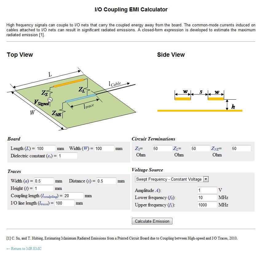
6 History Begin development of numerical modeling software for EMC analysis at UMR Investigation of fundamental EMI source mechanisms driving common-mode radiation from printed circuit boards with attached cables, IEEE Trans. on EMC, Nov ~40 publications relating to ability of various PCB structures to radiate First Maximum Radiated Emission Calculator (MREMC) Calculating radiated emissions due to I/O line coupling on printed circuit boards using the imbalance difference method, IEEE Trans. on EMC, Feb Development of algorithms for calculating radiated emissions and EM coupling for various PCB structures Formation of EMC Expert System Consortium Estimating maximum radiated emissions from printed circuit boards with an attached cable, IEEE Trans. on EMC, Feb Development of Performance- Based Design for EMC Process 6
7 Maximum Radiated Emissions Concept 315 MHz RF Transmitter (5 watts) Connector for Antenna What is the maximum 3-meter radiated field strength at 315 MHz? a. impossible to predict without knowing what antenna is connected b. impossible to predict even if the antenna is known c. 15 V/m d. none of the above 7
8 Maximum Radiated Emissions Concept 315 MHz RF Transmitter (5 watts) Connector for Antenna What is the maximum 3-meter radiated field strength at 315 MHz? P rec 2 = Prad 1 E D = ηp 2 0 E rad max = D 2 0 4πr 2 η 2π r 8
9 Maximum Radiated Emissions Concept 315 MHz RF Transmitter (5 watts) Connector for Antenna What is the maximum 3-meter radiated field strength at 315 MHz? E max ηp rad ( 377Ω)( 5W) = D 2 0 = (. ) =. V/m 2πr 2π( 3m) 9

10 Maximum Radiated Emissions Concept What is the maximum 3-meter radiated field strength at 200 MHz? We can put an upper bound on the radiated emissions at any given frequency! The more we know about the product design, the lower this upper bound becomes. 10


11 Maximum Radiated Emissions Concept Possible Antenna? Possible Source? (Processor with 200-MHz clock) 11

12 Maximum Radiated Emissions Calculation Heatsink ~ VDM Noise voltage V CM ~ V CM = C C heatsink board V DM Cable To Floor V DM Equivalent voltage C r C F F board = heatsink board cable E max To Floor References [1] H. Shim and T. Hubing, Model for Estimating Radiated Emissions from a Printed Circuit Board with Attached Cables Driven by Voltage-Driven Sources, IEEE Transactions on Electromagnetic Compatibility, vol. 47, no. 4, Nov. 2005, pp [2] Shaowei Deng, Todd Hubing, and Daryl Beetner, "Estimating Maximum Radiated Emissions From Printed Circuit Boards With an Attached Cable, IEEE Trans. on Electromagnetic Compatibility, vol. 50, no. 1, Feb. 2008, pp


13 Maximum Radiated Emissions Calculation 5cm 5cm 20cm 20cm 1cm Spacing between heatsink and board is 1 cm 100 cm C heatsink C board = 0.43 pf = 5.14 pf 13

14 Maximum Radiated Emissions Calculator 14
15 Performance-Based EMC Design Procedure Step I: For each net on each board: 1. Determine worst-case signal characteristics 2. Calculate maximum possible emissions from signal driving matched antenna 3. If > limit at any frequency, control risetime with series resistor 4. Recalculate maximum possible emissions from signal driving matched antenna 5. Proceed to Step II. 15
16 MS Excel Spreadsheet Calculation 16
17 Design Review Procedure Step II: For each net at each frequency over the limit: 1. Determine worst-case emissions due to each of the 5 MREMC algorithms that apply to your design 2. For any net that does not meet the specification at every frequency as determined by a given algorithm, adjust the design until the net is compliant. 17
18 Example 1: Microcontroller Output Driver Automotive microcontroller in typical application: Suppose we connected an output of this microcontroller directly up to an impedance-matched antenna Available Information V source = 3.3 V I max = 20 ma C in = 5 pf R series = 0 Ω CLK Freq = 100 khz Calculated Parameters R source = 165 Ω T = 10 µs t r = 1.82 ns 3-METER E-FIELD IN DB(uV/M) Absolute maximum possible emissions! FREQUENCY IN MHZ Maximum Radiated Field FCC Limit 18
 100.0 90.0 80.")
19 Example 1: Microcontroller Output Driver Same output with 20-kΩ series resistor: Suppose we connected an output of this microcontroller directly up to an impedance-matched antenna Available Information V source = 3.3 V I max = 20 ma C in = 5 pf R series = 20 kω CLK Freq = 100 khz Calculated Parameters R source = 8165 Ω T = 10 µs t r = ns 3-METER E-FIELD IN DB(uV/M) FREQUENCY IN MHZ Maximum Radiated Field FCC Limit 19
20 Series Resistors Why use series resistors to control transition times? Optimal control Minimal cost / Minimal footprint Predictable behavior Easy to adjust without affecting layout Reduces power bus noise 20
21 Example 2: Microcontroller Output Driver Same output with 1 MHz output: Suppose we connected an output of this microcontroller directly up to an impedance-matched antenna Available Information V source = 3.3 V I max = 20 ma C in = 5 pf R series = 0 kω CLK Freq = 1 MHz Calculated Parameters R source = 165 Ω T = 1 µs t r = 1.82 ns 3-METER E-FIELD IN DB(uV/M) Maximum Radiated Field 80.0 FCC Limit FREQUENCY IN MHZ 21
22 Example 2: Microcontroller Output Driver Same output with 1 MHz output and 8-kΩ series resistor: Suppose we connected an output of this microcontroller directly up to an impedance-matched antenna Available Information V source = 3.3 V 90.0 Maximum Radiated Field I max = 20 ma C in = 5 pf R series = 8 kω CLK Freq = 1 MHz Calculated Parameters R source = 8165 Ω T = 1 µs t r = 90 ns 3-METER E-FIELD IN DB(uV/M) 80.0 FCC Limit FREQUENCY IN MHZ 22
23 Example 3: Xilinx Vertex-6 FPGA SelectIO TM With 1 MHz output : Suppose we connected an output of this FPGA directly up to an impedance-matched antenna Available Information V source = 2.5 V I max = 240 ma * C in = 5 pf R series = 0 kω CLK Freq = 1 MHz Calculated Parameters R source = 50 Ω T = 1 µs t r = 0.55 ns 23
24 Example 3: Xilinx Vertex-6 FPGA SelectIO TM With 1 MHz output and 20-kΩ series resistor: Suppose we connected an output of this FPGA directly up to an impedance-matched antenna Available Information V source = 2.5 V I max = 240 ma * C in = 5 pf R series = 20 kω CLK Freq = 1 MHz Calculated Parameters R source = 50 Ω T = 1 µs t r = 221 ns 24
25 Example 4: Xilinx Vertex-6 FPGA SelectIO TM With 32 MHz output and 0-Ω series resistor: Suppose we connected an output of this FPGA directly up to an impedance-matched antenna Available Information V source = 2.5 V I max = 240 ma * C in = 5 pf R series = 0 kω CLK Freq = 32 MHz Calculated Parameters R source = 50 Ω T = 31 ns t r = 0.55 ns 25
26 Example 4: Xilinx Vertex-6 FPGA SelectIO TM With 32 MHz output and 500-Ω series resistor : Suppose we connected an output of this FPGA directly up to an impedance-matched antenna Available Information V source = 2.5 V I max = 240 ma * C in = 5 pf R series = 500 Ω CLK Freq = 32 MHz Calculated Parameters R source = 50 Ω T = 31 ns t r = 6.0 ns 26


27 3 Elements of a Radiated Emissions Problem SOURCE ANTENNA 27
28 MREMC Algorithms (Nets) Direct Radiation from Trace Need to know: net dimensions Trace Drives an Attached Cable and/or Heatsink Need to know: net dimensions, net placement, connector placement, and board dimensions Trace Couples to another Trace that Drives an Attached Cable Need to know: net dimensions, net placement, connector placement, and board dimensions Trace Drives the Power Bus Need to know: board dimensions 28

29 MREMC Algorithms (Nets) Direct Radiation from 10-cm trace, 1-mm above plane 29

30 MREMC Algorithms (Nets) Trace Couples to another Trace that Drives an Attached Cable 30
31 MREMC Algorithms (Nets) Trace Drives an Attached Cable and/or Heatsink 31

32 MREMC Algorithms (Nets) Trace Drives an Attached Cable and/or Heatsink 32
33 MREMC Algorithms (Components) Direct Radiation from Component Negligible Component Drives an Attached Cable and/or Heatsink Measure or model the equivalent dipole source for the component and use the trace algorithm Component Couples to another Trace that Drives an Attached Cable Measure or model the equivalent dipole source for the component and use the trace algorithm Component Drives the Power Bus Need to know: board dimensions, CPD and load Cs, component datasheet information 33
34 MREMC Algorithms (Shielded Products) Board analysis should be done as if there were no shield E-field coupling problems can be mitigated with E-field shielding Common-mode currents on cables can be mitigated enclosure to cable filtering Chassis connection to chassis ground Wiring Harness Chassis connection to chassis ground Capacitors connecting chassis ground to the digital return plane Chassis Ground Plane Digital Return Plane 34


35 MREMC Algorithms (Differential Signals) h = no plane h = small - w/ plane Use Imbalance Difference Model to convert all differential signals to equivalent common-mode sources Then apply the same algorithms used for singleended signals 35


36 Susceptibility Calculations PORT 1 PORT 2 Maximum Radiated Emissions Calculator (MREMC) Calculate Maximum Possible S21 36

37 Application to Infotainment System 5 Circuit Boards, mixed-signal RF, audio, video Internal ribbon cable connections Unshielded external connections AM/FM Radio 3 Camera Interfaces GPS DVD Player USB Fold-out Display 37


38 EMC Testing 38

39 Identify Antennas 39


40 Design Guidelines Many design rules were violated in the final design. Attempting to comply with a complete list of design rules would have made the product unnecessarily expensive. Nevertheless, some rules make too much sense to ignore. (Even if they are not explicitly required.) e.g. No ground traces. No shared ground vias. 40

41 Design Flexibility It s a good idea to leave options open to deal with unexpected issues. e.g. grounding option 41

42 Design Standards Many circuit geometries were based on known success with prior products. e.g. GPS antenna interface 42
43 For This Product Design (Nets) Direct Radiation from Trace No calculations made. Provided HF current return for all nets not eliminated after Step 1 (critical nets). Trace Drives an Attached Cable and/or Heatsink Optimized each critical net, but relied on filtering to chassis to guarantee compliance. Trace Couples to another Trace that Drives an Attached Cable No calculations made. Visually highlighted all I/O and kept several trace heights away from critical nets. Trace Drives the Power Bus No calculations made. Focused on providing excellent HF decoupling. 43
44 For This Product Design (Components) Direct Radiation from Component No calculations made. Negligible. Component Drives an Attached Cable and/or Heatsink No calculations made. Judged to be a non-issue. Component Couples to another Trace that Drives an Attached Cable No calculations made. Visually highlighted all I/O and kept critical components away. Component Drives the Power Bus No calculations made. Focused on providing excellent HF decoupling. 44
45 Current Project Status Documenting MREMC algorithms Increasing awareness Looking for software partner Formulating radiated susceptibility algorithms 45


46 Performance-Based EMC Design of Electronic Systems In Compliance Magazine, May Automotive Testing Technology International, Nov
47 Expected Outcomes Software tools will make this technique easier to implement and accessible to non-expert design engineers Will increase consumer demand for EMC-specific component information Will not replace EMC engineers, but will allow more sophisticated designs Will help engineers to use numerical EM modeling tools more effectively 47
Device Detection and Monitoring of Unintentional Radiated Emissions
 Clemson Vehicular Electronics Laboratory Automotive EMC Workshop Capable and Reliable Electronic Systems Design October 5, 212 Device Detection and Monitoring of Unintentional Radiated Emissions Todd Hubing
Todd H. Hubing Michelin Professor of Vehicular Electronics Clemson University
 Essential New Tools for EMC Diagnostics and Testing Todd H. Hubing Michelin Professor of Vehicular Electronics Clemson University Where is Clemson University? Clemson, South Carolina, USA Santa Clara Valley
Solutions for EMC Issues in Automotive System Transmission Lines
 Solutions for EMC Issues in Automotive System Transmission Lines Todd H. Hubing Michelin Professor of Vehicle Electronics Clemson University A P R. 1 0. 2 0 1 4 TM External Use EMC Requirements and Key
Solutions for EMC Issues in Automotive System Transmission Lines
 June 23, 2010 Solutions for EMC Issues in Automotive System Transmission Lines FTF-ENT-F0174 Todd Hubing Clemson University and VortiQa are trademarks of Freescale Semiconductor, Inc. All other product
TECHNICAL REPORT: CVEL Maximum Radiated Emission Calculator: Common-mode EMI Algorithm. Chentian Zhu and Dr. Todd Hubing. Clemson University
 TECHNICAL REPORT: CVEL-13-051 Maximum Radiated Emission Calculator: Common-mode EMI Algorithm Chentian Zhu and Dr. Todd Hubing Clemson University December 23, 2013 Table of Contents Abstract... 3 1. Introduction...
Chapter 12 Digital Circuit Radiation. Electromagnetic Compatibility Engineering. by Henry W. Ott
 Chapter 12 Digital Circuit Radiation Electromagnetic Compatibility Engineering by Henry W. Ott Forward Emission control should be treated as a design problem from the start, it should receive the necessary
Todd Hubing. Clemson University. Cabin Environment Communication System. Controls Airbag Entertainment Systems Deployment
 Automotive Component Measurements for Determining Vehicle-Level Radiated Emissions Todd Hubing Michelin Professor of Vehicular Electronics Clemson University Automobiles are Complex Electronic Systems
BIRD 74 - recap. April 7, Minor revisions Jan. 22, 2009
 BIRD 74 - recap April 7, 2003 Minor revisions Jan. 22, 2009 Please direct comments, questions to the author listed below: Guy de Burgh, EM Integrity mail to: gdeburgh@nc.rr.com (919) 457-6050 Copyright
EMC Simulation of Consumer Electronic Devices
 of Consumer Electronic Devices By Andreas Barchanski Describing a workflow for the EMC simulation of a wireless router, using techniques that can be applied to a wide range of consumer electronic devices.
EMI. Chris Herrick. Applications Engineer
 Fundamentals of EMI Chris Herrick Ansoft Applications Engineer Three Basic Elements of EMC Conduction Coupling process EMI source Emission Space & Field Conductive Capacitive Inductive Radiative Low, Middle
Understanding and Optimizing Electromagnetic Compatibility in Switchmode Power Supplies
 Understanding and Optimizing Electromagnetic Compatibility in Switchmode Power Supplies 1 Definitions EMI = Electro Magnetic Interference EMC = Electro Magnetic Compatibility (No EMI) Three Components
Verifying Simulation Results with Measurements. Scott Piper General Motors
 Verifying Simulation Results with Measurements Scott Piper General Motors EM Simulation Software Can be easy to justify the purchase of software packages even costing tens of thousands of dollars Upper
Frequently Asked EMC Questions (and Answers)
") Frequently Asked EMC Questions (and Answers) Elya B. Joffe President Elect IEEE EMC Society e-mail: eb.joffe@ieee.org December 2, 2006 1 I think I know what the problem is 2 Top 10 EMC Questions 10, 9
Frequently Asked EMC Questions (and Answers) Elya B. Joffe President Elect IEEE EMC Society e-mail: eb.joffe@ieee.org December 2, 2006 1 I think I know what the problem is 2 Top 10 EMC Questions 10, 9
AN IMPROVED MODEL FOR ESTIMATING RADIATED EMISSIONS FROM A PCB WITH ATTACHED CABLE
 Progress In Electromagnetics Research M, Vol. 33, 17 29, 2013 AN IMPROVED MODEL FOR ESTIMATING RADIATED EMISSIONS FROM A PCB WITH ATTACHED CABLE Jia-Haw Goh, Boon-Kuan Chung *, Eng-Hock Lim, and Sheng-Chyan
2620 Modular Measurement and Control System
 European Union (EU) Council Directive 89/336/EEC Electromagnetic Compatibility (EMC) Test Report 2620 Modular Measurement and Control System Sensoray March 31, 2006 April 4, 2006 Tests Conducted by: ElectroMagnetic
COMPUTER modeling software based on electromagnetic
 68 IEEE TRANSACTIONS ON ELECTROMAGNETIC COMPATIBILITY, VOL. 49, NO. 1, FEBRUARY 2007 Analysis of Radiated Emissions From a Printed Circuit Board Using Expert System Algorithms Yan Fu and Todd Hubing, Fellow,
THE TWIN standards SAE J1752/3 [1] and IEC 61967
![THE TWIN standards SAE J1752/3 [1] and IEC 61967](/thumbs/89/97779445.jpg "THE TWIN standards SAE J1752/3 [1] and IEC 61967") IEEE TRANSACTIONS ON ELECTROMAGNETIC COMPATIBILITY, VOL. 49, NO. 4, NOVEMBER 2007 785 Characterizing the Electric Field Coupling from IC Heatsink Structures to External Cables Using TEM Cell Measurements
IEEE TRANSACTIONS ON ELECTROMAGNETIC COMPATIBILITY, VOL. 49, NO. 4, NOVEMBER 2007 785 Characterizing the Electric Field Coupling from IC Heatsink Structures to External Cables Using TEM Cell Measurements
10 Safety earthing/grounding does not help EMC at RF
 1of 6 series Webinar #3 of 3, August 28, 2013 Grounding, Immunity, Overviews of Emissions and Immunity, and Crosstalk Contents of Webinar #3 Topics 1 through 9 were covered by the previous two webinars
EMC review for Belle II (Grounding & shielding plans) PXD DEPFET system
 PXD DEPFET system") EMC review for Belle II (Grounding & shielding plans) PXD DEPFET system Outline 1. Introduction 2. Grounding strategy Implementation aspects 3. Noise emission issues Test plans 4. Noise immunity issues
EMC review for Belle II (Grounding & shielding plans) PXD DEPFET system Outline 1. Introduction 2. Grounding strategy Implementation aspects 3. Noise emission issues Test plans 4. Noise immunity issues
Guidance and Declaration - Electromagnetic Compatibility (EMC) for the Delfi PTS ii Portable Tourniquet System
 for the Delfi PTS ii Portable Tourniquet System") Guidance and Declaration - Electromagnetic Compatibility (EMC) for the Delfi TS ii ortable Tourniquet System Guidance and manufacturer s declaration electromagnetic emissions The TS ii ortable Tourniquet
Guidance and Declaration - Electromagnetic Compatibility (EMC) for the Delfi TS ii ortable Tourniquet System Guidance and manufacturer s declaration electromagnetic emissions The TS ii ortable Tourniquet
EMC cases study. Antonio Ciccomancini Scogna, CST of America CST COMPUTER SIMULATION TECHNOLOGY
 EMC cases study Antonio Ciccomancini Scogna, CST of America antonio.ciccomancini@cst.com Introduction Legal Compliance with EMC Standards without compliance products can not be released to the market Failure
TECHNICAL REPORT: CVEL Investigation of the Imbalance Difference Model and its Application to Various Circuit Board and Cable Geometries
 TECHNICAL REPORT: CVEL-0-07.0 Investigation of the Imbalance Difference Model and its Application to Various Circuit Board and Cable Geometries Hocheol Kwak and Dr. Todd Hubing Clemson University May.
X2Y versus CM Chokes and PI Filters. Content X2Y Attenuators, LLC
 X2Y versus CM Chokes and PI Filters 1 Common Mode and EMI Most EMI compliance problems are common mode emissions. Only 10 s of uas in external cables are enough to violate EMC standards. 2 Common Mode
CHAPTER 6 EMI EMC MEASUREMENTS AND STANDARDS FOR TRACKED VEHICLES (MIL APPLICATION)
") 147 CHAPTER 6 EMI EMC MEASUREMENTS AND STANDARDS FOR TRACKED VEHICLES (MIL APPLICATION) 6.1 INTRODUCTION The electrical and electronic devices, circuits and systems are capable of emitting the electromagnetic
147 CHAPTER 6 EMI EMC MEASUREMENTS AND STANDARDS FOR TRACKED VEHICLES (MIL APPLICATION) 6.1 INTRODUCTION The electrical and electronic devices, circuits and systems are capable of emitting the electromagnetic
Understanding the Unintended Antenna Behavior of a Product
 Understanding the Unintended Antenna Behavior of a Product Colin E. Brench Southwest Research Institute Electromagnetic Compatibility Research and Testing colin.brench@swri.org Radiating System Source
Todd Hubing. Clemson Vehicular Electronics Laboratory Clemson University
 Todd Hubing Clemson Vehicular Electronics Laboratory Clemson University FCC Emissions Test Radiation from a shielded commercial product with attached cables May 28 2 Typical Field Strengths FCC Class A
Electromagnetic Compatibility ( EMC )
") Electromagnetic Compatibility ( EMC ) Introduction EMC Testing 1-2 -1 Agenda System Radiated Interference Test System Conducted Interference Test 1-2 -2 System Radiated Interference Test Open-Area Test
Electromagnetic Compatibility ( EMC ) Introduction EMC Testing 1-2 -1 Agenda System Radiated Interference Test System Conducted Interference Test 1-2 -2 System Radiated Interference Test Open-Area Test
TECHNICAL REPORT: CVEL Special Considerations for PCB Heatsink Radiation Estimation. Xinbo He and Dr. Todd Hubing Clemson University
 TECHNICAL REPORT: CVEL-11-27 Special Considerations for PCB Heatsink Radiation Estimation Xinbo He and Dr. Todd Hubing Clemson University May 4, 211 Table of Contents Abstract... 3 1. Configuration for
TECHNICAL REPORT: CVEL
 TECHNICAL REPORT: CVEL-13-041 Preliminary Investigation of the Current Path and Circuit Parameters Associated with the Characteristic Ringing in a MOSFET Power Inverter J. Hunter Hayes and Dr. Todd Hubing
ROD ANTENNA TESTING Complete article download from: EMI TESTING. Basic RE102 test (2-30 MHz)
") ROD ANTENNA TESTING Complete article download from: http://stevejensenconsultants.com/rod_ant.pdf EMI TESTING Steve Jensen Steve Jensen Consultants Inc. Sept. 26, 2005 Applicable for DO-160 sec. 21 and
ROD ANTENNA TESTING Complete article download from: http://stevejensenconsultants.com/rod_ant.pdf EMI TESTING Steve Jensen Steve Jensen Consultants Inc. Sept. 26, 2005 Applicable for DO-160 sec. 21 and
EUA2011A. Low EMI, Ultra-Low Distortion, 2.5-W Mono Filterless Class-D Audio Power Amplifier DESCRIPTION FEATURES APPLICATIONS
 Low EMI, Ultra-Low Distortion, 2.5-W Mono Filterless Class-D Audio Power Amplifier DESCRIPTION The EUA2011A is a high efficiency, 2.5W mono class-d audio power amplifier. A new developed filterless PWM
A Comparison Between MIL-STD and Commercial EMC Requirements Part 2. By Vincent W. Greb President, EMC Integrity, Inc.
 A Comparison Between MIL-STD and Commercial EMC Requirements Part 2 By Vincent W. Greb President, EMC Integrity, Inc. OVERVIEW Compare and contrast military (i.e., MIL-STD) and commercial EMC immunity
Characterization of Integrated Circuits Electromagnetic Emission with IEC
 Characterization of Integrated Circuits Electromagnetic Emission with IEC 61967-4 Bernd Deutschmann austriamicrosystems AG A-8141 Unterpremstätten, Austria bernd.deutschmann@ieee.org Gunter Winkler University
Electromagnetic Compatibility
 Electromagnetic Compatibility Introduction to EMC International Standards Measurement Setups Emissions Applications for Switch-Mode Power Supplies Filters 1 What is EMC? A system is electromagnetic compatible
A NEW COMMON-MODE VOLTAGE PROBE FOR PREDICTING EMI FROM UNSHIELDED DIFFERENTIAL-PAIR CABLES
 A NEW COMMON-MODE VOLTAGE PROBE FOR PREDICTING EMI FROM UNSHIELDED DIFFERENTIAL-PAIR CABLES Neven Pischl Bay Networks Division of Nortel Networks Santa Clara, CA npischl@nortelnetworks.com (408) 495 3261
FlexRay Communications System. Physical Layer Common mode Choke EMC Evaluation Specification. Version 2.1
 FlexRay Communications System Physical Layer Common mode Choke EMC Evaluation Specification Version 2.1 Disclaimer DISCLAIMER This specification as released by the FlexRay Consortium is intended for the
TECHNICAL REPORT: CVEL EMI Source Modeling of the John Deere CA6 Motor Driver. C. Zhu, A. McDowell and T. Hubing Clemson University
 TECHNICAL REPORT: CVEL-11-029 EMI Source Modeling of the John Deere CA6 Motor Driver C. Zhu, A. McDowell and T. Hubing Clemson University October 1, 2011 Table of Contents Executive Summary... 3 1. Introduction...
Testing for EMC Compliance: Approaches and Techniques October 12, 2006
 : Approaches and Techniques October 12, 2006 Ed Nakauchi EMI/EMC/ESD/EMP Consultant Emulex Corporation 1 Outline Discuss EMC Basics & Physics Fault Isolation Techniques Tools & Techniques Correlation Analyzer
From IC characterization to system simulation by systematic modeling bottom up approach
 From IC characterization to system simulation by systematic modeling bottom up approach Frédéric Lafon, François de Daran VALEO VIC, Rue Fernand Pouillon, 944 Creteil Cedex, France, frederic.lafon@valeo.com
EMI AND BEL MAGNETIC ICM
 EMI AND BEL MAGNETIC ICM ABSTRACT Electromagnetic interference (EMI) in a local area network (LAN) system is a common problem that every LAN system designer faces, and it is a growing problem because the
Top Ten EMC Problems & EMC Troubleshooting Techniques by Kenneth Wyatt, DVD, Colorado Springs Rev. 1, Feb 26, 2007
 EMC Engineering Top Ten EMC Problems & EMC Troubleshooting Techniques by Kenneth Wyatt, DVD, Colorado Springs Rev. 1, Feb 26, 2007 1a. Ground Impedance The overwhelming majority of high-frequency problems,
Advanced Topics in EMC Design. Issue 1: The ground plane to split or not to split?
 NEEDS 2006 workshop Advanced Topics in EMC Design Tim Williams Elmac Services C o n s u l t a n c y a n d t r a i n i n g i n e l e c t r o m a g n e t i c c o m p a t i b i l i t y e-mail timw@elmac.co.uk
EMC analysis workflow
 EMC analysis workflow Antonio Ciccomancini Scogna, CST of America antonio.ciccomancini@cst.com EMC/EMI Applications Emissions Susceptibility E3 Typical Emissions Issues 1 2 Image courtesy of Johnson Controls
Using TEM Cell Measurements to Estimate the Maximum Radiation From PCBs With Cables Due to Magnetic Field Coupling
 IEEE TRANSACTIONS ON ELECTROMAGNETIC COMPATIBILITY, VOL. 50, NO. 2, MAY 2008 419 from TEM mode to higher order modes is not affected. Thus, the energy converted from TEM mode to higher order modes is still
Modeling and Simulation of Powertrains for Electric and Hybrid Vehicles
 Modeling and Simulation of Powertrains for Electric and Hybrid Vehicles Dr. Marco KLINGLER PSA Peugeot Citroën Vélizy-Villacoublay, FRANCE marco.klingler@mpsa.com FR-AM-5 Background The automotive context
Novel Modeling Strategy for a BCI set-up applied in an Automotive Application
 Novel Modeling Strategy for a BCI set-up applied in an Automotive Application An industrial way to use EM simulation tools to help Hardware and ASIC designers to improve their designs for immunity tests.
Chapter 16 PCB Layout and Stackup
 Chapter 16 PCB Layout and Stackup Electromagnetic Compatibility Engineering by Henry W. Ott Foreword The PCB represents the physical implementation of the schematic. The proper design and layout of a printed
Automated Near-Field Scanning to Identify Resonances
 Automated Near-Field Scanning to Identify Resonances Muchaidze, Giorgi (1), Huang Wei (2), Jin Min (1), Shao Peng (2), Jim Drewniak (2) and David Pommerenke (2) (1) Amber Precision Instruments Santa Clara,
EMC for Printed Circuit Boards
 9 Bracken View, Brocton Stafford, Staffs, UK tel: +44 (0)1785 660 247 fax +44 (0)1785 660 247 email: keith.armstrong@cherryclough.com web: www.cherryclough.com EMC for Printed Circuit Boards Basic and
PHY Layout APPLICATION REPORT: SLLA020. Ron Raybarman Burke S. Henehan 1394 Applications Group
 PHY Layout APPLICATION REPORT: SLLA020 Ron Raybarman Burke S. Henehan 1394 Applications Group Mixed Signal and Logic Products Bus Solutions November 1997 IMPORTANT NOTICE Texas Instruments (TI) reserves
ELECTROMAGNETIC COMPATIBILITY HANDBOOK 1. Chapter 8: Cable Modeling
 ELECTROMAGNETIC COMPATIBILITY HANDBOOK 1 Chapter 8: Cable Modeling Related to the topic in section 8.14, sometimes when an RF transmitter is connected to an unbalanced antenna fed against earth ground
Design for EMI & ESD compliance DESIGN FOR EMI & ESD COMPLIANCE
 DESIGN FOR EMI & ESD COMPLIANCE All of we know the causes & impacts of EMI & ESD on our boards & also on our final product. In this article, we will discuss some useful design procedures that can be followed
The Ground Myth IEEE. Bruce Archambeault, Ph.D. IBM Distinguished Engineer, IEEE Fellow 18 November 2008
 The Ground Myth Bruce Archambeault, Ph.D. IBM Distinguished Engineer, IEEE Fellow barch@us.ibm.com 18 November 2008 IEEE Introduction Electromagnetics can be scary Universities LOVE messy math EM is not
LS200 TEST DATA IEC61000 SERIES
 TEST DATA IEC61000 SERIES DWG. No. PA607-58-01 APPD CHK DWG TDK-Lambda INDEX LS200 PAGE 1. Electrostatic Discharge Immunity Test (IEC61000-4-2) R-1 2. Radiated Radio-Frequency Electromagnetic Field Immunity
Analogue circuit design for RF immunity
 Analogue circuit design for RF immunity By EurIng Keith Armstrong, C.Eng, FIET, SMIEEE, www.cherryclough.com First published in The EMC Journal, Issue 84, September 2009, pp 28-32, www.theemcjournal.com
AP7301 ELECTROMAGNETIC INTERFERENCE AND COMPATIBILITY L T P C COURSE OBJECTIVES:
 AP7301 ELECTROMAGNETIC INTERFERENCE AND COMPATIBILITY L T P C 3 0 0 3 COURSE OBJECTIVES: To understand the basics of EMI To study EMI Sources To understand EMI problems To understand Solution methods in
PCB Design Guidelines for Reduced EMI
 PCB Design Guidelines for Reduced EMI Guided By: Prof. Ruchi Gajjar Prepared By: Shukla Jay (13MECE17) Outline Power Distribution for Two-Layer Boards Gridding Power Traces on Two-Layer Boards Ferrite
IEEE RTPGE Automotive Datalinks over Twisted Quad Cabling
 Automotive Datalinks over Twisted Quad Cabling T. Müller, G. Armbrecht, S. Kunz Rosenberger Hochfrequenztechnik GmbH & Co. KG Outline Automotive Datalinks over Twisted Quad Cabling Twisted Quad fundamentals
Investigation of Cavity Resonances in an Automobile
 Investigation of Cavity Resonances in an Automobile Haixiao Weng, Daryl G. Beetner, Todd H. Hubing, and Xiaopeng Dong Electromagnetic Compatibility Laboratory University of Missouri-Rolla Rolla, MO 65409,
EMC Seminar Series All about EMC Testing and Measurement Seminar 1
 EMC Seminar Series All about EMC Testing and Measurement Seminar 1 Introduction to EMC Conducted Immunity Jeffrey Tsang Organized by : Department of Electronic Engineering 1 Basic Immunity Standards: IEC
MPC5606E: Design for Performance and Electromagnetic Compatibility
 Freescale Semiconductor, Inc. Document Number: AN5100 Application Note MPC5606E: Design for Performance and Electromagnetic Compatibility by: Tomas Kulig 1. Introduction This document provides information
PCI-EXPRESS CLOCK SOURCE. Features
 DATASHEET ICS557-01 Description The ICS557-01 is a clock chip designed for use in PCI-Express Cards as a clock source. It provides a pair of differential outputs at 100 MHz in a small 8-pin SOIC package.
Top Ten EMC Problems
 Top Ten EMC Problems presented by: Kenneth Wyatt Sr. EMC Consultant EMC & RF Design, Troubleshooting, Consulting & Training 10 Northern Boulevard, Suite 1 Amherst, New Hampshire 03031 +1 603 578 1842 www.silent-solutions.com
8-bit Microcontroller. Application Note. AVR040: EMC Design Considerations. Scope. Introduction
 AVR040: EMC Design Considerations Scope This application note covers the most common EMC problems designers encounter when using microcontrollers. It will briefly discuss the various phenomena. The reference
How EMxpert Diagnoses Board-Level EMC Design Issues
 Application Report EMxpert July 2011 - Cédric Caudron How EMxpert Diagnoses Board-Level EMC Design Issues ABSTRACT EMxpert provides board-level design teams with world-leading fast magnetic very-near-field
SN W Mono Filterless Class-D Audio Power Amplifier DESCRIPTION FEATURES APPLICATIONS. Typical Application Circuit
 2.6W Mono Filterless Class-D Audio Power Amplifier DESCRIPTION The SN200 is a 2.6W high efficiency filter-free class-d audio power amplifier in a.5 mm.5 mm wafer chip scale package (WCSP) that requires
LISN UP Application Note
 LISN UP Application Note What is the LISN UP? The LISN UP is a passive device that enables the EMC Engineer to easily distinguish between differential mode noise and common mode noise. This will enable
Heat sink. Insulator. µp Package. Heatsink is shown with parasitic coupling.
 X2Y Heatsink EMI Reduction Solution Summary Many OEM s have EMI problems caused by fast switching gates of IC devices. For end products sold to consumers, products must meet FCC Class B regulations for
TEST REPORT... 1 CONTENT...
 CONTENT TEST REPORT... 1 CONTENT... 2 1 TEST RESULTS SUMMARY... 3 2 EMC RESULTS CONCLUSION... 4 3 LABORATORY MEASUREMENTS... 6 4 EMI TEST... 7 4.1 CONTINUOUS CONDUCTED DISTURBANCE VOLTAGE TEST... 7 4.2
9 Specifications. Specifications NOMINAL CHARACTERISTICS
 9 Specifications Specifications NOMINAL CHARACTERISTICS WARRANTED CHARACTERISTICS Nominal characteristics describe parameters and attributes that are guaranteed by design, but do not have associated tolerances.
Appendix A: Specifications
 Established 1981 Advanced Test Equipment Rentals www.atecorp.com 800-404-ATEC (2832) Appendix A: Specifications This section provides a complete description of the video measurement set specifications.
DEPARTMENT FOR CONTINUING EDUCATION
 DEPARTMENT FOR CONTINUING EDUCATION Reduce EMI Emissions for FREE! by Bruce Archambeault, Ph.D. (reprinted with permission from Bruce Archambeault) Bruce Archambeault presents two courses during the University
An Investigation of the Effect of Chassis Connections on Radiated EMI from PCBs
 An Investigation of the Effect of Chassis Connections on Radiated EMI from PCBs N. Kobayashi and T. Harada Jisso and Production Technologies Research Laboratories NEC Corporation Sagamihara City, Japan
AFBR-59F2Z Data Sheet Description Features Applications Transmitter Receiver Package
 AFBR-59F2Z 2MBd Compact 6nm Transceiver for Data communication over Polymer Optical Fiber (POF) cables with a bare fiber locking system Data Sheet Description The Avago Technologies AFBR-59F2Z transceiver
MK1413 MPEG AUDIO CLOCK SOURCE. Features. Description. Block Diagram DATASHEET
 DATASHEET MK1413 Description The MK1413 is the ideal way to generate clocks for MPEG audio devices in computers. The device uses IDT s proprietary mixture of analog and digital Phase-Locked Loop (PLL)
Course Introduction. Content: 19 pages 3 questions. Learning Time: 30 minutes
 Course Introduction Purpose: This course discusses techniques that can be applied to reduce problems in embedded control systems caused by electromagnetic noise Objectives: Gain a basic knowledge about
IC Decoupling and EMI Suppression using X2Y Technology
 IC Decoupling and EMI Suppression using X2Y Technology Summary Decoupling and EMI suppression of ICs is a complex system level engineering problem complicated by the desire for faster switching gates,
OPEN TEM CELLS FOR EMC PRE-COMPLIANCE TESTING
 1 Introduction Radiated emission tests are typically carried out in anechoic chambers, using antennas to pick up the radiated signals. Due to bandwidth limitations, several antennas are required to cover
Model for Estimating Radiated Emissions from a Printed Circuit Board with Attached Cables Due to Voltage-Driven Sources
 Missouri University of Science and Technology Scholars' Mine Electrical and Computer Engineering Faculty Research & Creative Works Electrical and Computer Engineering 1-1-2005 Model for Estimating Radiated
Comparison of IC Conducted Emission Measurement Methods
 IEEE TRANSACTIONS ON INSTRUMENTATION AND MEASUREMENT, VOL. 52, NO. 3, JUNE 2003 839 Comparison of IC Conducted Emission Measurement Methods Franco Fiori, Member, IEEE, and Francesco Musolino, Member, IEEE
TECHNICAL REPORT: CVEL Parasitic Inductance Cancellation for Filtering to Chassis Ground Using Surface Mount Capacitors
 TECHNICAL REPORT: CVEL-14-059 Parasitic Inductance Cancellation for Filtering to Chassis Ground Using Surface Mount Capacitors Andrew J. McDowell and Dr. Todd H. Hubing Clemson University April 30, 2014
EUA W Mono Filterless Class-D Audio Power Amplifier DESCRIPTION FEATURES APPLICATIONS. Typical Application Circuit
 3-W Mono Filterless Class-D Audio Power Amplifier DESCRIPTION The EUA2011 is a high efficiency, 3W mono class-d audio power amplifier. A low noise, filterless PWM architecture eliminates the output filter,
ICS HDTV AUDIO/VIDEO CLOCK SOURCE. Features. Description. Block Diagram DATASHEET
 DATASHEET ICS662-03 Description The ICS662-03 provides synchronous clock generation for audio sampling clock rates derived from an HDTV stream. The device uses the latest PLL technology to provide superior
The Modeling & EM Simulation Assessment as Part of DFX Methodology
 International Journal of Electromagnetics and Applications: 2011; 1(1): 7-11 DOI: 10.5923/j.ijea.20110101.02 The Modeling & EM Simulation Assessment as Part of DFX Methodology B. Mihailescu 1,*, I. Plotog
Data Sheet. Description. Features. Transmitter. Applications. Receiver. Package
 AFBR-59F1Z 125MBd Compact 650 nm Transceiver for Data Communication over Polymer Optical Fiber (POF) cables with a bare fiber locking system Data Sheet Description The Avago Technologies AFBR-59F1Z transceiver
Electromagnetic Interference Mitigation
 Electromagnetic Interference Mitigation Picture or Drawing 20.7 x 8.6 cm Frits J.K. Buesink, Senior Researcher EMC frits.buesink@utwente.nl Funded by the European Union on the basis of Decision No 912/2009/EC,
Class-D Audio Power Amplifiers: PCB Layout For Audio Quality, EMC & Thermal Success (Home Entertainment Devices)
") Class-D Audio Power Amplifiers: PCB Layout For Audio Quality, EMC & Thermal Success (Home Entertainment Devices) Stephen Crump http://e2e.ti.com Audio Power Amplifier Applications Audio and Imaging Products
Class-D Audio Power Amplifiers: PCB Layout For Audio Quality, EMC & Thermal Success (Home Entertainment Devices) Stephen Crump http://e2e.ti.com Audio Power Amplifier Applications Audio and Imaging Products
Non-Ideal Behavior of Components
 Non-Ideal Behavior of Components Todd H. Hubing Dept. of Electrical and Computer Engineering Clemson, University Clemson, SC 29634 USA email: hubing@clemson.edu Telephone: 1-864-656-7219 Circuit Schematics
EMC TEST REPORT. for. Coliy Technology Co.,Ltd. Fluxgate Gaussmeter
 Page 1 of 48 EMC TEST REPORT for Coliy Technology Co.,Ltd. Fluxgate Gaussmeter Prepared for : Coliy Technology Co.,Ltd. Address : Block B,9 th Floor,Xinzhongtai Business Building,Gushu 2nd Road,Xi Town,Bao
Overview of EMC Regulations and Testing. Prof. Tzong-Lin Wu Department of Electrical Engineering National Taiwan University
 Overview of EMC Regulations and Testing Prof. Tzong-Lin Wu Department of Electrical Engineering National Taiwan University What is EMC Electro-Magnetic Compatibility ( 電磁相容 ) EMC EMI (Interference) Conducted
EMC problems from Common Mode Noise on High Speed Differential Signals
 EMC problems from Common Mode Noise on High Speed Differential Signals Bruce Archambeault, PhD Alma Jaze, Sam Connor, Jay Diepenbrock IBM barch@us.ibm.com 1 Differential Signals Commonly used for high
A Study of Conducted-Emission Stable Source Applied to the EMC US and EU Standards
 Fourth LACCEI International Latin American and Caribbean Conference for Engineering and Technology (LACCEI 2006) Breaking Frontiers and Barriers in Engineering: Education, Research and Practice, 21-23
We re In The Business Of Making Your Life Easier
 Systems RF Conducted Immunity System We re In The Business Of Making Your Life Easier AS00202 4 khz 200 MHz System AS03007 10 khz 3 GHz System RF Conducted Immunity Testing to IEC, Military & Automotive
1000BASE-T1 EMC Test Specification for Common Mode Chokes
 IEEE 1000BASE-T1 EMC Test Specification for Common Mode Chokes Version 1.0 Author & Company Dr. Bernd Körber, FTZ Zwickau Title 1000BASE-T1 EMC Test Specification for Common Mode Chokes Version 1.0 Date
Investigation of Electromagnetic Field Coupling from DC-DC Buck Converters to Automobile AM/FM Antennas
 CST North American Automotive Workshop Investigation of Electromagnetic Field Coupling from DC-DC Buck Converters to Automobile AM/FM Antennas Patrick DeRoy, CST of America, Framingham, Massachusetts,
150Hz to 1MHz magnetic field coupling to a typical shielded cable above a ground plane configuration
 150Hz to 1MHz magnetic field coupling to a typical shielded cable above a ground plane configuration D. A. Weston Lowfreqcablecoupling.doc 7-9-2005 The data and information contained within this report
Analysis of a PCB-Chassis System Including Different Sizes of Multiple Planes Based on SPICE
 Analysis of a PCB-Chassis System Including Different Sizes of Multiple Planes Based on SPICE Naoki Kobayashi (1), Todd Hubing (2) and Takashi Harada (1) (1) NEC, System Jisso Research Laboratories, Kanagawa,
11 Myths of EMI/EMC ORBEL.COM. Exploring common misconceptions and clarifying them. MYTH #1: EMI/EMC is black magic.
 11 Myths of EMI/EMC Exploring common misconceptions and clarifying them By Ed Nakauchi, Technical Consultant, Orbel Corporation What is a myth? A myth is defined as a popular belief or tradition that has
SIMULATION of EMC PERFORMANCE of GRID CONNECTED PV INVERTERS
 SIMULATION of EMC PERFORMANCE of GRID CONNECTED PV INVERTERS Qin Jiang School of Communications & Informatics Victoria University P.O. Box 14428, Melbourne City MC 8001 Australia Email: jq@sci.vu.edu.au
Connecting a Neuron 5000 Processor to an External Transceiver
 @ Connecting a Neuron 5000 Processor to an External Transceiver March 00 LonWorks Engineering Bulletin The Echelon Neuron 5000 Processor provides a media-independent communications port that can be configured