Solutions for EMC Issues in Automotive System Transmission Lines
|
|
|
- Derick Norman
- 6 years ago
- Views:
Transcription

1 Solutions for EMC Issues in Automotive System Transmission Lines Todd H. Hubing Michelin Professor of Vehicle Electronics Clemson University A P R TM External Use


2 EMC Requirements and Key Design Considerations Radiated Emissions Radiated Susceptibility Transient Immunity Electrostatic Discharge Bulk Current Injection 1 HF GND Risetime Control Filtered I/O Adequate Decoupling Balance Control 1 HF GND Filtered I/O Adequate Decoupling Balance Control LF Current Path Control Chassis GND on board Filtered I/O Adequate Decoupling LF Current Path Control Chassis GND on board Filtered I/O Adequate Decoupling 1 HF GND Chassis GND on board Filtered I/O Adequate Decoupling Balance Control Designing a product that is guaranteed to meet all of these requirements is relatively easy. Fixing a non-compliant product can be difficult and costly. External Use 1


3 Automotive EMI Sources, Victims and Antennas External Use 2
4 Agenda 10 rules for ensuring you meet your automotive EMC requirements the first time your product is tested. Hour 1 Hour 2 Hour 3 Hour 4 1. Control your transition times 2. Recognize where currents flow 3. Recognize the 4 (not 2) possible coupling mechanisms 4. Identify your antennas 5. Identify your sources 6. Don t rely on EMC design guidelines 7. Don t gap your ground planes 8. There are no shielded enclosures in the automotive world 9. Provide adequate power bus decoupling 10. Provide adequate transient protection External Use 3
5 First Rule of Automotive EMC Design To guarantee that your design will meet its EMC requirements the first time, you MUST: External Use 4

, the electrical behavior of the model is the same")
6 RLCG Parameters If the length of each section of the RLCG lumped model is small relative to a wavelength (e.g. n <<l/8), the electrical behavior of the model is the same as the electrical behavior of the transmission line. External Use 5
 Capacitance per unit length (F/m) This term is independent of the geometry External Use")
7 Propagation Velocity Determined by the dielectric material Propagation velocity (m/sec) v 1 1 LC Inductance per unit length (H/m) Capacitance per unit length (F/m) This term is independent of the geometry External Use 6
8 Propagation Delay (Electrical Length) RS S1 l Z0 RL t PD v Propagation Delay (sec) The propagation delay is the amount of time required for a signal to propagate from one point to another point (total distance, ) on the transmission line. External Use 7
 Low-Loss Approximation The")

9 Characteristic Impedance RS S1 l Z0 RL Z 0 R jl L G jc C Characteristic Impedance (ohms) Low-Loss Approximation The characteristic impedance is the ratio of the voltage to the current in a signal traveling in one direction down the transmission line. External Use 8
10 Attenuation RS S1 l Z0 RL V V e 0 x x=0 x=1m R jl G jc j x0 m Ve 0 Attenuation in db/m 20log x1m Ve 0 20 log e 8.7 R 2Z 0 Low-Loss Approximation Attenuation in db/m LC 4.34R Z 0 External Use 9
11 Dispersion RS S1 l Z0 RL x=0 x=1m R 2Z 0 Low-Loss Approximation Attenuation in db/m LC 4.34R Z 0 Notice that attenuation is a function of R, but at high frequencies, R is a function of frequency due to the skin effect. Therefore higher frequencies are attenuated more than lower frequencies. This can change the shape of the signal in the time domain, and this effect is called dispersion. External Use 10
12 When is a cable a transmission line? RS l VS Z0 RL at midpoint in transmission line at midpoint in transmission line Technically, always! But it will be most important to us when the propagation delay is greater than the transition time. External Use 11

13 When must a cable be modeled as a transmission line? RS l VS Z0 RL The answer depends on the application, but generally the following guidelines apply. For digital signals: When t r < 2 * t pd For RF signals: When > l/8 External Use 12
14 An Important Point RS l VS Z0 RL In most applications, anything that must be modeled as a transmission line must have a matched termination. This is usually undesirable from a cost and EMC perspective. Therefore, every effort should usually be taken to ensure that the signal bandwidth is no higher (or transition times are no shorter) than necessary. External Use 13

15 When cables are electrically short They can be modeled using their lumped RLCG parameters. RS l<<λ/8 VS Z0 RL RS VS RL Often, one or none of these parameters is significant relative to the source and load impedances External Use 14
16 When cables are electrically short Be careful not to model short cables or connectors with the full L or C unless you have shown the that other parameter can be neglected. Discontinuities with a characteristic impedance greater than the source and load impedances can be modeled with a lumped inductance. l L eq Z 01 Z 02 Z 01 Z 01 Z 01 Z 01 Z 01 Z 01 < Z 02 << 1 The value of this inductance is less than the value of the lumped parameter L in the RLCG model. Leq L 1 2 R 01 Z 02 External Use 15
17 When cables are electrically short Be careful not to model short cables or connectors with the full L or C unless you have shown the that other parameter can be neglected. Discontinuities with a characteristic impedance less than the source and load impedances can be modeled with a lumped capacitance. l Z 01 Z 02 Z 01 Z 01 Z 01 C eq Z 01 Z 01 Z 02 < Z 01 << 1 The value of this capacitance is less than the value of the lumped parameter C in the RLCG model. Ceq C 1 2 Z 02 R 01 External Use 16
18 When cables are not electrically short To eliminate reflections, transmission lines must have a controlled impedance and must be matched! RS l VS Z0 RL For signals with one source and one load, the match can occur at the source end: R S = Z 0. For signals with one source and more than one load, the match must generally occur at the load end: R L = Z 0. External Use 17
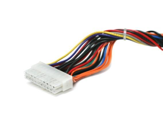
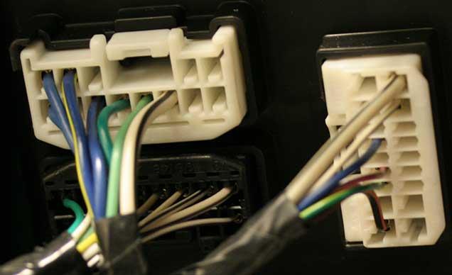
19 When is a wiring harness a transmission line? RS S1 l Z0 RL Steady state solution is always the wire-pair solution If we don t care about how we get to the steady state, then we don t need to worry about transmission line solutions. In most automotive applications, we don t care! External Use 18
20 When is a wiring harness a transmission line? RS S1 l Z0 RL If the risetime is much greater than the propagation delay, transmission line can be modeled as lumped element. length = 5 meters propagation delay ~ 30 nsec length = 50 cm propagation delay ~ 3 nsec External Use 19
21 When is a wiring harness a transmission line? 1. Every digital signal transition time should be forced to be >100 ns (unless this would prevent the circuit from working). 2. Signals that must transition faster than 100 ns, should transition in the longest permissible time. 3. Traces or cables that carry signals with transition times > 100 ns should not have matched terminations unless the length of the signal propagation is > 5 meters. 4. Traces or cables that carry signals with transition times > 10 ns should not have matched terminations unless the length of the signal propagation is > 50 cm. External Use 20
22 Control Transition Times CMOS Driver Model CMOS Input Model External Use 21
23 Control Transition Times t f t f Control transition times of digital signals! External Use 22
24 Control Transition Times Digital Signal Currents in CMOS Circuits t f t f Control transition times of digital signals! Can use a series resistor or ferrite when load is capacitive. Use appropriate logic for fast signals with matched loads. External Use 23
25 Control Transition Times Reducing risetime with a series resistor Reducing risetime with a parallel capacitor Good idea Bad idea External Use 24

26 3-METER E-FIELD IN DB(uV/M) Example 1: Microcontroller Output Driver Automotive microcontroller in typical application: Suppose we connected an output of this microcontroller directly up to an impedance-matched antenna Available Information V source = 3.3 V 90.0 Absolute maximum possible emissions! Maximum Radiated Field I max = 20 ma 80.0 FCC Limit C in = 5 pf R series = 0 W CLK Freq = 100 khz Calculated Parameters R source = 165 W T = 10 s t r = 1.82 ns FREQUENCY IN MHZ External Use 25
27 3-METER E-FIELD IN DB(uV/M) Example 1: Microcontroller Output Driver Same output with 20-kW series resistor: Suppose we connected an output of this microcontroller directly up to an impedance-matched antenna Available Information V source = 3.3 V I max = 20 ma Maximum Radiated Field FCC Limit C in = 5 pf 70.0 R series = 20 kw 60.0 CLK Freq = 100 khz 50.0 Calculated Parameters R source = 8165 W T = 10 s t r = ns FREQUENCY IN MHZ External Use 26
28 3-METER E-FIELD IN DB(uV/M) Example 2: Microcontroller Output Driver Same output with 1 MHz output: Suppose we connected an output of this microcontroller directly up to an impedance-matched antenna Available Information V source = 3.3 V I max = 20 ma C in = 5 pf Maximum Radiated Field FCC Limit R series = 0 kw CLK Freq = 1 MHz Calculated Parameters 40.0 R source = 165 W T = 1 s t r = 1.82 ns FREQUENCY IN MHZ External Use 27
29 3-METER E-FIELD IN DB(uV/M) Example 2: Microcontroller Output Driver Same output with 1 MHz output and 8-kW series resistor: Suppose we connected an output of this microcontroller directly up to an impedance-matched antenna Available Information V source = 3.3 V 90.0 Maximum Radiated Field I max = 20 ma 80.0 FCC Limit C in = 5 pf 70.0 R series = 8 kw 60.0 CLK Freq = 1 MHz 50.0 Calculated Parameters 40.0 R source = 8165 W T = 1 s t r = 90 ns FREQUENCY IN MHZ External Use 28


30 Amplitude TM Amplitude Amplitude RLC Circuits 10 Under-damped L R 2 C Time 10 Critically-damped 10 Over-damped L R 2 C 4 2 L R 2 C Time Time External Use 29
31 2nd Rule of Automotive EMC Design To guarantee that your design will meet its EMC requirements the first time, you MUST: External Use 30
32 Where does the return current flow? External Use 31
33 Where does the return current flow? External Use 32
34 Identify Current Paths Current takes the path of least impedance! > 100 khz this is generally the path of least inductance < 10 khz this is generally the path(s) of least resistance External Use 33
35 Identify Current Paths 6 VDC INPUT Where does the 56 MHz return current flow? +5 volts VOLTAGE REGULATOR ground +5 volts 56 MHZ OSC. +5 volts ground ground External Use 34
36 Identify Current Paths 6 VDC INPUT Where does the 6 VDC return current flow? +5 volts VOLTAGE REGULATOR ground +5 volts 56 MHZ OSC. +5 volts ground ground External Use 35
37 Identify Current Paths External Use 36
38 Identify Current Paths External Use 37
39 Identify Current Paths Where does the 10 khz return current flow? External Use 38
40 3rd Rule of Automotive EMC Design To guarantee that your design will meet its EMC requirements the first time, you MUST: External Use 39
41 Common Impedance Coupling I 1 R S1 R S2 + + V S1 V R R S2 RET I RET R L2 V RL2 L1 V RL1 I External Use 40
42 Conducted Coupling I 1 aka: Common Impedance Coupling R S1 R S2 + + V S1 V R R S2 RET I RET R L2 V RL2 L1 V RL1 I Requires 2 conductor connections between the source and victim. The only mechanism that couples DC level shifts. Most likely to be dominant at low frequencies, when source and victim share a current return path. Most likely to be dominant when sources are low impedance (high current) circuits. External Use 41
43 Conducted Coupling Examples Lights dim and radio dies when automobile engine is started. Power bus voltage spikes are heard as audible clicks on an AM radio using the same power source. An electrostatic discharge transient resets a microprocessor causing a system to shutdown. A lightning induced transient destroys the electronic components in a computer with a wired connection to the internet. External Use 42
44 Electric Field Coupling aka: Capacitive Coupling C 12 V S1 V S2 C 11 C 22 R L2 + + V R RL2 L1 V - RL1 - R S1 R S2 Requires 0 conductor connections between the source and victim. Coupling proportional to dv/dt. Most likely to be dominant at higher frequencies. Most likely to be dominant when sources are high impedance (high voltage) circuits. External Use 43
45 Electric Field Coupling Examples Coupling from circuit board heatsinks to cables or enclosures. AM radio interference from overhead power lines. Automotive component noise picked up by the rod antenna in CISPR 25 radiated emissions tests. Microprocessor resets due to indirect electrostatic discharges. External Use 44
 circuits.")
46 Magnetic Field Coupling aka: Inductive Coupling L 1 M 12 L 2 R S1 R S2 + + R L1 V S1 V S2 R L2 V RL2 V - RL1 - Requires 0 conductor connections between the source and victim. Coupling proportional to di/dt. Most likely to be dominant at higher frequencies. Most likely to be dominant when sources are low impedance (high current) circuits. External Use 45
47 Magnetic Field Coupling Examples Coupling from power transformers or fluorescent lighting ballasts. Jitter in CRT displays. 60 Hz hum in a handheld AM radio. Hard-drive corruption due to motor or transformer currents. External Use 46
48 4th Rule of Automotive EMC Design To guarantee that your design will meet its EMC requirements the first time, you MUST: External Use 47


49 When do wiring harnesses look like antennas? External Use 48
50 Identifying Antennas What makes an efficient antenna? l/2 Half-Wave Dipole Electrically Small Loop l/4 Quarter-Wave Monopole Size Two Halves External Use 49
51 Identifying Antennas Good Antenna Parts Poor Antenna Parts <100 MHz >100 MHz <100 MHz >100 MHz Cables Heatsinks Power planes Microstrip or stripline traces Microstrip or stripline traces Tall components Seams in shielding enclosures Anything that is not big Free-space wavelength at 100 MHz is 3 meters External Use 50
52 Identifying Antennas Common-Mode vs. Differential Mode z E max I c fz r s E max I d f 2 r sz I d fz s r l External Use 51


53 How are common-mode currents induced on cables? Voltage-Driven Mechanism Heatsink ~ VDM Noise voltage V CM ~ Cable Equivalent voltage V CM C C heat sin k board V DM V DM Cboard r C F F heat sin k board cable E max External Use 52

54 How are common-mode currents induced on cables? Current-Driven Mechanism Signal current loop induces a voltage between two good antenna parts. - Vcm + At 10 MHz and higher, milliamps of current flowing in a ground plane produces millivolts of voltage across the ground plane. A few millivolts driving a resonant antenna can result in radiated fields exceeding FCC limits. External Use 53

55 What do you think of this automotive BCM design? External Use 54

56 How are common-mode currents induced on cables? Direct-Coupling Mechanism Signals coupled to I/O lines can carry HF power off the board. External Use 55
57 How are common-mode currents induced on cables? DM-to-CM conversion due to cable and load imbalance RS S1 Z0 RL External Use 56
58 Common-mode and Differential-mode Current General Definition I h I hi DM I I I CM 1 2 I 1 = 3 Amps I 2 = 5 Amps I I hi 1 DM CM I2 I DM (1 h) I CM AND I DM V Z DM DM External Use 57

59 Driving a Ribbon Cable h = no plane h = small - w/ plane A perfect differential driver driving two adjacent wires in a ribbon cable produces no common-mode current on the ribbon cable. A single-ended driver driving two adjacent wires in a ribbon cable produces a exactly the same amount of common-mode current as a common-mode source with half the signal voltage Don t drive ribbon cable wires with single-ended sources unless you know the common-mode current will not be a problem. External Use 58
60 PCB Driving a Twisted Wire Pair h = 0.5 A perfect differential driver driving a perfect twisted-wire pair produces no common-mode current on the wire pair. A single-ended driver driving a twistedwire pair produces a exactly the same amount of common-mode current as a common-mode source with half the signal voltage Don t drive twisted-wire pairs with single-ended sources unless you know the common-mode current will not be a problem. External Use 59
61 5th Rule of Automotive EMC Design To guarantee that your design will meet its EMC requirements the first time, you MUST: External Use 60
62 Identify Sources Clocks Digital Data Analog signals Power supply switching Arcing Parasitic oscillations Narrow band, consistent Not as narrow as clocks, but clock frequency is usually identifiable. Bandwidth determined by signal source, consistent Appears broadband, but harmonics of switching frequency can be identified, consistent Broadband, intermittent Narrowband, possibly intermittent External Use 61
 For some ICs, the")


63 Identify Sources Active Devices (Power Pins) For some ICs, the high-frequency currents drawn from the power pins can be much greater than the high-frequency currents in the signals! External Use 62

64 Identify Sources Noise on the low-speed I/O For some ICs, significant high-frequency currents appear on low-speed I/O including outputs that never change state during normal operation! External Use 63
65 6th Rule of Automotive EMC Design To guarantee that your design will meet its EMC requirements the first time: External Use 64
66 EE371 Design Problem External Use 65


67 EMC Design Guideline Collection External Use 66
68 7th Rule of Automotive EMC Design To guarantee that your design will meet its EMC requirements the first time: External Use 67
69 Ground vs. Signal Return AGND Whenever I see more than one of these symbols on the schematic, I know there is [EMC] work for us here. T. Van Doren DGND External Use 68
70 Ground vs. Signal Return The purpose of a system ground is to provide a reference voltage and/or a safe path for fault currents. Signal currents flowing on a ground conductor can prevent a ground conductor from serving its intended purpose. Don t confuse ground conductors with signal return conductors. Rules for the routing of ground may conflict with the rules for routing signal or power returns. External Use 69
.")
71 Ground vs. Signal Return Circuit boards should have high-frequency ground! Why? Conductors referenced to different grounds can be good antennas. Signals referenced to two different grounds will be noisy (i.e. include the noise voltage between the two grounds). Layouts with more than one ground are more difficult, require more space and present more opportunities for critical mistakes. Excuses for employing more than one ground are generally based on inaccurate or out-dated information. External Use 70
72 Ground vs. Signal Return If grounds are divided, it is generally to control the flow of lowfrequency (<100 khz) currents. For example, Isolating battery negative (i.e. chassis ground) from digital ground Isolating digital ground from analog ground in audio circuits. This can be necessary at times to prevent common impedance coupling between circuits with low-frequency high-current signals and other sensitive electronic circuits. HOWEVER, it is still necessary to ensure that there is only 1 high-frequency ground. External Use 71
73 Ground vs. Signal Return Exercise: Trace the path of the digital and analog return currents. D/A PWM Driver Heatsink External Use 72
74 Ground vs. Signal Return Exercise: Trace the path of the digital and analog return currents. D/A PWM Driver Heatsink External Use 73
75 Ground vs. Signal Return Exercise: Trace the path of the digital and analog return currents. D/A PWM Driver Heatsink External Use 74
76 Lateral Isolation Chassis GND Rarely appropriate Analog GND Often the source of significant problems Digital GND External Use 75
77 Vertical Isolation Digital GND Analog GND Chassis GND Only one plane usually needs to be full size. One or zero vias should connect planes with different labels. External Use 76
78 Ground vs. Signal Return You don t need to gap a plane to control the flow of high frequency (> 1 MHz) currents. If you provide a low-inductance path for these currents to take, they will confine themselves to this path very well. External Use 77
79 Ground vs. Signal Return Rules for gapping a ground plane: 1. Don t do it! 2. If you must do it, never ever allow a trace or another plane to cross over the gap. 3. If you must do it, never ever place a gap between two connectors. 4. Remember that the conductors on either side of the gap are at different potentials. 5. See Rule #1! External Use 78
80 Provide a good HF chassis ground at connector Cables and enclosures are both good antenna parts. If they are not held to the same potential, they are likely to create a radiation problem. Exceptions: When there is no chassis ground When there are no connectors with cables Note: Sometimes low-frequency isolation between chassis and digital ground is necessary control the flow of low-frequency currents. However, even in these situations it is usually important to provide a good high-frequency connection. External Use 79
81 Question: When do you provide a chassis ground on the board? Answer: Whenever you have a metal enclosure OR a connection to vehicle chassis. Chassis connection to chassis ground Wiring Harness Chassis connection to chassis ground Capacitors connecting chassis ground to the digital return plane Chassis Ground Plane Digital Return Plane External Use 80

82 Chassis Ground Capacitors Caps with traces Better implementation External Use 81
83 Filtering Low-Pass Filters External Use 82
84 Filtering Design Exercise: Which low-pass filter is most appropriate in each case? External Use 83
85 Filtering Parasitics External Use 84
86 Filtering with 2 capacitors Two capacitors are more than twice as good as one. External Use 85

87 8th Rule of Automotive EMC Design To guarantee that your design will meet its EMC requirements the first time, you MUST recognize that: External Use 86
88 Shielding (a.) Electric Field Shielding (b.) + V - - V+ (c.) External Use 87
89 Shielding Magnetic Field Shielding (at low frequencies) External Use 88
90 Shielding Magnetic Field Shielding (at high frequencies) External Use 89
91 Shielding Enclosure Shielding External Use 90
92 9th Rule of Automotive EMC Design To guarantee that your design will meet its EMC requirements the first time, you MUST: External Use 91
93 The Concept of Power Bus Decoupling L P V board V inductance V inductance V supply L G Power Supply Printed Circuit Board External Use 92
94 The Concept of Power Bus Decoupling L P V board V supply L G Power Supply Printed Circuit Board External Use 93
95 The Concept of Power Bus Decoupling L trace L trace C d C d L d L d C b L trace L trace External Use 94
96 Effective Strategies for Choosing Amount of Decoupling Capacitance Required External Use 95
97 Rules for PCB Decoupling? Use small-valued capacitors for high-frequency decoupling. Locate capacitors near the power pins of active devices. Avoid capacitors with a low ESR! Run traces from device to capacitor, then to power planes. Location of decoupling capacitors is not relevant. Use the largest valued capacitors you can find in a given package size. Use 0.01 F for local decoupling! Use capacitors with a low ESR! Use F for local decoupling! Locate capacitors near the ground pins of active devices. Never put traces on decoupling capacitors. Local decoupling capacitors should have a range of values from 100 pf to 1 F! External Use 96
98 How much capacitance do you need? Impedance approach L trace L trace Z max ( f ) V = I NOISE MAX DEVICE MAX ( f ) ( f ) L trace C b L trace Z max 1 2 p f 1 C 2 p fl trace 1 = Z 2 p f C C 0 min max = 1 2 p f Z 0 = 1 ( 2 p f ) 0 max 2 L source f0 f 1 External Use 97
99 How much capacitance do you need? Capacitance Ratio approach Recognizing that CMOS loads are capacitances, we are simply using decoupling capacitors to charge load capacitances. R + V - C D C L Total decoupling capacitance is set to a value that is equal to the total device capacitance times the power bus voltage divided by the maximum power bus noise. External Use 98
100 How much capacitance do you need? Guidelines approach Let s do it the way that worked for somebody at sometime in the past. include one 0.01 uf local decoupling capacitor for each VCC pin of every active component on the board plus 1 bulk decoupling capacitor with a value equal to 5 times the sum of the local decoupling capacitance.. External Use 99

101 Effective Strategies for Locating Printed Circuit Board Decoupling Capacitors External Use 100
102 Boards with Closely Spaced Power Planes C b C d C d Power Distribution Model ~ (5-500 MHz) Board with power and ground planes External Use 101
103 Boards with Closely Spaced Power Planes C B = 3.4 nf L BULK = 5 nh L = 2nH D C BULK = 1 F C D = 10nF Bare Board Board with decoupling MHz 1 MHz 10 MHz 100 MHz 1 GHz External Use 102
104 For Boards with Closely-Spaced Planes The location of the decoupling capacitors is not critical. The value of the local decoupling capacitors is not critical, but it must be greater than the interplane capacitance. The inductance of the connection is the most important parameter of a local decoupling capacitor. None of the local decoupling capacitors are effective above a couple hundred megahertz. None of the local decoupling capacitors are supplying significant charge in the first few nanoseconds of a transition. External Use 103

105 External Use 104
106 Inductance of connections to planes On boards with closely spaced power and ground planes: Generally speaking, 100 decoupling capacitors connected through 1 nh of inductance will be as effective as 500 decoupling capacitors connected through 5 nh of inductance. 5 nh 0.5 nh External Use 105
107 Power Bus Decoupling Strategy With closely spaced (<.25 mm) planes size bulk decoupling to meet board requirements size high-frequency decoupling to meet board requirements mount local decoupling in most convenient locations don t put traces on capacitor pads too much capacitance is ok too much inductance is not ok References: T. H. Hubing, J. L. Drewniak, T. P. Van Doren, and D. Hockanson, Power Bus Decoupling on Multilayer Printed Circuit Boards, IEEE Transactions on Electromagnetic Compatibility, vol. EMC-37, no. 2, May 1995, pp T. Zeeff and T. Hubing, Reducing power bus impedance at resonance with lossy components, IEEE Transactions on Advanced Packaging, vol. 25, no. 2, May 2002, pp M. Xu, T. Hubing, J. Chen, T. Van Doren, J. Drewniak and R. DuBroff, Power bus decoupling with embedded capacitance in printed circuit board design, IEEE Transactions on Electromagnetic Compatibility, vol. 45, no. 1, Feb. 2003, pp External Use 106
108 Boards with Power Planes Spaced >0.5 mm C b C d C d External Use 107
109 Boards with Power Planes Spaced >0.5 mm M L TRACE L VIA L VIA L TRACE PORT 1 PORT 2 C BOARD ACTIVE DEVICE DECOUPLING CAPACITOR LOOP A LOOP A and LOOP B SIGNAL PLANE POWER PLANE GROUND PLANE SIGNAL PLANE On boards with a spacing between power and ground planes of ~30 mils (0.75 mm) or more, the inductance of the planes can no longer be neglected. In particular, the mutual inductance between the vias of the active device and the vias of the decoupling capacitor is important. The mutual inductance will tend to cause the majority of the current to be drawn from the nearest decoupling capacitor and not from the planes. External Use 108
110 Where do I mount the capacitor? Here? V CC GND Here? POWER GND External Use 109

111 External Use 110
112 For Boards with Widely-Spaced Planes Local decoupling capacitors should be located as close to the active device as possible (near pin attached to most distant plane). The value of the local decoupling capacitors should be 10,000 pf or greater. The inductance of the connection is the most important parameter of a local decoupling capacitor. Local decoupling capacitors can be effective up to 1 GHz or higher if they are connected properly. External Use 111

113 External Use 112
114 Power Bus Decoupling Strategy With widely spaced (>.5 mm) planes size bulk decoupling to meet board requirements size local decoupling to meet device requirements mount local decoupling near pin connected to furthest plane don t put traces on capacitor pads too much capacitance is ok too much inductance is not ok References: J. Chen, M. Xu, T. Hubing, J. Drewniak, T. Van Doren, and R. DuBroff, Experimental evaluation of power bus decoupling on a 4-layer printed circuit board, Proc. of the 2000 IEEE International Symposium on Electromagnetic Compatibility, Washington D.C., August 2000, pp T. H. Hubing, T. P. Van Doren, F. Sha, J. L. Drewniak, and M. Wilhelm, An Experimental Investigation of 4-Layer Printed Circuit Board Decoupling, Proceedings of the 1995 IEEE International Symposium on Electromagnetic Compatibility, Atlanta, GA, August 1995, pp J. Fan, J. Drewniak, J. Knighten, N. Smith, A. Orlandi, T. Van Doren, T. Hubing and R. DuBroff, Quantifying SMT Decoupling Capacitor Placement in DC Power-Bus Design for Multilayer PCBs, IEEE Transactions on Electromagnetic Compatibility, vol. EMC-43, no. 4, Nov. 2001, pp External Use 113
115 Power Bus Decoupling Strategy With no power plane layout low-inductance power distribution size bulk decoupling to meet board requirements size local decoupling to meet device requirements two caps can be much better than one avoid resonances by minimizing L References: T. Hubing, Printed Circuit Board Power Bus Decoupling, LG Journal of Production Engineering, vol. 3, no. 12, December 2000, pp (Korean language publication). T. Zeeff, T. Hubing, T. Van Doren and D. Pommerenke, Analysis of simple two-capacitor low-pass filters, IEEE Transactions on Electromagnetic Compatibility, vol. 45, no. 4, Nov. 2003, pp External Use 114
116 Power Bus Decoupling Strategy Low-impedance planes or traces? choice based on bandwidth and board complexity planes are not always the best choice it is possible to achieve good decoupling either way trace inductance may limit current to active devices Planes widely spaced or closely spaced? want local or global decoupling? want stripline traces? lower impedances obtainable with closely spaced planes. External Use 115
117 Embedded Capacitance Input impedance of a populated 2 x 3 board with a plane separation of about 5 microns External Use 116
118 Decoupling Myth In order to be effective, capacitors must be located within a radius of the active device equal to the distance a wave can travel in the transition time of the circuitry. On boards with closely spaced planes (where this rule is normally applied) none of the capacitors on the board can typically respond within the transition time of the circuitry no matter where they are located. External Use 117
119 Decoupling Myth Smaller valued capacitors (i.e. 10 pf) respond faster than higher valued capacitors. The ability of a capacitor to supply current quickly is determined by its mounted inductance. The value of the capacitance only affects its ability to respond over longer periods of time. For a given value of inductance, higher valued capacitors are more effective for decoupling. External Use 118
120 10th Rule of Automotive EMC Design To guarantee that your design will meet its EMC requirements the first time, you MUST: External Use 119
121 Protecting components from transients on the harness Design Exercise: Where should the transient protection be grounded? OR Digital GND Chassis GND External Use 120
 Usually fail short Voltage limiting device Varistors 0.")
 Usually fail short Voltage limiting device Gas Discharge Tubes")
122 Transient Protection Options Diodes 0.5 volts to ~10 volts Lowest Energy High Capacitance (10 s of pf) Usually fail short Voltage limiting device Varistors 0.5 volts to 10 s of volts Low Energy Higher Capacitance (10 s of pf) Usually fail short Voltage limiting device Thyristors 0.5 volts to 10 s of volts Low Energy Higher Capacitance (10 s of pf) Usually fail short Voltage limiting device Gas Discharge Tubes 10 s of volts to 1000 s of volts High Energy Low Capacitance (< 1 pf) Fail open Crowbar device External Use 121


123 Current Limiting Devices Fuses 100 ma and up Speed depends on current Low impedance Inexpensive Non-resettable Circuit Breakers Microamps and up Speed independent of current Moderate inductance Expensive Resettable Ground-Fault Interrupters Microamps and up Speed independent of current Moderate inductance Expensive Resettable Positive Temperature Coefficient Devices 100 ma and up Speed depends on current Low to moderate inductance Inexpensive Limit current without opening Resettable External Use 122
124 1. Control your transition times 2. Know how your currents return to their source 3. Recognize the 4 (not 2) possible coupling mechanisms 4. Identify your antennas 5. Identify your sources 6. Don t rely on EMC design guidelines 7. Don t gap your ground planes 8. There are no shielded enclosures in the automotive world 9. Provide adequate power bus decoupling 10. Provide adequate transient protection External Use 123
125 Example Design Example: How would you modify this design? External Use 124
126 Example Design Example: A much better design External Use 125
127 Power Inverter Design Example + Input 80 MHZ OSC. Phase 1 - Input Phase 2 Gate Array Phase 3 Connection to power plane Connection to ground plane External Use 126


128 For More Information External Use 127
129 LearnEMC
Solutions for EMC Issues in Automotive System Transmission Lines
 June 23, 2010 Solutions for EMC Issues in Automotive System Transmission Lines FTF-ENT-F0174 Todd Hubing Clemson University and VortiQa are trademarks of Freescale Semiconductor, Inc. All other product
Design for Guaranteed EMC Compliance
 Clemson Vehicular Electronics Laboratory Reliable Automotive Electronics Automotive EMC Workshop April 29, 2013 Design for Guaranteed EMC Compliance Todd Hubing Clemson University EMC Requirements and
Frequently Asked EMC Questions (and Answers)
") Frequently Asked EMC Questions (and Answers) Elya B. Joffe President Elect IEEE EMC Society e-mail: eb.joffe@ieee.org December 2, 2006 1 I think I know what the problem is 2 Top 10 EMC Questions 10, 9
Frequently Asked EMC Questions (and Answers) Elya B. Joffe President Elect IEEE EMC Society e-mail: eb.joffe@ieee.org December 2, 2006 1 I think I know what the problem is 2 Top 10 EMC Questions 10, 9
Chapter 16 PCB Layout and Stackup
 Chapter 16 PCB Layout and Stackup Electromagnetic Compatibility Engineering by Henry W. Ott Foreword The PCB represents the physical implementation of the schematic. The proper design and layout of a printed
Advanced Topics in EMC Design. Issue 1: The ground plane to split or not to split?
 NEEDS 2006 workshop Advanced Topics in EMC Design Tim Williams Elmac Services C o n s u l t a n c y a n d t r a i n i n g i n e l e c t r o m a g n e t i c c o m p a t i b i l i t y e-mail timw@elmac.co.uk
Understanding and Optimizing Electromagnetic Compatibility in Switchmode Power Supplies
 Understanding and Optimizing Electromagnetic Compatibility in Switchmode Power Supplies 1 Definitions EMI = Electro Magnetic Interference EMC = Electro Magnetic Compatibility (No EMI) Three Components
Freescale Semiconductor, I
 Order this document by /D Noise Reduction Techniques for Microcontroller-Based Systems By Imad Kobeissi Introduction With today s advancements in semiconductor technology and the push toward faster microcontroller
Todd H. Hubing Michelin Professor of Vehicular Electronics Clemson University
 Essential New Tools for EMC Diagnostics and Testing Todd H. Hubing Michelin Professor of Vehicular Electronics Clemson University Where is Clemson University? Clemson, South Carolina, USA Santa Clara Valley
BIRD 74 - recap. April 7, Minor revisions Jan. 22, 2009
 BIRD 74 - recap April 7, 2003 Minor revisions Jan. 22, 2009 Please direct comments, questions to the author listed below: Guy de Burgh, EM Integrity mail to: gdeburgh@nc.rr.com (919) 457-6050 Copyright
The Ground Myth IEEE. Bruce Archambeault, Ph.D. IBM Distinguished Engineer, IEEE Fellow 18 November 2008
 The Ground Myth Bruce Archambeault, Ph.D. IBM Distinguished Engineer, IEEE Fellow barch@us.ibm.com 18 November 2008 IEEE Introduction Electromagnetics can be scary Universities LOVE messy math EM is not
Device Detection and Monitoring of Unintentional Radiated Emissions
 Clemson Vehicular Electronics Laboratory Automotive EMC Workshop Capable and Reliable Electronic Systems Design October 5, 212 Device Detection and Monitoring of Unintentional Radiated Emissions Todd Hubing
TECHNICAL REPORT: CVEL EMI Source Modeling of the John Deere CA6 Motor Driver. C. Zhu, A. McDowell and T. Hubing Clemson University
 TECHNICAL REPORT: CVEL-11-029 EMI Source Modeling of the John Deere CA6 Motor Driver C. Zhu, A. McDowell and T. Hubing Clemson University October 1, 2011 Table of Contents Executive Summary... 3 1. Introduction...
Top Ten EMC Problems
 Top Ten EMC Problems presented by: Kenneth Wyatt Sr. EMC Consultant EMC & RF Design, Troubleshooting, Consulting & Training 10 Northern Boulevard, Suite 1 Amherst, New Hampshire 03031 +1 603 578 1842 www.silent-solutions.com
Class-D Audio Power Amplifiers: PCB Layout For Audio Quality, EMC & Thermal Success (Home Entertainment Devices)
") Class-D Audio Power Amplifiers: PCB Layout For Audio Quality, EMC & Thermal Success (Home Entertainment Devices) Stephen Crump http://e2e.ti.com Audio Power Amplifier Applications Audio and Imaging Products
Class-D Audio Power Amplifiers: PCB Layout For Audio Quality, EMC & Thermal Success (Home Entertainment Devices) Stephen Crump http://e2e.ti.com Audio Power Amplifier Applications Audio and Imaging Products
EMC Design Guidelines C4ISR EQUIPMENT & SYSTEMS
 EMC Design Guidelines C4ISR EQUIPMENT & SYSTEMS 1.1. SHIELDING Enclosed structure (equipment box or chassis in outside RF environment) should provide at least 100 db of RF shielding at 1 MHz, 40 db at
11 Myths of EMI/EMC ORBEL.COM. Exploring common misconceptions and clarifying them. MYTH #1: EMI/EMC is black magic.
 11 Myths of EMI/EMC Exploring common misconceptions and clarifying them By Ed Nakauchi, Technical Consultant, Orbel Corporation What is a myth? A myth is defined as a popular belief or tradition that has
Common myths, fallacies and misconceptions in Electromagnetic Compatibility and their correction.
 Common myths, fallacies and misconceptions in Electromagnetic Compatibility and their correction. D. A. Weston EMC Consulting Inc 22-3-2010 These are some of the commonly held beliefs about EMC which are
3 GHz Wide Frequency Model of Surface Mount Technology (SMT) Ferrite Bead for Power/Ground and I/O Line Noise Simulation of High-speed PCB
 Ferrite Bead for Power/Ground and I/O Line Noise Simulation of High-speed PCB") 3 GHz Wide Frequency Model of Surface Mount Technology (SMT) Ferrite Bead for Power/Ground and I/O Line Noise Simulation of High-speed PCB Tae Hong Kim, Hyungsoo Kim, Jun So Pak, and Joungho Kim Terahertz
3 GHz Wide Frequency Model of Surface Mount Technology (SMT) Ferrite Bead for Power/Ground and I/O Line Noise Simulation of High-speed PCB Tae Hong Kim, Hyungsoo Kim, Jun So Pak, and Joungho Kim Terahertz
Application Note # 5438
 Application Note # 5438 Electrical Noise in Motion Control Circuits 1. Origins of Electrical Noise Electrical noise appears in an electrical circuit through one of four routes: a. Impedance (Ground Loop)
Decoupling capacitor placement
 Decoupling capacitor placement Covered in this topic: Introduction Which locations need decoupling caps? IC decoupling Capacitor lumped model How to maximize the effectiveness of a decoupling cap Parallel
Todd Hubing. Clemson University. Cabin Environment Communication System. Controls Airbag Entertainment Systems Deployment
 Automotive Component Measurements for Determining Vehicle-Level Radiated Emissions Todd Hubing Michelin Professor of Vehicular Electronics Clemson University Automobiles are Complex Electronic Systems
X2Y versus CM Chokes and PI Filters. Content X2Y Attenuators, LLC
 X2Y versus CM Chokes and PI Filters 1 Common Mode and EMI Most EMI compliance problems are common mode emissions. Only 10 s of uas in external cables are enough to violate EMC standards. 2 Common Mode
EMI. Chris Herrick. Applications Engineer
 Fundamentals of EMI Chris Herrick Ansoft Applications Engineer Three Basic Elements of EMC Conduction Coupling process EMI source Emission Space & Field Conductive Capacitive Inductive Radiative Low, Middle
Introduction to Electromagnetic Compatibility
 Introduction to Electromagnetic Compatibility Second Edition CLAYTON R. PAUL Department of Electrical and Computer Engineering, School of Engineering, Mercer University, Macon, Georgia and Emeritus Professor
Techniques to reduce electromagnetic noise produced by wired electronic devices
 Rok / Year: Svazek / Volume: Číslo / Number: Jazyk / Language 2016 18 5 EN Techniques to reduce electromagnetic noise produced by wired electronic devices - Tomáš Chvátal xchvat02@stud.feec.vutbr.cz Faculty
Chapter 12 Digital Circuit Radiation. Electromagnetic Compatibility Engineering. by Henry W. Ott
 Chapter 12 Digital Circuit Radiation Electromagnetic Compatibility Engineering by Henry W. Ott Forward Emission control should be treated as a design problem from the start, it should receive the necessary
EMC Design Guideline
 Partitioning separates the system into critical and non-critical sections from EMC point of view. Long I/O and power cables usually act as good antennas, picking up noise from the outside world and conducting
IC Decoupling and EMI Suppression using X2Y Technology
 IC Decoupling and EMI Suppression using X2Y Technology Summary Decoupling and EMI suppression of ICs is a complex system level engineering problem complicated by the desire for faster switching gates,
MINIMIZING EMI EFFECTS DURING PCB LAYOUT OF Z8/Z8PLUS CIRCUITS
 APPLICATION NOTE MINIMIZING EMI EFFECTS DURING PCB LAYOUT OF Z8/Z8PLUS CIRCUITS INTRODUCTION The Z8/Z8Plus families have redefined ease-of-use by being the simplest 8-bit microcontrollers to program. Combined
Decoupling capacitor uses and selection
 Decoupling capacitor uses and selection Proper Decoupling Poor Decoupling Introduction Covered in this topic: 3 different uses of decoupling capacitors Why we need decoupling capacitors Power supply rail
Power-Bus Decoupling With Embedded Capacitance in Printed Circuit Board Design
 22 IEEE TRANSACTIONS ON ELECTROMAGNETIC COMPATIBILITY, VOL. 45, NO. 1, FEBRUARY 2003 Power-Bus Decoupling With Embedded Capacitance in Printed Circuit Board Design Minjia Xu, Member, IEEE, Todd H. Hubing,
Testing for EMC Compliance: Approaches and Techniques October 12, 2006
 : Approaches and Techniques October 12, 2006 Ed Nakauchi EMI/EMC/ESD/EMP Consultant Emulex Corporation 1 Outline Discuss EMC Basics & Physics Fault Isolation Techniques Tools & Techniques Correlation Analyzer
Electro-Magnetic Interference and Electro-Magnetic Compatibility (EMI/EMC)
") INTROUCTION Manufacturers of electrical and electronic equipment regularly submit their products for EMI/EMC testing to ensure regulations on electromagnetic compatibility are met. Inevitably, some equipment
INTROUCTION Manufacturers of electrical and electronic equipment regularly submit their products for EMI/EMC testing to ensure regulations on electromagnetic compatibility are met. Inevitably, some equipment
10 Safety earthing/grounding does not help EMC at RF
 1of 6 series Webinar #3 of 3, August 28, 2013 Grounding, Immunity, Overviews of Emissions and Immunity, and Crosstalk Contents of Webinar #3 Topics 1 through 9 were covered by the previous two webinars
1. TABLE OF FIGURES APPLICATION NOTE OVERVIEW EMI...5
 APPLICATION NOTE 8.7 Rev 1.0 General Guidelines for Reduced Electromagnetic Interference utilizing the SMSC LAN83C175 EPIC 10/100 Mbps Ethernet Controller and Physical Layer Devices By Thomas Greene and
Modeling and Simulation of Powertrains for Electric and Hybrid Vehicles
 Modeling and Simulation of Powertrains for Electric and Hybrid Vehicles Dr. Marco KLINGLER PSA Peugeot Citroën Vélizy-Villacoublay, FRANCE marco.klingler@mpsa.com FR-AM-5 Background The automotive context
APPLICATION NOTE 735 Layout Considerations for Non-Isolated DC-DC Converters
 Maxim > App Notes > AUTOMOTIVE GENERAL ENGINEERING TOPICS POWER-SUPPLY CIRCUITS PROTOTYPING AND PC BOARD LAYOUT Keywords: printed circuit board, PCB layout, parasitic inductance, parasitic capacitance,
AN IMPROVED MODEL FOR ESTIMATING RADIATED EMISSIONS FROM A PCB WITH ATTACHED CABLE
 Progress In Electromagnetics Research M, Vol. 33, 17 29, 2013 AN IMPROVED MODEL FOR ESTIMATING RADIATED EMISSIONS FROM A PCB WITH ATTACHED CABLE Jia-Haw Goh, Boon-Kuan Chung *, Eng-Hock Lim, and Sheng-Chyan
Design for EMI & ESD compliance DESIGN FOR EMI & ESD COMPLIANCE
 DESIGN FOR EMI & ESD COMPLIANCE All of we know the causes & impacts of EMI & ESD on our boards & also on our final product. In this article, we will discuss some useful design procedures that can be followed
Texas Instruments DisplayPort Design Guide
 Texas Instruments DisplayPort Design Guide April 2009 1 High Speed Interface Applications Introduction This application note presents design guidelines, helping users of Texas Instruments DisplayPort devices
Technical Report Printed Circuit Board Decoupling Capacitor Performance For Optimum EMC Design
 Technical Report Printed Circuit Board Decoupling Capacitor Performance For Optimum EMC Design Bruce Archambeault, Ph.D. Doug White Personal Systems Group Electromagnetic Compatibility Center of Competency
Investigation of Cavity Resonances in an Automobile
 Investigation of Cavity Resonances in an Automobile Haixiao Weng, Daryl G. Beetner, Todd H. Hubing, and Xiaopeng Dong Electromagnetic Compatibility Laboratory University of Missouri-Rolla Rolla, MO 65409,
Unclassified Distribution A: Unlimited Public Release
 IMPACT OF INADVERTENT ELECTROMAGNETIC EMISSIONS ON ORGANIC VEHICLES THAT AFFECT THE TACTICAL COMMUNICATIONS OPERATING BANDS By Erick Ortiz and Frank A. Bohn US ARMY CERDEC Antennas & Spectrum Analysis
High Speed Clock Distribution Design Techniques for CDC 509/516/2509/2510/2516
 High Speed Clock Distribution Design Techniques for CDC 509/516/2509/2510/2516 APPLICATION REPORT: SLMA003A Boyd Barrie Bus Solutions Mixed Signals DSP Solutions September 1998 IMPORTANT NOTICE Texas Instruments
LVDS Owner s Manual. A General Design Guide for National s Low Voltage Differential Signaling (LVDS) Products. Moving Info with LVDS
 Products. Moving Info with LVDS") LVDS Owner s Manual A General Design Guide for National s Low Voltage Differential Signaling (LVDS) Products Moving Info with LVDS Revision 2.0 January 2000 LVDS Evaluation Boards Chapter 6 6.0.0 LVDS
LVDS Owner s Manual A General Design Guide for National s Low Voltage Differential Signaling (LVDS) Products Moving Info with LVDS Revision 2.0 January 2000 LVDS Evaluation Boards Chapter 6 6.0.0 LVDS
High Voltage Charge Pumps Deliver Low EMI
 High Voltage Charge Pumps Deliver Low EMI By Tony Armstrong Director of Product Marketing Power Products Linear Technology Corporation (tarmstrong@linear.com) Background Switching regulators are a popular
Understanding the Unintended Antenna Behavior of a Product
 Understanding the Unintended Antenna Behavior of a Product Colin E. Brench Southwest Research Institute Electromagnetic Compatibility Research and Testing colin.brench@swri.org Radiating System Source
EUA2011A. Low EMI, Ultra-Low Distortion, 2.5-W Mono Filterless Class-D Audio Power Amplifier DESCRIPTION FEATURES APPLICATIONS
 Low EMI, Ultra-Low Distortion, 2.5-W Mono Filterless Class-D Audio Power Amplifier DESCRIPTION The EUA2011A is a high efficiency, 2.5W mono class-d audio power amplifier. A new developed filterless PWM
Automotive Systems Past and Present
 Automotive EMC IEEE EMC Society Eastern North Carolina Section February 9, 2010 By Mark Steffka IEEE EMCS Distinguished Lecturer Email: msteffka@ieee.org IEEE 1 Automotive Systems Past and Present Today
PCB layout guidelines. From the IGBT team at IR September 2012
 PCB layout guidelines From the IGBT team at IR September 2012 1 PCB layout and parasitics Parasitics (unwanted L, R, C) have much influence on switching waveforms and losses. The IGBT itself has its own
Test and Measurement for EMC
 Test and Measurement for EMC Bogdan Adamczyk, Ph.D., in.c.e. Professor of Engineering Director of the Electromagnetic Compatibility Center Grand Valley State University, Michigan, USA Ottawa, Canada July
Digital Systems Power, Speed and Packages II CMPE 650
 Speed VLSI focuses on propagation delay, in contrast to digital systems design which focuses on switching time: A B A B rise time propagation delay Faster switching times introduce problems independent
FPA Printed Circuit Board Layout Guidelines
 APPLICATION NOTE AN:005 FPA Printed Circuit Board Layout Guidelines Paul Yeaman Principal Product Line Engineer VI Chip Strategic Accounts Contents Page Introduction 1 The Importance of Board Layout 1
Low Jitter, Low Emission Timing Solutions For High Speed Digital Systems. A Design Methodology
 Low Jitter, Low Emission Timing Solutions For High Speed Digital Systems A Design Methodology The Challenges of High Speed Digital Clock Design In high speed applications, the faster the signal moves through
Course Introduction. Content: 19 pages 3 questions. Learning Time: 30 minutes
 Course Introduction Purpose: This course discusses techniques that can be applied to reduce problems in embedded control systems caused by electromagnetic noise Objectives: Gain a basic knowledge about
VLSI is scaling faster than number of interface pins
 High Speed Digital Signals Why Study High Speed Digital Signals Speeds of processors and signaling Doubled with last few years Already at 1-3 GHz microprocessors Early stages of terahertz Higher speeds
The number of layers The number and types of planes (power and/or ground) The ordering or sequence of the layers The spacing between the layers
 The ordering or sequence of the layers The spacing between the layers") PCB Layer Stackup PCB layer stackup (the ordering of the layers and the layer spacing) is an important factor in determining the EMC performance of a product. The following four factors are important with
PCB Layer Stackup PCB layer stackup (the ordering of the layers and the layer spacing) is an important factor in determining the EMC performance of a product. The following four factors are important with
Presented by Joanna Hill
 Santa Clara IEEE EMC Chapter meeting April 9, 2013 Dorothy we're not in Kansas any more, we are in Impedance land. Oh my! Presented by Joanna Hill Cell 248-765-3599 jhill28590@comcast.net Welcome to Impedance
Categorized by the type of core on which inductors are wound:
 Inductors Categorized by the type of core on which inductors are wound: air core and magnetic core. The magnetic core inductors can be subdivided depending on whether the core is open or closed. Equivalent
PCB Design Guidelines for GPS chipset designs. Section 1. Section 2. Section 3. Section 4. Section 5
 PCB Design Guidelines for GPS chipset designs The main sections of this white paper are laid out follows: Section 1 Introduction Section 2 RF Design Issues Section 3 Sirf Receiver layout guidelines Section
EUA W Mono Filterless Class-D Audio Power Amplifier DESCRIPTION FEATURES APPLICATIONS. Typical Application Circuit
 3-W Mono Filterless Class-D Audio Power Amplifier DESCRIPTION The EUA2011 is a high efficiency, 3W mono class-d audio power amplifier. A low noise, filterless PWM architecture eliminates the output filter,
EMC review for Belle II (Grounding & shielding plans) PXD DEPFET system
 PXD DEPFET system") EMC review for Belle II (Grounding & shielding plans) PXD DEPFET system Outline 1. Introduction 2. Grounding strategy Implementation aspects 3. Noise emission issues Test plans 4. Noise immunity issues
EMC review for Belle II (Grounding & shielding plans) PXD DEPFET system Outline 1. Introduction 2. Grounding strategy Implementation aspects 3. Noise emission issues Test plans 4. Noise immunity issues
Electromagnetic Compatibility
 Electromagnetic Compatibility Introduction to EMC International Standards Measurement Setups Emissions Applications for Switch-Mode Power Supplies Filters 1 What is EMC? A system is electromagnetic compatible
EMC Overview. What is EMC? Why is it Important? Case Studies. Examples of calculations used in EMC. EMC Overview 1
 EMC Overview What is EMC? Why is it Important? Case Studies. Examples of calculations used in EMC. EMC Overview 1 What Is EMC? Electromagnetic Compatibility (EMC): The process of determining the interaction
Automotive EMC. IEEE EMC Society Melbourne Chapter October 13, 2010 By Mark Steffka IEEE EMCS Distinguished Lecturer
 Automotive EMC IEEE EMC Society Melbourne Chapter October 13, 2010 By Mark Steffka IEEE EMCS Distinguished Lecturer Email: msteffka@ieee.org IEEE 1 Automotive Systems Past and Present Today s vehicles
TECHNICAL REPORT: CVEL Investigation of the Imbalance Difference Model and its Application to Various Circuit Board and Cable Geometries
 TECHNICAL REPORT: CVEL-0-07.0 Investigation of the Imbalance Difference Model and its Application to Various Circuit Board and Cable Geometries Hocheol Kwak and Dr. Todd Hubing Clemson University May.
EMC Simulation of Consumer Electronic Devices
 of Consumer Electronic Devices By Andreas Barchanski Describing a workflow for the EMC simulation of a wireless router, using techniques that can be applied to a wide range of consumer electronic devices.
Designing for Board Level Electromagnetic Compatibility
 Freescale Semiconductor Application Note AN2321 Rev. 1, 10/2005 Designing for Board Level Electromagnetic Compatibility by: T.C. Lun Applications Engineering Microcontroller Division This application note
Top Ten EMC Problems & EMC Troubleshooting Techniques by Kenneth Wyatt, DVD, Colorado Springs Rev. 1, Feb 26, 2007
 EMC Engineering Top Ten EMC Problems & EMC Troubleshooting Techniques by Kenneth Wyatt, DVD, Colorado Springs Rev. 1, Feb 26, 2007 1a. Ground Impedance The overwhelming majority of high-frequency problems,
Course Introduction. Content 16 pages. Learning Time 30 minutes
 Course Introduction Purpose This course discusses techniques for analyzing and eliminating noise in microcontroller (MCU) and microprocessor (MPU) based embedded systems. Objectives Learn what EMI is and
Verifying Simulation Results with Measurements. Scott Piper General Motors
 Verifying Simulation Results with Measurements Scott Piper General Motors EM Simulation Software Can be easy to justify the purchase of software packages even costing tens of thousands of dollars Upper
ROD ANTENNA TESTING Complete article download from: EMI TESTING. Basic RE102 test (2-30 MHz)
") ROD ANTENNA TESTING Complete article download from: http://stevejensenconsultants.com/rod_ant.pdf EMI TESTING Steve Jensen Steve Jensen Consultants Inc. Sept. 26, 2005 Applicable for DO-160 sec. 21 and
ROD ANTENNA TESTING Complete article download from: http://stevejensenconsultants.com/rod_ant.pdf EMI TESTING Steve Jensen Steve Jensen Consultants Inc. Sept. 26, 2005 Applicable for DO-160 sec. 21 and
PCB Design Guidelines for Reduced EMI
 PCB Design Guidelines for Reduced EMI Guided By: Prof. Ruchi Gajjar Prepared By: Shukla Jay (13MECE17) Outline Power Distribution for Two-Layer Boards Gridding Power Traces on Two-Layer Boards Ferrite
TECHNICAL REPORT: CVEL
 TECHNICAL REPORT: CVEL-13-041 Preliminary Investigation of the Current Path and Circuit Parameters Associated with the Characteristic Ringing in a MOSFET Power Inverter J. Hunter Hayes and Dr. Todd Hubing
LVDS Flow Through Evaluation Boards. LVDS47/48EVK Revision 1.0
 LVDS Flow Through Evaluation Boards LVDS47/48EVK Revision 1.0 January 2000 6.0.0 LVDS Flow Through Evaluation Boards 6.1.0 The Flow Through LVDS Evaluation Board The Flow Through LVDS Evaluation Board
LM2462 Monolithic Triple 3 ns CRT Driver
 LM2462 Monolithic Triple 3 ns CRT Driver General Description The LM2462 is an integrated high voltage CRT driver circuit designed for use in color monitor applications. The IC contains three high input
Heat sink. Insulator. µp Package. Heatsink is shown with parasitic coupling.
 X2Y Heatsink EMI Reduction Solution Summary Many OEM s have EMI problems caused by fast switching gates of IC devices. For end products sold to consumers, products must meet FCC Class B regulations for
PCI-EXPRESS CLOCK SOURCE. Features
 DATASHEET ICS557-01 Description The ICS557-01 is a clock chip designed for use in PCI-Express Cards as a clock source. It provides a pair of differential outputs at 100 MHz in a small 8-pin SOIC package.
Signal and Noise Measurement Techniques Using Magnetic Field Probes
 Signal and Noise Measurement Techniques Using Magnetic Field Probes Abstract: Magnetic loops have long been used by EMC personnel to sniff out sources of emissions in circuits and equipment. Additional
Non-Ideal Behavior of Components
 Non-Ideal Behavior of Components Todd H. Hubing Dept. of Electrical and Computer Engineering Clemson, University Clemson, SC 29634 USA email: hubing@clemson.edu Telephone: 1-864-656-7219 Circuit Schematics
SN W Mono Filterless Class-D Audio Power Amplifier DESCRIPTION FEATURES APPLICATIONS. Typical Application Circuit
 2.6W Mono Filterless Class-D Audio Power Amplifier DESCRIPTION The SN200 is a 2.6W high efficiency filter-free class-d audio power amplifier in a.5 mm.5 mm wafer chip scale package (WCSP) that requires
Analysis of a PCB-Chassis System Including Different Sizes of Multiple Planes Based on SPICE
 Analysis of a PCB-Chassis System Including Different Sizes of Multiple Planes Based on SPICE Naoki Kobayashi (1), Todd Hubing (2) and Takashi Harada (1) (1) NEC, System Jisso Research Laboratories, Kanagawa,
The water-bed and the leaky bucket
 The water-bed and the leaky bucket Tim Williams Elmac Services Wareham, UK timw@elmac.co.uk Abstract The common situation of EMC mitigation measures having the opposite effect from what was intended, is
EL7302. Hardware Design Guide
 Hardware Design Guide Version: Preliminary 0.0 Date: January. 2005 Approval: Etron technology, Inc P.O. Box 19-54 No.6 Technology Road V. Science-based Industrial Park, Hsinchu,30077 Taiwan, R.O.C. Tel:
FM Radio Transmitter & Receiver Modules
 Features Miniature SIL package Fully shielded Data rates up to 128kbits/sec Range up to 300 metres Single supply voltage Industry pin compatible T5-434 Temp range -20 C to +55 C No adjustable components
COMPUTER modeling software based on electromagnetic
 68 IEEE TRANSACTIONS ON ELECTROMAGNETIC COMPATIBILITY, VOL. 49, NO. 1, FEBRUARY 2007 Analysis of Radiated Emissions From a Printed Circuit Board Using Expert System Algorithms Yan Fu and Todd Hubing, Fellow,
7. EMV Fachtagung. EMV-gerechtes Filterdesign. 23. April 2009, TU-Graz. Dr. Gunter Winkler (TU Graz) Dr. Bernd Deutschmann (Infineon Technologies AG)
 Dr. Bernd Deutschmann (Infineon Technologies AG)") 7. EMV Fachtagung 23. April 2009, TU-Graz EMV-gerechtes Filterdesign Dr. Gunter Winkler (TU Graz) Dr. Bernd Deutschmann (Infineon Technologies AG) Page 1 Agenda Filter design basics Filter Attenuation
7. EMV Fachtagung 23. April 2009, TU-Graz EMV-gerechtes Filterdesign Dr. Gunter Winkler (TU Graz) Dr. Bernd Deutschmann (Infineon Technologies AG) Page 1 Agenda Filter design basics Filter Attenuation
PHY Layout APPLICATION REPORT: SLLA020. Ron Raybarman Burke S. Henehan 1394 Applications Group
 PHY Layout APPLICATION REPORT: SLLA020 Ron Raybarman Burke S. Henehan 1394 Applications Group Mixed Signal and Logic Products Bus Solutions November 1997 IMPORTANT NOTICE Texas Instruments (TI) reserves
Relationship Between Signal Integrity and EMC
 Relationship Between Signal Integrity and EMC Presented by Hasnain Syed Solectron USA, Inc. RTP, North Carolina Email: HasnainSyed@solectron.com 06/05/2007 Hasnain Syed 1 What is Signal Integrity (SI)?
Application Note AN- 1094
 Application Note AN- 194 High Frequency Common Mode Analysis of Drive Systems with IRAMS Power Modules Cesare Bocchiola Table of Contents Page Section 1 : Introduction...2 Section 2 : The Conducted EMI
AltiumLive 2017: Component selection for EMC
 AltiumLive 2017: Component selection for EMC Martin O Hara Victory Lighting Ltd Munich, 24-25 October 2017 Component Selection Passives resistors, capacitors and inductors Discrete diodes, bipolar transistors,
A VIEW OF ELECTROMAGNETIC LIFE ABOVE 100 MHz
 A VIEW OF ELECTROMAGNETIC LIFE ABOVE 100 MHz An Experimentalist's Intuitive Approach Lothar O. (Bud) Hoeft, PhD Consultant, Electromagnetic Effects 5012 San Pedro Ct., NE Albuquerque, NM 87109-2515 (505)
Design Fundamentals by A. Ciccomancini Scogna, PhD Suppression of Simultaneous Switching Noise in Power and Ground Plane Pairs
 Design Fundamentals by A. Ciccomancini Scogna, PhD Suppression of Simultaneous Switching Noise in Power and Ground Plane Pairs Photographer: Janpietruszka Agency: Dreamstime.com 36 Conformity JUNE 2007
Debugging EMI Using a Digital Oscilloscope. Dave Rishavy Product Manager - Oscilloscopes
 Debugging EMI Using a Digital Oscilloscope Dave Rishavy Product Manager - Oscilloscopes 06/2009 Nov 2010 Fundamentals Scope Seminar of DSOs Signal Fidelity 1 1 1 Debugging EMI Using a Digital Oscilloscope
Analogue circuit design for RF immunity
 Analogue circuit design for RF immunity By EurIng Keith Armstrong, C.Eng, FIET, SMIEEE, www.cherryclough.com First published in The EMC Journal, Issue 84, September 2009, pp 28-32, www.theemcjournal.com
Comparison of IC Conducted Emission Measurement Methods
 IEEE TRANSACTIONS ON INSTRUMENTATION AND MEASUREMENT, VOL. 52, NO. 3, JUNE 2003 839 Comparison of IC Conducted Emission Measurement Methods Franco Fiori, Member, IEEE, and Francesco Musolino, Member, IEEE
High Speed PWM Controller
 High Speed PWM Controller application INFO available FEATURES Compatible with Voltage or Current Mode Topologies Practical Operation Switching Frequencies to 1MHz 50ns Propagation Delay to Output High
FDTD and Experimental Investigation of EMI from Stacked-Card PCB Configurations
 IEEE TRANSACTIONS ON ELECTROMAGNETIC COMPATABILITY, VOL. 43, NO. 1, FEBRUARY 2001 1 FDTD and Experimental Investigation of EMI from Stacked-Card PCB Configurations David M. Hockanson, Member, IEEE, Xiaoning
FM Radio Transmitter & Receiver Modules
 FM Radio Transmitter & Receiver Modules T5 / R5 Features Miniature SIL package Fully shielded Data rates up to 128kbits/sec Range up to 300 metres Single supply voltage Industry pin compatible QFMT5-434
Common myths, fallacies and misconceptions in Electromagnetic Compatibility and their correction.
 Common myths, fallacies and misconceptions in Electromagnetic Compatibility and their correction. D. A. Weston EMC Consulting Inc 15-3-2013 1) First topic an introduction These are some of the commonly