Modeling and Simulation of Powertrains for Electric and Hybrid Vehicles
|
|
|
- Loraine Wilkins
- 5 years ago
- Views:
Transcription
1 Modeling and Simulation of Powertrains for Electric and Hybrid Vehicles Dr. Marco KLINGLER PSA Peugeot Citroën Vélizy-Villacoublay, FRANCE FR-AM-5
2 Background The automotive context Overview of different simulation tools commonly used General simulation approach EMC analysis of a electric powertrain A generic typical electric powertrain EMC problems introduced by powertrains Specific EMC questions to address Modeling and simulating powertrains Components (Un-)shielded equipment near to chassis Chassis of the vehicle Cables and harnesses Interfacing between codes Summary and conclusions Overview 2
 are defined by the car manufacturer Several versions of harnesses for a same car model")
3 The automotive context The electric / electronic architecture (EEA) is developed separately Equipment are developed by suppliers Evolutions of the equipment during the commercial life of a vehicle Harnesses (schematic, routing, composition) are defined by the car manufacturer Several versions of harnesses for a same car model 3
4 Design of an EEA in the development process Time Car manufacturer Vehicle specifications EEA specifications Car body design Harness design Integration Corrections Validation Equipment suppliers New equipment Corrections EMC questions on the design of the EEA have to be answered even if the I/O loads of the equipment are not fully defined Generally, no physical prototype of the harness is available for measurements Design is achieved through 3D CAD models and electric schematics EMC design can only rely on basic EMC design rules, engineering experience and simulation 4
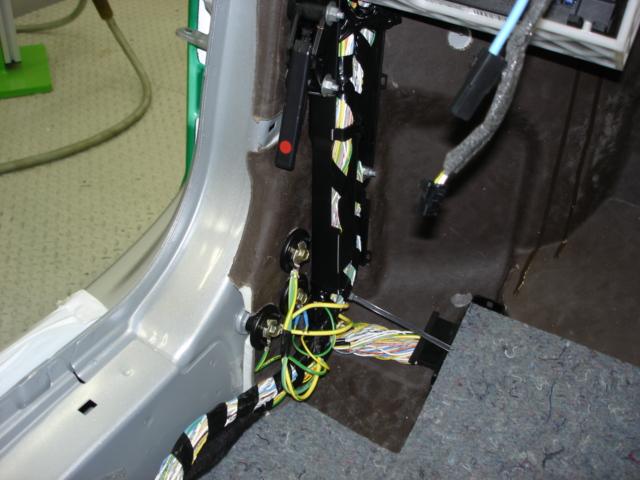
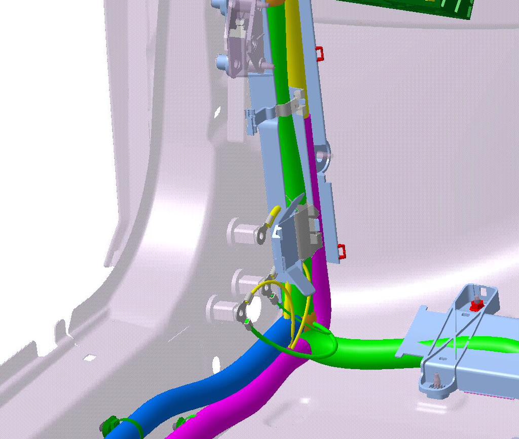
5 Representativeness of CAD data for EMC simulations 5
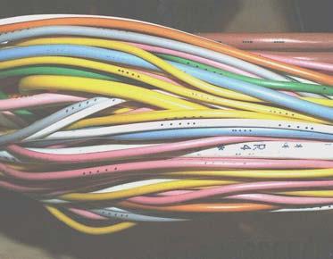
6 General characteristics of an EEA Harnesses are typically non uniform, composed of assembled cables twisted pairs coaxial cables (very few, mainly for RF applications or HV links) shielding (rarely, costly) Signals and power are transmitted and received by an equipment between 2 wires of a same harness (differential mode) or between 1 wire and the car body (common mode) or both alternatively Differential mode + Bat Zero volt conductor Common mode 6


7 Overview of different simulation tools commonly used Frequency-domain Time-domain 3D electromagnetic codes 2D magnetostatic or electrostatic codes Specific tools and codes 2D multi-conductor transmission line codes Electric circuit simulation codes 7
8 General simulation approach Draw a layout of the functional EEA respecting distances, and including ground wires and connections List or include the equipment and the harnesses that may affect the EEA (immunity) or be affected by it (emission) Include the parasitic EMC components Create an interaction matrix Identify for each cell of the matrix the type of coupling modes and evaluate the risk (experience, feed-back, ) For each coupling mode, identify all the components involved Define the goal of the simulation and be sure that the results that will be obtained will lead to a decision and/or a solution Verify that the configurations simulated are acceptable and respect other design rules and requirements (safety, ) List what data is available Introduce assumptions, approximations and simplifications Define what numerical tools can be used Evaluate the time needed (including iterations) to reach the goal Combine and optimize data, tools, methods to succeed before the deadline 8
9 High voltage battery A generic typical electric powertrain AC / DC converter P1 P2 P3 Electric motor Conducted emissions Switching noise Radiated emissions Switching noise up clock + harmonics Conducted emissions Switching noise Fundamental frequency Harmonics Shielding (equipment and cables), filtering, grounding, and connectivity are to be defined 9
10 Electrical features having an EMC impact Power, switching and Pulse Width Modulation Higher levels of current Low rise times (typ. 50μs to avoid power losses in heat) Broadband spectrum, mainly < 100 MHz Increase radiated and conducted emission levels Increase crosstalk Increase point to point voltage drops (common mode) Increase magnetic field levels Ground connections Safety requirements Currents should not use them as a return path!!! 10
11 EMC problems introduced by powertrains Immunity to external sources Normally none on the high voltage part Nothing specific to powertrains on the rest Emission Radio reception (AM, CB, FM, ) Audio systems Systems using low frequency communications (125 khz) Magnetic field sensors (Hall effect and LF) Health protection (Recommendation 1999/519/CE (*) : 6.28 μt between 80 Hz 150 khz) Environment (Directive 2006/28/CE above 30 MHz) (*) Directive 2004/40/CE allows higher levels 11
12 Origin and reasons of the EMC emission problems From the equipment Waveforms Components PCB layout Filtering Shielding Ground connections Location of the equipment From the harnesses Waveforms Impedances Type of cables Connections Bundling Height, length Routing 12
13 Pinpointing the risks using an EMC interaction matrix EMISSION High voltage battery Equipment / Sensors / Antennas Cables / Signals DC link Coupling modes AC / DC converter AC link Electric motor Radiated Conducted Crosstalk Common impedance + Transfer impedance 13
14 Specific EMC questions to address What type of cables are needed? What transfer impedance (or shield effectiveness) is required? Should we group the 3-phase conductors in a single shielded cable? How should the 3-phase conductors be placed between each other? How should the interconnects be done? What should be grounded for EMC reasons? What needs a separate routing? What should be kept outside (beneath) the vehicle? Etc 14
15 Modeling passive linear components L = 10μΗ ( R = 100mΩ, C = 0.1pF)? dbω C = 470pF or 10nF (R = 80mΩ, L = 0.6nH)? dbω Frequency (MHz) Parasitic elements of passive components can often be neglected 15
16 Modeling non-linear or active components (diodes, IGBT, MOS) Most of the components have already a model in electric circuit codes, only the parameters have to be correctly chosen The use of a time-domain electric circuit code implicitly requires to import equivalent models of the entire EMC problem 16
17 Modeling shielded equipment near to vehicle chassis Cable bundle Ground wire Ground connection Vehicle chassis Equipment PCB ground plane Car body ground Harness model PCB Z int C ext Simple impedance and capacitance models can often be used 17
18 Modeling unshielded equipment near to vehicle chassis Cable bundle Ground wire Ground connection Vehicle chassis Equipment PCB ground plane Harness model PCB Car body ground C Simple capacitance model can often be used 18
 1000 100 10 1 0.")
19 Modeling unshielded equipment near to vehicle chassis (cont ) Measurement results Module impédance (Ω) Impedance (Ω) Partial ground plane Full ground plane Fréquence Frequency (MHz) 19
")
 Impedance (Ω) 1000 100")
")
20 Modeling unshielded equipment near to vehicle chassis (cont ) Simulation results Module impédance (Ω) Impedance (Ω) Fréquence (MHz) Frequency (MHz) 20
21 Modeling the steel chassis of the vehicle The permeability of the steel chassis of the vehicle must be taken into account at low frequencies The values are not always given (μ r = 500 is used by default) μ r impacts on : Magnetic field distribution and shielding Skin depth Ground / cables global inductance and resistance Current return path EMC analysis requires to take also into account the thickness of the parts Difficulties to find a 3D code that is capable of Taking into account the permeability Taking into account simultaneously the thickness of the steel sheets of the vehicle (0.7 mm) and the size of the vehicle (4 x 1.5 m) MoM or BEM codes can be used with no thickness and μ r = 1 as first approximation 21

22 Effect of permeability on the magnetic field distribution Cable : Copper σ = Ω -1.m 1 Plate : Steel σ = Ω -1.m 1 T =1 mm R = 5 mm W = 2 m μ r = 1 F = 10 Hz μ r = 500 H = 2 cm Over and under estimations of the magnetic field if μr is not taken into account 22


23 Example of field distribution analysis Cable routing 23

24 Example of field distribution analysis Cable routing (cont ) N 1 N 2 N 3 Side Base N 4 N 5 N 6 Shaft Positions N 4 and 5 are the best solutions 24


25 Example of field distribution analysis Single or dual conductor H = 1 cm 1 conductor H = 1 cm D = 2 cm D = 4 cm H = 2 cm D = 2 cm Below Above Above : Same order or magnitude for 1 or 2 conductors Below : Magnetic fields below are approximately divided by 2 Both : Separation has a stronger impact than height 25
26 ρ μ r Copper = = 1 8 Ω.m δ = Skin depth in the chassis ρ π f μ [m] Roughly 7 times less skin depth ρ μ r = = Steel Ω.m Frequency Copper (mm) Steel (mm) 10 Hz Hz khz khz khz MHz Skin effect starts already above 100 Hz for a thickness of 0.7 mm Requires an even finer mesh within the steel sheets 26
27 Modeling a single conductor above ground plane I(z,t) L dz R dz I(z+dz,t) V(z,t) C dz G dz V(z+dz,t) dz z ( z, t ) V z I z ( z, t ) = = R G I ( z, t ) V ( z, t ) ( z, t ) I L t V C t ( z, t ) V z I z () z = ( R + j ω L )() I z () z = ( G + j ω C ) V () z Lumped elements can be used if the length is small compared to wavelength (< λ / 10), otherwise TL models are required 27
 1.1 1 0.9 0.8 Resistance 7 6.5 6 5.5 Per-unit-length resistance (mω) 0.")
28 Modeling the per-unit-length global inductance and resistance Cable : Copper σ = Ω -1.m 1 Plate : Steel σ = Ω -1.m 1 μ r = 500 T =1 mm R = 1 mm H = 2 cm W = 1.4 m Inductance Per-unit-length inductance ( μh) Resistance Per-unit-length resistance (mω) Frequency (Hz) Inductance and resistance varies below a given frequency depending on the height 28
29 Modeling uniform multi-conductor harnesses above a ground plane L 22 Lossless model example I 2 (t,z) L 12 e C 12 I 1 (t,z) L 11 I 1 (t,z+dz) V 1 (t,z) e C 11 V 1 (t,z+dz) z Lossless time-domain equations z+dz ( ) V 1 I I = L 1 + L 2 I z t t 1 e V V V = C 1 e + C z t t V I I 2 = L 1 + L 2 I ( V V ) V e = C 2 1 e + C z t t z t t Lumped elements allows modeling lossy MCTL in time-domain and frequency domain 2 29
30 30 Modeling uniform multi-conductor harnesses above a ground plane (cont ) + = + = t I L t I L z V t I L t I L z V V 1 (t,z b ) V 1 (t,z a ) I 1 (t,z a ) I 2 (t,z a ) z b z a Frequency-depend lossy MCTL only in frequency domain Lossless time-domain equations + = + = t V C t V C z I t V C t V C z I I 1 (t,z b ) Gray box model

31 Modeling the per-unit-length parameters of uniform multi-conductor harnesses Per-unit-length inductances and resistances must be obtained using a 2D LF magneto dynamic code Per-unit-length capacitances and conductances can be obtained using a 2D electrostatic code or a multi-conductor transmission line code Per-unit-length inductances cannot be derived from the values of the p-u-l capacitances and the propagation velocity 31
32 Modeling non-uniform wire bundles and harnesses Power cable Non uniform harness Power cable Uniform Uniform Uniform Uniform [L1],[R1] [L2],[R2] [L3],[R3] [L4],[R4] [C1],[G1] [C2],[G2] [C3],[G3] [C4],[G4] 32
 One configuration is usually sufficient for low frequencies")
33 Modeling non-uniform wire bundles and harnesses (cont ) different configurations (runs) Common mode current (dba) m harness network 15 conductors 2 cm segmentation Frequency (MHz) One configuration is usually sufficient for low frequencies 33
34 Modeling transfer impedance (and admittance) of shielded cables Ic Vc Vp Ip Transfer impedance Transfer admittance V c = Z z c I c V p = Z z p I p Z t I p Z t I c I c = Y + z c V c I p = + Y z p V p Y t V p Y t V c 34
35 V c = Z z c I c I c = + Y z c V c Modeling transfer impedance (and admittance) of shielded cables Split into to sub-models by introducing current-controlled voltage sources and voltage-controlled current sources V p = Z z p I p I p = + Y z p V p Z t I p Y t V p Z t I c Y t V c V c V p I c I p Z c Z c Z I t Y V t Z I t Y V t p c p c Δz Y c Y c 35

36 Transfer impedance of some coaxial cables The transfer impedance is generally constant below 200 khz 36
37 Modeling the current return path in the vehicle chassis L = 3 m R = 1 mm 17.5 cm H = 2 cm 1 V 17.5 cm W = 1.4 m 37


")

38 Modeling the current return path in the vehicle chassis (cont ) Cable : σ = Ω -1.m 1 Plate : σ = Ω -1.m 1 μ r = 1 No thickness (BEM) 10 Hz 100 Hz 1 khz 10 khz 100 khz Currents concentrate under the cable as frequency increases 38
39 Modeling the current return path in the vehicle chassis (cont ) 17.5 cm 2 m R = 1 mm H = 2 cm 17.5 cm 1 V W = 1.4 m 17.5 cm 39


40 Modeling the current return path in the vehicle chassis (cont ) Cable : σ = Ω -1.m 1 Plate : σ = Ω -1.m 1 μ r = 1 No thickness (BEM) 10 Hz 100 Hz 1 khz 10 khz 100 khz Low frequency limit of the transmission line theory depends mainly on the height and ground impedance 40
41 Compacting in the frequency-domain for interfacing with other codes In the frequency-domain, an entire 1D, 2D or 3D linear model can be compressed into a single admittance coupling matrix Y, obtained by short-circuiting all the terminals of the model and applying successively a voltage at each terminal V i I i Linear system I n I 1 V n I1... In = Y... Yn Y Y 1 n... nn V1... Vn V j I j V 1 I = Y V Often requires special techniques (ex : vector fitting) when imported into time-domain codes 41
42 The easy aspects Most of the EMC problems are in low frequencies Electromagnetic quasi-static behaviors Simplifications are possible The difficulties Summary and conclusions Presence of non-linear components (diodes, MOS, IGBT, ) which require time-domain models and simulations PWM with very short rise- and fall-times compared to long functional periods which can lead to consequent simulation durations Skin effect which is obtained in the frequency-domain is difficult to model in time-domain Converting frequency-domain models for time-domain code requires special techniques Permeability should be taken into account and requires then to mesh the thickness of the chassis of the vehicle Many major parameters are unknown (characteristics of MOS and IGBTs, permeability of the steel, transfer impedances of shielded cables, ) Requires several different codes and interfacing between them 42
Verifying Simulation Results with Measurements. Scott Piper General Motors
 Verifying Simulation Results with Measurements Scott Piper General Motors EM Simulation Software Can be easy to justify the purchase of software packages even costing tens of thousands of dollars Upper
4. THEORETICAL: EMISSION AND SUSCEPTIBILITY. pressure sensor, i.e, via printed-circuit board tracks, internal wiring which acts as an
 4. THEORETICAL: EMISSION AND SUSCEPTIBILITY There are many ways for the electromagnetic-interference to be coupled to the pressure sensor, i.e, via printed-circuit board tracks, internal wiring which acts
10 Safety earthing/grounding does not help EMC at RF
 1of 6 series Webinar #3 of 3, August 28, 2013 Grounding, Immunity, Overviews of Emissions and Immunity, and Crosstalk Contents of Webinar #3 Topics 1 through 9 were covered by the previous two webinars
Introduction to Electromagnetic Compatibility
 Introduction to Electromagnetic Compatibility Second Edition CLAYTON R. PAUL Department of Electrical and Computer Engineering, School of Engineering, Mercer University, Macon, Georgia and Emeritus Professor
Understanding and Optimizing Electromagnetic Compatibility in Switchmode Power Supplies
 Understanding and Optimizing Electromagnetic Compatibility in Switchmode Power Supplies 1 Definitions EMI = Electro Magnetic Interference EMC = Electro Magnetic Compatibility (No EMI) Three Components
EMC of Power Converters
 Alain CHAROY - (0033) 4 76 49 76 76 - a.charoy@aemc.fr EMC EMC of Power Converters Friday 9 May 2014 Electromagnetism is just electricity Converters are particularly concerned with EMC: Conducted disturbances
150Hz to 1MHz magnetic field coupling to a typical shielded cable above a ground plane configuration
 150Hz to 1MHz magnetic field coupling to a typical shielded cable above a ground plane configuration D. A. Weston Lowfreqcablecoupling.doc 7-9-2005 The data and information contained within this report
A VIEW OF ELECTROMAGNETIC LIFE ABOVE 100 MHz
 A VIEW OF ELECTROMAGNETIC LIFE ABOVE 100 MHz An Experimentalist's Intuitive Approach Lothar O. (Bud) Hoeft, PhD Consultant, Electromagnetic Effects 5012 San Pedro Ct., NE Albuquerque, NM 87109-2515 (505)
Automotive EMC. IEEE EMC Society Melbourne Chapter October 13, 2010 By Mark Steffka IEEE EMCS Distinguished Lecturer
 Automotive EMC IEEE EMC Society Melbourne Chapter October 13, 2010 By Mark Steffka IEEE EMCS Distinguished Lecturer Email: msteffka@ieee.org IEEE 1 Automotive Systems Past and Present Today s vehicles
Lab Manual Experiment No. 2
 Lab Manual Experiment No. 2 Aim of Experiment: Observe the transient phenomenon of terminated coaxial transmission lines in order to study their time domain behavior. Requirement: You have to install a
From IC characterization to system simulation by systematic modeling bottom up approach
 From IC characterization to system simulation by systematic modeling bottom up approach Frédéric Lafon, François de Daran VALEO VIC, Rue Fernand Pouillon, 944 Creteil Cedex, France, frederic.lafon@valeo.com
Γ L = Γ S =
 TOPIC: Microwave Circuits Q.1 Determine the S parameters of two port network consisting of a series resistance R terminated at its input and output ports by the characteristic impedance Zo. Q.2 Input matching
Chapter 16 PCB Layout and Stackup
 Chapter 16 PCB Layout and Stackup Electromagnetic Compatibility Engineering by Henry W. Ott Foreword The PCB represents the physical implementation of the schematic. The proper design and layout of a printed
(i) Determine the admittance parameters of the network of Fig 1 (f) and draw its - equivalent circuit.
 Determine the admittance parameters of the network of Fig 1 (f) and draw its - equivalent circuit.") I.E.S-(Conv.)-1995 ELECTRONICS AND TELECOMMUNICATION ENGINEERING PAPER - I Some useful data: Electron charge: 1.6 10 19 Coulomb Free space permeability: 4 10 7 H/m Free space permittivity: 8.85 pf/m Velocity
I.E.S-(Conv.)-1995 ELECTRONICS AND TELECOMMUNICATION ENGINEERING PAPER - I Some useful data: Electron charge: 1.6 10 19 Coulomb Free space permeability: 4 10 7 H/m Free space permittivity: 8.85 pf/m Velocity
ELECTROMAGNETIC COMPATIBILITY HANDBOOK 1. Chapter 8: Cable Modeling
 ELECTROMAGNETIC COMPATIBILITY HANDBOOK 1 Chapter 8: Cable Modeling Related to the topic in section 8.14, sometimes when an RF transmitter is connected to an unbalanced antenna fed against earth ground
Advanced Topics in EMC Design. Issue 1: The ground plane to split or not to split?
 NEEDS 2006 workshop Advanced Topics in EMC Design Tim Williams Elmac Services C o n s u l t a n c y a n d t r a i n i n g i n e l e c t r o m a g n e t i c c o m p a t i b i l i t y e-mail timw@elmac.co.uk
T + T /13/$ IEEE 236. the inverter s input impedances on the attenuation of a firstorder
 Emulation of Conducted Emissions of an Automotive Inverter for Filter Development in HV Networks M. Reuter *, T. Friedl, S. Tenbohlen, W. Köhler Institute of Power Transmission and High Voltage Technology
Chapter 5 Electromagnetic interference in flash lamp pumped laser systems
 Chapter 5 Electromagnetic interference in flash lamp pumped laser systems This chapter presents the analysis and measurements of radiated near and far fields, and conducted emissions due to interconnects
Non-Ideal Behavior of Components
 Non-Ideal Behavior of Components Todd H. Hubing Dept. of Electrical and Computer Engineering Clemson, University Clemson, SC 29634 USA email: hubing@clemson.edu Telephone: 1-864-656-7219 Circuit Schematics
Application Note AN- 1094
 Application Note AN- 194 High Frequency Common Mode Analysis of Drive Systems with IRAMS Power Modules Cesare Bocchiola Table of Contents Page Section 1 : Introduction...2 Section 2 : The Conducted EMI
Class-D Audio Power Amplifiers: PCB Layout For Audio Quality, EMC & Thermal Success (Home Entertainment Devices)
") Class-D Audio Power Amplifiers: PCB Layout For Audio Quality, EMC & Thermal Success (Home Entertainment Devices) Stephen Crump http://e2e.ti.com Audio Power Amplifier Applications Audio and Imaging Products
Class-D Audio Power Amplifiers: PCB Layout For Audio Quality, EMC & Thermal Success (Home Entertainment Devices) Stephen Crump http://e2e.ti.com Audio Power Amplifier Applications Audio and Imaging Products
Electromagnetic Compatibility
 Electromagnetic Compatibility Introduction to EMC International Standards Measurement Setups Emissions Applications for Switch-Mode Power Supplies Filters 1 What is EMC? A system is electromagnetic compatible
EMC Simulation of Consumer Electronic Devices
 of Consumer Electronic Devices By Andreas Barchanski Describing a workflow for the EMC simulation of a wireless router, using techniques that can be applied to a wide range of consumer electronic devices.
Automotive Systems Past and Present
 Automotive EMC IEEE EMC Society Eastern North Carolina Section February 9, 2010 By Mark Steffka IEEE EMCS Distinguished Lecturer Email: msteffka@ieee.org IEEE 1 Automotive Systems Past and Present Today
Solution of EMI Problems from Operation of Variable-Frequency Drives
 Pacific Gas and Electric Company Solution of EMI Problems from Operation of Variable-Frequency Drives Background Abrupt voltage transitions on the output terminals of a variable-frequency drive (VFD) are
INVENTION DISCLOSURE- ELECTRONICS SUBJECT MATTER IMPEDANCE MATCHING ANTENNA-INTEGRATED HIGH-EFFICIENCY ENERGY HARVESTING CIRCUIT
 INVENTION DISCLOSURE- ELECTRONICS SUBJECT MATTER IMPEDANCE MATCHING ANTENNA-INTEGRATED HIGH-EFFICIENCY ENERGY HARVESTING CIRCUIT ABSTRACT: This paper describes the design of a high-efficiency energy harvesting
OPEN SOURCE CABLE MODELS FOR EMI SIMULATIONS
 OPEN SOURCE CABLE MODELS FOR EMI SIMULATIONS S. Greedy 1, C. Smartt 1, D. W. P. Thomas 1. 1 : George Green Institute for Electromagnetics Research, Department of Electrical and Electronic Engineering,
BASIS OF ELECTROMAGNETIC COMPATIBILITY OF INTEGRATED CIRCUIT Chapter VI - MODELLING PCB INTERCONNECTS Corrections of exercises
 BASIS OF ELECTROMAGNETIC COMPATIBILITY OF INTEGRATED CIRCUIT Chapter VI - MODELLING PCB INTERCONNECTS Corrections of exercises I. EXERCISE NO 1 - Spot the PCB design errors Spot the six design errors in
Design for Guaranteed EMC Compliance
 Clemson Vehicular Electronics Laboratory Reliable Automotive Electronics Automotive EMC Workshop April 29, 2013 Design for Guaranteed EMC Compliance Todd Hubing Clemson University EMC Requirements and
Course Introduction Purpose Objectives Content Learning Time
 Course Introduction Purpose This course discusses techniques for analyzing and eliminating noise in microcontroller (MCU) and microprocessor (MPU) based embedded systems. Objectives Learn about a method
Objectives of transmission lines
 Introduction to Transmission Lines Applications Telephone Cable TV (CATV, or Community Antenna Television) Broadband network High frequency (RF) circuits, e.g., circuit board, RF circuits, etc. Microwave
Chapter 12 Digital Circuit Radiation. Electromagnetic Compatibility Engineering. by Henry W. Ott
 Chapter 12 Digital Circuit Radiation Electromagnetic Compatibility Engineering by Henry W. Ott Forward Emission control should be treated as a design problem from the start, it should receive the necessary
ELEC Course Objectives/Proficiencies
 Lecture 1 -- to identify (and list examples of) intentional and unintentional receivers -- to list three (broad) ways of reducing/eliminating interference -- to explain the differences between conducted/radiated
Chapter 12: Transmission Lines. EET-223: RF Communication Circuits Walter Lara
 Chapter 12: Transmission Lines EET-223: RF Communication Circuits Walter Lara Introduction A transmission line can be defined as the conductive connections between system elements that carry signal power.
EMC cases study. Antonio Ciccomancini Scogna, CST of America CST COMPUTER SIMULATION TECHNOLOGY
 EMC cases study Antonio Ciccomancini Scogna, CST of America antonio.ciccomancini@cst.com Introduction Legal Compliance with EMC Standards without compliance products can not be released to the market Failure
11 Myths of EMI/EMC ORBEL.COM. Exploring common misconceptions and clarifying them. MYTH #1: EMI/EMC is black magic.
 11 Myths of EMI/EMC Exploring common misconceptions and clarifying them By Ed Nakauchi, Technical Consultant, Orbel Corporation What is a myth? A myth is defined as a popular belief or tradition that has
A Simple Wideband Transmission Line Model
 A Simple Wideband Transmission Line Model Prepared by F. M. Tesche Holcombe Dept. of Electrical and Computer Engineering College of Engineering & Science 337 Fluor Daniel Building Box 34915 Clemson, SC
Brief Overview of EM Computational Modeling Techniques for Real-World Engineering Problems
 Brief Overview of EM Computational Modeling Techniques for Real-World Engineering Problems Bruce Archambeault, Ph.D. IEEE Fellow, IBM Distinguished Engineer Emeritus Bruce@brucearch.com Archambeault EMI/EMC
EMC Overview. What is EMC? Why is it Important? Case Studies. Examples of calculations used in EMC. EMC Overview 1
 EMC Overview What is EMC? Why is it Important? Case Studies. Examples of calculations used in EMC. EMC Overview 1 What Is EMC? Electromagnetic Compatibility (EMC): The process of determining the interaction
VLSI is scaling faster than number of interface pins
 High Speed Digital Signals Why Study High Speed Digital Signals Speeds of processors and signaling Doubled with last few years Already at 1-3 GHz microprocessors Early stages of terahertz Higher speeds
 VALLIAMMAI ENGINEERING COLLEGE SRM Nagar, Kattankulathur-603 203 DEPARTMENT OF ELECTRONICS AND COMMUNICATION ENGINEERING EC6503 TRANSMISSION LINES AND WAVEGUIDES YEAR / SEMESTER: III / V ACADEMIC YEAR:
A Comparison Between MIL-STD and Commercial EMC Requirements Part 2. By Vincent W. Greb President, EMC Integrity, Inc.
 A Comparison Between MIL-STD and Commercial EMC Requirements Part 2 By Vincent W. Greb President, EMC Integrity, Inc. OVERVIEW Compare and contrast military (i.e., MIL-STD) and commercial EMC immunity
Common myths, fallacies and misconceptions in Electromagnetic Compatibility and their correction.
 Common myths, fallacies and misconceptions in Electromagnetic Compatibility and their correction. D. A. Weston EMC Consulting Inc 22-3-2010 These are some of the commonly held beliefs about EMC which are
Course Introduction. Content 16 pages. Learning Time 30 minutes
 Course Introduction Purpose This course discusses techniques for analyzing and eliminating noise in microcontroller (MCU) and microprocessor (MPU) based embedded systems. Objectives Learn what EMI is and
Analogue circuit design for RF immunity
 Analogue circuit design for RF immunity By EurIng Keith Armstrong, C.Eng, FIET, SMIEEE, www.cherryclough.com First published in The EMC Journal, Issue 84, September 2009, pp 28-32, www.theemcjournal.com
Ileana-Diana Nicolae ICMET CRAIOVA UNIVERSITY OF CRAIOVA MAIN BUILDING FACULTY OF ELECTROTECHNICS
 The Designing, Realization and Testing of a Network Filter used to Reduce Electromagnetic Disturbances and to Improve the EMI for Static Switching Equipment Petre-Marian Nicolae Ileana-Diana Nicolae George
EC Transmission Lines And Waveguides
 EC6503 - Transmission Lines And Waveguides UNIT I - TRANSMISSION LINE THEORY A line of cascaded T sections & Transmission lines - General Solution, Physical Significance of the Equations 1. Define Characteristic
Liquidmetal Electromagnetic Properties & RF Shielding Overview
 Liquidmetal Electromagnetic Properties & RF Shielding Overview Liquidmetal alloy is more transparent to RF signals than many similar materials 1 Introduction H ow a material interacts with radio frequency
The Ground Myth IEEE. Bruce Archambeault, Ph.D. IBM Distinguished Engineer, IEEE Fellow 18 November 2008
 The Ground Myth Bruce Archambeault, Ph.D. IBM Distinguished Engineer, IEEE Fellow barch@us.ibm.com 18 November 2008 IEEE Introduction Electromagnetics can be scary Universities LOVE messy math EM is not
Applications & Cases. EPCOS AG A TDK Group Company Edition
 Applications & Cases Reference Firs EPCOS AG A TDK Group Company Edition 2018 www.epcos.com 1 / 11 egrated solution for inverters to be used in e-mobility powertrains and industrial applications. The design
nan Small loop antennas APPLICATION NOTE 1. General 2. Loop antenna basics
 nan400-03 1. General For F designers developing low-power radio devices for short-range applications, antenna design has become an important issue for the total radio system design. Taking the demand for
CHAPTER 2. Basic Concepts, Three-Phase Review, and Per Unit
 CHAPTER 2 Basic Concepts, Three-Phase Review, and Per Unit 1 AC power versus DC power DC system: - Power delivered to the load does not fluctuate. - If the transmission line is long power is lost in the
Time-Domain Coupling Analysis of Shielded Cable on the Ground Excited by Plane Wave
 Progress In Electromagnetics Research M, Vol. 67, 45 53, 018 Time-Domain Coupling Analysis of Shielded Cable on the Ground Excited by Plane Wave Zhihong Ye 1, *, Cheng Liao, and Chuan Wen 1 Abstract This
EC TRANSMISSION LINES AND WAVEGUIDES TRANSMISSION LINES AND WAVEGUIDES
 TRANSMISSION LINES AND WAVEGUIDES UNIT I - TRANSMISSION LINE THEORY 1. Define Characteristic Impedance [M/J 2006, N/D 2006] Characteristic impedance is defined as the impedance of a transmission line measured
ENERGY CABLE MODELING UNDER POWER ELECTRONIC CONVERTER CONSTRAINTS
 ENERGY CABLE MODELING UNDER POWER ELECTRONIC CONVERTER CONSTRAINTS Yannick WEENS, USTL - L2EP, (France), yannick.weens@ed-univ-lille1.fr Nadir IDIR, USTL - L2EP, (France), nadir.idir@univ-lille1.fr Jean
Modeling of an EMC Test-bench for Conducted Emissions in Solid State Applications
 Modeling of an EMC Test-bench for Conducted Emissions in Solid State Applications A.Micallef, C.Spiteri Staines and M.Apap Department of Industrial Electrical Power Conversion University of Malta Malta
A Few (Technical) Things You Need To Know About Using Ethernet Cable for Portable Audio
 Things You Need To Know About Using Ethernet Cable for Portable Audio") A Few (Technical) Things You Need To Know About Using Ethernet Cable for Portable Audio Rick Rodriguez June 1, 2013 Digital Audio Data Transmission over Twisted-Pair This paper was written to introduce
A Few (Technical) Things You Need To Know About Using Ethernet Cable for Portable Audio Rick Rodriguez June 1, 2013 Digital Audio Data Transmission over Twisted-Pair This paper was written to introduce
Waveguides. Metal Waveguides. Dielectric Waveguides
 Waveguides Waveguides, like transmission lines, are structures used to guide electromagnetic waves from point to point. However, the fundamental characteristics of waveguide and transmission line waves
Novel Modeling Strategy for a BCI set-up applied in an Automotive Application
 Novel Modeling Strategy for a BCI set-up applied in an Automotive Application An industrial way to use EM simulation tools to help Hardware and ASIC designers to improve their designs for immunity tests.
University of KwaZulu-Natal
 University of KwaZulu-Natal School of Engineering Electrical, Electronic & Computer Engineering Instructions to Candidates: UNIVERSITY EXAMINATIONS DECEMBER 2016 ENEL3EM: EM THEORY Time allowed: 2 hours
Techniques to reduce electromagnetic noise produced by wired electronic devices
 Rok / Year: Svazek / Volume: Číslo / Number: Jazyk / Language 2016 18 5 EN Techniques to reduce electromagnetic noise produced by wired electronic devices - Tomáš Chvátal xchvat02@stud.feec.vutbr.cz Faculty
Application Note # 5438
 Application Note # 5438 Electrical Noise in Motion Control Circuits 1. Origins of Electrical Noise Electrical noise appears in an electrical circuit through one of four routes: a. Impedance (Ground Loop)
Experiment 4: Grounding and Shielding
 4-1 Experiment 4: Grounding and Shielding Power System Hot (ed) Neutral (White) Hot (Black) 115V 115V 230V Ground (Green) Service Entrance Load Enclosure Figure 1 Typical residential or commercial AC power
Lecture 4. Maximum Transfer of Power. The Purpose of Matching. Lecture 4 RF Amplifier Design. Johan Wernehag Electrical and Information Technology
 Johan Wernehag, EIT Lecture 4 RF Amplifier Design Johan Wernehag Electrical and Information Technology Design of Matching Networks Various Purposes of Matching Voltage-, Current- and Power Matching Design
Investigation of Electromagnetic Field Coupling from DC-DC Buck Converters to Automobile AM/FM Antennas
 CST North American Automotive Workshop Investigation of Electromagnetic Field Coupling from DC-DC Buck Converters to Automobile AM/FM Antennas Patrick DeRoy, CST of America, Framingham, Massachusetts,
3 GHz Wide Frequency Model of Surface Mount Technology (SMT) Ferrite Bead for Power/Ground and I/O Line Noise Simulation of High-speed PCB
 Ferrite Bead for Power/Ground and I/O Line Noise Simulation of High-speed PCB") 3 GHz Wide Frequency Model of Surface Mount Technology (SMT) Ferrite Bead for Power/Ground and I/O Line Noise Simulation of High-speed PCB Tae Hong Kim, Hyungsoo Kim, Jun So Pak, and Joungho Kim Terahertz
3 GHz Wide Frequency Model of Surface Mount Technology (SMT) Ferrite Bead for Power/Ground and I/O Line Noise Simulation of High-speed PCB Tae Hong Kim, Hyungsoo Kim, Jun So Pak, and Joungho Kim Terahertz
Extraction of Transmission Line Parameters and Effect of Conductive Substrates on their Characteristics
 ROMANIAN JOURNAL OF INFORMATION SCIENCE AND TECHNOLOGY Volume 19, Number 3, 2016, 199 212 Extraction of Transmission Line Parameters and Effect of Conductive Substrates on their Characteristics Saurabh
Categorized by the type of core on which inductors are wound:
 Inductors Categorized by the type of core on which inductors are wound: air core and magnetic core. The magnetic core inductors can be subdivided depending on whether the core is open or closed. Equivalent
Impedance Analysis of Automotive High Voltage Networks for EMC Measurements
 Impedance Analysis of Automotive High Voltage Networks for EMC Measurements Dipl.-Ing. M. Reuter *, Prof. Dr.-Ing. S. Tenbohlen, Dr.-Ing. W. Köhler, Dipl.-Ing. A. udwig Institute of Power Transmission
CHAPTER 6 CARBON NANOTUBE AND ITS RF APPLICATION
 CHAPTER 6 CARBON NANOTUBE AND ITS RF APPLICATION 6.1 Introduction In this chapter we have made a theoretical study about carbon nanotubes electrical properties and their utility in antenna applications.
Influence of Termination Impedance on conducted Emissions in Automotive High Voltage Networks
 Influence of Termination Impedance on conducted Emissions in Automotive High Voltage Networks M. Reuter *, S. Tenbohlen, W. Koehler Institute of Power Transmission and High Voltage Technology (IEH), University
About the High-Frequency Interferences produced in Systems including PWM and AC Motors
 About the High-Frequency Interferences produced in Systems including PWM and AC Motors ELEONORA DARIE Electrotechnical Department Technical University of Civil Engineering B-dul Pache Protopopescu 66,
TABLE OF CONTENTS 1 Fundamentals Transmission Line Parameters... 29
 TABLE OF CONTENTS 1 Fundamentals... 1 1.1 Impedance of Linear, Time-Invariant, Lumped-Element Circuits... 1 1.2 Power Ratios... 2 1.3 Rules of Scaling... 5 1.3.1 Scaling of Physical Size... 6 1.3.1.1 Scaling
CHAPTER 6 EMI EMC MEASUREMENTS AND STANDARDS FOR TRACKED VEHICLES (MIL APPLICATION)
") 147 CHAPTER 6 EMI EMC MEASUREMENTS AND STANDARDS FOR TRACKED VEHICLES (MIL APPLICATION) 6.1 INTRODUCTION The electrical and electronic devices, circuits and systems are capable of emitting the electromagnetic
147 CHAPTER 6 EMI EMC MEASUREMENTS AND STANDARDS FOR TRACKED VEHICLES (MIL APPLICATION) 6.1 INTRODUCTION The electrical and electronic devices, circuits and systems are capable of emitting the electromagnetic
Overview of EMC Regulations and Testing. Prof. Tzong-Lin Wu Department of Electrical Engineering National Taiwan University
 Overview of EMC Regulations and Testing Prof. Tzong-Lin Wu Department of Electrical Engineering National Taiwan University What is EMC Electro-Magnetic Compatibility ( 電磁相容 ) EMC EMI (Interference) Conducted
Introduction: Planar Transmission Lines
 Chapter-1 Introduction: Planar Transmission Lines 1.1 Overview Microwave integrated circuit (MIC) techniques represent an extension of integrated circuit technology to microwave frequencies. Since four
Large E Field Generators in Semi-anechoic Chambers for Full Vehicle Immunity Testing
 Large E Field Generators in Semi-anechoic Chambers for Full Vehicle Immunity Testing Vince Rodriguez ETS-Lindgren, Inc. Abstract Several standards recommend the use of transmission line systems (TLS) as
ELEC 0017: ELECTROMAGNETIC COMPATIBILITY LABORATORY SESSIONS
 Academic Year 2015-2016 ELEC 0017: ELECTROMAGNETIC COMPATIBILITY LABORATORY SESSIONS V. BEAUVOIS P. BEERTEN C. GEUZAINE 1 CONTENTS: EMC laboratory session 1: EMC tests of a commercial Christmas LED light
Differential-Mode Emissions
 Differential-Mode Emissions In Fig. 13-5, the primary purpose of the capacitor C F, however, is to filter the full-wave rectified ac line voltage. The filter capacitor is therefore a large-value, high-voltage
EUA2011A. Low EMI, Ultra-Low Distortion, 2.5-W Mono Filterless Class-D Audio Power Amplifier DESCRIPTION FEATURES APPLICATIONS
 Low EMI, Ultra-Low Distortion, 2.5-W Mono Filterless Class-D Audio Power Amplifier DESCRIPTION The EUA2011A is a high efficiency, 2.5W mono class-d audio power amplifier. A new developed filterless PWM
EC6503 Transmission Lines and WaveguidesV Semester Question Bank
 UNIT I TRANSMISSION LINE THEORY A line of cascaded T sections & Transmission lines General Solution, Physicasignificance of the equations 1. Derive the two useful forms of equations for voltage and current
Coupling modes. Véronique Beauvois, Ir Copyright 2015 Véronique Beauvois, ULg
 Coupling modes Véronique Beauvois, Ir. 2015-2016 General problem in EMC = a trilogy Parameters Amplitude Spectrum Source (disturbing) propagation Coupling modes Victim (disturbed) lightning electrostatic
Technology in Balance
 Technology in Balance A G1 G2 B Basic Structure Comparison Regular capacitors have two plates or electrodes surrounded by a dielectric material. There is capacitance between the two conductive plates within
Presented by Joanna Hill
 Santa Clara IEEE EMC Chapter meeting April 9, 2013 Dorothy we're not in Kansas any more, we are in Impedance land. Oh my! Presented by Joanna Hill Cell 248-765-3599 jhill28590@comcast.net Welcome to Impedance
Analysis of Laddering Wave in Double Layer Serpentine Delay Line
 International Journal of Applied Science and Engineering 2008. 6, 1: 47-52 Analysis of Laddering Wave in Double Layer Serpentine Delay Line Fang-Lin Chao * Chaoyang University of Technology Taichung, Taiwan
External Drive Hardware
 US1086e_External Drive Hardware, 08/2010 External Drive Hardware Selection and Application Answers Answers to external hardware questions A soup to nuts list of questions with installation / application
Single-turn and multi-turn coil domains in 3D COMSOL. All rights reserved.
 Single-turn and multi-turn coil domains in 3D 2012 COMSOL. All rights reserved. Introduction This tutorial shows how to use the Single-Turn Coil Domain and Multi-Turn Coil Domain features in COMSOL s Magnetic
Parasitic Component Extraction and EMI Reduction Techniques in an Power Electric Drive System
 Parasitic Component Extraction and EMI Reduction Techniques in an Power Electric Drive System Master s Thesis in the Master s programme in Electric Power Engineering HÄRSJÖ, JOACHIM Department of Energy
Suppression Techniques using X2Y as a Broadband EMI Filter IEEE International Symposium on EMC, Boston, MA
 Suppression Techniques using X2Y as a Broadband EMI Filter Jim Muccioli Tony Anthony Dave Anthony Dale Sanders X2Y Attenuators, LLC Erie, PA 16506-2972 www.x2y.com Email: x2y@x2y.com Bart Bouma Yageo/Phycomp
Efficient HF Modeling and Model Parameterization of Induction Machines for Time and Frequency Domain Simulations
 Efficient HF Modeling and Model Parameterization of Induction Machines for Time and Frequency Domain Simulations M. Schinkel, S. Weber, S. Guttowski, W. John Fraunhofer IZM, Dept.ASE Gustav-Meyer-Allee
"Natural" Antennas. Mr. Robert Marcus, PE, NCE Dr. Bruce C. Gabrielson, NCE. Security Engineering Services, Inc. PO Box 550 Chesapeake Beach, MD 20732
 Published and presented: AFCEA TEMPEST Training Course, Burke, VA, 1992 Introduction "Natural" Antennas Mr. Robert Marcus, PE, NCE Dr. Bruce C. Gabrielson, NCE Security Engineering Services, Inc. PO Box
Improving conducted EMI forecasting with accurate layout modeling
 Improving conducted EMI forecasting with accurate layout modeling M. Lionet*, R. Prades*, X. Brunotte*,Y. Le Floch*, E. Clavel**, J.L. Schanen**, J.M. Guichon** *CEDRAT, 15 chemin de Malacher - F- 38246
AC Motor Drives EMC Standard Installation Guide EMC Compliance Practice
 http://www.delta.com.tw/industrialautomation/ AC Motor Drives EMC Standard Installation Guide EMC Compliance Practice i Preface When an AC motor drive is installed in a noisy environment, radiated and/or
University of KwaZulu-Natal
 University of KwaZulu-Natal School of Engineering Electrical, Electronic & Computer Engineering UNIVERSITY EXAMINATIONS NOVEMBER 2015 ENEL3EM: EM THEORY Time allowed: 2 hours Instructions to Candidates:
CHAPTER 4. Practical Design
 CHAPTER 4 Practical Design The results in Chapter 3 indicate that the 2-D CCS TL can be used to synthesize a wider range of characteristic impedance, flatten propagation characteristics, and place passive
Solutions for EMC Issues in Automotive System Transmission Lines
 June 23, 2010 Solutions for EMC Issues in Automotive System Transmission Lines FTF-ENT-F0174 Todd Hubing Clemson University and VortiQa are trademarks of Freescale Semiconductor, Inc. All other product
High-Speed PCB Design und EMV Minimierung
 TRAINING Bei dem hier beschriebenen Training handelt es sich um ein Cadence Standard Training. Sie erhalten eine Dokumentation in englischer Sprache. Die Trainingssprache ist deutsch, falls nicht anders
Type Ordering Code Package TDA Q67000-A5168 P-DIP-18-5
 Video Modulator for FM-Audio TDA 5666-5 Preliminary Data Bipolar IC Features FM-audio modulator Sync level clamping of video input signal Controlling of peak white value Continuous adjustment of modulation
Common and Differential Mode EMI Filters for Power Electronics
 SPEEDAM 28 International Symposium on Power Electronics, Electrical Drives, Automation and Motion Common and Differential Mode EMI Filters for Power Electronics V. Serrao, A. Lidozzi, L. Solero and A.
ELECTROMAGNETIC SHIELDING HANDBOOK FOR WIRED AND WIRELESS EMC APPLICATIONS
 ELECTROMAGNETIC SHIELDING HANDBOOK FOR WIRED AND WIRELESS EMC APPLICATIONS by Anatoly Tsaliovich Kluwer Academic Publishers Boston / London / Dordrecht Contents Foreword Preface xiii xvii 1. INTRODUCTION