Presented by Joanna Hill
|
|
|
- Annabella Golden
- 6 years ago
- Views:
Transcription

1 Santa Clara IEEE EMC Chapter meeting April 9, 2013 Dorothy we're not in Kansas any more, we are in Impedance land. Oh my! Presented by Joanna Hill Cell
2 Welcome to Impedance land You don t have to be crazy to be into EMC.
3 Welcome to Impedance land You don t have to be crazy to be into EMC. We will train you!
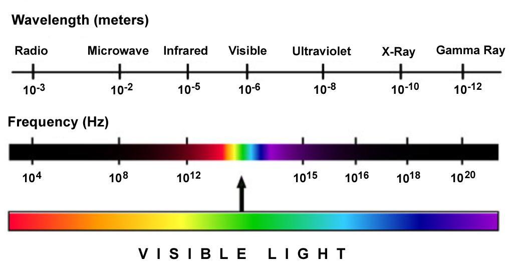
4 The Electromagnetic Spectrum
5 According to Wikipedia: What is Wavelength? The distance over which the wave's shape repeats. To the RF and EMC engineer: It is the distance travelled by the propagating wave in one cycle. c f Wavelength Wavelength
6 When working an EMC issue, It s all the same stuff Distance Phase Inductance

7 When working an EMC issue, It s all the same stuff Distance Phase Inductance The secret to understanding EMC is understanding wavelength as it relates to these three items.
8 c Wavelength expressed in free space 8 3x10 meters /sec 300 x10 6 c f 11 3 x10 mm/ sec 9 f in GHz x10 300mm f ( GHz) 11.8inches f ( GHz) We can also say the wave travels 11.8 inches in one nanosecond.
9 Wavelength expressed with stuff in the space Permeability 0 r H m Permittivity 0 r F m v 1 c r r not freespace v not freespace f
10 Wavelength expressed with FR4 PCB in the space v FR 4 PCB 0.48c 144 mm nsec 5.9 inches nsec FR vfr 4PCB 5.9inches / nsec 4PCB f f ( GHz) We can also say that in FR4 PCB material the wave travels 5.9 inches in one nanosecond.
11 There is a lot to be learned from Figure 9-17 A dimensionally correct half wavelength Dipole is not resonant. Z 73 j42. 5 It is electrically too long. From Antennas Third Edition by Kraus & Marhefka, page 320
12 There is a lot to be learned from Figure 9-17 The length of a resonant dipole depends on the diameter of the conductors. D L Z 67 j0 From Antennas Third Edition by Kraus & Marhefka, page 320
13 There is a lot to be learned from Figure 9-17 A hole in a conductor can also be a resonant antenna. Z 50 j 0 From Antennas Third Edition by Kraus & Marhefka, page 320
14 There is a lot to be learned from Figure 9-17 To get this hole in a sheet of conductor to resonate at 500 MHz, the slot would need to be 555 mm wide and have a width of 40 mm. 3 L 0.925* Meters 5 3 L 0.925* Meters 555mm 5 3 w0.066* Meters 40mm 5 From Antennas Third Edition by Kraus & Marhefka, page 320
15 SPICE simulation of a loop DC 3Meters 3 2 Meters 1Meters 3 4 Meters 3Meters 3 6 Meters
16 SPICE simulation of a Monopole MHz 3Meters 300 MHz 1Meters 500 MHz 3 5 Meters

17 We measure the resonance frequency of a Monopole antenna with a Network Analyzer We measure the S11, reflection coefficient, of a 100 MHz monopole antenna. The reflection coefficient is a measure of the amount of energy that leaves the antenna verses the energy that is reflected back to the analyzer. As various materials are presented to the antenna, we watch how the S11 changes.


18 The Good, the Bad and the Ugly. Good Ground. Bad Ground Holes in the ground. Ugly Ground Daisy-chained.


19 The Good, the Bad and the Ugly. Good Ground. Bad Ground Holes in the ground. Ugly Ground Daisy-chained.
20 The Good, the Bad and the Ugly. The Daisy-chained ground trace, shown in yellow, has a common mode impedance with the clock shown in purple. The microcontroller clock trace is shown in red. The load capacitors provide the offending common mode current shown in blue.
21 The Good, the Bad and the Ugly. The Daisy-chained ground trace, shown in yellow, forms an asymmetric dipole antenna feed by the common mode impedance of the clock.

22 The Good, the Bad and the Ugly. We break the antenna by removing the Daisy-chained ground trace and replacing it with a ground plane.

23 The Good, the Bad and the Ugly. Yes a full ground plane was implemented in only two layers. The ground is stitched from top to bottom forming a sheet of ground with small holes.
24 Lots of people have the paradigm that adding capacitors is a good thing. But adding capacitors often adds to your troubles by adding new resonances. You end up playing a game of Capacitor Whack-a-Mole.
25 Let s take a look at two capacitors and the distances between them.
26 Let s take a look at two capacitors and the distances between them. There is one resonance and one loop of current. Frequency L 2 1 FR 4 PCB 15 L T C T nh inch
27 Now let s take a look at an array of three capacitors and the distances between them.
28 Now let s take a look at an array of three capacitors and the distances between them.
29 Now let s take a look at an array of three capacitors and the distances between them.
30 Now let s take a look at an array of three capacitors and the distances between them.
31 Now let s take a look at an array of three capacitors and the distances between them. We now have three resonances.
32 But what happens as we add a fourth capacitor?
33 We get ten different resonance frequencies.
34 And we get twelve common mode paths of resonance current.
35 Hence adding lots of capacitors is not the answer to EMC problem mitigation. Because as capacitors are added you end up playing a game of Capacitor Whack-a-Mole.


36 Hence adding lots of capacitors is not the answer to EMC problem mitigation. So what do we do? We find and break the loop antennas.


37 Pin the tail on the tank circuit. Switch matrix inputs are very common. Can you find the tank circuit?
38 Pin the tail on the tank circuit. Here s a hint: with a higher value of R105 the EMC performance got worse.
39 Let s find the components. The traces are the inductors. The open switch is a capacitor. The microcontroller input is also a capacitor. And if the diode is off, it is also a capacitor.


40 Pin the tail on the tank circuit. First we need to know the capacitance of the Diode.


41 The Rohm Data sheet With the diode off the maximum capacitance is 3.5 pf.
42 The Tank s resonant frequency The total length to the switch through cables and PCB then back again is 20 inches C T 0.5 pf 7 pf 3. 5 pf C T 2. 4 pf 15nH L T *20 Inches 300nH Inch 1 Frequency center 188MHz 2 300nH 2.4 ph
43 I like to be a good witch by adding a resistor The only DC current in the resistors is the input leakage current. The High Q tank is now a low Q tank and the emissions have been reduced by a substantial amount. Presented with respect for those of the Wiccan Faith.
44 When the wavelength of the emission is physically much larger than the dimensions of the radiating element, the emitted field strength of a known current can be estimated using the Schelkunoff equations. The emission of a small loop of current I can be estimated of a loop in the X Y plane of E E Small Loop ShortWire Area, at an angle down from the Z axis of σ, and measured at a distance d freq 2 c d Area I The emission of a short wire of current I can be estimated of a small conductor area in Z axis, at an angle down from the Z axis of σ, and measured at a distance d. 120 freq I Length 2 c d 2 c 1 2 freq d c 1 2 freq d 2 sin c 2 freq d 4 sin Derived from equations found in Controlling Radiated Emission by Design second edition by Michel Mardiguian and Applied Electromagnetics and Electromagnetic Compatibility by Sengupta and Liepa. 2
45 Here is an approximation of the Schelkunoff small loop equation This is a first order approximation of the Schelkunoff equation shown in Electrometric Compatibility Engineering by Henry Ott of and equation 12-1 on page 466 of an equation found in Controlling Radiated Emission by Design second edition by Kraus and Marhefka, 2002 page 199, equation 8. It uses 300 * 10 6 for the speed of light. E SmallLoop 131.6*10 16 freq d 2 Area I sin First order approximations of the Schelkunoff short wire equation are not useful except in the clearly far field.
46 What can we learn from the Schelkunoff short wire equation? E ShortWire 120 freq I 2 c d Length c 1 2 freq d 2 c 2 freq d 4 sin 20 Log E E radiated1 radiated2 20 Log R R 2 1 Change the Q of the tank and add a resistor. 20 Log E E radiated1 radiated2 20 Log Length Length 1 2 Changing the area of the tank. But will the center frequency of the tank change as well?
47 What can we learn from the Schelkunoff small loop equation? E Small Loop freq 2 c d 2 Area I 1 c 2 freq d 2 sin 20 Log E E radiated1 radiated2 20 Log R R 2 1 Change the Q of the tank 20 Log E E radiated1 radiated2 20 Log Area Area 1 2 Changing the area of the tank. 20 Log E E radiated1 radiated2 20 Log Freq Freq Log Freq Freq 1 2 Using a first order approximation and changing the resonance frequency of the tank also has a big effect.
48 We can calculate the amount of resistance required to pass the EMC requirement. The Schelkunoff small loop equation tells us: 20 Log E E radiated1 radiated2 20 Log R R Log 60dB 100m Presented with respect for those of the Wiccan Faith.
49 Now for extra credit, can you find a second tank circuit? Presented with respect for those of the Wiccan Faith.

 show in red.")
50 Now for extra credit, can you find a second tank circuit? The tank circuit is formed by the trace from pin 34 to the capacitor C67 and back to the microcontroller decoupling capacitors (1nF) show in red. Presented with respect for those of the Wiccan Faith.
51 Were does the current go? To the right we have a Dipole antenna without a Balun
52 Were does the current go? We put current into the coax.
53 Were does the current go? And it comes out the hot side of the dipole.
54 Were does the current go? Some but not all of the current is received by the cold side of the Dipole antenna. Some of the current finds other paths back to the source.
55 Were does the current go? Inside the coax the current in the center conductor forces an equal and opposite current on the inside of the shield.
56 Were does the current go? But the current returning from the antenna element is not a much as the current on the inside of the coax. The difference is sucked in from the outside of the shield. Shown in Red.
57 Were does the current go? Hence we have radiation from the Dipole elements and from the outside of the shield.

58 The Roberts Balun In 1957, W. K. Roberts, who was then a member of the staff of the FCC Laboratory, measured the voltage standing-wave ratio of the dipole antennas supplied with certain commercial models of field strength meters. He found that the VSWR values were high enough to lead to some uncertainties in the calibrations of these instruments. This was because the measuring sets also had high VSWR's on their most sensitive ranges; the combination of mismatches at both ends of the antenna transmission line would cause the indicated field strength to vary cyclically with varying frequency. The scale factor of the cyclic variation would depend upon the precise length of the cable.

59 The Roberts Extra Wide Band Balun Also in 1957, Roberts developed a wide-band balun suitable for matching the 70-ohm dipole impedance at resonance to the 50-ohm line impedance which is common in U. S. field strength meters and spectrum analyzers. The word "balun" also indicates that the device is a transformer between the balanced Impedance of the dipole and the unbalanced impedance of the line. A paper describing the operation of the new balun was published: "A New Wide Band Balun," by Willmar K. Roberts, Proceedings of the IRE, December, 1957, page 1628.
60 A Balun from possibly 1954 To the right is a dipole antenna and Balun from an Empire (Singer Metrics Division) Noise and Field Intensity Meter model NF-105. What length of coax do we need left and right for a 100 MHz Antenna? Is it λ/8, λ/4, λ/2, or λ? Coax length
61 Two ¼ wavelength rods with to ½ wavelengths of coax
62 A Balun from possibly 1954 To the right is a dipole antenna and Balun from an Empire (Singer Metrics Division) Noise and Field Intensity Meter model NF-105. What length of coax do we need left and right for a 100 MHz Antenna? The correct length is λ/2. Coax length

63 Thank you for allowing me to share this information about impedance land with you Joanna Hill
Antenna? What s That? Chet Thayer WA3I
 Antenna? What s That? Chet Thayer WA3I Space: The Final Frontier Empty Space (-Time) Four dimensional region that holds everything Is Permeable : It requires energy to set up a magnetic field within it.
Chapter 16 PCB Layout and Stackup
 Chapter 16 PCB Layout and Stackup Electromagnetic Compatibility Engineering by Henry W. Ott Foreword The PCB represents the physical implementation of the schematic. The proper design and layout of a printed
Understanding the Unintended Antenna Behavior of a Product
 Understanding the Unintended Antenna Behavior of a Product Colin E. Brench Southwest Research Institute Electromagnetic Compatibility Research and Testing colin.brench@swri.org Radiating System Source
Master Thesis. Mobile Phone Antenna Modelling. Umut Bulus. Supervised by Prof. Dr.-Ing. K. Solbach
 Master Thesis Mobile Phone Antenna Modelling Umut Bulus Supervised by Prof. Dr.-Ing. K. Solbach 2.3.28 Contents Introduction Theoretical Background Antenna Measurements on Different PCB Variations Investigation
7. Experiment K: Wave Propagation
 7. Experiment K: Wave Propagation This laboratory will be based upon observing standing waves in three different ways, through coaxial cables, in free space and in a waveguide. You will also observe some
Range Considerations for RF Networks
 TI Technology Days 2010 Range Considerations for RF Networks Richard Wallace Abstract The antenna can be one of the most daunting components of wireless designs. Most information available relates to large
Technology in Balance
 Technology in Balance A G1 G2 B Basic Structure Comparison Regular capacitors have two plates or electrodes surrounded by a dielectric material. There is capacitance between the two conductive plates within
The Facts about the Input Impedance of Power and Ground Planes
 The Facts about the Input Impedance of Power and Ground Planes The following diagram shows the power and ground plane structure of which the input impedance is computed. Figure 1. Configuration of the
Chapter 6 Antenna Basics. Dipoles, Ground-planes, and Wires Directional Antennas Feed Lines
 Chapter 6 Antenna Basics Dipoles, Ground-planes, and Wires Directional Antennas Feed Lines Some General Rules Bigger is better. (Most of the time) Higher is better. (Most of the time) Lower SWR is better.
Milton Keynes Amateur Radio Society (MKARS)
") Milton Keynes Amateur Radio Society (MKARS) Intermediate Licence Course Feeders Antennas Matching (Worksheets 31, 32 & 33) MKARS Intermediate Licence Course - Worksheet 31 32 33 Antennas Feeders Matching
Milton Keynes Amateur Radio Society (MKARS) Intermediate Licence Course Feeders Antennas Matching (Worksheets 31, 32 & 33) MKARS Intermediate Licence Course - Worksheet 31 32 33 Antennas Feeders Matching
Cray Valley Radio Society. Real Life Wire Antennas
 Cray Valley Radio Society Real Life Wire Antennas 1 The basic dipole The size of an antenna is determined by the wavelength of operation In free space: ~3x10 8 m/s Frequency x Wavelength = Speed of Light,
Amateur Extra Manual Chapter 9.4 Transmission Lines
 9.4 TRANSMISSION LINES (page 9-31) WAVELENGTH IN A FEED LINE (page 9-31) VELOCITY OF PROPAGATION (page 9-32) Speed of Wave in a Transmission Line VF = Velocity Factor = Speed of Light in a Vacuum Question
Development of a noval Switched Beam Antenna for Communications
 Master Thesis Presentation Development of a noval Switched Beam Antenna for Communications By Ashraf Abuelhaija Supervised by Prof. Dr.-Ing. Klaus Solbach Institute of Microwave and RF Technology Department
14 Sept 2006 Page 1 of 11 TRF7960 RFID Reader & Antenna Circuits. 1.) Introduction
 Introduction") 14 Sept 2006 Page 1 of 11 TRF7960 RFID Reader & Antenna Circuits 1.) Introduction This paper describes the design method for determining an antenna matching circuit together with Tx and Rx interface circuits
14 Sept 2006 Page 1 of 11 TRF7960 RFID Reader & Antenna Circuits 1.) Introduction This paper describes the design method for determining an antenna matching circuit together with Tx and Rx interface circuits
ELECTROMAGNETIC COMPATIBILITY HANDBOOK 1. Chapter 8: Cable Modeling
 ELECTROMAGNETIC COMPATIBILITY HANDBOOK 1 Chapter 8: Cable Modeling Related to the topic in section 8.14, sometimes when an RF transmitter is connected to an unbalanced antenna fed against earth ground
nan Small loop antennas APPLICATION NOTE 1. General 2. Loop antenna basics
 nan400-03 1. General For F designers developing low-power radio devices for short-range applications, antenna design has become an important issue for the total radio system design. Taking the demand for
Antenna Matching Within an Enclosure Part II: Practical Techniques and Guidelines
 Antenna Matching Within an Enclosure Part II: Practical Techniques and Guidelines By Johnny Lienau, RF Engineer June 2012 Antenna selection and placement can be a difficult task, and the challenges of
Trees, vegetation, buildings etc.
 EMC Measurements Test Site Locations Open Area (Field) Test Site Obstruction Free Trees, vegetation, buildings etc. Chamber or Screened Room Smaller Equipments Attenuate external fields (about 100dB) External
Least understood topics by most HAMs RF Safety Ground Antennas Matching & Feed Lines
 Least understood topics by most HAMs RF Safety Ground Antennas Matching & Feed Lines Remember this question from the General License Exam? G0A03 (D) How can you determine that your station complies with
Intermediate Course (5) Antennas and Feeders
 Antennas and Feeders") Intermediate Course (5) Antennas and Feeders 1 System Transmitter 50 Ohms Output Standing Wave Ratio Meter Antenna Matching Unit Feeder Antenna Receiver 2 Feeders Feeder types: Coaxial, Twin Conductors
Intermediate Course (5) Antennas and Feeders 1 System Transmitter 50 Ohms Output Standing Wave Ratio Meter Antenna Matching Unit Feeder Antenna Receiver 2 Feeders Feeder types: Coaxial, Twin Conductors
Aries Kapton CSP socket
 Aries Kapton CSP socket Measurement and Model Results prepared by Gert Hohenwarter 5/19/04 1 Table of Contents Table of Contents... 2 OBJECTIVE... 3 METHODOLOGY... 3 Test procedures... 4 Setup... 4 MEASUREMENTS...
"Natural" Antennas. Mr. Robert Marcus, PE, NCE Dr. Bruce C. Gabrielson, NCE. Security Engineering Services, Inc. PO Box 550 Chesapeake Beach, MD 20732
 Published and presented: AFCEA TEMPEST Training Course, Burke, VA, 1992 Introduction "Natural" Antennas Mr. Robert Marcus, PE, NCE Dr. Bruce C. Gabrielson, NCE Security Engineering Services, Inc. PO Box
Class-D Audio Power Amplifiers: PCB Layout For Audio Quality, EMC & Thermal Success (Home Entertainment Devices)
") Class-D Audio Power Amplifiers: PCB Layout For Audio Quality, EMC & Thermal Success (Home Entertainment Devices) Stephen Crump http://e2e.ti.com Audio Power Amplifier Applications Audio and Imaging Products
Class-D Audio Power Amplifiers: PCB Layout For Audio Quality, EMC & Thermal Success (Home Entertainment Devices) Stephen Crump http://e2e.ti.com Audio Power Amplifier Applications Audio and Imaging Products
TDS-535 Tuned Dipole Set Operation Manual
 TDS-535 Tuned Dipole Set Operation Manual 1 TABLE OF CONTENTS INTRODUCTION Antenna Set Contents...3 Intended Purposes...4 Range of Environmental Conditions...5 GENERAL INSTRUCTIONS General Description...5
Transmission lines. Characteristics Applications Connectors
 Transmission lines Characteristics Applications Connectors Transmission Lines Connect They allow us to conduct RF Signals between our station components, they connect: Transceivers Antennas Tuners Amplifiers
Understanding and Optimizing Electromagnetic Compatibility in Switchmode Power Supplies
 Understanding and Optimizing Electromagnetic Compatibility in Switchmode Power Supplies 1 Definitions EMI = Electro Magnetic Interference EMC = Electro Magnetic Compatibility (No EMI) Three Components
The Ground Myth IEEE. Bruce Archambeault, Ph.D. IBM Distinguished Engineer, IEEE Fellow 18 November 2008
 The Ground Myth Bruce Archambeault, Ph.D. IBM Distinguished Engineer, IEEE Fellow barch@us.ibm.com 18 November 2008 IEEE Introduction Electromagnetics can be scary Universities LOVE messy math EM is not
Electro-Magnetic Interference and Electro-Magnetic Compatibility (EMI/EMC)
") INTROUCTION Manufacturers of electrical and electronic equipment regularly submit their products for EMI/EMC testing to ensure regulations on electromagnetic compatibility are met. Inevitably, some equipment
INTROUCTION Manufacturers of electrical and electronic equipment regularly submit their products for EMI/EMC testing to ensure regulations on electromagnetic compatibility are met. Inevitably, some equipment
EMI/EMC of Entire Automotive Vehicles and Critical PCB s. Makoto Suzuki Ansoft Corporation
 EMI/EMC of Entire Automotive Vehicles and Critical PCB s Makoto Suzuki Ansoft Corporation WT10_SI EMI/EMC of Entire Automotive Vehicles and Critical PCB s Akira Ohta, Toru Watanabe, Benson Wei Makoto Suzuki
S.E. =20log e. t P. t P
 The effects of gaps introduced into a continuous EMI gasket When properly designed, a surface-mount EMI gasket can provide essentially the same shielding performance as continuous gasketing. THOMAS CLUPPER
RX Directional Antennas. Detuning of TX Antennas.
 1. Models Impact of Resonant TX antennas on the Radiation Pattern of RX Directional Antennas. Detuning of TX Antennas. Chavdar Levkov, lz1aq@abv.bg, www.lz1aq.signacor.com 2-element small loops and 2-element
Z-Wrap-110 Loss 31 July 01
 Z-Wrap-11 Loss 31 July 1 Z-Axis J. Sortor TEST METHOD: To accurately measure complex impedance, it is required that the network analyzer be calibrated up to the phase plane of the unit under test (UUT).
Chapter 12 Digital Circuit Radiation. Electromagnetic Compatibility Engineering. by Henry W. Ott
 Chapter 12 Digital Circuit Radiation Electromagnetic Compatibility Engineering by Henry W. Ott Forward Emission control should be treated as a design problem from the start, it should receive the necessary
Chapter 12: Transmission Lines. EET-223: RF Communication Circuits Walter Lara
 Chapter 12: Transmission Lines EET-223: RF Communication Circuits Walter Lara Introduction A transmission line can be defined as the conductive connections between system elements that carry signal power.
ELEC 0017: ELECTROMAGNETIC COMPATIBILITY LABORATORY SESSIONS
 Academic Year 2015-2016 ELEC 0017: ELECTROMAGNETIC COMPATIBILITY LABORATORY SESSIONS V. BEAUVOIS P. BEERTEN C. GEUZAINE 1 CONTENTS: EMC laboratory session 1: EMC tests of a commercial Christmas LED light
Improving CDM Measurements With Frequency Domain Specifications
 Improving CDM Measurements With Frequency Domain Specifications Jon Barth (1), Leo G. Henry Ph.D (2), John Richner (1) (1) Barth Electronics, Inc, 1589 Foothill Drive, Boulder City, NV 89005 USA tel.:
A VIEW OF ELECTROMAGNETIC LIFE ABOVE 100 MHz
 A VIEW OF ELECTROMAGNETIC LIFE ABOVE 100 MHz An Experimentalist's Intuitive Approach Lothar O. (Bud) Hoeft, PhD Consultant, Electromagnetic Effects 5012 San Pedro Ct., NE Albuquerque, NM 87109-2515 (505)
433MHz front-end with the SA601 or SA620
 433MHz front-end with the SA60 or SA620 AN9502 Author: Rob Bouwer ABSTRACT Although designed for GHz, the SA60 and SA620 can also be used in the 433MHz ISM band. The SA60 performs amplification of the
UNIVERSITI MALAYSIA PERLIS
 UNIVERSITI MALAYSIA PERLIS SCHOOL OF COMPUTER & COMMUNICATIONS ENGINEERING EKT 341 LABORATORY MODULE LAB 2 Antenna Characteristic 1 Measurement of Radiation Pattern, Gain, VSWR, input impedance and reflection
EMC Overview. What is EMC? Why is it Important? Case Studies. Examples of calculations used in EMC. EMC Overview 1
 EMC Overview What is EMC? Why is it Important? Case Studies. Examples of calculations used in EMC. EMC Overview 1 What Is EMC? Electromagnetic Compatibility (EMC): The process of determining the interaction
CHAPTER 5 PRINTED FLARED DIPOLE ANTENNA
 CHAPTER 5 PRINTED FLARED DIPOLE ANTENNA 5.1 INTRODUCTION This chapter deals with the design of L-band printed dipole antenna (operating frequency of 1060 MHz). A study is carried out to obtain 40 % impedance
COAXIAL TRANSMISSION LINE COMMON-MODE CURRENT
 COAXIAL TRANSMISSION LINE COMMON-MODE CURRENT Introduction Coaxial transmission lines are popular for their wide frequency bandwidth and high resistance to electromagnetic interference (EMI). Coax cables
Politecnico di Torino. Porto Institutional Repository
 Politecnico di Torino Porto Institutional Repository [Proceeding] Integrated miniaturized antennas for automotive applications Original Citation: Vietti G., Dassano G., Orefice M. (2010). Integrated miniaturized
3. LITERATURE REVIEW. 3.1 The Planar Inverted-F Antenna.
 3. LITERATURE REVIEW The commercial need for low cost and low profile antennas for mobile phones has drawn the interest of many researchers. While wire antennas, like the small helix and quarter-wavelength
AN-1370 APPLICATION NOTE
 APPLICATION NOTE One Technology Way P.O. Box 9106 Norwood, MA 02062-9106, U.S.A. Tel: 781.329.4700 Fax: 781.461.3113 www.analog.com Design Implementation of the ADF7242 Pmod Evaluation Board Using the
4. THEORETICAL: EMISSION AND SUSCEPTIBILITY. pressure sensor, i.e, via printed-circuit board tracks, internal wiring which acts as an
 4. THEORETICAL: EMISSION AND SUSCEPTIBILITY There are many ways for the electromagnetic-interference to be coupled to the pressure sensor, i.e, via printed-circuit board tracks, internal wiring which acts
Application Note 5525
 Using the Wafer Scale Packaged Detector in 2 to 6 GHz Applications Application Note 5525 Introduction The is a broadband directional coupler with integrated temperature compensated detector designed for
Antennas and Stuff. John Kernkamp WB4YJT
 Antennas and Stuff John Kernkamp WB4YJT John Kraus W8JK June 28, 1910 - July 18, 2004 Invented the helical antenna, the corner reflector, and the W8JK End-Fire array. In 1950 designed and built the Big
Antenna Design for FM-02
 Antenna Design for FM-02 I recently received my FM-02 FM transmitter which I purchased from WLC. I researched the forum on what antennas where being used by the DIY community and found a nice write-up
MFJ-249B HF/VHF SWR ANALYZER
 TABLE OF CONTENTS MFJ-249B... 2 Introduction... 2 Powering The MFJ-249B... 3 Battery Installation... 3 Alkaline Batteries... 3 NiCd Batteries... 4 Power Saving Mode... 4 Operation Of The MFJ-249B...5 SWR
150Hz to 1MHz magnetic field coupling to a typical shielded cable above a ground plane configuration
 150Hz to 1MHz magnetic field coupling to a typical shielded cable above a ground plane configuration D. A. Weston Lowfreqcablecoupling.doc 7-9-2005 The data and information contained within this report
Solutions for EMC Issues in Automotive System Transmission Lines
 Solutions for EMC Issues in Automotive System Transmission Lines Todd H. Hubing Michelin Professor of Vehicle Electronics Clemson University A P R. 1 0. 2 0 1 4 TM External Use EMC Requirements and Key
PCB Antenna with Cable Integration Application Note Version 4
 PCB Antenna with Cable Integration Application Note Version 4 CONTENTS 1. BASICS 2. APPLICATIONS 3. SIZE 4. SHAPE 5. GROUND PLANE SIZE 6. IMPEDANCE 7. BANDWIDTH 8. VSWR 9. GAIN 10. EFFICIENCY 11. POLARIZATION
Technical Report Printed Circuit Board Decoupling Capacitor Performance For Optimum EMC Design
 Technical Report Printed Circuit Board Decoupling Capacitor Performance For Optimum EMC Design Bruce Archambeault, Ph.D. Doug White Personal Systems Group Electromagnetic Compatibility Center of Competency
Characteristics of Biconical Antennas Used for EMC Measurements
 Advance Topics in Electromagnetic Compatibility Characteristics of Biconical Antennas Used for EMC Measurements Mohsen Koohestani koohestani.mohsen@epfl.ch Outline State-of-the-art of EMC Antennas Biconical
University of Pennsylvania Department of Electrical and Systems Engineering ESE319
 University of Pennsylvania Department of Electrical and Systems Engineering ESE39 Laboratory Experiment Parasitic Capacitance and Oscilloscope Loading This lab is designed to familiarize you with some
AN IMPROVED MODEL FOR ESTIMATING RADIATED EMISSIONS FROM A PCB WITH ATTACHED CABLE
 Progress In Electromagnetics Research M, Vol. 33, 17 29, 2013 AN IMPROVED MODEL FOR ESTIMATING RADIATED EMISSIONS FROM A PCB WITH ATTACHED CABLE Jia-Haw Goh, Boon-Kuan Chung *, Eng-Hock Lim, and Sheng-Chyan
Feed Line Currents for Neophytes.
 Feed Line Currents for Neophytes. This paper discusses the sources of feed line currents and the methods used to control them. During the course of this paper two sources of feed line currents are discussed:
A short, off-center fed dipole for 40 m and 20 m by Daniel Marks, KW4TI
 A short, off-center fed dipole for 40 m and 20 m by Daniel Marks, KW4TI Version 2017-Nov-7 Abstract: This antenna is a 20 to 25 foot long (6.0 m to 7.6 m) off-center fed dipole antenna for the 20 m and
Signal and Noise Measurement Techniques Using Magnetic Field Probes
 Signal and Noise Measurement Techniques Using Magnetic Field Probes Abstract: Magnetic loops have long been used by EMC personnel to sniff out sources of emissions in circuits and equipment. Additional
Uncertainties of immunity measurements
 Uncertainties of immunity measurements DTI-NMSPU project R2.2b1 Annex A Description of the circuit model (conducted immunity) Annex A Description of the circuit model (conducted immunity) Annex A Description
Multilayer chip antenna application guide
 1. introduction Shenzhen Sunlord electronics Co. LTD Multilayer chip antenna application guide The chip antenna series is designed for the applications of ISM band 2.4GHz and CMMB, just like as Bluetooth
Loop and Slot Antennas
 Loop and Slot Antennas Prof. Girish Kumar Electrical Engineering Department, IIT Bombay gkumar@ee.iitb.ac.in (022) 2576 7436 Loop Antenna Loop antennas can have circular, rectangular, triangular or any
Verifying Simulation Results with Measurements. Scott Piper General Motors
 Verifying Simulation Results with Measurements Scott Piper General Motors EM Simulation Software Can be easy to justify the purchase of software packages even costing tens of thousands of dollars Upper
ANTENNAS. I will mostly be talking about transmission. Keep in mind though, whatever is said about transmission is true of reception.
 Reading 37 Ron Bertrand VK2DQ http://www.radioelectronicschool.com ANTENNAS The purpose of an antenna is to receive and/or transmit electromagnetic radiation. When the antenna is not connected directly
Advanced Topics in EMC Design. Issue 1: The ground plane to split or not to split?
 NEEDS 2006 workshop Advanced Topics in EMC Design Tim Williams Elmac Services C o n s u l t a n c y a n d t r a i n i n g i n e l e c t r o m a g n e t i c c o m p a t i b i l i t y e-mail timw@elmac.co.uk
Course Introduction. Content 16 pages. Learning Time 30 minutes
 Course Introduction Purpose This course discusses techniques for analyzing and eliminating noise in microcontroller (MCU) and microprocessor (MPU) based embedded systems. Objectives Learn what EMI is and
Applications Note RF Transmitter and Antenna Design Hints
 This application note covers the TH7107,TH71071,TH71072,TH7108,TH71081,TH72011,TH72031,TH7204 Single Frequency Transmitters. These transmitters have different features and cover different bands but they
Suppression Techniques using X2Y as a Broadband EMI Filter IEEE International Symposium on EMC, Boston, MA
 Suppression Techniques using X2Y as a Broadband EMI Filter Jim Muccioli Tony Anthony Dave Anthony Dale Sanders X2Y Attenuators, LLC Erie, PA 16506-2972 www.x2y.com Email: x2y@x2y.com Bart Bouma Yageo/Phycomp
Fundamentals of Antennas. Prof. Ely Levine
 Fundamentals of Antennas Prof. Ely Levine levineel@zahav.net.il 1 Chapter 3 Wire Antennas 2 Types of Antennas 3 Isotropic Antenna Isotropic radiator is the simplest antenna mathematically Radiates all
Predicting Module Level RF Emissions from IC Emissions Measurements using a 1 GHz TEM or GTEM Cell A Review of Related Published Technical Papers 1
 Predicting Module Level RF Emissions from IC Emissions Measurements using a 1 GHz TEM or GTEM Cell A Review of Related Published Technical Papers 1 Jame P. Muccioli, Jastech EMC Consulting, LLC, P.O. Box
Todd H. Hubing Michelin Professor of Vehicular Electronics Clemson University
 Essential New Tools for EMC Diagnostics and Testing Todd H. Hubing Michelin Professor of Vehicular Electronics Clemson University Where is Clemson University? Clemson, South Carolina, USA Santa Clara Valley
Non-Ideal Behavior of Components
 Non-Ideal Behavior of Components Todd H. Hubing Dept. of Electrical and Computer Engineering Clemson, University Clemson, SC 29634 USA email: hubing@clemson.edu Telephone: 1-864-656-7219 Circuit Schematics
(i) Determine the admittance parameters of the network of Fig 1 (f) and draw its - equivalent circuit.
 Determine the admittance parameters of the network of Fig 1 (f) and draw its - equivalent circuit.") I.E.S-(Conv.)-1995 ELECTRONICS AND TELECOMMUNICATION ENGINEERING PAPER - I Some useful data: Electron charge: 1.6 10 19 Coulomb Free space permeability: 4 10 7 H/m Free space permittivity: 8.85 pf/m Velocity
I.E.S-(Conv.)-1995 ELECTRONICS AND TELECOMMUNICATION ENGINEERING PAPER - I Some useful data: Electron charge: 1.6 10 19 Coulomb Free space permeability: 4 10 7 H/m Free space permittivity: 8.85 pf/m Velocity
Exercises for the Antenna Matching Course
 Exercises for the Antenna Matching Course Lee Vishloff, PEng, IEEE WCP C-160302-1 RELEASE 1 Notifications 2016 Services, Inc. All rights reserved. The and Services Inc. stylized text belongs to tech-knows
Design Fundamentals by A. Ciccomancini Scogna, PhD Suppression of Simultaneous Switching Noise in Power and Ground Plane Pairs
 Design Fundamentals by A. Ciccomancini Scogna, PhD Suppression of Simultaneous Switching Noise in Power and Ground Plane Pairs Photographer: Janpietruszka Agency: Dreamstime.com 36 Conformity JUNE 2007
Antenna Theory and Design
 Antenna Theory and Design Antenna Theory and Design Associate Professor: WANG Junjun 王珺珺 School of Electronic and Information Engineering, Beihang University F1025, New Main Building wangjunjun@buaa.edu.cn
MICROSTRIP AND WAVEGUIDE PASSIVE POWER LIMITERS WITH SIMPLIFIED CONSTRUCTION
 Journal of Microwaves and Optoelectronics, Vol. 1, No. 5, December 1999. 14 MICROSTRIP AND WAVEGUIDE PASSIVE POWER IMITERS WITH SIMPIFIED CONSTRUCTION Nikolai V. Drozdovski & ioudmila M. Drozdovskaia ECE
CHAPTER 8 ANTENNAS 1
 CHAPTER 8 ANTENNAS 1 2 Antennas A good antenna works A bad antenna is a waste of time & money Antenna systems can be very inexpensive and simple They can also be very expensive 3 Antenna Considerations
1) Transmission Line Transformer a. First appeared on the scene in 1944 in a paper by George Guanella as a transmission line transformer, the 1:1
 Transmission Line Transformer a. First appeared on the scene in 1944 in a paper by George Guanella as a transmission line transformer, the 1:1") 1) Transmission Line Transformer a. First appeared on the scene in 1944 in a paper by George Guanella as a transmission line transformer, the 1:1 Guanella Balun is the basic building Balun building block.
1) Transmission Line Transformer a. First appeared on the scene in 1944 in a paper by George Guanella as a transmission line transformer, the 1:1 Guanella Balun is the basic building Balun building block.
10 Safety earthing/grounding does not help EMC at RF
 1of 6 series Webinar #3 of 3, August 28, 2013 Grounding, Immunity, Overviews of Emissions and Immunity, and Crosstalk Contents of Webinar #3 Topics 1 through 9 were covered by the previous two webinars
Traveling Wave Antennas
 Traveling Wave Antennas Antennas with open-ended wires where the current must go to zero (dipoles, monopoles, etc.) can be characterized as standing wave antennas or resonant antennas. The current on these
EMC Near-field Probes + Wideband Amplifier
 1 Introduction The H20, H10, H5 and E5 are magnetic field (H) and electric field (E) probes for radiated emissions EMC precompliance measurements. The probes are used in the near field of sources of electromagnetic
Design of Printed Log Periodic EMI Sensor
 211 INTERNATIONAL JOURNAL OF MICROWAVE AND OPTICAL TECHNOLOGY, Design of Prted Log Periodic EMI Sensor Nisha Gupta and Md. Anjarul Haque Department of Electronics and Communication Engeerg Birla Institute
Index Terms Microstrip patch antenna, Quarter wave inset feed, Coaxial cable feed, Gain, Bandwidth, Directivity, Radiation pattern.
 PERFORMANCE ANALYSIS OF RECTANGULAR PATCH ANTENNA USING QUARTER WAVE FEED LINE AND COAXIAL FEED LINE METHODS FOR C- BAND RADAR BASED APPLICATIONS Dr.H.C.Nagaraj 1, Dr.T.S.Rukmini 2, Mr.Prasanna Paga 3,
MFJ-219/219N 440 MHz UHF SWR Analyzer TABLE OF CONTENTS
 MFJ-219/219N 440 MHz UHF SWR Analyzer TABLE OF CONTENTS Introduction...2 Powering The MFJ-219/219N...3 Battery Installation...3 Operation Of The MFJ-219/219N...4 SWR and the MFJ-219/219N...4 Measuring
INVENTION DISCLOSURE- ELECTRONICS SUBJECT MATTER IMPEDANCE MATCHING ANTENNA-INTEGRATED HIGH-EFFICIENCY ENERGY HARVESTING CIRCUIT
 INVENTION DISCLOSURE- ELECTRONICS SUBJECT MATTER IMPEDANCE MATCHING ANTENNA-INTEGRATED HIGH-EFFICIENCY ENERGY HARVESTING CIRCUIT ABSTRACT: This paper describes the design of a high-efficiency energy harvesting
ROD ANTENNA TESTING Complete article download from: EMI TESTING. Basic RE102 test (2-30 MHz)
") ROD ANTENNA TESTING Complete article download from: http://stevejensenconsultants.com/rod_ant.pdf EMI TESTING Steve Jensen Steve Jensen Consultants Inc. Sept. 26, 2005 Applicable for DO-160 sec. 21 and
ROD ANTENNA TESTING Complete article download from: http://stevejensenconsultants.com/rod_ant.pdf EMI TESTING Steve Jensen Steve Jensen Consultants Inc. Sept. 26, 2005 Applicable for DO-160 sec. 21 and
EM Noise Mitigation in Electronic Circuit Boards and Enclosures
 EM Noise Mitigation in Electronic Circuit Boards and Enclosures Omar M. Ramahi, Lin Li, Xin Wu, Vijaya Chebolu, Vinay Subramanian, Telesphor Kamgaing, Tom Antonsen, Ed Ott, and Steve Anlage A. James Clark
Top Ten EMC Problems
 Top Ten EMC Problems presented by: Kenneth Wyatt Sr. EMC Consultant EMC & RF Design, Troubleshooting, Consulting & Training 10 Northern Boulevard, Suite 1 Amherst, New Hampshire 03031 +1 603 578 1842 www.silent-solutions.com
Correlation Between Measured and Simulated Parameters of a Proposed Transfer Standard
 Correlation Between Measured and Simulated Parameters of a Proposed Transfer Standard Jim Nadolny AMP Incorporated ABSTRACT Total radiated power of a device can be measured using a mode stirred chamber
Comparison of IC Conducted Emission Measurement Methods
 IEEE TRANSACTIONS ON INSTRUMENTATION AND MEASUREMENT, VOL. 52, NO. 3, JUNE 2003 839 Comparison of IC Conducted Emission Measurement Methods Franco Fiori, Member, IEEE, and Francesco Musolino, Member, IEEE
Experimental Study of Sleeve Antennas Using Variable Capacitors
 Experimental Study of Sleeve Antennas Using Variable Capacitors # Kengo Nishimoto, Ryosuke Umeno, Nobuyasu Takemura, Toru Fukasawa, Masataka Ohtsuka, Shigeru Makino Mitsubishi Electric Corporation 5-1-1
ARNSW Balun Day. Balun construction
 ARNSW Balun Day Balun construction Typical Baluns All built from locally available components. Balun uses Most baluns are used to match the 50Ω output of a transceiver to an antenna. A centre fed dipole
SENSITIVITY AND UNCERTAINTY ANALYSIS FOR CALCULABLE ANTENNA FACTOR OF THE DIRECT-FEED BICONICAL ANTENNA
 006-015 Asian Research Publishing Network (ARPN). All rights reserved. SENSITIVITY AND UNCERTAINTY ANALYSIS FOR CALCULABLE ANTENNA FACTOR OF THE DIRECT-FEED BICONICAL ANTENNA Syarfa Zahirah Sapuan 1,,
Model AAA-1C. Addendum to AAA-1B documentation
 Model AAA-1C. Addendum to AAA-1B documentation 1. Specifications for Model AAA-1C (11) General Output impedance Power supply (1) Maximal output voltage (10) Physical size 50 Ohms, BNC connector on control
his report is my recent analysis of the EH antenna using the Pspice program and considering the antenna as a set of circuit elements.
 his report is my recent analysis of the EH antenna using the Pspice program and considering the antenna as a set of circuit elements. The antenna can be considered as a set of circuit elements because
WHY YOU NEED A CURRENT BALUN
 HF OPERATORS WHY YOU NEED A CURRENT BALUN by John White VA7JW NSARC HF Operators 1 What is a Balun? A BALUN is a device typically inserted at the feed point of a dipole-like antenna wire dipoles, Yagi
Design Considerations for Highly Integrated 3D SiP for Mobile Applications
 Design Considerations for Highly Integrated 3D SiP for Mobile Applications FDIP, CA October 26, 2008 Joungho Kim at KAIST joungho@ee.kaist.ac.kr http://tera.kaist.ac.kr Contents I. Market and future direction
Heat sink. Insulator. µp Package. Heatsink is shown with parasitic coupling.
 X2Y Heatsink EMI Reduction Solution Summary Many OEM s have EMI problems caused by fast switching gates of IC devices. For end products sold to consumers, products must meet FCC Class B regulations for