Investigation of Electromagnetic Field Coupling from DC-DC Buck Converters to Automobile AM/FM Antennas
|
|
|
- Hollie Ward
- 5 years ago
- Views:
Transcription

1 CST North American Automotive Workshop Investigation of Electromagnetic Field Coupling from DC-DC Buck Converters to Automobile AM/FM Antennas Patrick DeRoy, CST of America, Framingham, Massachusetts, USA Andreas Barchanski, CST AG, Darmstadt, Germany Cyrous Rostamzadeh, Bosch, Plymouth, Michigan, USA Behrouz Abdolali, Crouse, Tehran, Iran
2 Outline Introduction and Motivation SMPS EMI CISPR25 RE Test and Nearfield Probe Measurements Buck Converter Operation and RF Current Paths Time Domain Waveforms, Parasitic Inductances and Loop Inductance Calculations AM Band Noise and Mitigation Effect of Shielding, Electric and Magnetic Shields Glass Antennas and Vehicle Level Measurements Near field coupling interaction Computational Modeling and Analysis Summary and Q&A
3 Modern Automobile = Complex Electromagnetic Environment keyless entry garage opener remote for block heater tire pressure monitoring automotive radar toll collect system vehicle detection wireless charging car alarm 2m band ISM band Tetra DVB-T GPS, Galileo, Glonass, Iridium, Globalstar ISM band GSM 850/900 SDARS long wave radio AM,DRM radio clock DCF 77 short wave radio AM,DRM medium wave radio AM,DRM CB radio 4m band Orbcomm FM radio Radio DAB LTE UMTS GSM 1800/1900 LTE Bluetooth, WLAN, Zigbee WLAN DAB-L DSRC Car2Car Satellite TV A modern car contains Antennas! 100 khz 1 MHz 10 MHz 100 MHz 1 GHz 10 GHz
4 Switched Mode Power Supply EMI Power Electronics designers require a deep breadth of knowledge circuit design, magnetics, semiconductor devices, thermal management, control theory, PCB layout, EMI EMI continues to be a major problem! Especially for Switched Mode Power Supply (SMPS) devices Concepts well known, yet it can still be difficult to pass EMC regulations and it s only getting more difficult

5 CISPR25 Radiated Emissions Test

6 DUT: DC-DC Buck Converter, Eval Board
7 Measured Results 150kHz 30 MHz


8 Nearfield Probe Measurement at 1 MHz
 D1 Free-Wheel or Catch Diode (Switch) SW Switch Node (CAUTION High")
9 DC-DC Buck Converter Block Diagram Switching Frequency ~ 500 khz L1 Energy Storage Inductor (Magnetically Shielded) D1 Free-Wheel or Catch Diode (Switch) SW Switch Node (CAUTION High dv/dt)
10 Inductor Current vs. Time
11 Switch Node Voltage Overshoot
12 Zoomed: 4ns Ringing
13 RF Current Paths
14 FET Switch ON, Schottky Diode OFF
15 FET Switch OFF, Schottky Diode ON
16 RF Current Circulation Causes 4ns Ringing Partial Inductances of critical traces (L loop ). Note RF current flows through Reverse Biased Schottky Diode through diode s junction capacitance ~ 125 pf
17 Loop Inductance Calculation CST MWS 3D PCB Model L loop calculated to be 3.15 nh. f 1 2 L res loop C nH 125pF MHz
18 Loop Inductance Calculation CST MWS 3D PCB Model L loop calculated to be 3.15 nh. C in SW D1 f 1 2 L res loop C nH 125pF MHz
19 Loop Inductance Calculation CST MWS 3D PCB Model SW L loop calculated to be 3.15 nh. C in C in SW D1 D1 f 1 2 L res loop C nH 125pF MHz


20 Loop Inductance Calculation CST MWS 3D PCB Model SW L loop calculated to be 3.15 nh. C in C in SW D1 D1 f 1 res L loop C nH 125pF MHz H-Field Measurement at 2 cm above the loop area (254 MHz Resonance)
21 AM Band Noise and Mitigation Inductor L1 is Magnetically Shielded, Encapsulated in Ferrite as seen here This is not good enough for RE! We need to provide E-Field Shield (Faraday Cage) and connect the shield to PCB Ground! Conductive Material, i.e., Copper PCB Ground

22 150 khz - 30 MHz, Unshielded Inductor L1, (Resolution Bandwidth 9 khz, Average Detector)

23 Copper Shield over L1 and SW Node
24 150 khz - 30 MHz, Shielded Inductor L1, (Resolution Bandwidth 9 khz, Average Detector) More than 20 db Reduction in RE! Conductive Material, i.e., Copper PCB Ground

25 150 khz - 30 MHz, Unshielded Inductor L1 vs. Shielded Inductor L1 Comparison (Resolution Bandwidth 9 khz, Average Detector)
26 Vehicle Level AM Band RE Measurement Antenna Cable is removed from Radio and connected to EMI Receiver via an Impedance Matching Network in large semi-anechoic chamber). DC-DC Buck Converter with 10 W load is powered from vehicle Battery Supply (accessible from cigarette lighter outlet). It was placed ~ 1 meter away from rear glass antenna
27 Reduction in Emission due to Shield Shield over L1 Provides More than 30 db Reduction in RE!

28 Near Field Coupling Interaction Electric Dipole E-Field Antenna
29 Near Field Coupling Interaction Magnetic Dipole Loop Antenna

30 Audio Recording in Nissan Altima Buck Converter OFF Buck Converter ON Courtesy of Cyrous Rostamzadeh, Bosch AM 1000 khz January 6, 2016 Plymouth, Michigan
. Extract parasitic inductances from PCB geometry.")
31 Modeling for Further Investigation Instrumental to answer what-if scenarios? Exploit optimum SW Node high dv/dt trace area (parameterize geometry). Extract parasitic inductances from PCB geometry. Explore Shielding requirements Shielding Effectiveness for Compliance.


32 PCB Prototype vs. Model


33 Inductor Coil Design The coil was designed so that it matches the specifications. Inductance is 15 uh.
, little effect on E Field (0.")
34 Inductor Model, Magnetic Shield We have placed a Mue=1000 material box around the inductor. This does clearly reduce the H field above the inductor (30dB), little effect on E Field (0.2dB).
35 Inductor Shielded with Metal Sheet Adding a long shield above the inductor and the switch node does reduce the E and H field 1 cm above the PCB
36 Inductor Shielded with Metal Sheet Adding a long shield above the inductor and the switch node does reduce the E and H field 1 cm above the PCB


37 Inductor Shielded with Metal Sheet Adding a long shield above the inductor and the switch node does reduce the E and H field 1 cm above the PCB


38 Inductor Shielded with Metal Sheet Adding a long shield above the inductor and the switch node does reduce the E and H field 1 cm above the PCB
39 H-Field, 1 MHz, Side View Unshielded

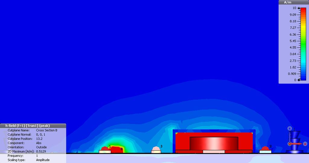
40 H-Field, 1 MHz, Side View Magnetically Shielded
41 Unshielded, Ez 1cm above PCB


42 Unshielded, Ez 1cm above PCB

43 E-field, 1 MHz, Side View
44 No Shielding

45 Magnetic Shield over Inductor

46 Electric Shield over Inductor only

47 Electric Shield over Inductor + SW Node
48 Near Field Coupling Noise coupling phenomena below 30 MHz (deep in Near-Field Zone) with vehicle antenna is via E and H fields. E and H fields coexist at all times regardless of noise source impedance as seen here. Electric Field Source Magnetic Field Source H-Field Shielded Inductor + using low inductance capacitor and practicing best EMI guidelines, i.e., reduction of mounting inductance is NOT sufficient. L1 and SW node trace MUST be shielded using a conductive material (i.e., copper) and bonded to PCB Ground.
49 Summary SMPS EMI is a real problem, especially for automotive (ever more complex electromagnetic environment) Time domain measurements revealed higher frequency noise, near field probes revealed AM Band noise two different effects (E and H fields) Shielding of inductor and large switch node trace proven to reduce emissions may not be an option Must take care with PCB layout and consider high dv/dt of Switch Node Validation and verification of experimental findings with CEM simulation software

50 Thank you! Any questions?
CST s Simulation Capabilities for Automotive Applications. An Overview Dr. Matthias Tröscher
 CST s Simulation Capabilities for Automotive Applications An Overview Dr. Matthias Tröscher CST Asian Automotive Workshop Seongnam, Korea - November 2014 CST European Automotive Workshop BMW World, Munich,
Understanding and Optimizing Electromagnetic Compatibility in Switchmode Power Supplies
 Understanding and Optimizing Electromagnetic Compatibility in Switchmode Power Supplies 1 Definitions EMI = Electro Magnetic Interference EMC = Electro Magnetic Compatibility (No EMI) Three Components
Course Introduction. Content 16 pages. Learning Time 30 minutes
 Course Introduction Purpose This course discusses techniques for analyzing and eliminating noise in microcontroller (MCU) and microprocessor (MPU) based embedded systems. Objectives Learn what EMI is and
IEEE RTPGE Automotive Datalinks over Twisted Quad Cabling
 Automotive Datalinks over Twisted Quad Cabling T. Müller, G. Armbrecht, S. Kunz Rosenberger Hochfrequenztechnik GmbH & Co. KG Outline Automotive Datalinks over Twisted Quad Cabling Twisted Quad fundamentals
Electromagnetic Compatibility
 Electromagnetic Compatibility Introduction to EMC International Standards Measurement Setups Emissions Applications for Switch-Mode Power Supplies Filters 1 What is EMC? A system is electromagnetic compatible
ELEC 0017: ELECTROMAGNETIC COMPATIBILITY LABORATORY SESSIONS
 Academic Year 2015-2016 ELEC 0017: ELECTROMAGNETIC COMPATIBILITY LABORATORY SESSIONS V. BEAUVOIS P. BEERTEN C. GEUZAINE 1 CONTENTS: EMC laboratory session 1: EMC tests of a commercial Christmas LED light
Debugging EMI Using a Digital Oscilloscope. Dave Rishavy Product Manager - Oscilloscopes
 Debugging EMI Using a Digital Oscilloscope Dave Rishavy Product Manager - Oscilloscopes 06/2009 Nov 2010 Fundamentals Scope Seminar of DSOs Signal Fidelity 1 1 1 Debugging EMI Using a Digital Oscilloscope
Solution of EMI Problems from Operation of Variable-Frequency Drives
 Pacific Gas and Electric Company Solution of EMI Problems from Operation of Variable-Frequency Drives Background Abrupt voltage transitions on the output terminals of a variable-frequency drive (VFD) are
Ileana-Diana Nicolae ICMET CRAIOVA UNIVERSITY OF CRAIOVA MAIN BUILDING FACULTY OF ELECTROTECHNICS
 The Designing, Realization and Testing of a Network Filter used to Reduce Electromagnetic Disturbances and to Improve the EMI for Static Switching Equipment Petre-Marian Nicolae Ileana-Diana Nicolae George
Class-D Audio Power Amplifiers: PCB Layout For Audio Quality, EMC & Thermal Success (Home Entertainment Devices)
") Class-D Audio Power Amplifiers: PCB Layout For Audio Quality, EMC & Thermal Success (Home Entertainment Devices) Stephen Crump http://e2e.ti.com Audio Power Amplifier Applications Audio and Imaging Products
Class-D Audio Power Amplifiers: PCB Layout For Audio Quality, EMC & Thermal Success (Home Entertainment Devices) Stephen Crump http://e2e.ti.com Audio Power Amplifier Applications Audio and Imaging Products
Development of a noval Switched Beam Antenna for Communications
 Master Thesis Presentation Development of a noval Switched Beam Antenna for Communications By Ashraf Abuelhaija Supervised by Prof. Dr.-Ing. Klaus Solbach Institute of Microwave and RF Technology Department
Heat sink. Insulator. µp Package. Heatsink is shown with parasitic coupling.
 X2Y Heatsink EMI Reduction Solution Summary Many OEM s have EMI problems caused by fast switching gates of IC devices. For end products sold to consumers, products must meet FCC Class B regulations for
FUNDAMENTALS OF EMC. Candace Suriano John Suriano
 FUNDAMENTALS OF EMC Candace Suriano John Suriano Special Thanks to our Sponsor Helpful books on EMC Helpful books on Signals Much of our material can be found in these articles Articles: Candace Suriano,
150Hz to 1MHz magnetic field coupling to a typical shielded cable above a ground plane configuration
 150Hz to 1MHz magnetic field coupling to a typical shielded cable above a ground plane configuration D. A. Weston Lowfreqcablecoupling.doc 7-9-2005 The data and information contained within this report
Test and Measurement for EMC
 Test and Measurement for EMC Bogdan Adamczyk, Ph.D., in.c.e. Professor of Engineering Director of the Electromagnetic Compatibility Center Grand Valley State University, Michigan, USA Ottawa, Canada July
Todd Hubing. Clemson University. Cabin Environment Communication System. Controls Airbag Entertainment Systems Deployment
 Automotive Component Measurements for Determining Vehicle-Level Radiated Emissions Todd Hubing Michelin Professor of Vehicular Electronics Clemson University Automobiles are Complex Electronic Systems
Chapter 16 PCB Layout and Stackup
 Chapter 16 PCB Layout and Stackup Electromagnetic Compatibility Engineering by Henry W. Ott Foreword The PCB represents the physical implementation of the schematic. The proper design and layout of a printed
Categorized by the type of core on which inductors are wound:
 Inductors Categorized by the type of core on which inductors are wound: air core and magnetic core. The magnetic core inductors can be subdivided depending on whether the core is open or closed. Equivalent
Reducing EMI in buck converters
 Application Note Roland van Roy AN045 January 2016 Reducing EMI in buck converters Abstract Reducing Electromagnetic interference (EMI) in switch mode power supplies can be a challenge, because of the
Todd H. Hubing Michelin Professor of Vehicular Electronics Clemson University
 Essential New Tools for EMC Diagnostics and Testing Todd H. Hubing Michelin Professor of Vehicular Electronics Clemson University Where is Clemson University? Clemson, South Carolina, USA Santa Clara Valley
Electromagnetic Simulation of Antennas Installed Inside Vehicles An Automotive EMC Approach Markus Kopp Product Manager, Electronics
 Electromagnetic Simulation of Antennas Installed Inside Vehicles An Automotive EMC Approach Markus Kopp Product Manager, Electronics 1 Automotive Antenna Systems and Automotive EMC Recent technology implementations
Investigation of a Voltage Probe in Microstrip Technology
 Investigation of a Voltage Probe in Microstrip Technology (Specifically in 7-tesla MRI System) By : Mona ParsaMoghadam Supervisor : Prof. Dr. Ing- Klaus Solbach April 2015 Introduction - Thesis work scope
How EMxpert Diagnoses Board-Level EMC Design Issues
 Application Report EMxpert July 2011 - Cédric Caudron How EMxpert Diagnoses Board-Level EMC Design Issues ABSTRACT EMxpert provides board-level design teams with world-leading fast magnetic very-near-field
Application Note 0006
 VGS Transient Tolerance of Transphorm GaN FETs Abstract This document provides a guideline for allowable transient voltages between gate and source pins. Table of Contents Abstract... 1 Introduction...
EMC simulation addresses ECU validation issues
 EMC simulation addresses ECU validation issues A more straightforward validation of electromagnetic compatibility can be achieved by combining tools. By Stefan Heimburger, Andreas Barchanski, and Thorsten
EMC Simulation of Consumer Electronic Devices
 of Consumer Electronic Devices By Andreas Barchanski Describing a workflow for the EMC simulation of a wireless router, using techniques that can be applied to a wide range of consumer electronic devices.
11 Myths of EMI/EMC ORBEL.COM. Exploring common misconceptions and clarifying them. MYTH #1: EMI/EMC is black magic.
 11 Myths of EMI/EMC Exploring common misconceptions and clarifying them By Ed Nakauchi, Technical Consultant, Orbel Corporation What is a myth? A myth is defined as a popular belief or tradition that has
Chapter 12 Digital Circuit Radiation. Electromagnetic Compatibility Engineering. by Henry W. Ott
 Chapter 12 Digital Circuit Radiation Electromagnetic Compatibility Engineering by Henry W. Ott Forward Emission control should be treated as a design problem from the start, it should receive the necessary
Techniques to reduce electromagnetic noise produced by wired electronic devices
 Rok / Year: Svazek / Volume: Číslo / Number: Jazyk / Language 2016 18 5 EN Techniques to reduce electromagnetic noise produced by wired electronic devices - Tomáš Chvátal xchvat02@stud.feec.vutbr.cz Faculty
Analogue circuit design for RF immunity
 Analogue circuit design for RF immunity By EurIng Keith Armstrong, C.Eng, FIET, SMIEEE, www.cherryclough.com First published in The EMC Journal, Issue 84, September 2009, pp 28-32, www.theemcjournal.com
CHAPTER 2 EQUIVALENT CIRCUIT MODELING OF CONDUCTED EMI BASED ON NOISE SOURCES AND IMPEDANCES
 29 CHAPTER 2 EQUIVALENT CIRCUIT MODELING OF CONDUCTED EMI BASED ON NOISE SOURCES AND IMPEDANCES A simple equivalent circuit modeling approach to describe Conducted EMI coupling system for the SPC is described
Design for Guaranteed EMC Compliance
 Clemson Vehicular Electronics Laboratory Reliable Automotive Electronics Automotive EMC Workshop April 29, 2013 Design for Guaranteed EMC Compliance Todd Hubing Clemson University EMC Requirements and
Differential-Mode Emissions
 Differential-Mode Emissions In Fig. 13-5, the primary purpose of the capacitor C F, however, is to filter the full-wave rectified ac line voltage. The filter capacitor is therefore a large-value, high-voltage
Understanding, measuring, and reducing output noise in DC/DC switching regulators
 Understanding, measuring, and reducing output noise in DC/DC switching regulators Practical tips for output noise reduction Katelyn Wiggenhorn, Applications Engineer, Buck Switching Regulators Robert Blattner,
Design of EMI Filters for DC-DC converter
 Design of EMI Filters for DC-DC converter J. L. Kotny*, T. Duquesne**, N. Idir** Univ. Lille Nord de France, F-59000 Lille, France * USTL, F-59650 Villeneuve d Ascq, France ** USTL, L2EP, F-59650 Villeneuve
Modeling and Simulation of Powertrains for Electric and Hybrid Vehicles
 Modeling and Simulation of Powertrains for Electric and Hybrid Vehicles Dr. Marco KLINGLER PSA Peugeot Citroën Vélizy-Villacoublay, FRANCE marco.klingler@mpsa.com FR-AM-5 Background The automotive context
The Engineer s Guide To EMI In DC-DC Converters (Part 5): Mitigation Techniques Using Integrated FET Designs
: Mitigation Techniques Using Integrated FET Designs") ISSUE: June 2018 The Engineer s Guide To EMI In DC-DC Converters (Part 5): Mitigation Techniques Using Integrated FET Designs by Timothy Hegarty, Texas Instruments, Phoenix, Ariz. Parts 1 through 4 of
ISSUE: June 2018 The Engineer s Guide To EMI In DC-DC Converters (Part 5): Mitigation Techniques Using Integrated FET Designs by Timothy Hegarty, Texas Instruments, Phoenix, Ariz. Parts 1 through 4 of
EMC cases study. Antonio Ciccomancini Scogna, CST of America CST COMPUTER SIMULATION TECHNOLOGY
 EMC cases study Antonio Ciccomancini Scogna, CST of America antonio.ciccomancini@cst.com Introduction Legal Compliance with EMC Standards without compliance products can not be released to the market Failure
Common myths, fallacies and misconceptions in Electromagnetic Compatibility and their correction.
 Common myths, fallacies and misconceptions in Electromagnetic Compatibility and their correction. D. A. Weston EMC Consulting Inc 22-3-2010 These are some of the commonly held beliefs about EMC which are
433MHz front-end with the SA601 or SA620
 433MHz front-end with the SA60 or SA620 AN9502 Author: Rob Bouwer ABSTRACT Although designed for GHz, the SA60 and SA620 can also be used in the 433MHz ISM band. The SA60 performs amplification of the
Verifying Simulation Results with Measurements. Scott Piper General Motors
 Verifying Simulation Results with Measurements Scott Piper General Motors EM Simulation Software Can be easy to justify the purchase of software packages even costing tens of thousands of dollars Upper
3250 Series Spectrum Analyzer
 The most important thing we build is trust ADVANCED ELECTRONIC SOLUTIONS AVIATION SERVICES COMMUNICATIONS AND CONNECTIVITY MISSION SYSTEMS 3250 Series Spectrum Analyzer > Agenda Introduction
New dimensions for multifunctional car keys
 Technologies & Products Press Conference 2018 New dimensions for multifunctional car keys 4D transponder coil with integrated NFC or wireless charging coils Leopoldo Bertossi Product Marketing Director
EM Noise Mitigation in Electronic Circuit Boards and Enclosures
 EM Noise Mitigation in Electronic Circuit Boards and Enclosures Omar M. Ramahi, Lin Li, Xin Wu, Vijaya Chebolu, Vinay Subramanian, Telesphor Kamgaing, Tom Antonsen, Ed Ott, and Steve Anlage A. James Clark
1.5MHz, 1A Synchronous Step-Down Regulator
 1.5MHz, 1A Synchronous Step-Down Regulator FP6161 General Description The FP6161 is a high efficiency current mode synchronous buck PWM DC-DC regulator. The internal generated 0.6V precision feedback reference
PCB Design Guidelines for Reduced EMI
 PCB Design Guidelines for Reduced EMI Guided By: Prof. Ruchi Gajjar Prepared By: Shukla Jay (13MECE17) Outline Power Distribution for Two-Layer Boards Gridding Power Traces on Two-Layer Boards Ferrite
Qualified for industrial applications according to the relevant tests of JEDEC47/20/22.
 Product description The is a wideband NPN RF heterojunction bipolar transistor (HBT). Feature list Low noise figure NF min = 1 db at 5.5 GHz, 3 V, 6 ma High gain G ms = 21 db at 5.5 GHz, 3 V, 15 ma OIP
Overview of EMC Regulations and Testing. Prof. Tzong-Lin Wu Department of Electrical Engineering National Taiwan University
 Overview of EMC Regulations and Testing Prof. Tzong-Lin Wu Department of Electrical Engineering National Taiwan University What is EMC Electro-Magnetic Compatibility ( 電磁相容 ) EMC EMI (Interference) Conducted
Course Introduction Purpose Objectives Content Learning Time
 Course Introduction Purpose This course discusses techniques for analyzing and eliminating noise in microcontroller (MCU) and microprocessor (MPU) based embedded systems. Objectives Learn about a method
Wide Band-Gap (SiC and GaN) Devices Characteristics and Applications. Richard McMahon University of Cambridge
 Devices Characteristics and Applications. Richard McMahon University of Cambridge") Wide Band-Gap (SiC and GaN) Devices Characteristics and Applications Richard McMahon University of Cambridge Wide band-gap power devices SiC : MOSFET JFET Schottky Diodes Unipolar BJT? Bipolar GaN : FET
Wide Band-Gap (SiC and GaN) Devices Characteristics and Applications Richard McMahon University of Cambridge Wide band-gap power devices SiC : MOSFET JFET Schottky Diodes Unipolar BJT? Bipolar GaN : FET
NUMERICAL METHODOLOGY FOR THE EMI RISK ASSESSMENT OF VEHICULAR ANTENNAS
 NUMERICAL METHODOLOGY FOR THE EMI RISK ASSESSMENT OF VEHICULAR ANTENNAS Alberto Buttiglieri EMEA Product Development Electrical Electronics Unit Audio & Telematics Darmstadt, Germany Content Automotive
Suppression Techniques using X2Y as a Broadband EMI Filter IEEE International Symposium on EMC, Boston, MA
 Suppression Techniques using X2Y as a Broadband EMI Filter Jim Muccioli Tony Anthony Dave Anthony Dale Sanders X2Y Attenuators, LLC Erie, PA 16506-2972 www.x2y.com Email: x2y@x2y.com Bart Bouma Yageo/Phycomp
APPLICATION NOTE. System Design for RF Immunity
 APPLICATION NOTE System Design for RF Immunity Audio Codec Application Note Rev1.0 Page 1 of 6 March 2008 With the growth of the portable electronic devices industry, radiated RF fields and potential interference
1 Introduction. Webinar sponsored by: Cost-effective uses of close-field probing. Contents
 1of 8 Close-field probing series Webinar #1 of 2, Cost-effective uses of close-field probing in every project stage: emissions, immunity and much more Webinar sponsored by: Keith Armstrong CEng, EurIng,
4. THEORETICAL: EMISSION AND SUSCEPTIBILITY. pressure sensor, i.e, via printed-circuit board tracks, internal wiring which acts as an
 4. THEORETICAL: EMISSION AND SUSCEPTIBILITY There are many ways for the electromagnetic-interference to be coupled to the pressure sensor, i.e, via printed-circuit board tracks, internal wiring which acts
Conducted EMI Simulation of Switched Mode Power Supply
 Conducted EMI Simulation of Switched Mode Power Supply Hongyu Li #1, David Pommerenke #2, Weifeng Pan #3, Shuai Xu *4, Huasheng Ren *5, Fantao Meng *6, Xinghai Zhang *7 # EMC Laboratory, Missouri University
Testing for EMC Compliance: Approaches and Techniques October 12, 2006
 : Approaches and Techniques October 12, 2006 Ed Nakauchi EMI/EMC/ESD/EMP Consultant Emulex Corporation 1 Outline Discuss EMC Basics & Physics Fault Isolation Techniques Tools & Techniques Correlation Analyzer
Chapter 5 Electromagnetic interference in flash lamp pumped laser systems
 Chapter 5 Electromagnetic interference in flash lamp pumped laser systems This chapter presents the analysis and measurements of radiated near and far fields, and conducted emissions due to interconnects
Leading antenna solution provider
 Challenging the world with advanced material products Leading antenna solution provider The Most Reliable Antenna Copyright c 2010 Amotech corp. All right reserved. GPS GPS Antenna Ceramic patch-pin type
EMI. Chris Herrick. Applications Engineer
 Fundamentals of EMI Chris Herrick Ansoft Applications Engineer Three Basic Elements of EMC Conduction Coupling process EMI source Emission Space & Field Conductive Capacitive Inductive Radiative Low, Middle
The Causes and Impact of EMI in Power Systems; Part 1. Chris Swartz
 The Causes and Impact of EMI in Power Systems; Part Chris Swartz Agenda Welcome and thank you for attending. Today I hope I can provide a overall better understanding of the origin of conducted EMI in
TECHNICAL REPORT: CVEL EMI Source Modeling of the John Deere CA6 Motor Driver. C. Zhu, A. McDowell and T. Hubing Clemson University
 TECHNICAL REPORT: CVEL-11-029 EMI Source Modeling of the John Deere CA6 Motor Driver C. Zhu, A. McDowell and T. Hubing Clemson University October 1, 2011 Table of Contents Executive Summary... 3 1. Introduction...
LM2462 Monolithic Triple 3 ns CRT Driver
 LM2462 Monolithic Triple 3 ns CRT Driver General Description The LM2462 is an integrated high voltage CRT driver circuit designed for use in color monitor applications. The IC contains three high input
Qualified for industrial applications according to the relevant tests of JEDEC47/20/22.
 Product description The BFP7 is a wideband NPN RF heterojunction bipolar transistor (HBT). Feature list Low noise figure NF min =.8 db at. GHz, 3 V, 6 ma High gain G ms = 9. db at. GHz, 3 V, ma OIP 3 =.
EMI/EMC of Entire Automotive Vehicles and Critical PCB s. Makoto Suzuki Ansoft Corporation
 EMI/EMC of Entire Automotive Vehicles and Critical PCB s Makoto Suzuki Ansoft Corporation WT10_SI EMI/EMC of Entire Automotive Vehicles and Critical PCB s Akira Ohta, Toru Watanabe, Benson Wei Makoto Suzuki
ROD ANTENNA TESTING Complete article download from: EMI TESTING. Basic RE102 test (2-30 MHz)
") ROD ANTENNA TESTING Complete article download from: http://stevejensenconsultants.com/rod_ant.pdf EMI TESTING Steve Jensen Steve Jensen Consultants Inc. Sept. 26, 2005 Applicable for DO-160 sec. 21 and
ROD ANTENNA TESTING Complete article download from: http://stevejensenconsultants.com/rod_ant.pdf EMI TESTING Steve Jensen Steve Jensen Consultants Inc. Sept. 26, 2005 Applicable for DO-160 sec. 21 and
Qualified for industrial applications according to the relevant tests of JEDEC47/20/22.
 Product description The BFP8ESD is a high performance RF heterojunction bipolar transistor (HBT) with an integrated ESD protection suitable for. -. GHz LNA applications. Feature list Unique combination
AltiumLive 2017: Component selection for EMC
 AltiumLive 2017: Component selection for EMC Martin O Hara Victory Lighting Ltd Munich, 24-25 October 2017 Component Selection Passives resistors, capacitors and inductors Discrete diodes, bipolar transistors,
Wireless Power Transfer. CST COMPUTER SIMULATION TECHNOLOGY
 Wireless Power Transfer Some History 1899 - Tesla 1963 - Schuder 1964 - Brown from Garnica et al. (2013) from Schuder et al. (1963) from Brown (1964) Commercialization 1990s onward: mobile device charging
QPI-AN1 GENERAL APPLICATION NOTE QPI FAMILY BUS SUPPLY QPI CONVERTER
 QPI-AN1 GENERAL APPLICATION NOTE QPI FAMILY EMI control is a complex design task that is highly dependent on many design elements. Like passive filters, active filters for conducted noise require careful
Unclassified Distribution A: Unlimited Public Release
 IMPACT OF INADVERTENT ELECTROMAGNETIC EMISSIONS ON ORGANIC VEHICLES THAT AFFECT THE TACTICAL COMMUNICATIONS OPERATING BANDS By Erick Ortiz and Frank A. Bohn US ARMY CERDEC Antennas & Spectrum Analysis
1.5MHz, 600mA Synchronous Step-Down Regulator
 1.5MHz, 600mA Synchronous Step-Down Regulator FP6160B General Description The FP6160B is a high efficiency current mode synchronous buck PWM DC-DC regulator. The internal generated 0.6V precision feedback
Electronics Centre in Halmstad ECH
 Electronics Centre in Halmstad ECH About Electronics Centre in Halmstad ECH Electronics Centre in Halmstad (ECH) is a strategic effort created by Halmstad University in collaboration with regional companies
DF Antennas - Datasheet. Datasheet
 DF Antennas - Datasheet Datasheet To cover a wide frequency range with high sensitivity, Narda offers several directional antennas. Each antenna is optimized for their particular frequency range with regard
Smart Energy Solutions for the Wireless Home
 Smart Energy Solutions for the Wireless Home Advanced Metering Infrastructure (AMI) ZigBee (IEEE 802.15.4) Wireless Local Area Networks (WLAN) Industrial and Home Control Plug-in Hybrid Electric Vehicles
CORRELATION CAR BODY-ANTENNA, FOR GOOD RECEPTION IN COMMUNICATIONS AND ENTERTAINMENT
 CORRELATION CAR BODY-ANTENNA, FOR GOOD RECEPTION IN COMMUNICATIONS AND ENTERTAINMENT Valeriu Enache Transilvania University of Brasov, Romania KEYWORDS car antenna, corelation antenna, car body ABSTRACT
A Novel Embedded Common-mode Filter for above GHz differential signals based on Metamaterial concept. Tzong-Lin Wu
 c //3 A Novel Embedded Common-mode Filter for above GHz differential signals based on Metamaterial concept Tzong-Lin Wu Professor Graduate Institute of Communication Engineering, National Taiwan University,
Progress In Electromagnetics Research, Vol. 119, , 2011
 Progress In Electromagnetics Research, Vol. 119, 253 263, 2011 A VALIDATION OF CONVENTIONAL PROTECTION DEVICES IN PROTECTING EMP THREATS S. M. Han 1, *, C. S. Huh 1, and J. S. Choi 2 1 INHA University,
tuning and RF circuits wireless automotive inductors inductance (L). Now frequencies
. Now frequencies") RF Chip Inductor Applications December 2011 Application Note RF chip are an integral part of many tuning and filtering circuits and are mainly used in the RF circuits in electronics systems. With a small
RF Chip Inductor Applications December 2011 Application Note RF chip are an integral part of many tuning and filtering circuits and are mainly used in the RF circuits in electronics systems. With a small
The Impact Of Signal Jumping Across Multiple Different Reference Planes On Electromagnetic Compatibility
 Copyright by Dr. Andrew David Norte, All Rights Reserved March 18 th, 2012 The Impact Of Signal Jumping Across Multiple Different Reference Planes On Electromagnetic Compatibility David Norte, PhD www.the-signal-and-power-integrity-institute.com
T + T /13/$ IEEE 236. the inverter s input impedances on the attenuation of a firstorder
 Emulation of Conducted Emissions of an Automotive Inverter for Filter Development in HV Networks M. Reuter *, T. Friedl, S. Tenbohlen, W. Köhler Institute of Power Transmission and High Voltage Technology
SN W Mono Filterless Class-D Audio Power Amplifier DESCRIPTION FEATURES APPLICATIONS. Typical Application Circuit
 2.6W Mono Filterless Class-D Audio Power Amplifier DESCRIPTION The SN200 is a 2.6W high efficiency filter-free class-d audio power amplifier in a.5 mm.5 mm wafer chip scale package (WCSP) that requires
Introduction to Electromagnetic Compatibility
 Introduction to Electromagnetic Compatibility Second Edition CLAYTON R. PAUL Department of Electrical and Computer Engineering, School of Engineering, Mercer University, Macon, Georgia and Emeritus Professor
1.5MHz, 3A Synchronous Step-Down Regulator
 1.5MHz, 3A Synchronous Step-Down Regulator FP6165 General Description The FP6165 is a high efficiency current mode synchronous buck PWM DC-DC regulator. The internal generated 0.6V precision feedback reference
EMC review for Belle II (Grounding & shielding plans) PXD DEPFET system
 PXD DEPFET system") EMC review for Belle II (Grounding & shielding plans) PXD DEPFET system Outline 1. Introduction 2. Grounding strategy Implementation aspects 3. Noise emission issues Test plans 4. Noise immunity issues
EMC review for Belle II (Grounding & shielding plans) PXD DEPFET system Outline 1. Introduction 2. Grounding strategy Implementation aspects 3. Noise emission issues Test plans 4. Noise immunity issues
OnBoard SMD WLAN antenna
 Application note and implementation guideline OnBoard SMD WLAN antenna Patent: SE537042 + Pending rev 1.2 Proant AB 1 Table of contents 1. General... 3 2. Intended applications... 3 3. Technical data...
1.5MHz, 800mA Synchronous Step-Down Regulator
 1.5MHz, 800mA Synchronous Step-Down Regulator General Description The is a high efficiency current mode synchronous buck PWM DC-DC regulator. The internal generated 0.6V precision feedback reference voltage
1.5MHz, 2A Synchronous Step-Down Regulator
 1.5MHz, 2A Synchronous Step-Down Regulator General Description The is a high efficiency current mode synchronous buck PWM DC-DC regulator. The internal generated 0.6V precision feedback reference voltage
OnBoard SMD WLAN antenna
 Page 1 Rev 1.6 Application note and implementation guideline OnBoard SMD WLAN antenna Patent: SE537042 + Pending Page 2 Rev 1.6 Table of contents 1. General... 3 2. Intended applications... 3 3. Technical
GaN Transistors for Efficient Power Conversion
 GaN Transistors for Efficient Power Conversion Agenda How GaN works Electrical Characteristics Design Basics Design Examples Summary 2 2 How GaN Works 3 3 The Ideal Power Switch Block Infinite Voltage
Probing challenges when testing WBG devices power-conference.com/
 Probing challenges when testing WBG devices power-conference.com/ Andrea Vinci Business Development EMEA Automotive &Power Solutions Tektronix: supporting humankind's greatest advances and future vision
LM V Monolithic Triple Channel 15 MHz CRT DTV Driver
 220V Monolithic Triple Channel 15 MHz CRT DTV Driver General Description The is a triple channel high voltage CRT driver circuit designed for use in DTV applications. The IC contains three high input impedance,
The shunt capacitor is the critical element
 Accurate Feedthrough Capacitor Measurements at High Frequencies Critical for Component Evaluation and High Current Design A shielded measurement chamber allows accurate assessment and modeling of low pass
RF Energy Harvesting for Low Power Electronic Devices
 RF Energy Harvesting for Low Power Electronic Devices Student project Kaloyan A. Mihaylov Abstract Different methods for RF energy harvesting from radio transmitters with working frequency of up to 108
EMC TEST REPORT - Addendum
 PRODUCT SAFETY AND COMPLIANCE EMC LABORATORY EMC TEST REPORT - Addendum Test Report Number 24262-1 WLAN Report Date 2010-12-08 The test results contained herein relate only to the model(s) identified.
Becker Nachrichtentechnik GmbH Kapellenweg Asbach - Germany
 High Dynamic 8 Way Combiner 100 khz... 4000 MHz, 50 Ω Features - wideband - high dynamic - without signal losses - low power consumption - high port- to- port isolation - compact 19, 1 U design Applications
V1.3. TBLC08 50mH AC-LISN TBLC08
 V1.3 TBLC08 The TBLC08 is a Line Impedance Stabilization Network for the measurement of line-conducted interference within the range of 9kHz to 30MHz, according to the CISPR16 standard. The device is designed
WD3122EC. Descriptions. Features. Applications. Order information. High Efficiency, 28 LEDS White LED Driver. Product specification
 High Efficiency, 28 LEDS White LED Driver Descriptions The is a constant current, high efficiency LED driver. Internal MOSFET can drive up to 10 white LEDs in series and 3S9P LEDs with minimum 1.1A current
Electromagnetic Compliance: Pre-Compliance Test Basics October 19, 2017
 Electromagnetic Compliance: Pre-Compliance Test Basics October 19, 2017 Today s products are subjected to more standardized test requirements than ever before. These standards (UL, CE, and others) ensure
Controlling Input Ripple and Noise in Buck Converters
 Controlling Input Ripple and Noise in Buck Converters Using Basic Filtering Techniques, Designers Can Attenuate These Characteristics and Maximize Performance By Charles Coles, Advanced Analogic Technologies,