LISN UP Application Note
|
|
|
- Cynthia Walton
- 6 years ago
- Views:
Transcription
1 LISN UP Application Note What is the LISN UP? The LISN UP is a passive device that enables the EMC Engineer to easily distinguish between differential mode noise and common mode noise. This will enable efficient troubleshooting of power line EMI filters shortcomings and allow the EMC Engineer to focus on the dominant mode noise performance. Once the dominant mode is determined, the filter components associated with the dominant mode can be identified. Identification of the offending filter components will focus efforts rather than the expensive trial and error random component change and retest cycle. The LISN UP is connected to the output ports of either a dual line LISN or two identical single line LISNs. Care must be taken to make sure the interconnecting cables are identical in length and construction and have good RF shielding effectiveness. The output of the LISN UP can be switched between the common mode component and the differential mode component by a manual two position switch without changing any external RF connections. How Does It Work? First, we need to review some of the theory so we can start from a common understanding of noise voltage modes. In a typical circuit, conventional current flows from the positive voltage terminal to the load and it eventually returns to the negative terminal of the voltage source as shown in Figure 1. This is differential mode current. The current flowing into the load is equal to the current flowing out of the load and back to the source. The only difference is the phase between these two currents. They differ by 180 o and ideally they would cancel out. Common mode currents flow on each lead and return on the ground plane or green wire safety ground. The amplitude and phase of these currents are the same on both conductors. A diagram of this is shown in Figure 2. Putting these two concepts together and examining the current flows we find that the net current on any of the conductors is algebraic sum of the differential mode current and the common mode current. The current returning via the green wire ground is the sum of the common mode currents or twice the common mode current of any one of the conductors. This is illustrated in Figure 3. Knowledge of these characteristics will be used to our advantage when we need to determine whether the voltages are common mode or differential mode. 1
2 Since we know the equations to describe the current in each conductor we can perform mathematical operations to separate the differential mode and common mode components. The equations are listed below: I a = I cm + I dm I b = I cm - I dm These currents flow across the impedance of the LISN which give us a corresponding noise voltage to measure. The noise voltage for each conductor can be described as follows: V a = (I cm + I dm) * Z lisn V b = (I cm - I dm) * Z lisn If we sum V a and V b together, ideally we will obtain twice the common mode voltage component and the differential mode component will cancel. This means that if we had equal common voltage magnitudes on both conductors and they had the exact same phase we would get twice the voltage or 6 db higher than the magnitude of either line. This is illustrated in Figure 4. the differential mode component is added. We ideally get twice the differential mode component. This means that if we had equal differential mode voltage magnitudes on both conductors and they had the exact same phase we would get twice the voltage or 6 db higher than the magnitude of either line. This is How Do I Set It Up? The LISN UP is designed to be used with either a dual LISN or two individual LISNS. The unit under test is connected to the power supply and LISN the same way it has always connected. The differences are the connections between the 50 ohm measurement ports and the EMI Receiver or spectrum analyzer. Each RF measurement port on the LISN is attached to the LISN UP input ports. The LISN UP Output port is connected to the measurement receiver. The RF output is switched between common mode and differential mode. Typical connections are shown in Figure 6. The coaxial cables between the LISN RF output ports and the LISN UP Input ports must be identical to maintain the performance of the LISN UP. The cables must be of identical length, shielding quality and characteristic impedance. If adapters are used they too must be identical. To separate out the differential mode voltage an additional operation must be performed. One of the inputs to the summing junction must have the phase inverted 180 o prior to summing the two voltage signals together. When the two signals are summed together the common mode component is ideally canceled and 2 How Do I Use It? The LISN UP is relatively simple to use if you have performed conducted voltage emissions tests, and have an understanding of the fundamentals of common mode, differential mode, and filtering. Typically, in the past, conducted voltage emissions were performed and the equipment under test passed or failed. If it failed you ended up in a try a fix and repeat the measurement scenario. Depending on your experience and luck you may have fixed the problem in a few hours or weeks. The LISN UP will help you focus on the dominant noise mode for those out of specification conditions rather than blindly changing components in the hope it fixes the problem. You may have a common
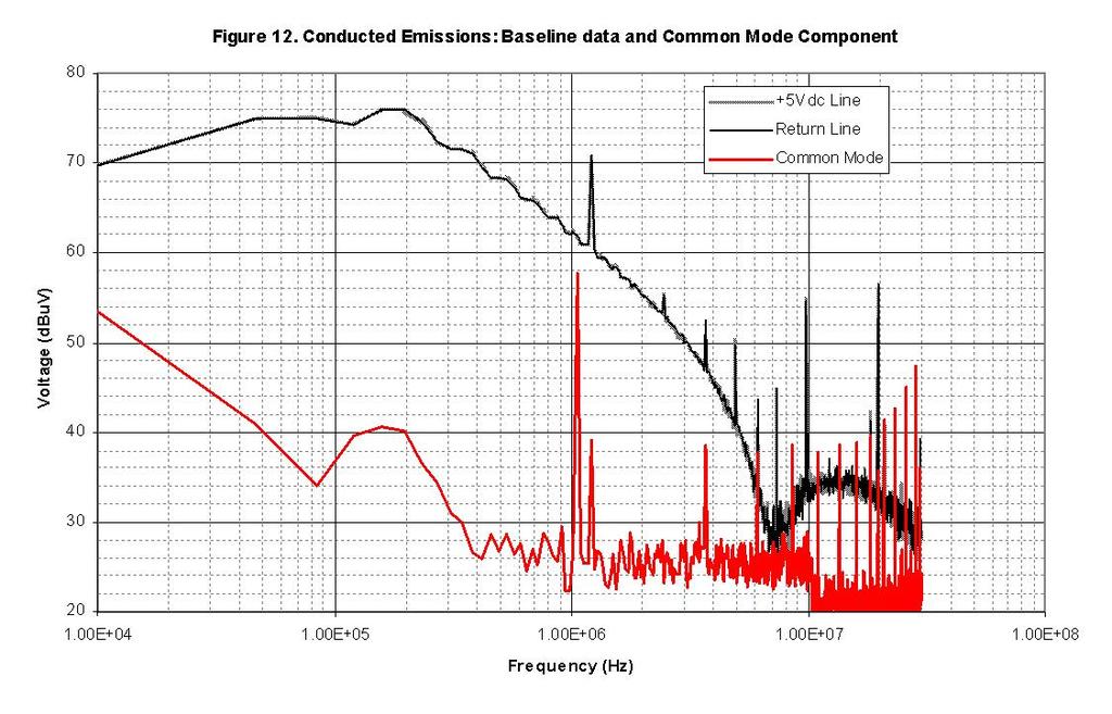
3 mode problem yet you decide to change a differential mode filter component. You repeat the measurement on both lines and you find there is no difference in the performance. Had you known that the common mode component was dominant you would have chosen to add a common mode component or modify the existing common mode component. This would have saved you valuable time! A generic procedure for troubleshooting your input EMI filter out of compliance conditions is outlined below. GENERIC PROCEDURE The RF conducted voltage emissions for each power line is generally measured first to determine compliance to the applicable regulatory specification. If there are non-compliances, the LISN UP is used to determine the dominant modes of conducted noise voltage. The dominant mode at each frequency of noncompliance needs to be characterized to efficiently troubleshoot and modify the EMI filter. This is accomplished using the test procedure below: Step 1. Measure the conducted voltage emissions for each line under test using the required LISNs. Step 2. Note any non-compliant voltage emissions conditions Record each non-compliant frequency, amplitude and the offending line. Step 3. Connect the LISN UP to the dual LISN or (2) single LISNs. This is accomplished by connecting the LISN RF Output Ports to the RF Input Ports of the LISN UP. Connect the measurement receiver to the RF output of the LISN UP. See Figure 6. Step 4. Power up the equipment under test. Step 5. With the LISN-UP RF Output Switch in the Differential Mode position and measure the conducted voltage emissions at the first non-compliant frequency. Step 6. Record the frequency and amplitude for the Differential Mode measurement. Step 7. Position the LISN-UP RF Output Switch to the Com mon mode position and measure the conducted voltage emission at this frequency. Step 8. Compare the relative amplitudes of the Common Mode component and the Differential Mode component of the conducted noise voltage. If either component is signifcantly larger than the other, that is the dominant mode. There will be cases where the amplitudes are of similar magnitudes for both components. In this case, there is both common mode and differential mode noise present and no one mode dominates. Step 9. Repeat this for each non-compliant frequency until all have been identified. Step 10. Depending on which mode(s) are dominant the filter components that need to be changed can easily be identified. Step 11. After the EMI filter has been modified repeat steps 1 and 2. 3 Step 12. If the equipment under test is still out of compliance repeat steps 3 to 11 until the EMI Filter meets the applicable specification. Which Filter Components Are Differential Mode or Common Mode? Differential mode filter components are usually the components that are either: line to line capacitors, series inductors and sometimes leakage inductance from a common mode choke. Common mode components are line to chassis capacitors and common mode chokes. A generic EMI filter diagram is shown in Figure 7 and the components are labeled differential mode or common mode. The differential mode components are labeled with a dm subscript and the common mode components are labeled with the cm subscript. Example Problem A simple conducted noise source and EMI Filter were designed and constructed to demonstrate how the LISN UP is used. This will help the user better understand how the LISN UP works, what to expect and how to interpret the data. A diagram of the test setup is shown in Figure 8. We will use the generic procedure as a guide. Step 1. We measured the conducted voltage emissions of the +5Vdc line and the power Return line. This is shown in Figure 9. Step 2. We find that the conducted voltage emission levels are higher than 40 dbuvrms on both lines over much of the frequency range of 10 khz to 30 MHz. Step 3. Connect up the LISN UP as shown in Figure 10. Step 4. Equipment under test is powered ON. Step 5. Position the RF output switch to the differential mode position and measure output. Step 6. Record the differential mode voltage data. The differential mode data is shown in Figure 11. Step 7. Position the RF output switch to the common Mode position and measure the output. Step 8. Record the common mode data. The common mode data is shown in Figure 12. Compare the common mode trace to the differential mode trace. The different
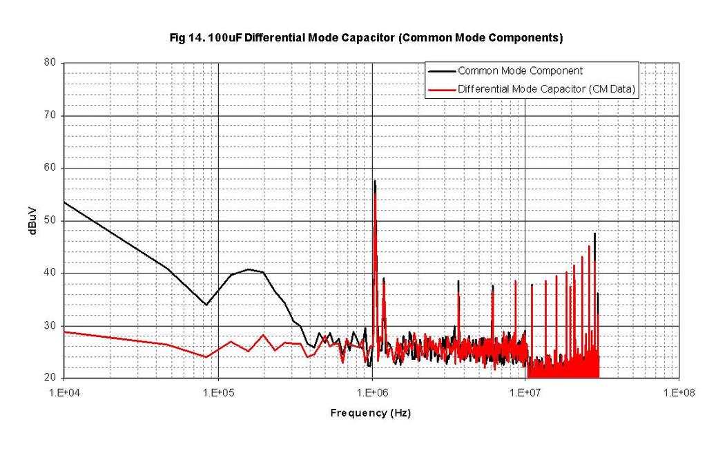
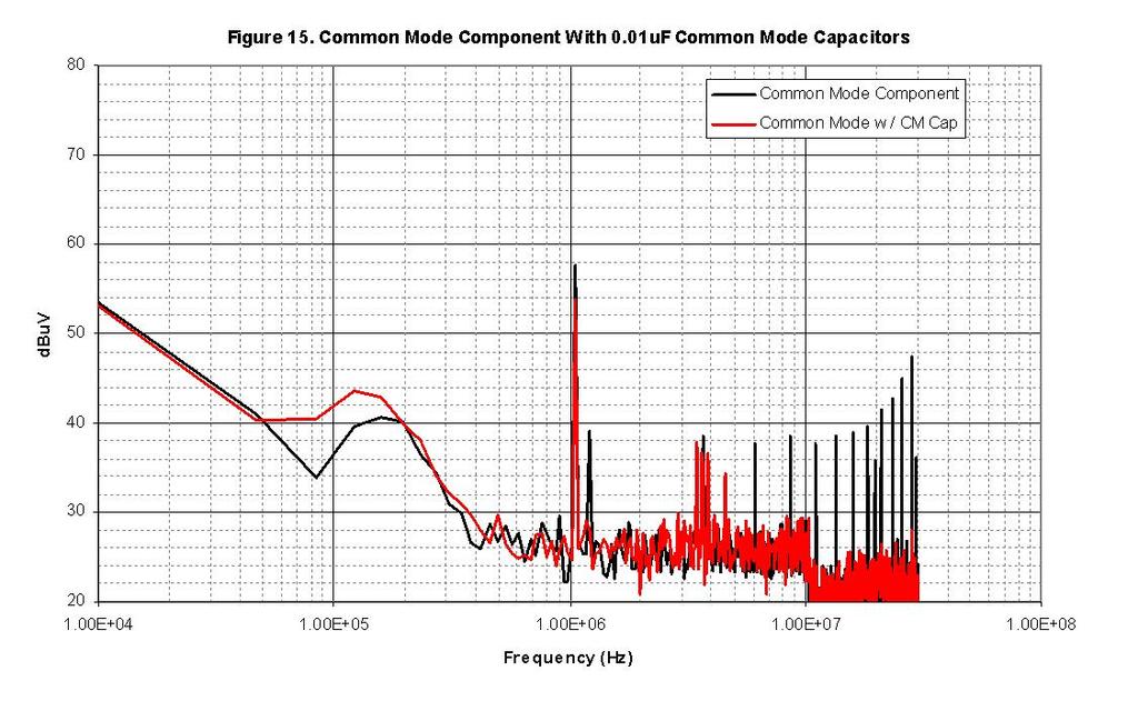
4 tial mode component dominates over the frequency range of 10 khz to 6 MHz. The common mode component dominates above 6 MHz. Step 9. Included above. Step 10. We first add a differential mode capacitor of 100uF and repeat the common mode and differential mode measurements. We find a significant decrease in the differential mode component and small change to the common mode component. See Figure 13 for the differential mode component and Figure 14 for the common mode component. Step 11. The 100uF differential mode capacitor is removed and replaced with a 0.01 uf common mode capacitor between each line and chassis. The common mode component is reduced for frequencies greater than 5 MHz. The differential mode component increases in the 2 MHz to 4 MHz range with a resonance at 3.2 MHz. The common mode component is shown in Figure 15 and the differential mode component is shown in Figure 16. The next configuration is the parallel series combination of the 100uF differential mode capacitor, 0.01uF common mode capacitors and differential mode inductors in each line. The differential mode component shows a resonance at 1.8 MHz and the common mode component is significantly reduced over the entire frequency range except for the local AM radio station at 1070 khz. The differential mode component is shown in Figure 17 and common mode component is in Figure 18. The final configuration to be tested is the same configuration as above with the addition of a 3.24 mh common mode choke. The resonance at 1.8 Mhz is reduced by 6 db for the differential mode component and the common mode component has little visible change. The differential mode component is shown in Figure 19 and the common mode component is shown in Figure 20. Step 12. The LISN-UP is removed from the test setup and the configuration shown in Figure 8 is used to measure the resultant conducted voltage emissions for both lines. The emissions are generally lower than 35dBuV except for the resonance at 1.8 MHz which is 47dBuV. 4
5 5
6 6
7 7
8 8
9 9
10 10

11 Summary and Conclusions The LISN UP is a valuable troubleshooting tool for the EMC Engineer that can help save time by enabling rapid diagnosis of the dominant noise mode. Diagnosing the dominant noise mode allows for efficient modification of the EMI filter. If the differential mode component is dominant over a specific frequency range the EMC Engineer can focus on the differential mode filter components rather than the common mode components. This also works for the common mode case. Background Information The LISN UP is based upon the device first proposed by Paul and Hardin in [ 1] The device is able to separate the differential mode and common mode components of the conducted voltage emissions. This is accomplished with RF transformers and impedance matching resistors to sum voltages using the pertinent phase information to discern the predominant noise modes. There has been other work done to separate the differential mode and common mode components of conducted noise emissions. The first documented work was from Toppeto in Naves work appeared in The method proposed by Toppeto involved a current transformer, barbell test fixture and a high pass filter.[ 3] This approach is more suited to conducted current measurements than voltage measurements. Nave proposed a Differential Mode Rejection Network (DMRN) that would sum the output voltages from the LISN RF Output port and only pass the common mode component since the differential mode voltages cancelled.[ 2] In practice, the DMRN depends on a highly balanced network for each leg and precision resistors. A slight imbalance or difference in resistance values could easily degrade the performance of the DMRN. Nave also spoke of a selectable mode rejection network. Phase and Amplitude Effects on LISN UP Accuracy The summation of two or more voltages depends on the relative amplitude and phase of each. Maximum addition of two signals occurs when they are the same amplitude and there is zero phase difference between the two voltages. Maximum cancellation occurs when the amplitudes are identical and the phase difference between the two voltages is 180 degrees. A slight amplitude or phase imbalance can adversely effect the measurement accuracy. A graph depicting the amplitude difference between two signals to be added is shown in Figure 22. It shows that for maximum addition the amplitude difference must be less than 0.5 db. A second graph depicting relative phase for cancellation is shown in Figure 23. It shows that the phase and amplitude imbalances must be small for maximum signal addition and cancellation. The rho term is the relative amplitude expressed as a linear ratio of the two voltages. References: 1. C.R. Paul and K.B. Hardin, Diagnosis and Reduction of Conducted Noise Emissions, IEEE Transactions on Electromagnetic Compatibility, November 1988, Vol. 30, No. 4, pp M.J. Nave, A Novel Differential Mode Rejection Net work for LISNs. IEEE EMCS Symposium Record, Denver, CO., 1989, pp A.A. Toppeto, Test Method to Differentiate Common Mode and Differential Mode Noise, Third Symposium and Technical Exhibition on EMC, Rotterdam, pp , May 1-3,

12 Fischer Custom Communications, Inc Earl Street Torrance, CA Phone: Fax:
Parallel Resonance Effect on Conducted Cm Current in Ac/Dc Power Supply
 International Journal of Engineering Science Invention ISSN (Online): 2319 6734, ISSN (Print): 2319 6726 Volume 2 Issue 6 ǁ June. 2013 ǁ PP.31-35 Parallel Resonance Effect on Conducted Cm Current in Ac/Dc
A Novel Measurement System for the Common-Mode- and Differential-Mode-Conducted Electromagnetic Interference
 Progress In Electromagnetics Research Letters, Vol. 48, 75 81, 014 A Novel Measurement System for the Common-Mode- and Differential-Mode-Conducted Electromagnetic Interference Qiang Feng *, Cheng Liao,
CS101. Conducted Susceptibility CS101. CS101 Maximum Current. CS101 Limits. Basis For CS101 Limits. Comparison To MIL-STD Vdc or Less
 Conducted Susceptibility CS1 Raymond K. Adams Fischer Custom Communications, Inc. 20603 Earl Street Torrance, CA 90503 (3)303-3300 radams@fischercc.com CS1 Applicability DC and AC Input Power Leads Does
DEPARTMENT FOR CONTINUING EDUCATION
 DEPARTMENT FOR CONTINUING EDUCATION Reduce EMI Emissions for FREE! by Bruce Archambeault, Ph.D. (reprinted with permission from Bruce Archambeault) Bruce Archambeault presents two courses during the University
ROD ANTENNA TESTING Complete article download from: EMI TESTING. Basic RE102 test (2-30 MHz)
") ROD ANTENNA TESTING Complete article download from: http://stevejensenconsultants.com/rod_ant.pdf EMI TESTING Steve Jensen Steve Jensen Consultants Inc. Sept. 26, 2005 Applicable for DO-160 sec. 21 and
ROD ANTENNA TESTING Complete article download from: http://stevejensenconsultants.com/rod_ant.pdf EMI TESTING Steve Jensen Steve Jensen Consultants Inc. Sept. 26, 2005 Applicable for DO-160 sec. 21 and
Suppression Techniques using X2Y as a Broadband EMI Filter IEEE International Symposium on EMC, Boston, MA
 Suppression Techniques using X2Y as a Broadband EMI Filter Jim Muccioli Tony Anthony Dave Anthony Dale Sanders X2Y Attenuators, LLC Erie, PA 16506-2972 www.x2y.com Email: x2y@x2y.com Bart Bouma Yageo/Phycomp
The Causes and Impact of EMI in Power Systems; Part 1. Chris Swartz
 The Causes and Impact of EMI in Power Systems; Part Chris Swartz Agenda Welcome and thank you for attending. Today I hope I can provide a overall better understanding of the origin of conducted EMI in
SIMULATION of EMC PERFORMANCE of GRID CONNECTED PV INVERTERS
 SIMULATION of EMC PERFORMANCE of GRID CONNECTED PV INVERTERS Qin Jiang School of Communications & Informatics Victoria University P.O. Box 14428, Melbourne City MC 8001 Australia Email: jq@sci.vu.edu.au
Testing for EMC Compliance: Approaches and Techniques October 12, 2006
 : Approaches and Techniques October 12, 2006 Ed Nakauchi EMI/EMC/ESD/EMP Consultant Emulex Corporation 1 Outline Discuss EMC Basics & Physics Fault Isolation Techniques Tools & Techniques Correlation Analyzer
Mitigation of Common mode Noise for PFC Boost Converter by Balancing Technique
 Mitigation of Common mode Noise for PFC Boost Converter by Balancing Technique Nasir *, Jon Cobb *Faculty of Science and Technology, Bournemouth University, Poole, UK, nasir@bournemouth.ac.uk, Faculty
Understanding and Optimizing Electromagnetic Compatibility in Switchmode Power Supplies
 Understanding and Optimizing Electromagnetic Compatibility in Switchmode Power Supplies 1 Definitions EMI = Electro Magnetic Interference EMC = Electro Magnetic Compatibility (No EMI) Three Components
Effectively Using the EM 6992 Near Field Probe Kit to Troubleshoot EMI Issues
 Effectively Using the EM 6992 Near Field Probe Kit to Troubleshoot EMI Issues Introduction The EM 6992 Probe Kit includes three magnetic (H) field and two electric (E) field passive, near field probes
Electromagnetic interference at the mains ports of an equipment
 Electromagnetic interference at the mains ports of an equipment Mircea Ion Buzdugan, Horia Bălan, Emil E. Simion, Tudor Ion Buzdugan Technical University from Cluj-Napoca, 15, Constantin Daicoviciu street,
Designing Your EMI Filter
 The Engineer s Guide to Designing Your EMI Filter TABLE OF CONTENTS Introduction Filter Classifications Why Do We Need EMI Filters Filter Configurations 2 2 3 3 How to Determine Which Configuration to
IC Decoupling and EMI Suppression using X2Y Technology
 IC Decoupling and EMI Suppression using X2Y Technology Summary Decoupling and EMI suppression of ICs is a complex system level engineering problem complicated by the desire for faster switching gates,
PERFORMANCE AND ANALYSIS OF DIFFERENTIAL MODE NOISE SEPERATION FOR POWER SUPPLIES
 PERFORMANCE AND ANALYSIS OF DIFFERENTIAL MODE NOISE SEPERATION FOR POWER SUPPLIES 1 G.THIAGU, 2 Dr.R.DHANASEKARAN 1 Research Scholar, Sathayabama University, Chennai 2 Professor & Director-Research, Syed
Common myths, fallacies and misconceptions in Electromagnetic Compatibility and their correction.
 Common myths, fallacies and misconceptions in Electromagnetic Compatibility and their correction. D. A. Weston EMC Consulting Inc 22-3-2010 These are some of the commonly held beliefs about EMC which are
Internal Model of X2Y Chip Technology
 Internal Model of X2Y Chip Technology Summary At high frequencies, traditional discrete components are significantly limited in performance by their parasitics, which are inherent in the design. For example,
Mixed Mode EMI Noise Level Measurement in SMPS
 American Journal of Applied Sciences 3 (5): 1824-1830, 2006 ISSN 1546-9239 2006 Science Publications Mixed Mode EMI Noise Level Measurement in SMPS 1 R.Dhanasekaran, 1 M.Rajaram and 2 S.N.Sivanandam 1
T + T /13/$ IEEE 236. the inverter s input impedances on the attenuation of a firstorder
 Emulation of Conducted Emissions of an Automotive Inverter for Filter Development in HV Networks M. Reuter *, T. Friedl, S. Tenbohlen, W. Köhler Institute of Power Transmission and High Voltage Technology
Differential-Mode Emissions
 Differential-Mode Emissions In Fig. 13-5, the primary purpose of the capacitor C F, however, is to filter the full-wave rectified ac line voltage. The filter capacitor is therefore a large-value, high-voltage
Chapter 12 Digital Circuit Radiation. Electromagnetic Compatibility Engineering. by Henry W. Ott
 Chapter 12 Digital Circuit Radiation Electromagnetic Compatibility Engineering by Henry W. Ott Forward Emission control should be treated as a design problem from the start, it should receive the necessary
Verifying Simulation Results with Measurements. Scott Piper General Motors
 Verifying Simulation Results with Measurements Scott Piper General Motors EM Simulation Software Can be easy to justify the purchase of software packages even costing tens of thousands of dollars Upper
Six-port scattering parameters of a three-phase mains choke for consistent modelling of common-mode and differential-mode response
 Six-port scattering parameters of a three-phase mains choke for consistent modelling of common-mode and differential-mode response S. Bönisch, A. Neumann, D. Bucke Hochschule Lausitz, Fakultät für Ingenieurwissenschaften
Output Filtering & Electromagnetic Noise Reduction
 Output Filtering & Electromagnetic Noise Reduction Application Note Assignment 14 November 2014 Stanley Karas Abstract The motivation of this application note is to both review what is meant by electromagnetic
Chapter 1 Introduction
 Chapter 1 Introduction 1.1 Background and Motivation In the field of power electronics, there is a trend for pushing up switching frequencies of switched-mode power supplies to reduce volume and weight.
Design of EMI Filters for DC-DC converter
 Design of EMI Filters for DC-DC converter J. L. Kotny*, T. Duquesne**, N. Idir** Univ. Lille Nord de France, F-59000 Lille, France * USTL, F-59650 Villeneuve d Ascq, France ** USTL, L2EP, F-59650 Villeneuve
EMC review for Belle II (Grounding & shielding plans) PXD DEPFET system
 PXD DEPFET system") EMC review for Belle II (Grounding & shielding plans) PXD DEPFET system Outline 1. Introduction 2. Grounding strategy Implementation aspects 3. Noise emission issues Test plans 4. Noise immunity issues
EMC review for Belle II (Grounding & shielding plans) PXD DEPFET system Outline 1. Introduction 2. Grounding strategy Implementation aspects 3. Noise emission issues Test plans 4. Noise immunity issues
Technology in Balance
 Technology in Balance A G1 G2 B Basic Structure Comparison Regular capacitors have two plates or electrodes surrounded by a dielectric material. There is capacitance between the two conductive plates within
Comparison of IC Conducted Emission Measurement Methods
 IEEE TRANSACTIONS ON INSTRUMENTATION AND MEASUREMENT, VOL. 52, NO. 3, JUNE 2003 839 Comparison of IC Conducted Emission Measurement Methods Franco Fiori, Member, IEEE, and Francesco Musolino, Member, IEEE
A NEW COMMON-MODE VOLTAGE PROBE FOR PREDICTING EMI FROM UNSHIELDED DIFFERENTIAL-PAIR CABLES
 A NEW COMMON-MODE VOLTAGE PROBE FOR PREDICTING EMI FROM UNSHIELDED DIFFERENTIAL-PAIR CABLES Neven Pischl Bay Networks Division of Nortel Networks Santa Clara, CA npischl@nortelnetworks.com (408) 495 3261
INSTRUCTION MANUAL For LINE IMPEDANCE STABILIZATION NETWORK. Model LI khz to 10 MHz
 Page 1 of 10 INSTRUCTION MANUAL For LINE IMPEDANCE STABILIZATION NETWORK Model LI-4100 10 khz to 10 MHz Page 2 of 10 Table of Contents 1.0 Introduction... 3 2.0 Product Description... 4 3.0 Product Specifications...
Technical Report Printed Circuit Board Decoupling Capacitor Performance For Optimum EMC Design
 Technical Report Printed Circuit Board Decoupling Capacitor Performance For Optimum EMC Design Bruce Archambeault, Ph.D. Doug White Personal Systems Group Electromagnetic Compatibility Center of Competency
Computerized Conducted EMI Filter Design System Using LabVIEW and Its Application
 Proc. Natl. Sci. Counc. ROC(A) Vol. 25, No. 3, 2001. pp. 185-194 Computerized Conducted EMI Filter Design System Using LabVIEW and Its Application CHIA-NAN CHANG, HUI-KANG TENG, JUN-YUAN CHEN, AND HUANG-JEN
Anthony A. Anthony X2Y Attenuators, LLC 2700 West 21 st. Street, Suite 11 Erie, PA , USA
 Published in ITEM TM 2 Issue Page 12 by Robar Industries April 17, 2 Dynamic Testing Of A Dual Line Filter For Common And Differential Mode Attenuation using a Spectrum Analyzer James P. Muccioli, IEEE-Fellow
Techniques to reduce electromagnetic noise produced by wired electronic devices
 Rok / Year: Svazek / Volume: Číslo / Number: Jazyk / Language 2016 18 5 EN Techniques to reduce electromagnetic noise produced by wired electronic devices - Tomáš Chvátal xchvat02@stud.feec.vutbr.cz Faculty
CHAPTER 2 EQUIVALENT CIRCUIT MODELING OF CONDUCTED EMI BASED ON NOISE SOURCES AND IMPEDANCES
 29 CHAPTER 2 EQUIVALENT CIRCUIT MODELING OF CONDUCTED EMI BASED ON NOISE SOURCES AND IMPEDANCES A simple equivalent circuit modeling approach to describe Conducted EMI coupling system for the SPC is described
Application Note AN- 1094
 Application Note AN- 194 High Frequency Common Mode Analysis of Drive Systems with IRAMS Power Modules Cesare Bocchiola Table of Contents Page Section 1 : Introduction...2 Section 2 : The Conducted EMI
Heat sink. Insulator. µp Package. Heatsink is shown with parasitic coupling.
 X2Y Heatsink EMI Reduction Solution Summary Many OEM s have EMI problems caused by fast switching gates of IC devices. For end products sold to consumers, products must meet FCC Class B regulations for
MVDC Grounding and Common Mode Current Control
 MVDC Grounding and Common Mode Current Control Dr. Norbert H. Doerry Dr. John V. Amy Jr. IEEE Electric Ship Technologies Symposium (ESTS 2017) Arlington, VA August 15-17, 2017 7/14/2017 1 MVDC Reference
Common myths, fallacies and misconceptions in Electromagnetic Compatibility and their correction.
 Common myths, fallacies and misconceptions in Electromagnetic Compatibility and their correction. D. A. Weston EMC Consulting Inc 15-3-2013 1) First topic an introduction These are some of the commonly
Separation of common and differential mode conducted emission: Power combiner/splitters
 Downloaded from orbit.dtu.dk on: Aug 18, 18 Separation of common and differential mode conducted emission: Power combiner/splitters Andersen, Michael A. E.; Nielsen, Dennis; Thomsen, Ole Cornelius; Andersen,
GTEM cell simplifies EMC test
 GTEM cell simplifies EMC test Check the EMC performance of your designs in the lab with a GTEM cell and a spectrum analyzer. James P. Muccioli, Jastech EMC Consulting, Farmington Hills, MI Anthony A. Anthony
Electromagnetic Compatibility ( EMC )
") Electromagnetic Compatibility ( EMC ) Introduction EMC Testing 1-2 -1 Agenda System Radiated Interference Test System Conducted Interference Test 1-2 -2 System Radiated Interference Test Open-Area Test
Electromagnetic Compatibility ( EMC ) Introduction EMC Testing 1-2 -1 Agenda System Radiated Interference Test System Conducted Interference Test 1-2 -2 System Radiated Interference Test Open-Area Test
ITG Electronics, Inc.
 Mitigating EMI Problems & Filter Selection By Rafik Stepanian EMI Noise Generators A change of state (On/Off ) in an Electronic component has the potential to generate EMI. Typical examples are Electronic
TECHNICAL REPORT: CVEL EMI Source Modeling of the John Deere CA6 Motor Driver. C. Zhu, A. McDowell and T. Hubing Clemson University
 TECHNICAL REPORT: CVEL-11-029 EMI Source Modeling of the John Deere CA6 Motor Driver C. Zhu, A. McDowell and T. Hubing Clemson University October 1, 2011 Table of Contents Executive Summary... 3 1. Introduction...
A NEW APPROACH TO ANALYSE AND REDUCTION OF RADIO FREQUENCY CONDUCTED EMISSION DUE TO P.W.M IN A BUCK CONVERTER
 A NEW APPROACH TO ANALYSE AND REDUCTION OF RADIO FREQUENCY CONDUCTED EMISSION DUE TO P.W.M IN A BUCK CONVERTER A. FARHADI IRAN Electromagnetic Interference (EMI) which is also called as Radio Frequency
X2Y Capacitors for Instrumentation Amplifier RFI Suppression
 XY Capacitors for Instrumentation mplifier Summary Instrumentation amplifiers are often employed in hostile environments. Long sensor lead cables may pick-up substantial RF radiation, particularly if they
IN-CIRCUIT RF IMPEDANCE MEASUREMENT FOR EMI FILTER DESIGN IN SWITCHED MODE POWER SUPPLIES
 IN-CIRCUIT RF IMPEDANCE MEASUREMENT FOR EMI FILTER DESIGN IN SWITCHED MODE POWER SUPPLIES IN-CIRCUIT RF IMPEDANCE MEASUREMENT FOR EMI FILTER DESIGN IN SWITCHED MODE POWER SUPPLIES DENG JUNHONG 2008 DENG
Chapter 16 PCB Layout and Stackup
 Chapter 16 PCB Layout and Stackup Electromagnetic Compatibility Engineering by Henry W. Ott Foreword The PCB represents the physical implementation of the schematic. The proper design and layout of a printed
EMC Immunity studies for front-end electronics in high-energy physics experiments
 EMC Immunity studies for front-end electronics in high-energy physics experiments F. Arteche*, C. Rivetta**, *CERN,1211 Geneve 23 Switzerland, **FERMILAB, P.O Box 0 MS341, Batavia IL 510 USA. e-mail: fernando.arteche@cern.ch,
ELECTROMAGNETIC COMPATIBILITY HANDBOOK 1. Chapter 8: Cable Modeling
 ELECTROMAGNETIC COMPATIBILITY HANDBOOK 1 Chapter 8: Cable Modeling Related to the topic in section 8.14, sometimes when an RF transmitter is connected to an unbalanced antenna fed against earth ground
Design and Verification of 400Hz Power Filter for Aircraft Switching Power Supply
 INTERNATIONAL JOURNAL OF CIRCUITS, SYSTEMS AND SIGNAL PROCESSING Volume 9, 25 Design and Verification of Hz Power Filter for Aircraft Switching Power Supply Ju-Min Lee, Heon-Wook Seo, Sung-Su Ahn, Jin-Dae
EMI Filters Demystified. By William R. Bill Limburg February 21, 2018 Phoenix Chapter, IEEE EMC Society
 EMI Filters Demystified By William R. Bill Limburg February 21, 2018 Phoenix Chapter, IEEE EMC Society An EMI Filter Defined An EMI filter is a network designed to prevent unwanted electrical conducted
Filter Considerations for the IBC
 APPLICATION NOTE AN:202 Filter Considerations for the IBC Mike DeGaetano Application Engineering Contents Page Introduction 1 IBC Attributes 1 Input Filtering Considerations 2 Damping and Converter Bandwidth
Design for Guaranteed EMC Compliance
 Clemson Vehicular Electronics Laboratory Reliable Automotive Electronics Automotive EMC Workshop April 29, 2013 Design for Guaranteed EMC Compliance Todd Hubing Clemson University EMC Requirements and
Description RF Explorer RFEAH-25 1 is a 25mm diameter, high performance near field H-Loop antenna.
 Description RF Explorer RFEAH-25 1 is a 25mm diameter, high performance near field H-Loop antenna. RFEAH-25 is a very sensitive, compact and easy to use H-loop near field antenna. The low-loss design exhibits
FLTR100V10 Filter Module 75 Vdc Input Maximum, 10 A Maximum
 GE Critical Power FLTR100V10 Filter Module 75 Vdc Input Maximum, 10 A Maximum RoHS Compliant The FLTR100V10 Filter Module is designed to reduce the conducted common-mode and differential-mode noise on
The Impact Of Signal Jumping Across Multiple Different Reference Planes On Electromagnetic Compatibility
 Copyright by Dr. Andrew David Norte, All Rights Reserved March 18 th, 2012 The Impact Of Signal Jumping Across Multiple Different Reference Planes On Electromagnetic Compatibility David Norte, PhD www.the-signal-and-power-integrity-institute.com
How EMxpert Diagnoses Board-Level EMC Design Issues
 Application Report EMxpert July 2011 - Cédric Caudron How EMxpert Diagnoses Board-Level EMC Design Issues ABSTRACT EMxpert provides board-level design teams with world-leading fast magnetic very-near-field
Conducted EMI Simulation of Switched Mode Power Supply
 Conducted EMI Simulation of Switched Mode Power Supply Hongyu Li #1, David Pommerenke #2, Weifeng Pan #3, Shuai Xu *4, Huasheng Ren *5, Fantao Meng *6, Xinghai Zhang *7 # EMC Laboratory, Missouri University
Model 3725/2M. Line Impedance Stabilization Network (LISN) User Manual
 User Manual") Model 3725/2M Line Impedance Stabilization Network (LISN) User Manual ETS-Lindgren L.P. reserves the right to make changes to any product described herein in order to improve function, design, or for any
Model 3725/2M Line Impedance Stabilization Network (LISN) User Manual ETS-Lindgren L.P. reserves the right to make changes to any product described herein in order to improve function, design, or for any
A New Method for the Calibration of the mv Ranges of an AC Measurement Standard
 A New Method for the Calibration of the mv Ranges of an AC Measurement Standard Speaker/Author Neil Faulkner Fluke Corporation PO Box 9090, Everett, WA 98206 Phone: (425) 446-5538 FAX: (425) 446-5649 E-mail:
QPI-AN1 GENERAL APPLICATION NOTE QPI FAMILY BUS SUPPLY QPI CONVERTER
 QPI-AN1 GENERAL APPLICATION NOTE QPI FAMILY EMI control is a complex design task that is highly dependent on many design elements. Like passive filters, active filters for conducted noise require careful
Methods for Reducing Emissions from Switching Power Circuits. A. McDowell, C. Zhu and T. Hubing
 Methods for Reducing Emissions from Switching Power Circuits A. McDowell, C. Zhu and T. Hubing 1 Objective To reduce radiated emissions and other forms of interference from power inverter circuits, by
1000BASE-T1 EMC Test Specification for Common Mode Chokes
 IEEE 1000BASE-T1 EMC Test Specification for Common Mode Chokes Version 1.0 Author & Company Dr. Bernd Körber, FTZ Zwickau Title 1000BASE-T1 EMC Test Specification for Common Mode Chokes Version 1.0 Date
Overview of the ATLAS Electromagnetic Compatibility Policy
 Overview of the ATLAS Electromagnetic Compatibility Policy G. Blanchot CERN, CH-1211 Geneva 23, Switzerland Georges.Blanchot@cern.ch Abstract The electromagnetic compatibility of ATLAS electronic equipments
EMI Filter Design Example. This is a very small 1 hour session based on our 2 Day EMI Filter Design Workshop
 Biricha Digital Power Ltd Parkway Dr Reading RG4 6XG UK April - 208 EMI Filter Design Example This is a very small hour session based on our 2 Day EMI Filter Design Workshop Dr Ali Shirsavar Biricha Digital
Electromagnetic Compliance: Pre-Compliance Conducted Emissions Testing October 19, 2017
 Electromagnetic Compliance: Pre-Compliance Conducted Emissions Testing October 19, 2017 Electromagnetic compliance (EMC) testing involves measuring the radio frequency (RF) output of a product and comparing
Common and Differential Mode EMI Filters for Power Electronics
 SPEEDAM 28 International Symposium on Power Electronics, Electrical Drives, Automation and Motion Common and Differential Mode EMI Filters for Power Electronics V. Serrao, A. Lidozzi, L. Solero and A.
Analogue circuit design for RF immunity
 Analogue circuit design for RF immunity By EurIng Keith Armstrong, C.Eng, FIET, SMIEEE, www.cherryclough.com First published in The EMC Journal, Issue 84, September 2009, pp 28-32, www.theemcjournal.com
Radiated EMI Recognition and Identification from PCB Configuration Using Neural Network
 PIERS ONLINE, VOL. 3, NO., 007 5 Radiated EMI Recognition and Identification from PCB Configuration Using Neural Network P. Sujintanarat, P. Dangkham, S. Chaichana, K. Aunchaleevarapan, and P. Teekaput
Chapter 5 Electromagnetic interference in flash lamp pumped laser systems
 Chapter 5 Electromagnetic interference in flash lamp pumped laser systems This chapter presents the analysis and measurements of radiated near and far fields, and conducted emissions due to interconnects
Ileana-Diana Nicolae ICMET CRAIOVA UNIVERSITY OF CRAIOVA MAIN BUILDING FACULTY OF ELECTROTECHNICS
 The Designing, Realization and Testing of a Network Filter used to Reduce Electromagnetic Disturbances and to Improve the EMI for Static Switching Equipment Petre-Marian Nicolae Ileana-Diana Nicolae George
Bulk Current Injection Probe Test Procedure
 Bulk Current Injection Probe Test Procedure 1 TABLE OF CONTENTS INTRODUCTION 3 GENERAL INFORMATION 4 TEST METHODS 6 SAFETY 8 FIGURES 9 FORMULAS 12 MAINTENANCE 13 WARRANTY 14 2 INTRODUCTION CURRENT PROBE
Signal and Noise Measurement Techniques Using Magnetic Field Probes
 Signal and Noise Measurement Techniques Using Magnetic Field Probes Abstract: Magnetic loops have long been used by EMC personnel to sniff out sources of emissions in circuits and equipment. Additional
Research Paper ELECTROMAGNETIC INTERFERENCE REDUCTION IN CUK CONVERTER USING MODIFIED PWM TECHNIQUES
 Research Paper ELECTROMAGNETIC INTERFERENCE REDUCTION IN CUK CONVERTER USING MODIFIED PWM TECHNIQUES *1 Dr. Sivaraman P and 2 Prem P Address for Correspondence Department of Electrical and Electronics
FISCHER CUSTOM COMMUNICATIONS, INC.
 FISCHER CUSTOM COMMUNICATIONS, INC. Current Probe Catalog FISCHER CUSTOM COMMUNICATIONS, INC. Fischer Custom Communications, Inc., is a manufacturer of custom electric and magnetic field sensors for military
7. EMV Fachtagung. EMV-gerechtes Filterdesign. 23. April 2009, TU-Graz. Dr. Gunter Winkler (TU Graz) Dr. Bernd Deutschmann (Infineon Technologies AG)
 Dr. Bernd Deutschmann (Infineon Technologies AG)") 7. EMV Fachtagung 23. April 2009, TU-Graz EMV-gerechtes Filterdesign Dr. Gunter Winkler (TU Graz) Dr. Bernd Deutschmann (Infineon Technologies AG) Page 1 Agenda Filter design basics Filter Attenuation
7. EMV Fachtagung 23. April 2009, TU-Graz EMV-gerechtes Filterdesign Dr. Gunter Winkler (TU Graz) Dr. Bernd Deutschmann (Infineon Technologies AG) Page 1 Agenda Filter design basics Filter Attenuation
Model Near-Field Probe Set. User Manual
 Model 7405 Near-Field Probe Set User Manual ETS-Lindgren L.P. reserves the right to make changes to any product described herein in order to improve function, design, or for any other reason. Nothing contained
CHAPTER 4 MEASUREMENT OF NOISE SOURCE IMPEDANCE
 69 CHAPTER 4 MEASUREMENT OF NOISE SOURCE IMPEDANCE 4.1 INTRODUCTION EMI filter performance depends on the noise source impedance of the circuit and the noise load impedance at the test site. The noise
Solution of EMI Problems from Operation of Variable-Frequency Drives
 Pacific Gas and Electric Company Solution of EMI Problems from Operation of Variable-Frequency Drives Background Abrupt voltage transitions on the output terminals of a variable-frequency drive (VFD) are
Oversimplification of EMC filter selection
 Shortcomings of Simple EMC Filters Antoni Jan Nalborczyk MPE Ltd. Liverpool, United Kingdom Oversimplification of EMC filter selection to reduce size and cost can often be a false economy as anticipated
V1.3. TBLC08 50mH AC-LISN TBLC08
 V1.3 TBLC08 The TBLC08 is a Line Impedance Stabilization Network for the measurement of line-conducted interference within the range of 9kHz to 30MHz, according to the CISPR16 standard. The device is designed
Frequently Asked EMC Questions (and Answers)
") Frequently Asked EMC Questions (and Answers) Elya B. Joffe President Elect IEEE EMC Society e-mail: eb.joffe@ieee.org December 2, 2006 1 I think I know what the problem is 2 Top 10 EMC Questions 10, 9
Frequently Asked EMC Questions (and Answers) Elya B. Joffe President Elect IEEE EMC Society e-mail: eb.joffe@ieee.org December 2, 2006 1 I think I know what the problem is 2 Top 10 EMC Questions 10, 9
Harmonic Filtering in Variable Speed Drives
 Harmonic Filtering in Variable Speed Drives Luca Dalessandro, Xiaoya Tan, Andrzej Pietkiewicz, Martin Wüthrich, Norbert Häberle Schaffner EMV AG, Nordstrasse 11, 4542 Luterbach, Switzerland luca.dalessandro@schaffner.com
EMI AND BEL MAGNETIC ICM
 EMI AND BEL MAGNETIC ICM ABSTRACT Electromagnetic interference (EMI) in a local area network (LAN) system is a common problem that every LAN system designer faces, and it is a growing problem because the
QPI-5L. 14 Amp Active EMI Filter for 24 V DC Bus. Features. Description. Applications 查询 QPI-5L 供应商. QuietPower
 查询 5L 供应商 5L QuietPower 14 Amp Active EMI Filter for 24 V DC Bus Description The 5 active EMI filter attenuates conducted common-mode (CM) and differential-mode (DM) noise over the CISPR22 frequency range
Exercise 1: Series RLC Circuits
 RLC Circuits AC 2 Fundamentals Exercise 1: Series RLC Circuits EXERCISE OBJECTIVE When you have completed this exercise, you will be able to analyze series RLC circuits by using calculations and measurements.
32 AMP Single Phase Power Filter
 32 AMP Single Phase Power Filter Mil Std 188-125 Part 1 is a military document titled HIGH ALTITUDE ELECTROMAGNETIC PULSE (HEMP) PROTECTION FOR GROUND-BASED C4I FACILITIES PERFORMING CRITICAL, TIME URGENT
Power Line Impedance Characterization of Automotive Loads at the Power Line Communication Frequency Range
 Power Line Impedance Characterization of Automotive Loads at the Power Line Communication Frequency Range Marc Aragón, Mauricio Salinas, Pere J. Riu and Ferran Silva Grup de Compatibilitat Electromagnètica
A Modified Single Phase Inverter Topology with Active Common Mode Voltage Cancellation
 A Modified Single Phase Inverter Topology with Active Common Mode Voltage Cancellation A. Rao *, T.A. Lipo University of Wisconsin Madison 1415, Engineering Drive Madison, WI 53706, USA * Email: arao@cae.wisc.edu
Cross Coupling Between Power and Signal Traces on Printed Circuit Boards
 Cross Coupling Between Power and Signal Traces on Printed Circuit Boards Dr. Zorica Pantic-Tanner Edwin Salgado Franz Gisin San Francisco State University Silicon Graphics Inc. Silicon Graphics Inc. 1600
Failing EMC testing? > 50% of products fail EMC testing first time around
 Failing EMC testing? > 50% of products fail EMC testing first time around Situation An engineer of a small or medium size enterprise usually has to rely on his experience and on best practice methods in
Introduction to Electromagnetic Compatibility
 Introduction to Electromagnetic Compatibility Second Edition CLAYTON R. PAUL Department of Electrical and Computer Engineering, School of Engineering, Mercer University, Macon, Georgia and Emeritus Professor
PLEASE NOTE! THIS IS PARALLEL PUBLISHED VERSION / SELF-ARCHIVED VERSION OF THE OF THE ORIGINAL ARTICLE
 PLEASE NOTE! THIS IS PARALLEL PUBLISHED VERSION / SELF-ARCHIVED VERSION OF THE OF THE ORIGINAL ARTICLE This is an electronic reprint of the original article. This version may differ from the original in
Analysis of a PCB-Chassis System Including Different Sizes of Multiple Planes Based on SPICE
 Analysis of a PCB-Chassis System Including Different Sizes of Multiple Planes Based on SPICE Naoki Kobayashi (1), Todd Hubing (2) and Takashi Harada (1) (1) NEC, System Jisso Research Laboratories, Kanagawa,
Crystal Radio Engineering Diode Detectors
 by Kenneth A. Kuhn Feb. 3, 2008, (draft more to come) A diode is a non-linear device that conducts electrical current significantly better in what is referred to as the forward direction than in the reverse
Physical Test Setup for Impulse Noise Testing
 Physical Test Setup for Impulse Noise Testing Larry Cohen Overview Purpose: Use measurement results for the EM coupling (Campbell) clamp to determine a stable physical test setup for impulse noise testing.
Hidden schematics of EMI filters
 International Conference on Renewable Energies and Power Quality (ICREPQ 6) Madrid (Spain), 4 th to 6 th May, 26 exçxãtuäx XÇxÜzç tçw céãxü dâtä àç ]ÉâÜÇtÄ(RE&PQJ) ISSN 272-38 X, No.4 May 26 Hidden schematics