EFFECT OF SHIELDING ON CABLE RF INGRESS MEASUREMENTS LARRY COHEN
|
|
|
- Augustus Moore
- 6 years ago
- Views:
Transcription
1 EFFECT OF SHIELDING ON CABLE RF INGRESS MEASUREMENTS LARRY COHEN
2 OVERVIEW Purpose: Examine the common-mode and differential RF ingress levels of 4-pair UTP, F/UTP, and F/FTP cables at an (RJ45) MDI port termination under identical test conditions (layout geometry) from a controlled external RF field in an anechoic chamber Test data gathered from an earlier RF immunity study for 10GBase-T PHY equipment Measurements are coupled signal levels into various cable types and independent of any PHY design Use comparison of data from UTP sample and shielded cable samples to quantify benefit of cable shielding on reducing RF ingress Background for performing test Description of measurement procedure and test cases Plots of measured RF ingress for various cable samples and comparison of RF ingress levels between UTP and best shielded cable (F/FTP) Main results: Good shielded twisted pair cabling (F/FTP) can reduce common-mode ingress levels by about 30 db and can reduce differential ingress from 15 to 30 db vs UTP cabling Use of shielded twisted pair cables can significantly improve RF immunity of data links allowing PHY implementations with lower transmit power and wider bandwidth than unshielded twisted pair (UTP) in the automotive environment
3 BACKGROUND FOR PERFORMING TEST Background issues We were using F/UTP and F/FTP shielded cable to prevent RF ingress from the attached test channel cabling while performing radiated immunity testing on 10GBase-T products Intent was to isolate the external field ingress effects solely to the PHY EUT (equipment under test) We observed some F/UTP patch cords allowed RF ingress levels comparable to UTP patch cords which created errors and reproducibility issues in our EUT test results Purpose of the original RF ingress measurement procedure Measure RF ingress level differences between UTP, F/UTP, and F/FTP from different vendor s cable samples under identical test conditions to determine relative shielding effectiveness Use a known calibrated external field strength (10 V/meter) near the MDI port interface to determine approximate ingress levels during an actual RF immunity test Measure RF ingress from 80 MHz to 1000 MHz For determining shield effectiveness, our main interest is the RF ingress level difference between the UTP cable and the best F/UTP or F/FTP cable


4 DESCRIPTION OF EVALUATED TWISTED PAIR CABLE TYPES UTP Unshielded twisted pair without any additional shielding F/UTP Single foil shield around all four pairs F/FTP Foil shield around each pair plus an additional single foil shield around all four pairs All cable types have four pairs with 100 Ω characteristic impedance for each pair
5 BASIC DESCRIPTION OF TEST SETUP TO MEASURE RF INGRESS Test was performed in a 3m anechoic chamber Very simple linear cable layout; did not use any complex layout geometry Total exposed cable length of 2 meters; 1.3 meters in fixed horizontal configuration E-field was locally monitored (and calibrated) near the MDI termination test fixture RJ45 port; calibration target was 10 V/meter Measured both common-mode and differential mode RF ingress levels for all cable samples Measured pair 1-2 on all cable samples to reduce impedance mismatch effect of RJ45 connector (did not use split pair 3-6) Simple shielded RJ45 termination fixture with no magnetic components, only an RJ45 connector with coaxial SMA connector breakouts Measured RF ingress from 100 MHz to 1000 MHz 100 MHz lower limit was due to limitations in the available test equipment Performed initial tests with no cable attached to the termination fixture to establish a measurement noise floor
6 CABLING RF INGRESS MEASUREMENT PROCEDURE Build test setup in chamber as shown in diagram; place 180-degree splitter on Pair 1-2 to initially measure differential-mode ingress Adjust output level of signal generator so that the measured E-field level is 10 V/meter; use an unmodulated carrier (CW) as the test signal No 80% AM carrier normally used in standard radiated immunity testing Measure and record ingress signal level with the spectrum analyzer at each frequency point Loss of coaxial cable between the splitter and spectrum analyzer subtracted from the raw measurement data, but not the insertion loss of the splitter (about 1 db) Using GPIB control, step signal generator at from 100 MHz to 1000 MHz at 10 MHz intervals; repeat previous three steps at each signal generator frequency Replace the 180-degree splitter with a 0-degree splitter to measure common-mode signal ingress Repeat above measurement sequence for common-mode ingress level on Pair 1-2 Repeat the entire above test sequence with different cable sample For final result differential-mode reference impedance is 100 W and common-mode reference impedance is 25 W (-50 dbm W, W)
7 SETUP TO MEASURE CABLE RF INGRESS FROM AN EXTERNAL RADIATED FIELD Shielded anechoic chamber Balun 3 meters Non-conductive cable support (80 cm height) 0-degree splitter for common-mode 180-degree splitter for differential-mode Power Splitter 50 RJ45 Termination Board inside shielded enclosure RJ45 All unused pairs terminated with 50 E-field sensor (for calibration) Antenna (1 meter height) 2 meters Test cable L 2 (1 to 10 meters) Ferrite clamp E-Field strength meter GPIB Ferrite clamp GPIB Control Host PC GPIB 50 RF Power Amplifier GPIB Signal Generator GPIB DM-CM Termination Block 100 Differential-mode and 75 Common-mode termination for all four pairs 50 Spectrum Analyzer GPIB
8 CABLING RF INGRESS MEASUREMENT TEST SETUP
9 Test cables MEASUREMENT TEST CASES No cable attached to termination box (determine measurement noise floor) Vendor A Cat 6A UTP (10 meters); unshielded twisted pair Vendor B Cat 6 F/UTP (50 feet); foil screen around all four pairs, no shield per pair Vendor C Cat 6 F/UTP (10 meters); foil screen around all four pairs, no shield per pair Vendor D Cat 6 F/FTP (10 meters); foil screen around all four pairs, foil shield per pair Plot only horizontal antenna polarization (dominant orientation) Total exposed cable length of 2 meters; 1.3 meters in fixed horizontal configuration Measured both differential-mode and common-mode ingress voltage Measured only Pair 1-2 for each cable sample; sufficient for performance comparison and minimal impedance distortion through RJ45 connector For final ingress level result is in dbm: Differential-mode reference impedance is 100 W and common-mode reference impedance is 25 W.
10
11
12
13
14
15
16 ESTIMATING DIFFERENTIAL-MODE RF INGRESS REDUCTION Chamber measurements indicate shielding reduced common-mode ingress by 30 db, but direct measurement of the differential ingress reduction was not possible Measured differential ingress levels for the F/FTP were at the measurement noise floor Differential-mode ingress caused by internal conversion of an externally induced common-mode signal into a differential signal within the cable (mode conversion) Conversion due to unbalanced impedance and/or external coupling between each conductor of the twisted pair Presence of an external shield may degrade the balance of a twisted pair due to the varying and non-uniform distance between each conductor and shield (conductor geometry crosssection); reduction may be less than for common-mode ingress Given the same cable balance as UTP, a differential mode ingress reduction of 30 db is achievable A coupling attenuation measurement from kish_3bp_01_0513 (slide #14) indicates 10 to 20 db reduction of differential ingress with Cat 6A F/UTP vs Cat 6A UTP Slides 11 and 12 of this presentation show about 5 db reduction in RF ingress for F/FTP vs. F/UTP potential lower bound of about 15 db improvement vs UTP F/FTP pair/shield cross-section geometry is similar to single pair STP
17 COUPLING ATTENUATION MEASUREMENT FROM KISH_3BP_01_0513 Cat 6A F/UTP Channel Cat 6A UTP Channel
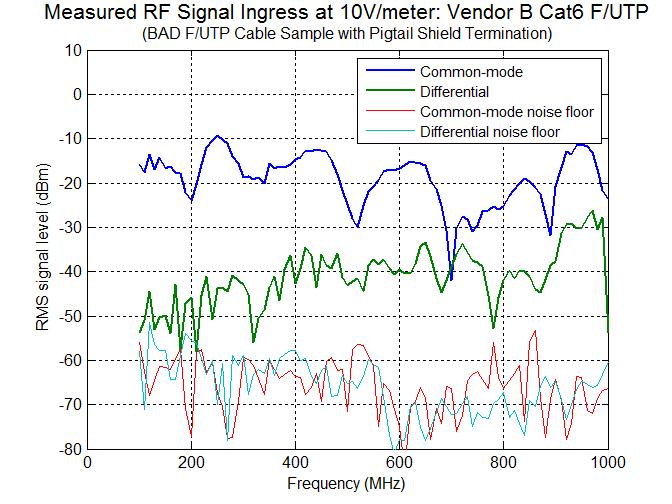
18 SUMMARY Measurements indicate good shielding (F/FTP) can reduce common-mode ingress levels by about 30 db vs unshielded cable (UTP) Measured differential ingress levels for the F/FTP were at the measurement noise floor, but estimates based on coupling attenuation measurements indicate differential ingress can be reduced from 15 to 30 db vs unshielded cable (UTP) Shielded cables are not alike in RF ingress performance and shielding effectiveness Significant performance differences from shield-to-connector termination (full 360-degree for good F/UTP and F/FTP cables, pigtail for bad F/UTP cable) Improper implementation can eliminate benefits Use of shielded twisted pair cables can significantly improve RF immunity of data links allowing PHY implementations with lower transmit power and wider bandwidth than unshielded twisted pair (UTP) in the automotive environment
19
Physical Test Setup for Impulse Noise Testing
 Physical Test Setup for Impulse Noise Testing Larry Cohen Overview Purpose: Use measurement results for the EM coupling (Campbell) clamp to determine a stable physical test setup for impulse noise testing.
Methods for Testing Impulse Noise Tolerance
 Methods for Testing Impulse Noise Tolerance May,6,2015 Larry Cohen Overview Purpose: Describe some potential test methods for impulse noise tolerance What we will cover in this presentation: Discuss need
A Proposed Specification for RFI Ingress Limit in 802.3ch Automotive Links. Ramin Farjadrad Larry Cohen Aquantia Corp.
 A Proposed Specification for RFI Ingress Limit in 802.3ch Automotive Links Ramin Farjadrad Larry Cohen Aquantia Corp. Narrowband RF Interference RF Interference Coupling to Differential Pairs ALSE 80MHz
Impulse Noise Measurement Test Setup
 Impulse Noise Measurement Test Setup 1/27/2015 Ramin Shirani Larry Cohen Impulse Noise Problem Overview Problem: Impulse noise events in the enterprise environment may degrade the operational BER of otherwise
10 Mb/s Single Twisted Pair Ethernet Conducted Immunity Steffen Graber Pepperl+Fuchs
 10 Mb/s Single Twisted Pair Ethernet Conducted Immunity Steffen Graber Pepperl+Fuchs IEEE P802.3cg 10 Mb/s Single Twisted Pair Ethernet Task Force 1/15/2019 1 Content EMC Generator Noise Amplitude Coupling-Decoupling-Network
Immunity Test System RIS 3000 / RIS 6000 acc. to IEC/EN
 Description The setup of a radiated immunity test system can be done in the conventional way with many separate instruments or in a more comfortable and less risky way with our new EMC control unit, type
4GHz / 6GHz Radiation Measurement System
 4GHz / 6GHz Radiation Measurement System The MegiQ Radiation Measurement System (RMS) is a compact test system that performs 3-axis radiation pattern measurement in non-anechoic spaces. With a frequency
Chapter 12: Transmission Lines. EET-223: RF Communication Circuits Walter Lara
 Chapter 12: Transmission Lines EET-223: RF Communication Circuits Walter Lara Introduction A transmission line can be defined as the conductive connections between system elements that carry signal power.
Common Impedance Shield Coupling
 Common Impedance Shield Coupling When a coaxial cable is used at low frequencies and the shield is grounded at both ends, V R I IN S S The shield serves two functions: 1. the return conductor for the signal;
Cabling Ad Hoc Cat 5e Measurements
 Cabling Ad Hoc Cat 5e Measurements Larry Cohen Solarflare Communications 1 Overview Cabling Ad Hoc Test Plan Measurement One Cat 5e horizontal cable sample, four test channel configurations characterized
Title: Test on 5.8 GHz Band Outdoor WiFi (802.11b/g) Wireless Base Station
 Wireless Base Station") Page 20 of 51 Pages 7.5. Conducted spurious emission 7.5.1. Requirements: Clause 15.247(d). In any 100 khz bandwidth outside the frequency band in which the spread spectrum or digitally modulated intentional
Page 20 of 51 Pages 7.5. Conducted spurious emission 7.5.1. Requirements: Clause 15.247(d). In any 100 khz bandwidth outside the frequency band in which the spread spectrum or digitally modulated intentional
Ave output power ANT 1(dBm) Ave output power ANT 2 (dbm)
 Ave output power ANT 2 (dbm)") Page 41 of 103 9.6. Test Result The test was performed with 802.11b Channel Frequency (MHz) power ANT 1(dBm) power ANT 2 (dbm) power ANT 1(mW) power ANT 2 (mw) Limits dbm / W Low 2412 7.20 7.37 5.248 5.458
Page 41 of 103 9.6. Test Result The test was performed with 802.11b Channel Frequency (MHz) power ANT 1(dBm) power ANT 2 (dbm) power ANT 1(mW) power ANT 2 (mw) Limits dbm / W Low 2412 7.20 7.37 5.248 5.458
Archived 3/18/10 USER MANUAL EMCO MODEL 3141 BICONILOG TM LOG-PERIODIC / T BOW-TIE ANTENNA Rev A 01/97
 USER MANUAL EMCO MODEL 3141 BICONILOG TM LOG-PERIODIC / T BOW-TIE ANTENNA 399236 Rev A 01/97 GENERAL DESCRIPTION The EMCO Model 3141 is the latest evolution in the popular bow-tie/log periodic combination
Influence of Aging Effects on Cables. Influence of Aging Effects on RF behavior Including Mode Conversion of STP and UTP Cables
 Influence of Aging Effects on RF behavior Including Mode Conversion of STP and UTP Cables Josef Ohni Research Engineer Philipp Numberger Development Engineer 2017 IEEE-SA Ethernet & IP @ Automotive Technology
10GBASE-T Transmitter Key Specifications
 10GBASE-T Transmitter Key Specifications Sandeep Gupta, Jose Tellado Teranetics, Santa Clara, CA sgupta@teranetics.com 5/19/2004 1 1000BASE-T Transmitter spec. overview Differential voltage at MDI output
Bill Ham Martin Ogbuokiri. This clause specifies the electrical performance requirements for shielded and unshielded cables.
 098-219r2 Prepared by: Ed Armstrong Zane Daggett Bill Ham Martin Ogbuokiri Date: 07-24-98 Revised: 09-29-98 Revised again: 10-14-98 Revised again: 12-2-98 Revised again: 01-18-99 1. REQUIREMENTS FOR SPI-3
Report Of. Shielding Effectiveness Test For. DefenderShield. Test Date(s): September 1 October 2, 2012
: September 1 October 2, 2012") Report Of Test For Test Date(s): September 1 October 2, 2012 UST Project No: Total Number of Pages Contained Within This Report: 15 3505 Francis Circle Alpharetta, GA 30004 PH: 770-740-0717 Fax: 770-740-1508
Report Of Test For Test Date(s): September 1 October 2, 2012 UST Project No: Total Number of Pages Contained Within This Report: 15 3505 Francis Circle Alpharetta, GA 30004 PH: 770-740-0717 Fax: 770-740-1508
Verifying Simulation Results with Measurements. Scott Piper General Motors
 Verifying Simulation Results with Measurements Scott Piper General Motors EM Simulation Software Can be easy to justify the purchase of software packages even costing tens of thousands of dollars Upper
MEASUREMENTS OF COUPLING THROUGH BRAIDED SHIELD VIA NEW CONDUCTED IMMUNITY TECH- NIQUE
 Progress In Electromagnetics Research C, Vol. 11, 61 68, 2009 MEASUREMENTS OF COUPLING THROUGH BRAIDED SHIELD VIA NEW CONDUCTED IMMUNITY TECH- NIQUE M. Ghassempouri College of Electrical Engineering Iran
TEST REPORT. Table of Contents
 Page:2 of 43 Table of Contents 1. DOCUMENT POLICY AND TEST STATEMENT... 4 1.1 DOCUMENT POLICY... 4 1.2 TEST STATEMENT... 4 2. DESCRIPTION OF EUT AND TEST MODE... 4 2.1 GENERAL DESCRIPTION OF EUT... 4 2.2
Valon Synthesizer RFI Test Report
 Page: Page 1 of 10 VEGAS-003-A-REP Version: A Prepared By: Name(s) and Signature(s) Organization Date C.Beaudet NRAO-GB 2011-11-29 J.Ray NRAO-GB 2013-03-18 Page: Page 2 of 10 Change Record Version Date
Understanding the Unintended Antenna Behavior of a Product
 Understanding the Unintended Antenna Behavior of a Product Colin E. Brench Southwest Research Institute Electromagnetic Compatibility Research and Testing colin.brench@swri.org Radiating System Source
Intelix DIGI-VGASD Installation Manual
 Intelix DIGI-VGASD Installation Manual Introduction The Intelix DIGI-VGASD active balun set transmits VGA video, stereo audio, and IR or RS232 up to 350 feet over a single twisted pair cable. The balun
CONDUCTED RF EQUIPMENT POWER AMPLIFIERS. Practical RF Immunity System Design Considerations
 CONDUCTED RF EQUIPMENT POWER AMPLIFIERS Practical RF Immunity System Design Considerations 1 Designing a System Key considerations are the amplifier and antenna combination Determining what Power Amplifier
Normalized Site Attenuation Test Report
 NVLAP LAB CODE 200974-0 Normalized Site Attenuation Test Report Test Specification NORMALIZED SITE ATTENUATION (NSA) Range 30 MHz 1GHz using the methods of ANSI C63.4-2009; EN 50147-2 (1997); CISPR 16-1-4
Intelix DIGI-V3SD-R Installation Manual
 Intelix DIGI-V3SD-R Installation Manual Introduction When used in conjunction with a compatible send balun, distribution amplifier, or matrix switcher, the Intelix DIGI-V3SD-R active balun transmits component
TEST REPORT. Table of Contents
 Page:2 of 24 Table of Contents 1. DOCUMENT POLICY AND TEST STATEMENT... 3 1.1 DOCUMENT POLICY...3 1.2 TEST STATEMENT...3 2. DESCRIPTION OF EUT AND TEST MODE... 4 2.1 GENERAL DESCRIPTION OF EUT...4 2.2
Shielding Effectiveness Report HQDP
 HQDP Mates with QSH-DP, QTH-DP Description: 0.50mm 100Ω Differential 30 AWG Twinax Cable Assembly Samtec, Inc. 2005 All Rights Reserved Table of Contents Product Overview... 1 Test Overview... 1 Shielded
COAXIAL TRANSMISSION LINE COMMON-MODE CURRENT
 COAXIAL TRANSMISSION LINE COMMON-MODE CURRENT Introduction Coaxial transmission lines are popular for their wide frequency bandwidth and high resistance to electromagnetic interference (EMI). Coax cables
Test specification: Section (e)(1), Radiated emissions below 40 GHz Test procedure: ANSI C63.4, Sections 8.3.2, 13.2, 13.4 Test mode: Compliance
(1), Radiated emissions below 40 GHz Test procedure: ANSI C63.4, Sections 8.3.2, 13.2, 13.4 Test mode: Compliance") Test specification: Section 15.253(e)(1), Radiated emissions below 40 GHz Test procedure: ANSI C63.4, Sections 8.3.2, 13.2, 13.4 Plot 7.2.7 Radiated emission measurements at frequency 7280 MHz Low channel
Test specification: Section 15.253(e)(1), Radiated emissions below 40 GHz Test procedure: ANSI C63.4, Sections 8.3.2, 13.2, 13.4 Plot 7.2.7 Radiated emission measurements at frequency 7280 MHz Low channel
EMC TEST REPORT. for. Coliy Technology Co.,Ltd. Fluxgate Gaussmeter
 Page 1 of 48 EMC TEST REPORT for Coliy Technology Co.,Ltd. Fluxgate Gaussmeter Prepared for : Coliy Technology Co.,Ltd. Address : Block B,9 th Floor,Xinzhongtai Business Building,Gushu 2nd Road,Xi Town,Bao
7. Transmitter Radiated Spurious Emissions and Conducted Spurious Emission
 7. Transmitter Radiated Spurious Emissions and Conducted Spurious Emission 7.1 Test Setup Refer to the APPENDIX I. 7.2 Limit According to 15.247(d), in any 100 khz bandwidth outside the frequency band
Spectrian Dual Mode Cellular Power Amplifier Model No.: SCLPA 800 CR FCC ID: I2ONTHX51AA
 A Class II Permissive Change - FCC Part 22 Type Acceptance Test Report for Spectrian Dual Mode Cellular Power Amplifier Model No.: SCLPA 800 CR FCC ID: I2ONTHX51AA Date of Report: May 26, 1999 Total No.
PARAMETER CONDITIONS TYPICAL PERFORMANCE Operating Supply Voltage 3.1V to 3.5V Supply Current V CC = 3.3V, LO applied 152mA
 DESCRIPTION LT5578 Demonstration circuit 1545A-x is a high linearity upconverting mixer featuring the LT5578. The LT 5578 is a high performance upconverting mixer IC optimized for output frequencies in
Shielding Effectiveness Summary Results for RadiaShield Technologies, Inc. RadiaShield Fabric
 Test Date(s): July 9 through July 19, 2010 UST Project Number: 10-0164 Summary Results for Product Description The Sample Under Test (SUT) is the. The SUT is a textile which is used as a protective shield
RF Emissions Test Report To Determine Compliance With: FCC, Part 15 Rules and Regulations
 RF Emissions Test Report To Determine Compliance With: FCC, Part 15 Rules and Regulations Model numbers: HT130022 Rev. B. December 17, 2002 Manufacturer: HQ, Inc. 210 9th Steet Drive Palmetto, FL 34221
Electromagnetic Compatibility ( EMC )
") Electromagnetic Compatibility ( EMC ) Introduction EMC Testing 1-2 -1 Agenda System Radiated Interference Test System Conducted Interference Test 1-2 -2 System Radiated Interference Test Open-Area Test
Electromagnetic Compatibility ( EMC ) Introduction EMC Testing 1-2 -1 Agenda System Radiated Interference Test System Conducted Interference Test 1-2 -2 System Radiated Interference Test Open-Area Test
TEST REPORT. Table of Contents
 Page:2 of 28 Table of Contents 1. DOCUMENT POLICY AND TEST STATEMENT... 3 1.1 DOCUMENT POLICY... 3 1.2 TEST STATEMENT... 3 2. DESCRIPTION OF EUT AND TEST MODE... 4 2.1 GENERAL DESCRIPTION OF EUT... 4 2.2
OPEN TEM CELLS FOR EMC PRE-COMPLIANCE TESTING
 1 Introduction Radiated emission tests are typically carried out in anechoic chambers, using antennas to pick up the radiated signals. Due to bandwidth limitations, several antennas are required to cover
Trees, vegetation, buildings etc.
 EMC Measurements Test Site Locations Open Area (Field) Test Site Obstruction Free Trees, vegetation, buildings etc. Chamber or Screened Room Smaller Equipments Attenuate external fields (about 100dB) External
FCC ID: A3LSLS-BD106Q. Report No.: HCT-RF-1801-FC003. Plot Data for Output Port 2_QPSK 9 khz ~ 150 khz Middle channel 150 khz ~ 30 MHz Low channel
 Plot Data for Output Port 2_QPSK 9 khz ~ 150 khz Middle channel 150 khz ~ 30 MHz Low channel 30 MHz ~ 1 GHz Middle channel 1 GHz ~ 2.491 GHz Low channel 2.695 GHz ~ 12.75 GHz High channel 12.75 GHz ~ 26.5
CATALOG. Network Access & Connectivity
 Baluns convert the G.703 interface from unbalanced 75-ohm to balanced -ohm terminations. Patton s baluns use dual BNC connectors (Models 460 and 464) or dual 1.6/5.6 coax connectors (Models 465 and 466)
CHAPTER 6 EMI EMC MEASUREMENTS AND STANDARDS FOR TRACKED VEHICLES (MIL APPLICATION)
") 147 CHAPTER 6 EMI EMC MEASUREMENTS AND STANDARDS FOR TRACKED VEHICLES (MIL APPLICATION) 6.1 INTRODUCTION The electrical and electronic devices, circuits and systems are capable of emitting the electromagnetic
147 CHAPTER 6 EMI EMC MEASUREMENTS AND STANDARDS FOR TRACKED VEHICLES (MIL APPLICATION) 6.1 INTRODUCTION The electrical and electronic devices, circuits and systems are capable of emitting the electromagnetic
A Test Lab Techno Corp. Report Number:1410FR27
 Mode 5: IEEE 802.11n 2.4GHz 40MHz Link Mode 2422 2437 2452 Page 41 of 85 9 Out of Band Conducted Emissions Measurement 9.1. Limit In any 100 khz bandwidth outside the frequency band in which the spread
AUTOMOTIVE ETHERNET CONSORTIUM
 AUTOMOTIVE ETHERNET CONSORTIUM Clause 96 100BASE-T1 Physical Medium Attachment Test Suite Version 1.0 Technical Document Last Updated: March 9, 2016 Automotive Ethernet Consortium 21 Madbury Rd, Suite
RF Characterization Report
 SMA-J-P-H-ST-MT1 Mated with: RF316-01SP1-01BJ1-0305 Description: 50-Ω SMA Board Mount Jack, Mixed Technology Samtec, Inc. 2005 All Rights Reserved Table of Contents Introduction...1 Product Description...1
Overview of EMC Regulations and Testing. Prof. Tzong-Lin Wu Department of Electrical Engineering National Taiwan University
 Overview of EMC Regulations and Testing Prof. Tzong-Lin Wu Department of Electrical Engineering National Taiwan University What is EMC Electro-Magnetic Compatibility ( 電磁相容 ) EMC EMI (Interference) Conducted
OPEN TEM CELLS FOR EMC PRE-COMPLIANCE TESTING
 1 Introduction Radiated emission tests are typically carried out in anechoic chambers, using antennas to pick up the radiated signals. Due to bandwidth limitations, several antennas are required to cover
EN 55015: 2013 Clause Pass. EN 55015: 2013 Clause Pass. EN 55015: 2013 Clause Pass
 Reference No.: WTD15S0730643E Page 2 of 42 1 Test Summary Test Item Conducted Disturbance at Mains Terminal, 9kHz to 30MHz Radiation electromagnetic disturbance, 9kHz to 30MHz Radiation Emission, 30MHz
FISCHER CUSTOM COMMUNICATIONS, INC.
 FISCHER CUSTOM COMMUNICATIONS, INC. Current Probe Catalog FISCHER CUSTOM COMMUNICATIONS, INC. Fischer Custom Communications, Inc., is a manufacturer of custom electric and magnetic field sensors for military
Application Note # 5438
 Application Note # 5438 Electrical Noise in Motion Control Circuits 1. Origins of Electrical Noise Electrical noise appears in an electrical circuit through one of four routes: a. Impedance (Ground Loop)
ST-CCTV-VBAC8 8-Channel Active UTP Video Receiver
 INSTALLATION MANUAL 8-Channel Active UTP Video Receiver Copyright North American Cable Equipment, Inc. 1 PACKAGE CONTENTS This package contains: One 8-channel active UTP video receiver One AC power cord
Matric Limited Hill City Road R.R. #1 Box 421A Seneca, PA 16346
 FCC CERTIFICATION TEST REPORT for Hill City Road R.R. #1 Box 421A Seneca, PA 16346 FCC ID: K5B-TP105 May 14, 2001 Revised: June 18, 2001 WLL PROJECT #: 6182X This report may not be reproduced, except in
Range Considerations for RF Networks
 TI Technology Days 2010 Range Considerations for RF Networks Richard Wallace Abstract The antenna can be one of the most daunting components of wireless designs. Most information available relates to large
MDS-21 Absorbing Clamp, EZ-24 Ferrite Clamp
 Version 06.00 MDS-21 Absorbing Clamp, EZ-24 Ferrite Clamp July 2007 Measurement of disturbance power and screening effectiveness on cables Reproducible measurements of disturbance field strength and disturbance
Intelix DIGI-VGASD-R Installation Manual
 Intelix DIGI-VGASD-R Installation Manual Introduction The Intelix DIGI-VGASD-R active receiver balun transmits VGA video, stereo audio, and IR or RS232 up to 350 feet over a single twisted pair cable.
4 Channel Security Hubs
 4 Channel Security Hubs Operating Instructions KD-4PUV Four Channel Passive Transceiver KD-4AUVRX Four Channel Active Receiver KD-4AUVRX & KD-4PUV are multi-channel video hubs that allow for the transmission
Qualification testing of 100 ohm shielded channel, Class EA. Performed for Tyco Electronics Raychem N.V.
 We help ideas meet the real world DELTA Test Report DANAK TEST Reg. no. 19 Qualification testing of 100 ohm shielded channel, Class EA Performed for Tyco Electronics Raychem N.V. DANAK-19J1636 Project
COUPLING DECOUPLING NETWORK MODEL CDN-AF4
 COUPLING DECOUPLING NETWORK MODEL CDN-AF4 II Warranty Com-Power warrants to its Customers that the products it manufactures will be free from defects in materials and workmanship for a period of 2 years.
GPS Active Antenna With GPRS Measurement Report
 GPS Active Antenna With GPRS Measurement Report Summary: This report is to account for the measurement setup and results of 4x23mm and mm height GPS active antenna combined with GPRS antenna measurement.
VCCI TEST REPORT. According to. Class B ITE. Equipment : USB video camera
 VCCI TEST REPORT According to Class B ITE Equipment : USB video camera Model No. : V-U0011 Applicant : Logitech Far East Ltd. 2 Creation Road IV, Science-Based Ind. Park, Hsinchu, Taiwan. The test result
Requirements for Industrial Cabling Supporting Gigabit Applications for Control, A study of Noise
 Requirements for Industrial Cabling Supporting Gigabit Applications for Control, A study of Noise Bob Lounsbury Principal Engineer, Rockwell Automation Rockwell Automation Presented at the ODVA 2015 Industry
Features and Technical Specifications
 Features and Technical Specifications PRODU C T SUM M AR Y The HL9402 is a signal splitter and combiner that offers industry-best amplitude and phase match over a bandwidth of 500 khz to 20 GHz (-3 db).
Regarding RF Isolation for small Enclosures
 Regarding RF Isolation for small Enclosures IEEE electromagnetic society and IEEE standard board has published standards for measuring the shielding effectiveness (SE) of chambers. The measurement methods
87415A microwave system amplifier A microwave. system amplifier A microwave system amplifier A microwave.
 20 Amplifiers 83020A microwave 875A microwave 8308A microwave 8307A microwave 83006A microwave 8705C preamplifier 8705B preamplifier 83050/5A microwave The Agilent 83006/07/08/020/050/05A test s offer
Intelix DIGI-VGASD-S Installation Manual
 Intelix DIGI-VGASD-S Installation Manual Introduction The Intelix DIGI-VGASD-S active send balun transmits VGA video, stereo audio, and IR or RS232 up to 350 feet over a single twisted pair cable. The
RF Test Accessories. Antenna Coupler. TC-93010C fitted with F930102A TC-93013A. Frequency Range : 820 ~ 960 MHz. Frequency Range : 0.
 RF Test Accessories Antenna Coupler TC-93010C Tubular Type Antenna Coupler Frequency Range : 0.8 ~ 2GHz RF Connector : SMA(f) Weight : 60g Patent Pending # 2001-24403 Hole Size : 11mm TC-93010C fitted
Electromagnetic Compatibility
 Electromagnetic Compatibility Introduction to EMC International Standards Measurement Setups Emissions Applications for Switch-Mode Power Supplies Filters 1 What is EMC? A system is electromagnetic compatible
Keysight Technologies 8 Hints for Making Better Measurements Using RF Signal Generators. Application Note
 Keysight Technologies 8 Hints for Making Better Measurements Using RF Signal Generators Application Note 02 Keysight 8 Hints for Making Better Measurements Using RF Signal Generators - Application Note
ST-CCTV-VBAC16 16-Channel Active UTP Video Receiver
 INSTALLATION MANUAL ST-CCTV-VBAC16 16-Channel Active UTP Video Receiver Copyright North American Cable Equipment, Inc. 1 PACKAGE CONTENTS This package contains: One ST-CCTV-VBAC16 16-channel active UTP
Objectives of transmission lines
 Introduction to Transmission Lines Applications Telephone Cable TV (CATV, or Community Antenna Television) Broadband network High frequency (RF) circuits, e.g., circuit board, RF circuits, etc. Microwave
LTE Band 7. Channel
 Bandwidth 5MHz Frequency (MHz) LTE Band 7 Bandwidth 10MHz Peak To Average Ratio (db) Frequency Peak To Average Ratio (db) QPSK 16QAM (MHz) QPSK 16QAM 20775 2502.5 3.57 4.34 20800 2505 3.51 4.28 21100 2535
Broadband Current Probe Series Operation Manual
 Broadband Current Probe Series Operation Manual 1 TABLE OF CONTENTS INTRODUCTION 3 GENERAL INFORMATION 4 OPERATING INSTRUCTIONS 5 FORMULAS 6 MAINTENANCE 7 WARRANTY 8 2 INTRODUCTION CURRENT PROBE SPECIFICATIONS
AMPLIFIER RESEARCH... APPLICATION NOTE: 23
 AMPLIFIER RESEARCH... APPLICATION NOTE: 23 PRODUCTS THAT PROVIDE 200 V/m CW OR PM AT A DISTANCE OF 1 METER 1 The Amplifier / Antenna / Cell combinations shown in Table 1 provide various means of generating
QUICK START GUIDE FOR DEMONSTRATION CIRCUIT 678A 40MHZ TO 900MHZ DIRECT CONVERSION QUADRATURE DEMODULATOR
 DESCRIPTION QUICK START GUIDE FOR DEMONSTRATION CIRCUIT 678A LT5517 Demonstration circuit 678A is a 40MHz to 900MHz Direct Conversion Quadrature Demodulator featuring the LT5517. The LT 5517 is a direct
Channel 01 (2422MHz)
") Product : PC to TV Transmitter [u17] Test Item : RF Antenna Conducted Spurious Test Site : No.3 OATS Test Mode : Mode 4: Transmit (802.11n MCS0 15Mbps 40M-BW) Channel 01 (2422MHz) Page: 57 of 109 Page:
Product : PC to TV Transmitter [u17] Test Item : RF Antenna Conducted Spurious Test Site : No.3 OATS Test Mode : Mode 4: Transmit (802.11n MCS0 15Mbps 40M-BW) Channel 01 (2422MHz) Page: 57 of 109 Page:
VCCI TEST REPORT. According to. V-3/ , TECHNICAL REQUIREMENTS, Class B ITE. Equipment : USB video camera. Model No. : V-U0017 / V-U0021
 VCCI TEST REPORT According to V-3/2009.04, TECHNICAL REQUIREMENTS, Class B ITE Equipment : USB video camera Model No. : V-U0017 / V-U0021 Applicant : Logitech Far East Ltd. 2 Creation Road IV, Science-Based
Future In Radiated Immunity Testing
 Future In Radiated Immunity Testing Flynn Lawrence Flynn Lawrence is an Applications Engineer for AR RF/Microwave Instrumentation. At AR, Flynn is actively engaged in new application and product development
Development of a noval Switched Beam Antenna for Communications
 Master Thesis Presentation Development of a noval Switched Beam Antenna for Communications By Ashraf Abuelhaija Supervised by Prof. Dr.-Ing. Klaus Solbach Institute of Microwave and RF Technology Department
Electrical FOR:
 839.01 Electrical Hermon Laboratories Ltd. Harakevet Industrial Zone, Binyamina 30500, Israel Tel. +972-4-6288001 Fax. +972-4-6288277 E-mail: mail@hermonlabs.com TEST REPORT ACCORDING TO: EN 300 113-2
Keysight Technologies Techniques for Precise Cable and Antenna Measurements in the Field
 Keysight Technologies Techniques for Precise Cable and Antenna Measurements in the Field Using FieldFox handheld analyzers Application Note This application note introduces the practical aspects of cable
Measurement of RF Emissions from a Caterpillar Inc. MSS3s RF ID Key Fob
 Measurement of RF Emissions from a Caterpillar Inc. MSS3s RF ID Key Fob For Caterpillar Inc. 330 S.W. Adams Street Peoria, IL 61630 P.O. Number JBL 11260 Date Tested May 11, 2016 Test Personnel Mark Longinotti
1) Transmission Line Transformer a. First appeared on the scene in 1944 in a paper by George Guanella as a transmission line transformer, the 1:1
 Transmission Line Transformer a. First appeared on the scene in 1944 in a paper by George Guanella as a transmission line transformer, the 1:1") 1) Transmission Line Transformer a. First appeared on the scene in 1944 in a paper by George Guanella as a transmission line transformer, the 1:1 Guanella Balun is the basic building Balun building block.
1) Transmission Line Transformer a. First appeared on the scene in 1944 in a paper by George Guanella as a transmission line transformer, the 1:1 Guanella Balun is the basic building Balun building block.
Test Report. Product Name : Access Point Model No.: MS-6809 FCC ID.: I4L-MS6809
 Test Report Product Name : Access Point Model No.: MS-6809 FCC ID.: I4L-MS6809 Applicant : MICRO-STAR INT L Co., LTD Address : No 69, Li-De st., Jung-He City, Taipei Hsien, Taiwan, R.O.C Date of Receipt
University of New Hampshire InterOperability Laboratory Gigabit Ethernet Consortium
 University of New Hampshire InterOperability Laboratory Gigabit Ethernet Consortium As of June 18 th, 2003 the Gigabit Ethernet Consortium Clause 40 Physical Medium Attachment Conformance Test Suite Version
Electrical Field Distribution*
 Features l 30 MHz to MHz frequency range l Wide beamwidth illuminates a large uniform area l High power balun handles up to 10 kw RF input power l Tilt-angle, height and polarization are easily adjustable
Pico 900MHz 1W FHSS Module Model: p900 FCC ID: NS913P900. Applicant:
 Pico 900MHz 1W FHSS Module Model: p900 Applicant: Microhard Systems Inc. 150 Country Hills Landing NW Calgary, Alberta Canada T3K 5P3 In Accordance With Federal Communications Commission (FCC) Part 15,
L.S. Compliance, Inc. W66 N220 Commerce Court Cedarburg, WI
 L.S. Compliance, Inc. W66 N220 Commerce Court Cedarburg, WI 53012 262-375-4400 COMPLIANCE TESTING OF: Quartex Synchronization Transmitter Model FM-72 PREPARED FOR: Quartex, Division of Primex, Inc. 965
Contents. 1 Introduction. 2 System-Level Electrostatic Discharge (ESD) and Electrical Fast Transient. 3 Electromagnetic Interference
 and Electrical Fast Transient. 3 Electromagnetic Interference") Issue 3, October 2002 Electromagnetic Compatibility and Electrical Safety Contents Telcordia GR-1089 - Documentation Information Generic Requirements Notice Of Disclaimer................. iii Contents.......................................
Issue 3, October 2002 Electromagnetic Compatibility and Electrical Safety Contents Telcordia GR-1089 - Documentation Information Generic Requirements Notice Of Disclaimer................. iii Contents.......................................
AMPLIFIER RESEARCH... APPLICATION NOTE: 20
 AMPLIFIER RESEARCH... APPLICATION NOTE: 20 AMPLIFIER RESEARCH PRODUCTS THAT PROVIDE 20 V/m CW OR PM AT A DISTANCE OF 1 METER 1 The Amplifier / Antenna / Cell combinations shown in Table 1 provide various
ELEC Course Objectives/Proficiencies
 Lecture 1 -- to identify (and list examples of) intentional and unintentional receivers -- to list three (broad) ways of reducing/eliminating interference -- to explain the differences between conducted/radiated
Electromagnetic Effects, original release, dated 31 October Contents: 17 page document plus 13 Figures. Enclosure (1)
") Electromagnetic Effects, original release, dated 31 October 2005 Contents: 17 page document plus 13 Figures Enclosure (1) Electromagnetic effects. 1. Purpose. To ensure that the addition of fiber optic
Electromagnetic Effects, original release, dated 31 October 2005 Contents: 17 page document plus 13 Figures Enclosure (1) Electromagnetic effects. 1. Purpose. To ensure that the addition of fiber optic
Broadband Current Probe Series Operation Manual
 Broadband Current Probe Series Operation Manual 1 TABLE OF CONTENTS WARRANTY 3 INTRODUCTION 4 GENERAL INFORMATION 5 OPERATING INSTRUCTIONS 6 FORMULAS 7 MAINTENANCE 8 2 WARRANTY INFORMATION A.H. Systems
Calibration and Validation for Automotive EMC
 Calibration and Validation for Automotive EMC Wolfgang Müllner Patrick Preiner Alexander Kriz Seibersdorf Labor GmbH 2444 Seibersdorf, Austria http://rf.seibersdorf-laboratories.at rf@seibersdorf-laboratories.at
Bulk Current Injection Probe Test Procedure
 Bulk Current Injection Probe Test Procedure 1 TABLE OF CONTENTS INTRODUCTION 3 GENERAL INFORMATION 4 TEST METHODS 6 SAFETY 8 FIGURES 9 FORMULAS 12 MAINTENANCE 13 WARRANTY 14 2 INTRODUCTION CURRENT PROBE
Model 3140B BiConiLog Antenna User Manual
 Model 3140B BiConiLog Antenna User Manual Model 3140B mounted onto a 7-TR tripod (not included) ETS-Lindgren L.P. reserves the right to make changes to any product described herein in order to improve
Course Introduction Purpose Objectives Content Learning Time
 Course Introduction Purpose This course discusses techniques for analyzing and eliminating noise in microcontroller (MCU) and microprocessor (MPU) based embedded systems. Objectives Learn about a method
Electromagnetic Compatibility Test Report FCC test results of an automatic dog brush, model EUT: Type 1 AC/DC adaptor: SYS W2E
 Electromagnetic Compatibility Test Report FCC test results of an automatic dog brush, model EUT: Type 1 AC/DC adaptor: SYS1308-1809-W2E Customer Customer's representative In the capacity of Reference number
EMC Amplifiers Going Beyond the Basics to Ensure Successful Immunity Tests
 EMC Amplifiers Going Beyond the Basics to Ensure Successful Immunity Tests Paul Denisowski, Application Engineer Broadband amplifiers are used to generate the high field strengths required by EMC radiated
ELEC 0017: ELECTROMAGNETIC COMPATIBILITY LABORATORY SESSIONS
 Academic Year 2015-2016 ELEC 0017: ELECTROMAGNETIC COMPATIBILITY LABORATORY SESSIONS V. BEAUVOIS P. BEERTEN C. GEUZAINE 1 CONTENTS: EMC laboratory session 1: EMC tests of a commercial Christmas LED light