Bias-T Design Considerations for the LWA Brian Hicks and Bill Erickson May 21, 2008
|
|
|
- Sara Henry
- 6 years ago
- Views:
Transcription
1 Bias-T Design Considerations for the LWA Brian Hicks and Bill Erickson May 21, 2008 The strawman design document [1] for the LWA suggests that the Front End Electronics (FEE) could be powered through the use of a circuit known as a bias-t. We will discuss how a bias-t operates and present a low cost design optimized for performance within the LWA frequency range of 20 to 80 MHz. We highly recommend the use of bias-t based on discrete components incorporated directly into the LWA FEE and ARX subsystems. I. Introduction A bias-t is a three port network designed to provide power to remote devices, such as amplifiers, over the same coaxial cable that RF signals are conveyed. The basic topology, and means of operation, of a bias-t network suitable for LWA applications is given in Figure 1. Capacitor Passes RF and Blocks DC and Low Frequency (60 Hz) AC RF ONLY C1 L1 Shunt Capacitor Routes any remaining RF leakage to Ground, Increasing Isolation between RF Ports and DC Supply Port. RF + Power Inductor Blocks RF and Passes DC and Low Frequency (60 Hz) AC C2 DC Power Supply Figure 1 Basic Inductive Bias-T Commercially available bias-ts are available in both connectorized and surface mount versions. These units are typically expensive ($40 to $100) and, although designed to be wideband, often suffer in performance at frequencies below 50 MHz. By concentrating on an LWA specific bias-t we can achieve a significant cost savings. We will focus on presenting a bias-t circuit that is optimized for operation below 100 MHz and has the ability to supply a single polarization of an LWA FEE (230 ma). We will also deliver a circuit with a compact printed circuit board (PCB) footprint. 1
 on the DC port should not be considered optional (Figure 1).")
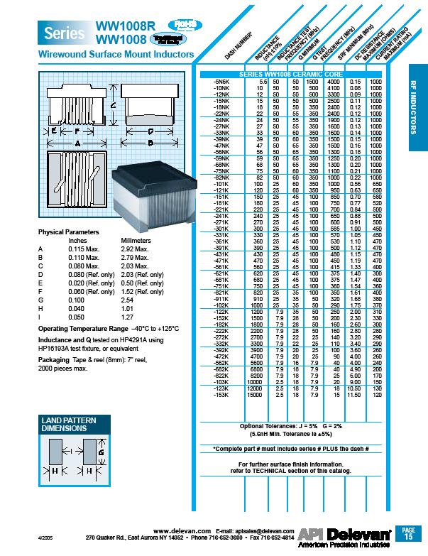
2 II. LWA Bias-T Design Considerations Consisting of one inductor and one capacitor the bias-t circuit is simple, but particular consideration must be given to component selection. Although not a part of the generic bias-t circuit, the shunt capacitor (C2) on the DC port should not be considered optional (Figure 1). Addition of this capacitance substantially increases isolation between the RF ports and the DC supply connection by routing any remaining RF leakage on the supply side of the inductor to ground (Figures 11, 12, and 13). It is especially important that the inductor be rated for the necessary current and should optimally have a minimum self resonant frequency (SRF) that is above the highest LWA frequencies. Throughout the entire LWA band, the inductor must present high impedance, and both capacitors must present low impedance; resonances must be avoided. Based on research and experience, we have selected the following components for consideration and testing: Capacitors (C1, C2): 0.1 μf Ceramic Capacitor (SMT 1208), Panasonic, ECJ-3VB1E104K Inductor (L1): 4.7 μh Wirewound Inductor (SMT 1008), Delevan, J III. LWA Bias-T Prototyping We have produced a PCB layout to enable us to reliably evaluate the performance of our bias-t with a variety of components (Figure 2). The SMA connectors featured here are only included as a convenience for testing. The basic orthogonal arrangement of L1 and C1 can be readily incorporated into the FEE and ARX regardless of the connectors these subsystems utilize. Figure 2 Bias-T Evaluation Board The circuit was evaluated both as a single unit and in the intended configuration with two bias-ts connected together and transferring power. In the configurations with two bias- Ts, we supplied 15 VDC at ~240 ma to a power-resistor load (~3.6 Watts dissipated) throughout the test (Figure 3). It was our intention to evaluate the performance of the inductors in the circuit while operating under load conditions representative of a G250R balun (FEE). 2


3 Figure 3 Characterization of the Bias-T Operating under Load In the single unit configurations we placed an SMA short on the DC port of the bias-t. It was our intention here to capture the performance of the single bias-t when connected to a DC power supply with very low output impedance. An Agilent N3383A vector network analyzer was used to characterize insertion loss (S21), return loss (S11 and S22), and isolation (S21 between RF and DC ports). A complete set of data is included in the measurements section of this report. IV. Observations and Recommendations The performance of the bias-t presented here is comparable to designs that we have already fielded and found to be entirely successful in operation. Within the LWA band, the performance of this circuit compares favorably to costly commercial units. The insertion loss of two of these cascaded bias-ts was found to be less than 0.2 db, and the aggregate return loss was found to be least -20 db. RF coupling from one dipole to another through the DC power network is a serious concern and potential source of indirect mutual coupling. It is important that significant attenuation be presented between the RF ports and the DC supply node of the bias-t. Direct mutual coupling between elements at a spacing of 4m has been demonstrated to be approximately -20 db, declining ~5 db for each 2m increase in spacing [2]. After 20 meters the mutual coupling between elements is approximately -60 db and only gradually diminishes with additional spacing [2]. Consequently, we recommend that feed system coupling be kept well below -80 db. The most expedient means of accomplishing this goal is the introduction of a capacitive shunt on the DC side of the bias-t. This can be seen on the schematic (Figure 14) as capacitor C2. It is typically a part of good engineering practice to incorporate bypass capacitors (such as C2) at DC supply nodes; we provide measurements here to emphasize the consequences of omitting this component. The isolation between the RF port and DC port of the bias-t without the capacitive shunt is seen to be inadequate in Figure 11. A definite improvement in isolation is seen when a 0.1 µf shunt is added at 3
4 the DC supply node (Figure 12). With the shunt, at least 60 db of attenuation between the RF ports and the DC supply port is achieved. An RF signal must run the gauntlet of two of networks consisting of L1 and C2 to traverse the DC feed ports of two bias-ts and get from one dipole signal chain to another. Greater than 100 db of attenuation is observed in this configuration (Figure 13). The prototype circuit fits within an 8.3 x 10 mm square on the circuit board; PCB space constraints should not be problematic. We recommend the use of a high-capacity DC power supply to supply power to the FEEs via a bias-t arrangement such as discussed here. This method of power distribution will spare the cost of installing and maintaining a separate power distribution network and eliminate unnecessary complexity in station installations. Because DC power is sourced via the center conductor of shielded coaxial cable, the resulting power network is effectively shielded at no additional cost. Candidate connectors for LWA RF cabling will likely incorporate conductive backshells which will act to further inhibit the introduction of RFI via the power distribution network. By incorporating a bias-t into the ARX, the option of allowing power to the antenna stands to be under control of the LWA Monitor and Control System (MCS) becomes inexpensive and straightforward to implement. This feature could prove valuable for diagnostics, maintenance, and station commissioning. V. Summary Table Operating Frequency 15 to 115 MHz Isolation 60 db Minimum Insertion Loss 0.2 db Maximum VSWR 1.2:1 Maximum Maximum DC Voltage 25 VDC Maximum DC Current 334 ma Size PCB Footprint Approximately 8.3 x 10 mm Parts Cost $0.92 4
5 VI. Measurements: -30 dbm Power Level for RF Stimulus 1. Measurements of a Single Bias-T Figure 4 Insertion Loss (S21) through a Single Bias-T with DC Port Shorted Figure 5 Return Loss (S11 and S22) into a Single Bias-T with DC Port Shorted 5

6 Figure 6 Return Loss (S11 and S22) into a Single Bias-T with DC Port Shorted (Smith) 2. Measurements of a Two Bias-Ts in Cascade Delivering 240 ma to a Load Figure 7 Insertion Loss through Two Bias-T Supplying 240 ma to a Resistive Load 6
7 Figure 8 Return Loss (S11 and S22) into Two Cascaded Bias-Ts Delivering 240 ma Figure 9 Return Loss (S11 and S22) into Two Cascaded Bias-Ts Delivering 240 ma (Smith) 7

8 Figure 10 SWR (S11 and S22) into Two Cascaded Bias-Ts Delivering 240 ma Figure 11 Single Bias-T Isolation between RF and DC Port without Capacitive Shunt. RF+DC Port 50Ω Terminated 8
.")
. RF ports 50Ω Terminated.")
9 Figure 12 Single Bias-T - Isolation between RF and DC Port with Capacitive Shunt (0.1 µf). RF+DC Port 50Ω Terminated Figure 13 Two Bias-Ts - Isolation between RF and RF Port with Capacitive Shunts (0.1 µf). RF ports 50Ω Terminated. Note: A power level of 0 dbm was used for this measurement. 9
10 VII. Bill of Materials Designation Value Tolerance Type Manufacturer Part No. C1, C2 0.1 μf 10% Capacitor, Ceramic Panasonic ECJ-3VB1E104K L1 4.7 μh +/- 5% Inductor, Unshielded (1206), X7R Delevan J Cost $0.056 (Quantities > 4000) $0.81 (Quantities > 2000) Total cost for each bias-t: $0.92 Total cost each antenna stand (4 bias-ts, two per polarization): $3.69 The results presented here are based on the use of Delevan part J for L1. Alternatively, part WW R could also be used. The former part is less expensive, and more readily available. Specifications for both parts are provided in the datasheet section at the end of this report. VIII. References [1] A Strawman Design for the Long Wavelength Array Stations, P.S. Ray (et. Al), April 11, 2006, LWA Memo #35. [2] Report on Mutual Coupling and Impedance Measurements on Large Blade Dipoles, B. Erickson, H. Schmitt, E. Polisensky, August 28, 2006, LWA Memo #53. 10
11 IX. Schematics and Layouts Figure 14 Bias-T Schematic 11

12 IX. Schematics and Layouts (Continued) Figure 15 Bias-T Evaluation PCB Note: Active portion of circuit fits within an 8 x 10 mm rectangle. 12
")
13 X. Datasheets (L1 and C1) 13
14 14
15 15
16 16
A Comparison of Two Power Combining Elements for LWA Active-Baluns Hybrid versus Wideband Transformer
 A Comparison of Two Power Combining Elements for LWA Active-Baluns - 180 Hybrid versus Wideband Transformer Brian Hicks, Nagini Paravastu, Paul Ray, and Bill Erickson May 9, 2007 We present a detailed
1 Mutual Coupling Measurements
 Report on Mutual Coupling and Impedance Measurements on Large Blade Dipoles Bill Erickson, Henrique Schmitt, Emil Polisensky Version 2.0-28 August 2006 In the following we describe the mutual coupling
Application Note 5038
 MGA-6P8 Buffer Amplifier for 10 MHz Application Application Note 038 Introduction The MGA-6P8 is a high isolation buffer amplifier based on Avago Technologies EPHEMT process. This application note discusses
California Eastern Laboratories
 California Eastern Laboratories AN143 Design of Power Amplifier Using the UPG2118K APPLICATION NOTE I. Introduction Renesas' UPG2118K is a 3-stage 1.5W GaAs MMIC power amplifier that is usable from approximately
Transmission Line Signal Sampling By Don Steinbach, AE6PM
 Transmission Line Signal Sampling By Don Steinbach, AE6PM When I was finalizing the mechanical layout of my remotely-operated 3-position coaxial antenna switch (Fig. 1), I wanted to include a way to bring
Application Note 5525
 Using the Wafer Scale Packaged Detector in 2 to 6 GHz Applications Application Note 5525 Introduction The is a broadband directional coupler with integrated temperature compensated detector designed for
A Low-Loss VHF/UHF Diplexer
 A Low-Loss / Diplexer Why use two lengths of expensive feed line when one will do? This hy box lets you use one feed line for both energy, simultaneously! By Pavel Zanek, OK1DNZ Do you need to operate
2. Design Recommendations when Using EZRadioPRO RF ICs
 EZRADIOPRO LAYOUT DESIGN GUIDE 1. Introduction The purpose of this application note is to help users design EZRadioPRO PCBs using design practices that allow for good RF performance. This application note
MWA REVB LNA Measurements
 1 MWA REVB LNA Measurements Hamdi Mani, Judd Bowman Abstract The MWA LNA (REVB) was measured on the Low Frequency Radio astronomy Lab using state of the art test equipment. S-parameters of the amplifier
Maxim Integrated Products 1
 19-3533; Rev 0; 1/05 MAX9996 Evaluation Kit General Description The MAX9996 evaluation kit (EV kit) simplifies the evaluation of the MAX9996 UMTS, DCS, and PCS base-station downconversion mixer. It is
Development of a noval Switched Beam Antenna for Communications
 Master Thesis Presentation Development of a noval Switched Beam Antenna for Communications By Ashraf Abuelhaija Supervised by Prof. Dr.-Ing. Klaus Solbach Institute of Microwave and RF Technology Department
Range Considerations for RF Networks
 TI Technology Days 2010 Range Considerations for RF Networks Richard Wallace Abstract The antenna can be one of the most daunting components of wireless designs. Most information available relates to large
ABA GHz Broadband Silicon RFIC Amplifier. Application Note 1349
 ABA-52563 3.5 GHz Broadband Silicon RFIC Amplifier Application Note 1349 Introduction Avago Technologies ABA-52563 is a low current silicon gain block RFIC amplifier housed in a 6-lead SC 70 (SOT- 363)
Amateur Extra Manual Chapter 9.4 Transmission Lines
 9.4 TRANSMISSION LINES (page 9-31) WAVELENGTH IN A FEED LINE (page 9-31) VELOCITY OF PROPAGATION (page 9-32) Speed of Wave in a Transmission Line VF = Velocity Factor = Speed of Light in a Vacuum Question
Network Evaluation for the PW A10 Schematic Review Prepared by David Green; W7NE Revision: 1.0 Complete Friday, October 20, 2006
 Network Evaluation for the PW A Schematic Review Prepared by David Green; W7NE Revision:. Complete Friday, October 2, 26 Parametric analysis of the L network was conducted in an effort to understand the
Testing a Prototype Blade Antenna at the LWDA Site
 1 Testing a Prototype Blade Antenna at the LWDA Site Nagini Paravastu, William Erickson, Ylva Pihlstrom, Namir Kassim, Brian Hicks August 30, 2005 September 1, 2005 I. INTRODUCTION This report summarizes
Review: The MFJ-223 Vector Impedance Antenna Analyzer Phil Salas AD5X
 Review: The Vector Impedance Antenna Analyzer Phil Salas AD5X The is MFJ s latest entry in the antenna analyzer market. Its TFT multi-color display provides a large amount of information on a very compact
A Transmatch for Balanced or Unbalanced Lines
 A Transmatch for Balanced or Unbalanced Lines Most modern transmitters are designed to operate into loads of approximately 50 Ω. Solid-state transmitters produce progressively lower output power as the
87415A microwave system amplifier A microwave. system amplifier A microwave system amplifier A microwave.
 20 Amplifiers 83020A microwave 875A microwave 8308A microwave 8307A microwave 83006A microwave 8705C preamplifier 8705B preamplifier 83050/5A microwave The Agilent 83006/07/08/020/050/05A test s offer
PART MAX2605EUT-T MAX2606EUT-T MAX2607EUT-T MAX2608EUT-T MAX2609EUT-T TOP VIEW IND GND. Maxim Integrated Products 1
 19-1673; Rev 0a; 4/02 EVALUATION KIT MANUAL AVAILABLE 45MHz to 650MHz, Integrated IF General Description The are compact, high-performance intermediate-frequency (IF) voltage-controlled oscillators (VCOs)
LM2462 Monolithic Triple 3 ns CRT Driver
 LM2462 Monolithic Triple 3 ns CRT Driver General Description The LM2462 is an integrated high voltage CRT driver circuit designed for use in color monitor applications. The IC contains three high input
The Design of A 125W L-Band GaN Power Amplifier
 Sheet Code RFi0613 White Paper The Design of A 125W L-Band GaN Power Amplifier This paper describes the design and evaluation of a single stage 125W L-Band GaN Power Amplifier using a low-cost packaged
The Amazing MFJ 269 Author Jack Tiley AD7FO
 The Amazing MFJ 269 Author Jack Tiley AD7FO ARRL Certified Emcomm and license class Instructor, Volunteer Examiner, EWA Technical Coordinator and President of the Inland Empire VHF Club What Can be Measured?
LoopBack Relay. GLB363 Series. With Built-in AC Bypass Capacitors / DC LoopBack Relay
 GLB363 Series With Built-in AC Bypass Capacitors / DC SERIES DESIGNATION GLB363 RELAY TYPE, Sensitive Coil, Surface Mount Ground Shield and Stub pins with AC Bypass Capacitors or No capacitor DESCRIPTION
Bill Ham Martin Ogbuokiri. This clause specifies the electrical performance requirements for shielded and unshielded cables.
 098-219r2 Prepared by: Ed Armstrong Zane Daggett Bill Ham Martin Ogbuokiri Date: 07-24-98 Revised: 09-29-98 Revised again: 10-14-98 Revised again: 12-2-98 Revised again: 01-18-99 1. REQUIREMENTS FOR SPI-3
EC6503 Transmission Lines and WaveguidesV Semester Question Bank
 UNIT I TRANSMISSION LINE THEORY A line of cascaded T sections & Transmission lines General Solution, Physicasignificance of the equations 1. Derive the two useful forms of equations for voltage and current
MAX2045/MAX2046/MAX2047 Evaluation Kits
 19-2793; Rev 0a; 4/03 MAX2045/MAX2046/MAX2047 Evaluation Kits General Description The MAX2045/MAX2046/MAX2047 evaluation kits (EV kits) simplify evaluation of the MAX2045/MAX2046/ MAX2047 vector multipliers.
JEREMY HALEY, WG9T LONGMONT AMATEUR RADIO CLUB. Longmont Amateur Radio Club
 RF IMPEDANCE AND THE SMITH CHART JEREMY HALEY, WG9T LONGMONT AMATEUR RADIO CLUB 1 RESISTANCE, REACTANCE, AND IMPEDANCE RESISTANCE Energy conversion to heat. REACTANCE Capacitance: Energy storage in electric
Chapter 12: Transmission Lines. EET-223: RF Communication Circuits Walter Lara
 Chapter 12: Transmission Lines EET-223: RF Communication Circuits Walter Lara Introduction A transmission line can be defined as the conductive connections between system elements that carry signal power.
BROADBAND DISTRIBUTED AMPLIFIER
 ADM-126-83SM The ADM-126-83SM is a broadband, efficient GaAs PHEMT distributed amplifier with an integrated bias tee in a 4mm QFN surface mount package, designed to provide efficient LO drive for T3 mixers.
ECEN 5014, Spring 2009 Special Topics: Active Microwave Circuits Zoya Popovic, University of Colorado, Boulder
 ECEN 5014, Spring 2009 Special Topics: Active Microwave Circuits Zoya opovic, University of Colorado, Boulder LECTURE 3 MICROWAVE AMLIFIERS: INTRODUCTION L3.1. TRANSISTORS AS BILATERAL MULTIORTS Transistor
Evaluation Board for Filterless Class-D Audio Amplifier EVAL-SSM2335
 Evaluation Board for Filterless Class-D Audio Amplifier EVAL-SSM2335 FEATURES Single-ended and differential input capability User-friendly interface connection Optimized EMI suppression filter assembled
CHAPTER 4. Practical Design
 CHAPTER 4 Practical Design The results in Chapter 3 indicate that the 2-D CCS TL can be used to synthesize a wider range of characteristic impedance, flatten propagation characteristics, and place passive
AN-1098 APPLICATION NOTE
 APPLICATION NOTE One Technology Way P.O. Box 9106 Norwood, MA 02062-9106, U.S.A. Tel: 781.329.4700 Fax: 781.461.3113 www.analog.com Methodology for Narrow-Band Interface Design Between High Performance
On-the-Air Demonstration of a Prototype LWA Analog Signal Path
 On-the-Air Demonstration of a Prototype LWA Analog Signal Path Joe Craig, Mahmud Harun, Steve Ellingson April 12, 2008 Contents 1 Summary 2 2 System Description 2 3 Field Demonstration 3 University of
Yagi beam antennas CHAPTER 10 COMPOSITION OF A BEAM ANTENNA _
 CHAPTER 10 Yagi beam antennas The Yagi beam antenna (more correctly, the Yagi Uda antenna, after both of the designers of Tohoku University in Japan 1926) is unidirectional. It can be vertically polarized
Description and Laboratory Evaluation of a Prototype LMR Multiband Antenna System
 Description and Laboratory Evaluation of a Prototype LMR Multiband Antenna System Steve Ellingson September 20, 2010 Contents 1 Introduction 2 2 Design 2 3 Performance 2 Bradley Dept. of Electrical & Computer
Features. Gain: 14.5 db. Electrical Specifications [1] [2] = +25 C, Rbias = 825 Ohms for Vdd = 5V, Rbias = 5.76k Ohms for Vdd = 3V
![Features. Gain: 14.5 db. Electrical Specifications [1] [2] = +25 C, Rbias = 825 Ohms for Vdd = 5V, Rbias = 5.76k Ohms for Vdd = 3V](/thumbs/90/101370216.jpg "Features. Gain: 14.5 db. Electrical Specifications [1] [2] = +25 C, Rbias = 825 Ohms for Vdd = 5V, Rbias = 5.76k Ohms for Vdd = 3V") Typical Applications The HMC77ALP3E is ideal for: Fixed Wireless and LTE/WiMAX/4G BTS & Infrastructure Repeaters and Femtocells Public Safety Radio Access Points Functional Diagram Features Noise Figure:.
Typical Applications The HMC77ALP3E is ideal for: Fixed Wireless and LTE/WiMAX/4G BTS & Infrastructure Repeaters and Femtocells Public Safety Radio Access Points Functional Diagram Features Noise Figure:.
Verifying Simulation Results with Measurements. Scott Piper General Motors
 Verifying Simulation Results with Measurements Scott Piper General Motors EM Simulation Software Can be easy to justify the purchase of software packages even costing tens of thousands of dollars Upper
Managing Complex Impedance, Isolation & Calibration for KGD RF Test Abstract
 Managing Complex Impedance, Isolation & Calibration for KGD RF Test Roger Hayward and Jeff Arasmith Cascade Microtech, Inc. Production Products Division 9100 SW Gemini Drive, Beaverton, OR 97008 503-601-1000,
EFFECT OF SHIELDING ON CABLE RF INGRESS MEASUREMENTS LARRY COHEN
 EFFECT OF SHIELDING ON CABLE RF INGRESS MEASUREMENTS LARRY COHEN OVERVIEW Purpose: Examine the common-mode and differential RF ingress levels of 4-pair UTP, F/UTP, and F/FTP cables at an (RJ45) MDI port
Milton Keynes Amateur Radio Society (MKARS)
") Milton Keynes Amateur Radio Society (MKARS) Intermediate Licence Course Feeders Antennas Matching (Worksheets 31, 32 & 33) MKARS Intermediate Licence Course - Worksheet 31 32 33 Antennas Feeders Matching
Milton Keynes Amateur Radio Society (MKARS) Intermediate Licence Course Feeders Antennas Matching (Worksheets 31, 32 & 33) MKARS Intermediate Licence Course - Worksheet 31 32 33 Antennas Feeders Matching
ATF High Intercept Low Noise Amplifier for the MHz PCS Band using the Enhancement Mode PHEMT
 ATF-54143 High Intercept Low Noise Amplifier for the 185 191 MHz PCS Band using the Enhancement Mode PHEMT Application Note 1222 Introduction Avago Technologies ATF-54143 is a low noise enhancement mode
LTE Small-Cell Base Station Antenna Matched for Maximum Efficiency
 Application Note LTE Small-Cell Base Station Antenna Matched for Maximum Efficiency Overview When designing antennas for base stations and mobile devices, an essential step of the design process is to
APPLICATION NOTE FOR PA.700A ANTENNA INTEGRATION
 APPLICATION NOTE FOR PA.700A ANTENNA INTEGRATION VERSION A Your Global Source for RF, Wireless & Energy Technologies www.richardsonrfpd.com 800.737.6937 630.208.2700 APN-11-8-001/A 14-July-11 Page 1 of
Digital Step Attenuators offer Precision and Linearity
 Digital Step Attenuators offer Precision and Linearity (AN-70-004) DAT Attenuator (Surface Mount) Connectorized DAT attenuator (ZX76 Series) Connectorized DAT attenuator ZX76-31R5-PN attenuator with parallel
Antenna Matching Within an Enclosure Part II: Practical Techniques and Guidelines
 Antenna Matching Within an Enclosure Part II: Practical Techniques and Guidelines By Johnny Lienau, RF Engineer June 2012 Antenna selection and placement can be a difficult task, and the challenges of
Wide-Band Two-Stage GaAs LNA for Radio Astronomy
 Progress In Electromagnetics Research C, Vol. 56, 119 124, 215 Wide-Band Two-Stage GaAs LNA for Radio Astronomy Jim Kulyk 1,GeWu 2, Leonid Belostotski 2, *, and James W. Haslett 2 Abstract This paper presents
Introduction to RF Measurement and Nonideal Components The Vector Network Analyzer UCSB - ECE145A/ECE218A Winter 2007
 Goals: Introduction to RF Measurement and Nonideal Components The Vector Network Analyzer UCSB - ECE145A/ECE218A Winter 2007 (a) Introduction to the vector network analyzer and measurement of S-parameters.
Application Note 5012
 MGA-61563 High Performance GaAs MMIC Amplifier Application Note 5012 Application Information The MGA-61563 is a high performance GaAs MMIC amplifier fabricated with Avago Technologies E-pHEMT process and
INVENTION DISCLOSURE- ELECTRONICS SUBJECT MATTER IMPEDANCE MATCHING ANTENNA-INTEGRATED HIGH-EFFICIENCY ENERGY HARVESTING CIRCUIT
 INVENTION DISCLOSURE- ELECTRONICS SUBJECT MATTER IMPEDANCE MATCHING ANTENNA-INTEGRATED HIGH-EFFICIENCY ENERGY HARVESTING CIRCUIT ABSTRACT: This paper describes the design of a high-efficiency energy harvesting
CHAPTER 4 ULTRA WIDE BAND LOW NOISE AMPLIFIER DESIGN
 93 CHAPTER 4 ULTRA WIDE BAND LOW NOISE AMPLIFIER DESIGN 4.1 INTRODUCTION Ultra Wide Band (UWB) system is capable of transmitting data over a wide spectrum of frequency bands with low power and high data
RF Subsytems & Components.
 RF Subsytems & Components wwwtroncomtr Page 2/13 Tron Elektronik AS benefits from the experience gained for more than 20 years in design and production of Broadband CATV network products Tron Elektronik
MFJ-941E Versa Tuner II GENERAL INFORMATION:
 GENERAL INFORMATION: MFJ VERSA TUNER II The MFJ-941E is designed to match virtually any transmitter to any antenna, including dipoles, inverted-vees, verticals, mobile whips, beams, random wires, and others
Application Note 1330
 HMPP-3865 MiniPAK PIN Diode High Isolation SPDT Switch Design for 1.9 GHz and 2.45 GHz Applications Application Note 133 Introduction The Avago Technologies HMPP-3865 parallel diode pair combines low inductance,
A Prototype Analog Receiver for LWA
 A Prototype Analog Receiver for LWA Mahmud Harun and S.W. Ellingson March 28, 2007 Contents 1 Introduction 2 2 Design 2 3 Predicted Performance 4 4 Test Results 4 A Appendix: Components and Cost Data 9
FLTR100V20 Filter Module 75 Vdc Input Maximum, 20 A Maximum
 GE Critical Power FLTR100V20 Filter Module 75 Vdc Input Maximum, 20 A Maximum RoHS Compliant The FLTR100V20 Filter Module is designed to reduce the conducted common-mode and differential-mode noise on
Antenna? What s That? Chet Thayer WA3I
 Antenna? What s That? Chet Thayer WA3I Space: The Final Frontier Empty Space (-Time) Four dimensional region that holds everything Is Permeable : It requires energy to set up a magnetic field within it.
Common myths, fallacies and misconceptions in Electromagnetic Compatibility and their correction.
 Common myths, fallacies and misconceptions in Electromagnetic Compatibility and their correction. D. A. Weston EMC Consulting Inc 22-3-2010 These are some of the commonly held beliefs about EMC which are
Impedance Matching to 50Ω
 Impedance Matching to 50Ω The figure above shows the output matching circuit as implemented on the TRF7960EVM on a simulated Smith chart plot going from the nominal 4 Ohm TX_OUT (Pin 5) to near 50 Ohms
Magnetic-free non-reciprocity and isolation based on parametrically modulated coupled-resonator loops
 Magnetic-free non-reciprocity and isolation based on parametrically modulated coupled-resonator loops Nicholas A. Estep, Dimitrios L. Sounas, Jason Soric, and Andrea Alù * Department of Electrical & omputer
High Intercept Low Noise Amplifier for 1.9 GHz PCS and 2.1 GHz W-CDMA Applications using the ATF Enhancement Mode PHEMT
 High Intercept Low Noise Amplifier for 1.9 GHz PCS and 2.1 GHz W-CDMA Applications using the ATF-55143 Enhancement Mode PHEMT Application Note 1241 Introduction Avago Technologies ATF-55143 is a low noise
IF Digitally Controlled Variable-Gain Amplifier
 19-2601; Rev 1; 2/04 IF Digitally Controlled Variable-Gain Amplifier General Description The high-performance, digitally controlled variable-gain amplifier is designed for use from 0MHz to 400MHz. The
Application Note 5011
 MGA-62563 High Performance GaAs MMIC Amplifier Application Note 511 Application Information The MGA-62563 is a high performance GaAs MMIC amplifier fabricated with Avago Technologies E-pHEMT process and
Features and Technical Specifications
 Features and Technical Specifications PRODU C T SUM M AR Y The HL9402 is a signal splitter and combiner that offers industry-best amplitude and phase match over a bandwidth of 500 khz to 20 GHz (-3 db).
Chapter 30 Inductance, Electromagnetic. Copyright 2009 Pearson Education, Inc.
 Chapter 30 Inductance, Electromagnetic Oscillations, and AC Circuits 30-7 AC Circuits with AC Source Resistors, capacitors, and inductors have different phase relationships between current and voltage
FLTR100V10 Filter Module 75 Vdc Input Maximum, 10 A Maximum
 GE Critical Power FLTR100V10 Filter Module 75 Vdc Input Maximum, 10 A Maximum RoHS Compliant The FLTR100V10 Filter Module is designed to reduce the conducted common-mode and differential-mode noise on
LightWork Memo 6: LNA Config. - Rev 6
 Subject: Radio Astronomy Low Noise Amplifier Configuration Sketch-Rev 6 Date: 2015 December 5 From: Glen Langston This note is a sketch of an amplifier chain for citizen-science radio astronomy projects.
The Principle V(SWR) The Result. Mirror, Mirror, Darkly, Darkly
 The Result. Mirror, Mirror, Darkly, Darkly") The Principle V(SWR) The Result Mirror, Mirror, Darkly, Darkly 1 Question time!! What do you think VSWR (SWR) mean to you? What does one mean by a transmission line? Coaxial line Waveguide Water pipe Tunnel
The Principle V(SWR) The Result Mirror, Mirror, Darkly, Darkly 1 Question time!! What do you think VSWR (SWR) mean to you? What does one mean by a transmission line? Coaxial line Waveguide Water pipe Tunnel
Design and Demonstration of a Passive, Broadband Equalizer for an SLED Chris Brinton, Matthew Wharton, and Allen Katz
 Introduction Design and Demonstration of a Passive, Broadband Equalizer for an SLED Chris Brinton, Matthew Wharton, and Allen Katz Wavelength Division Multiplexing Passive Optical Networks (WDM PONs) have
White Paper MHz RF Amplifier Design
 White Paper 500 1500 MHz RF Amplifier Design Written by Bill Pretty Highpoint Security Technologies Property of Highpoint Security Technologies Inc The use of this document may use the contents to recreate
S-Band 2.4GHz FMCW Radar
 S-Band 2.4GHz FMCW Radar Iulian Rosu, YO3DAC / VA3IUL, Filip Rosu, YO3JMK, http://qsl.net/va3iul A Radar detects the presence of objects and locates their position in space by transmitting electromagnetic
Part No. P Broadband FR4 Embedded Cellular Antenna. Low Band MHz High Band MHz
 Part No. P522304 Broadband FR4 Embedded Cellular Antenna 850 / 900 / 1800 / 1900 / 2100 MHz Supports: Broadband LTE (OCTA-BAND), LTE CAT-M, NB-IoT, SigFox, LoRa, Cellular LPWA, RPMA, Firstnet DATASHEET
Least understood topics by most HAMs RF Safety Ground Antennas Matching & Feed Lines
 Least understood topics by most HAMs RF Safety Ground Antennas Matching & Feed Lines Remember this question from the General License Exam? G0A03 (D) How can you determine that your station complies with
LoopBack Relay. LB363 Series. With Built-in AC Bypass Capacitors. LoopBack Relay, Sensitive Coil, thru-hole with AC Bypass Capacitors
 LB363 Series With Built-in AC Bypass Capacitors SERIES DESIGNATION LB363 RELAY TYPE, Sensitive Coil, thru-hole with AC Bypass Capacitors DESCRIPTION The LoopBack Series relay combines two DPDT electromechanical
Component List L2, L3 2 Q1, Q2 2 J1, J3, J4 3
 19-1061; Rev 1; 1/99 MAX3664 Evaluation Kit General Description The MAX3664 evaluation kit (EV kit) simplifies evaluation of the MAX3664 transimpedance preamplifier. The MAX3664 is optimized for hybrid
Maxim Integrated Products 1
 19-2888; Rev 0; 5/03 General Description The MAX2055 evaluation kit (EV kit) simplifies the evaluation of the MAX2055 high-linearity, digitally controlled, variable-gain analog-to-digital converter (ADC)
HMC639ST89 / 639ST89E
 Typical Applications The HMC39ST9(E) is ideal for: Cellular / PCS / 3G WiMAX, WiBro, & Fixed Wireless CATV & Cable Modem Microwave Radio IF and RF Sections Functional Diagram Electrical Specifications,
Feed Line Currents for Neophytes.
 Feed Line Currents for Neophytes. This paper discusses the sources of feed line currents and the methods used to control them. During the course of this paper two sources of feed line currents are discussed:
150Hz to 1MHz magnetic field coupling to a typical shielded cable above a ground plane configuration
 150Hz to 1MHz magnetic field coupling to a typical shielded cable above a ground plane configuration D. A. Weston Lowfreqcablecoupling.doc 7-9-2005 The data and information contained within this report
Agilent Accessories Selection Guide For Impedance Measurements. December 2008
 Agilent Accessories Selection Guide For Impedance Measurements December 2008 Table of Contents Introduction 1 1. What are Agilent Accessories? 1 2. Types of Accessories 1 3. The Benefits of Agilent Accessories
Differential-Mode Emissions
 Differential-Mode Emissions In Fig. 13-5, the primary purpose of the capacitor C F, however, is to filter the full-wave rectified ac line voltage. The filter capacitor is therefore a large-value, high-voltage
APPLICATION SPECIFICATION
 2.4/5GHZ SMT CHIP ANTENNA 1.0 SCOPE This specification describes the antenna application and recommended PCB layout for the Molex 2.4/5 GHz SMT Chip Antenna. The information in this document is for reference
DEM TC DEM TRANSVERTER CONTROL
 DEM TC DEM TRANSVERTER CONTROL The DEM Transverter Control (DEM TC) is the circuit board that controls all transverter functions in the DEMI 2.3 GHz. -10 GHz. transverters. It was designed with many options
COAXIAL TRANSMISSION LINE COMMON-MODE CURRENT
 COAXIAL TRANSMISSION LINE COMMON-MODE CURRENT Introduction Coaxial transmission lines are popular for their wide frequency bandwidth and high resistance to electromagnetic interference (EMI). Coax cables
Universal Broadband FR4 Embedded LTE Antenna. Low Band MHz High Band MHz
 Part No. P822601 / P822602 Universal Broadband FR4 Embedded LTE / LPWA Antenna 700 / 750 / 850 / 900 / 1800 / 1900 / 2100 MHz Supports: Broadband LTE (OCTA-BAND), LTE CAT-M, NB-IoT, SigFox, LoRa, Cellular
RF2418 LOW CURRENT LNA/MIXER
 LOW CURRENT LNA/MIXER RoHS Compliant & Pb-Free Product Package Style: SOIC-14 Features Single 3V to 6.V Power Supply High Dynamic Range Low Current Drain High LO Isolation LNA Power Down Mode for Large
13.56MHz Antennas APPLICATION-NOTE. OBID i-scan. Construction and tuning of 13.56MHz antennas for Reader power levels up to 1W
 OBID i-scan APPLICATION-NOTE 13.56MHz Antennas Construction and tuning of 13.56MHz antennas for Reader power levels up to 1W final public (B) 2003-01-15 N20901-2e-ID-B.doc Note Copyright 2002 by FEIG ELECTRONIC
Coaxial Cable Protection
 Coaxial Cable Protection 1485-005 Technical Note Coaxial Cable Protection Coaxial Cable Protection Why is coaxial cable protection needed? Skin effect is a physical phenomenon that relates to the limited
Jacques Audet VE2AZX. Nov VE2AZX 1
 Jacques Audet VE2AZX VE2AZX@amsat.org Nov. 2006 VE2AZX 1 - REASONS FOR USING A BALUN - TYPES OF BALUNS - CHECK YOUR BALUN WITH AN SWR ANALYZER - MEASURING THE IMPEDANCE OF A NUMBER OF FERRITES - IMPEDANCE
Model BD3238N5050AHF. Ultra Low Profile 0404 Balun
 Model BD338N55AHF Ultra Low Profile 44 Balun 5Ω to 5Ω Balanced Description The BD338N55AHF is a low cost, low profile sub-miniature unbalanced to balanced transformer designed for differential inputs and
MFJ-249B HF/VHF SWR ANALYZER
 TABLE OF CONTENTS MFJ-249B... 2 Introduction... 2 Powering The MFJ-249B... 3 Battery Installation... 3 Alkaline Batteries... 3 NiCd Batteries... 4 Power Saving Mode... 4 Operation Of The MFJ-249B...5 SWR
Application Note 1299
 A Low Noise High Intercept Point Amplifier for 9 MHz Applications using ATF-54143 PHEMT Application Note 1299 1. Introduction The Avago Technologies ATF-54143 is a low noise enhancement mode PHEMT designed
Shielding Effectiveness Report HQDP
 HQDP Mates with QSH-DP, QTH-DP Description: 0.50mm 100Ω Differential 30 AWG Twinax Cable Assembly Samtec, Inc. 2005 All Rights Reserved Table of Contents Product Overview... 1 Test Overview... 1 Shielded
A COMPACT DUAL-BAND POWER DIVIDER USING PLANAR ARTIFICIAL TRANSMISSION LINES FOR GSM/DCS APPLICATIONS
 Progress In Electromagnetics Research Letters, Vol. 1, 185 191, 29 A COMPACT DUAL-BAND POWER DIVIDER USING PLANAR ARTIFICIAL TRANSMISSION LINES FOR GSM/DCS APPLICATIONS T. Yang, C. Liu, L. Yan, and K.
RF3375 GENERAL PURPOSE AMPLIFIER
 Basestation Applications Broadband, Low-Noise Gain Blocks IF or RF Buffer Amplifiers Driver Stage for Power Amplifiers Final PA for Low-Power Applications High Reliability Applications RF3375General Purpose
Table of Contents. 1 Introduction. 2 System-Level Electrostatic Discharge (ESD) and Electrical Fast Transient (EFT) 3 Electromagnetic Interference
 and Electrical Fast Transient (EFT) 3 Electromagnetic Interference") Electromagnetic Compatibility and Electrical Safety GR-1089-CORE Table of Contents Table of Contents 1 Introduction 1.1 Purpose and Scope.................................. 1 1 1.2 Items Not Covered in
Electromagnetic Compatibility and Electrical Safety GR-1089-CORE Table of Contents Table of Contents 1 Introduction 1.1 Purpose and Scope.................................. 1 1 1.2 Items Not Covered in
EVLA Memo # 194 EVLA Ka-band Receiver Down Converter Module Harmonics: The Mega-Birdie at MHz
 EVLA Memo # 194 EVLA Ka-band Receiver Down Converter Module Harmonics: The Mega-Birdie at 29440 MHz R. Selina, E. Momjian, W. Grammer, J. Jackson NRAO February 5, 2016 Abstract Observations carried out
Keywords: ISM, RF, transmitter, short-range, RFIC, switching power amplifier, ETSI
 Maxim > Design Support > Technical Documents > Application Notes > Wireless and RF > APP 4929 Keywords: ISM, RF, transmitter, short-range, RFIC, switching power amplifier, ETSI APPLICATION NOTE 4929 Adapting
AA-35 ZOOM. RigExpert. User s manual. Antenna and cable analyzer
 AA-35 ZOOM Antenna and cable analyzer RigExpert User s manual . Table of contents Introduction Operating the AA-35 ZOOM First time use Main menu Multifunctional keys Connecting to your antenna SWR chart