ECE 583. Lecture 27 Imaging Visible and Infrared Radiometers. Array Detector Imagers Stereo Cloud Hieght & Winds Application
|
|
|
- Angelica Fox
- 6 years ago
- Views:
Transcription
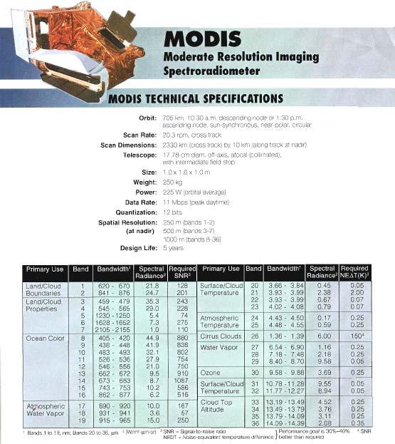
1 ECE 583 Lecture 27 Imaging Visible and Infrared Radiometers Array Detector Imagers Stereo Cloud Hieght & Winds Application

2 Why remote sensing - Much of the atmosphere is inaccessible, at least for routine measurements. From space, only way to provide large enough sample to large-scale view of the Earth system AVHRR SST anomalies Nov 96,97
3 Measurement Requirements for Imaging Radiometers Spatial resolution (pixel size) Number and wavelength of channels Spectral width of wavelength channels Spatial alignment (registration) between wavelength channels Minimum signal measurement accuracy (%) Measurement accuracy of radiance (calibration) Basic Type of Image Scanning Radiometer
4 Pushbroom Imaging Whiskbroom Imaging Grating Spectrometer Pushbroom Imaging
5
6
7
8

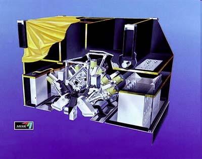
9 Example of MISR Level 2TC data product Hurricane Debby Level 2 Top-of- Atmosphere/Cloud Product This contains measurements of cloud heights and winds, cloud texture, top-ofatmosphere albedos and bidirectional reflectance factors, and other related parameters.
10 Low Earth Orbit Stereo Imagers VISIBLE MISR visible push broom imager, large angle separation tri-angle wind retrieval THERMAL INFRARED ATSR 45 o conical scan, 120 sec image separation, ESA ISIR 8-12 o angle separation, ¼ km resolution, 90 km cross track 260 km orbit height, STS-85 ICIR 10 o angle separation, 0.65 km resolution, 1400 km cross track 820 km orbit height, Proposed
11 Planck s blackbody function The nature of B λ (T) was one of the great findings of the latter part of the 19th century and led to entirely new ways of thinking about energy and matter. Early experimental evidence pointed to two particular characteristics of B λ (T) which simplify calculations. Insert fig 3.1 B B λ λ C C 1 2 2πhc = 5 hc/ λ πλ (e = πλ 5 (e = 2πhc C kt 1 C / λt ) 1) = = = = hc/k = μm K 8 4 W μm 4 4 W μm 4 W nm m 2 cm 4 m 2 2
12 Brightness temperature An important temperature of the physical system, and one different from the thermodynamic temperature in general is the temperature that can be attached photons carrying energy at a fixed wavelength. If the energy of such is I λ, then this temperature is T λ = B -1 (I λ ) = C 2 /{λln[i λ λ 5 π/c 1 +1]} which is referred to as the brightness temperature The brightness temperature of microwave radiation is proportional in a simple way to microwave radiance: Rayleigh Jeans Law λt B(T) kt The spectral brightness temperature of planets and moons
13 IR Stereo Imager Development Global Infrared Stereo Observations by LEO UMAD Imaging Radiometer ISIR Shuttle Hitchhiker Experiment COVIR Instrument Incubator Multi Layer Stereo Retrievals
14 Application: Diurnal Variation in Cloud Height Distribution Diurnal variation is a huge factor for cloud distributions. The best passive retrievals use visible plus IR channels, not possible at night. IR only CO 2 slicing retrievals are limited in resolution. Active sensors, lidar/radar, now measure nadir only. Scanning radar/lidar is high cost and limited to a few 100 km s.

15 Goal 1, Low cost IR cloud imager Goal 2, Stereo Cloud IR in LEO Goal 3, Improved cloud track winds Velden et al., 2005, Bul. AMS The impact of satellite-derived polar winds in global forecast models David A. Santek, CIMSS/Univ. of Wisconsin, Madison, WI The use of Atmospheric Motion Vectors (AMVs) in Numerical Weather Prediction (NWP) models continues to be an important source of information in data sparse regions. These AMVs are derived from a time-sequence of images from geostationary and polar orbiting satellites. NWP centers have documented positive impact on model forecasts not only in regions where the AMVs are measured, but elsewhere as well. One example is the effect of the Moderate Resolution Imaging Spectroradiometer (MODIS) polar winds on forecasts in the middle and subtropical latitudes. Feature-tracked winds derived from a time-sequence of MODIS satellite imagery over the polar regions are routinely input into many operational global numerical models. These NWP centers report that the winds have a positive impact on forecasts not only in the polar regions, but also into mid- and lower-latitudes, especially in 3 to 5 day forecasts. However, the impact differs for different models. Side-by-side experiments were run, with and without MODIS polar winds, using the National Centers for Environmental Prediction's (NCEP) Global Forecast System (GFS) and the Navy's Operational Global Atmospheric Prediction System (NOGAPS) models. Output from these experiments was analyzed by using a combination of model analyses and forecasts, with sophisticated visualization techniques, to determine the impact to global model fields. The differences in these model fields between the GFS and NOGAPS due to the inclusion of the MODIS winds are explained by data thinning, weighting of the wind observations, and characteristics of their respective assimilation systems.


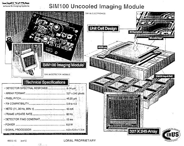
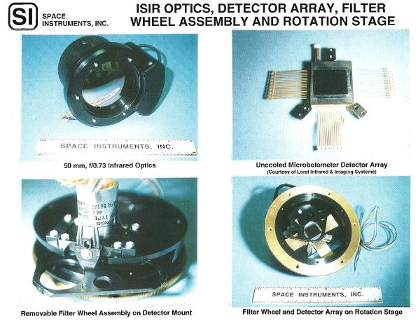
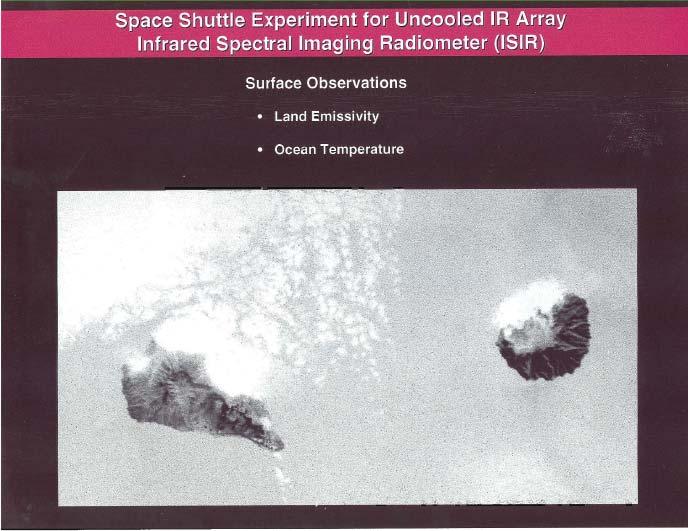
16 Space Shuttle Experiment for Uncooled IR Array Infrared Spectral Imaging Radiometer (ISIR) Objectives: Develop Compact, Low Cost and Rugged Imaging Infrared Cloud Radiometers Test the Application of Uncooled Microbolometer Focal Plane Arrays for Space Borne Imaging Applications Observations For Cloud Science: Obtain Combined Passive/Active Remote Sensing From Joint Shuttle Flight with the SLA Lidar Specifications: Microbolometer array detector eliminates cooling requirements Push broom imaging eliminates mechanical scanning Time delay integration improves NEDT by the square root of the along track detector elements 8, 11, 12 & μm m channels, o K NEDT, 250 m resolution, 82Km swath Microbolometer Array
17

18 Uncooled Microbolometer Array Detector (UMAD) Technology was originally declassified in about The ISIR detector was the second pre-production array produced by Loral Space Systems.
19 Uncooled Microbolometer FPA
20 Altitude ~ 250 km
21 ISIR - Time Delay and Integration (TDI)
22
23 Image Signal as a Function of Lens/Telescope F# P pix (λ) = I(λ) A Ω T sys P = Pixel Signal in Watts F# = L/D A = π D 2 /4 D= Lens Diameter Ω= π (d/l) 2 /4 d = Pixel Diameter L = Focal Length Low F# lens gives brightest imageneeded for higher noise detectors. ISIR Lens: F =.73 Theoretical Minimum F =.6 P pix (λ) = I(λ) (d π / 4F# ) 2 IR imaging radiometer showing refractive telescope and electronics imaging module
24
25
26
27

28

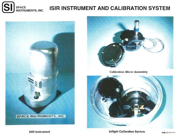
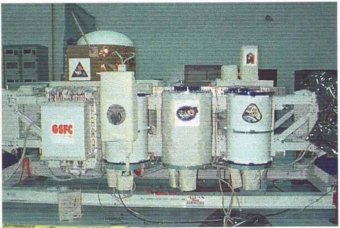
29 ISIR prior to shuttle Hitchhiker bridge installation 8 mm tape drive
30
31

32 87 km swath
33

34 Shuttle Roll Maneuvers with ISIR in Video Camera Mode
")
35 ISIR 10.8 um Channel (Coast of New Jersey) 80 km (50 mi) 145 km (90 mi)

36 ISIR Multispectral Analysis 262 K 281 K Temperature (K) Cirrus Particle Size from IR Split Window Brightness Difference


37 ISIR on STS-85 ISIR SENSOR ASSEMBLY ZnSe WINDOW UPPER END PLATE ADAPTER PLATE RECORDING DEVICE Proved uncooled IR array detectors for space First global multispectral IR data set at 1/4 Km resolution Global cloud science with laser altimeter cloud heights LOWER END PLATE


38 Mars Surface Imager Based On Microbolometer array detector
39 Stereo Height Retrieval Spectral band at moment of image capture Band 1 = 8.6 um Band 3 = 12.0 um degrees FOV ISIR Trajectory Height ~ 260 km ~ 79 km 325 columns ground track at nadir 50 % overlap ~100 rows at sea level ~ 48 km 204 rows Figure 2. Stereo overlap of ISIR image frames acquired at 8.6 and 12 mm roughly 3.5 seconds apart. This gives 50% overlap and complete ground coverage between the two spectral bands calculate the height of any feature in the overlapped region from its measured parallax in pixels as: h = H B δ *θ

40 Lancaster et al., 2003 Stereo Height Retrieval
41 The depth resolution attainable with this method can be expressed in terms of the range-to-baseline ratio and the IFOV. For ratios greater than 30, the depth resolution degenerates to one baseline. The equation below shows the relationship between baseline B; range Z; IFOV, and depth resolution ΔZ/B, for a pixel located at the center of the overlapped region. Simple geometry and trigonometry results in the expression: ΔZ = B tan(arctan( 2 B Z 1 θ B ) ) tan(arctan( 2 2Z θ ) + ) 2 This equation can be used to give height uncertainty in km as a function cloud height h, by replacing the range Z with (H - h). The figure shows the results for an altitude of 266 km, a baseline of 25.9 km and milliradian IFOV. For a single-pixel cloud at 10 km altitude, the height uncertainty would be +/_ 2.3 km (without using a sub-pixel algorithm to search for the parallax giving the best correlation between views) height uncertainty in km ISIR IFO V m rad, altitude 266 km, baseline 25.9 km cloud altitude in km Depth resolution expressed as ± height uncertainty for clouds ranging between sea level and 20 km. Graph is for ISIR stereo imaging.


42 Brightness Temperature (K) Altitude (m) 11500


43 ISIR Cloud Heights from Stereo Analysis Compared to Shuttle Laser Altimeter Cloud Heights Laser Stereo
44 Issues for Stereo Accuracy Measurement physics: Photon penetration / Distributed source function Multi cloud layers Cloud top contrast Cloud motion Instrument issues IFOV and stereo view separation NEDT Height uncertainties driven by measurement physics
45 um Tbr Histogram number of pixels Tbr in K 12 um Tbr Histogram 1000 number of pixels Figure 4. Composite imagery at 8.6 and 12 um, comprised of two frames in each band. Only the regions of overlap are shown. The motion of the ISIR sensor is from the bottom towards the top of the panels Tbr in K Figure 5. Brightness temperature histograms of composite thermal images in Figure 4.
 masks for the stereo pair in Figure 4 are shown, created by assigning a value of 1 to all pixels at or below the indicated brightness temperature, and 0 to all pixels")
46 8.6 micron ROI masks 12 micron ROI masks Figure 6. Binary ROI (region-of-interest) masks for the stereo pair in Figure 4 are shown, created by assigning a value of 1 to all pixels at or below the indicated brightness temperature, and 0 to all pixels above that temperature. The highest clouds are in the masks at the top of the frame, and are arranged in order of increasing temperature, and hence decreasing altitude.

47 Figure 8. Discrete height maps generated from ROI masks and stereo retrieval. The altitudes are tabulated in the table above.

48 Figure um stereo height composite and line plot of stereo heights along nadir column for composite image obtained between 8:17:18:55:31 to 8:17:18:58:04 GMT, or from 90 W, 50 N, to about 60 W, 30 N.

49 Stereo Retrieval Research Multiple Cloud Level Profile Retrieval Objective: Identify common cloud layers for stereo height retrieval Approach: Exploit correlation between infrared T B and cloud height - Define cloud mask based up T B - Identify parallax shift for cloud mask thru pattern matching - Assign retrieved height to all pixels enclosed by mask 2 Result: Stereo height retrieval for multiple cloud layers 3 3 cloud layers Manizade et al., 2005

50 Free Flyer Prototype Development Compact Visible and Infrared Radiometer Optic Bench Visible Camera Assembly 45 cm ½ km resolution from 600km four IR channels between 3.5 and 12.5 um IR detector: Uncooled, microbolometer Focal Plane Array Flip mirror Assembly Internal Blackbody IR Detector Electronics IR Camera Assembly Separate visible and infrared cameras Array detector pushbroom imaging Time Delay and Integration to improve S/N 0.1 o K accuracy at 300 K up to four visible channels between 440 and 860 nm Visible detector: Uncooled, CCD linear array Mass: 20 kg; Power: 35 W
51 COVIR Design Upgrades Move from a filter wheel design to using strip filters 10 μm 10.8 μm 12 μm 3.7 μm Strip Filters Detector Array TEC Cooler Fig. 2 Conceptual drawing of detector assembly Eliminates dead time between filters - Allows for inclusion of 4 th passband with TDI 15 Eliminates possible mechanical failure of the filter wheel. - Provides greater reliability
52 Detector Specifications Infrared 60 pixels 60 pixels 60 pixels 60 pixels Type Uncooled microbolometer FPA Format 327 x 240 Operation Time Delay and Integration Channels 4 Visible Type CCD linear array Format 4 rows of 1x1520 Operation Continuous readout Channels micron channel micron channel micron channel micron channel 320 pixels 240 pixels Figure 3 Microbolometer array with strip filters

53 Optics: Calculations and Trade Studies Analysis: Vignetting calculations for filter strips indicate possible TDI frame rates as a function of F/#: Design Support: Design support for the detector sub-assembly: optical path lengths, element spacings, and materials: sapphire Step A/R Coated Germanium Window 0.5mm { Detector { vignetted region = 3.4 pixels same { vignetted region { vignetted region = 17 pixels Not to Scale } 0.5mm } mm μ Strip Filters Filter Substrate 10 μm 10.8 μm 12 μm DetectorArray TEC Cooler 3.7 μm 15 mils 3-5 mils Ghost Images: calculations to determine guidelines for element spacing: Detector μ μ θ μ L { s { s { s { s s s s

54 IR Optical Prescription Data: F/0.8; Focal length = mm; Aperture = 69 mm A triplet lens design solution: Spotsize Goal = 46 μ; Design Result = 35 μ Encircled energy = 80% IR Lens Mount (Janos):

 0.")
55 Compact Visible and Infrared Radiometer IR Imaging radiometer is built around an uncooled microbolometer array detector (UMAD) Technology benefits: No cooling = low power consumption No cooling = no thermal radiators Focal plane array = Simultaneous 2D imaging Focal plane array = compact, lightweight Focal plane array = stereo imaging Focal plane array showing bandpass filters prior to installing germanium package window Proposed IR Camera Type of Imaging Detector Format Pixel Size Frame Update Rate Telescope Number of channels NEDT Design Parameter Pushbroom Uncooled microbolometer FPA 320x240 pixels um 60 frames/second Refractive, F/0.9 4 (11um, 12umx2, 3.7 um) 0.1 o K IR imaging radiometer showing refractive telescope and electronics imaging module
 5 channel visible and near infrared imaging Combined spatial and")
56 Compact Infrared and Visible Imaging Radiometer -COVIR Small Multispectral Infrared and Visible Imaging Radiometer Cloud and Surface Observations With Combined Spectra and Spatial Imaging Follow on to ISIR-01 experiment on STS-85 Instrument Incubator Project - Engineering Model Development Objective: Moderate resolution (1/2km) 5 channel visible and near infrared imaging Combined spatial and spectral IR imaging Small size and low cost 6

57 Flight Mission Instrument Development Compact Visible and IR Imaging Radiometer Vertical Imaging Cloud Infrared Imager CoVIR IIP Instrument Flight Breadboard 200 km Swath
58 Mission Proposal Design Study SIRICE IR Imaging Radiometer PUSHBROOM SCANNING RADIOMETER IR camera stares nadir or at an angle (fore or aft) Image is sampled sequentially in each of the 3 spectral channels Time Delay and Integration is used to achieve NEDT < 100 mk Image spatial resolution ~ 1.5 km/pixel Two (possibly three) cameras needed to cover 90 o FOV TECHNICAL CHALLENGES: Calibration of the multiple cameras Use of TDI requires spacecraft attitude be controlled to align image motion with 1 dimension of detector array PRACTICAL BENEFITS: Natural mode of operation for 2D array GSFC has developed two of these systems already Most of the technical challenges have been worked out Cross-track direction FOV of sub-mm conical Scanner 1400 km FOV Camera 3 FOV Camera 2 FOV Camera 1 3 IR spectral channels Ground-track of sub-mm conical scanner
59 IRCIR Development Three or four cameras based on COVIR design Each camera covers a 30 degree swath with a max 22.5 fore-aft angle for stereo Basic 1 km resolution with onboard compression and possible stereo processing GSFC PI and management Cost competition build options: - University and GSFC partnership - GSFC in house - Contracted to industry
60 IRCIR Characteristics Signal to Noise Ratio Current UMAD technology: 100 COVIR Spectral Channels NEDT ~ (200/Δλ)(F/#) 2 mk μm For λ~11 um, 300K scene, F/1 SIRICE Requirements: 1 um passband filters Three channels 11 um, 12um, 7 um NEDT < 100 mk Transmission (Percent) Wavelength (nm) SIRICE Results: Wavelength (um) NEDT (mk) (No Averaging) 190 mk 350 mk 243 mk NEDT (mk) (w/ Averaging) <100 mk <100 mk <100 mk Need 3x improvement in SNR Include 10 pixels in TDI average ( 10 ~ 3) Resample single pixel 2x in 0.3 s scan time at 60 fps with <1/10 pixel registration error (SNR increases by 2 ~1.4)


61 IRCIR Global LOE Cloud Imager Mirrors rotate ~45 deg off-nadir to view cloud scene TDI Mirrors rotate ~270 off-nadir to view blackbody calibration source Mirrors rotate ~80 off-nadir to view space for calibration measurement Camera 1 Camera 2 Camera 1 Camera 2 45 deg Camera 3 Camera Resolution (km) Camera 3 Camera 4


62 Infrared Cloud Imaging Radiometer VIRCIR Concept 1400 km Swath Cloud Retrieval 14.4 cm 4 rotating mirrors Servo-motor, capstan drive combo 24.3 cm 14.1 cm 17.3 cm Electronics box Front View 18.3 cm Camera Heads 4 Calibration blackbodies 18.4 cm Camera Heads


63 IRCIR Instrument Concept for Stereo Cloud Track Winds 4 Imaging Arrays With associated Lens assemblies Optics Bench Rotatable Scene Mirror Science IR Cloud Information Stereo Cloud Height Winds (flying in orbit with NPP) Protective Drum Baffle (rotates with Scene Mirror) Cross-track Fields of View IRCIR Provides Full Cross-track Coverage using Four 640 x 480 pixel Uncooled Silicon Micro-bolometer Arrays

64 IRCIR Located on Dedicated Deck Behind SM4 This view of the instrument is rotated about the S/C axis by 90

65 Advanced Technology GOES Imager 101.6cm 75cm Meets all present GOES Imager Requirements Imaging Radiometric Performance Envelope Mass, Power Development Schedule 27 months to flight unit delivery Integration of modern (available) hi-reliability components 81.28cm

.. Preliminary investigation of instrument/spacecraft interface shows no notable concerns.")
66 Rapid Response IR/Visible GOES Meteorological Imager Instrument Characteristics 5 band Step-Staring Imager IFOV: 4 km (IR) /1 km (vis) FOV: 1000 km x 960 km (Present 320x240 LW FPA) Field of Regard: +/- 20 deg. 4-band IR radiometer (~ 7, 11,12, 13.5 μm with uncooled IR FPAs, 3.9 μm with high temperature(190k) HCT FPA) 1-band visible (CCD) Technology and Programmatic Readiness Favorable Accomodation Parameters Technology for all instrument components is sufficiently mature (NASA TRL 7 or higher).. Preliminary investigation of instrument/spacecraft interface shows no notable concerns. Schedule, while aggressive, is consistent with other programs of similar complexity. <90 kg/ 0.4 m 3 / 100 W, and no cryo radiators! 66
67 NESR for 10.8 μm Channel (Standard LW Window) Detector NEP: 3.5 pw/(hz) 1/2 System Transmission: 50% Detector Area: 46x46 μm Solid Angle: (f/1.4) Noise Bandwidth: 7.5 Hz (4) Modulation Frequency: 10 Hz Incoherent Sample Summing Improvement Factor: (20) 1/2 Spectral Pass Band: 88 cm -1 NEP (W/rt Hz) 28 Micron Square Uncooled Bolometer NEP 1.00E E E E E Frequency(Hz) NEP_Thermal NEP_johnson NEP_1/f pix Predicted NESR: <0.07 mw/str/m 2 /cm -1 Required NESR: mw/str/m 2 /cm -1 (200 mk 300K)

68 JEM Attached Payload Modules
OPAL Optical Profiling of the Atmospheric Limb
 OPAL Optical Profiling of the Atmospheric Limb Alan Marchant Chad Fish Erik Stromberg Charles Swenson Jim Peterson OPAL STEADE Mission Storm Time Energy & Dynamics Explorers NASA Mission of Opportunity
CIRiS: Compact Infrared Radiometer in Space August, 2017
 1 CIRiS: Compact Infrared Radiometer in Space August, 2017 David Osterman PI, CIRiS Mission Presented by Hansford Cutlip 10/8/201 7 Overview of the CIRiS instrument and mission The CIRiS instrument is
Some Basic Concepts of Remote Sensing. Lecture 2 August 31, 2005
 Some Basic Concepts of Remote Sensing Lecture 2 August 31, 2005 What is remote sensing Remote Sensing: remote sensing is science of acquiring, processing, and interpreting images and related data that
Satellite/Aircraft Imaging Systems Imaging Sensors Standard scanner designs Image data formats
 CEE 6150: Digital Image Processing 1 Satellite/Aircraft Imaging Systems Imaging Sensors Standard scanner designs Image data formats CEE 6150: Digital Image Processing 2 CEE 6150: Digital Image Processing
Lecture Notes Prepared by Prof. J. Francis Spring Remote Sensing Instruments
 Lecture Notes Prepared by Prof. J. Francis Spring 2005 Remote Sensing Instruments Material from Remote Sensing Instrumentation in Weather Satellites: Systems, Data, and Environmental Applications by Rao,
Wind Imaging Spectrometer and Humidity-sounder (WISH): a Practical NPOESS P3I High-spatial Resolution Sensor
: a Practical NPOESS P3I High-spatial Resolution Sensor") Wind Imaging Spectrometer and Humidity-sounder (WISH): a Practical NPOESS P3I High-spatial Resolution Sensor Jeffery J. Puschell Raytheon Space and Airborne Systems, El Segundo, California Hung-Lung Huang
Wind Imaging Spectrometer and Humidity-sounder (WISH): a Practical NPOESS P3I High-spatial Resolution Sensor Jeffery J. Puschell Raytheon Space and Airborne Systems, El Segundo, California Hung-Lung Huang
LSST All-Sky IR Camera Cloud Monitoring Test Results
 LSST All-Sky IR Camera Cloud Monitoring Test Results Jacques Sebag a, John Andrew a, Dimitri Klebe b, Ronald D. Blatherwick c a National Optical Astronomical Observatory, 950 N Cherry, Tucson AZ 85719
Lecture 6: Multispectral Earth Resource Satellites. The University at Albany Fall 2018 Geography and Planning
 Lecture 6: Multispectral Earth Resource Satellites The University at Albany Fall 2018 Geography and Planning Outline SPOT program and other moderate resolution systems High resolution satellite systems
Kazuhiro TANAKA GCOM project team/jaxa April, 2016
 Kazuhiro TANAKA GCOM project team/jaxa April, 216 @ SPIE Asia-Pacific 216 at New Dehli, India 1 http://suzaku.eorc.jaxa.jp/gcom_c/index_j.html GCOM mission and satellites SGLI specification and IRS overview
NON-PHOTOGRAPHIC SYSTEMS: Multispectral Scanners Medium and coarse resolution sensor comparisons: Landsat, SPOT, AVHRR and MODIS
 NON-PHOTOGRAPHIC SYSTEMS: Multispectral Scanners Medium and coarse resolution sensor comparisons: Landsat, SPOT, AVHRR and MODIS CLASSIFICATION OF NONPHOTOGRAPHIC REMOTE SENSORS PASSIVE ACTIVE DIGITAL
Philpot & Philipson: Remote Sensing Fundamentals Scanners 8.1 W.D. Philpot, Cornell University, Fall 2015
 Philpot & Philipson: Remote Sensing Fundamentals Scanners 8.1 8. SCANNERS 8.1 General Scanners are scanning radiometers which, when operated from an airborne or spaceborne platform, image the terrain in
Japanese Advanced Meteorological Imager: A Next Generation GEO Imager for MTSAT-1R
 Japanese Advanced Meteorological Imager: A Next Generation GEO Imager for MTSAT-1R Jeffery J. Puschell 1 Raytheon Electronic Systems, Santa Barbara Remote Sensing ABSTRACT The Japanese Advanced Meteorological
Hyperspectral goes to UAV and thermal
 Hyperspectral goes to UAV and thermal Timo Hyvärinen, Hannu Holma and Esko Herrala SPECIM, Spectral Imaging Ltd, Finland www.specim.fi Outline Roadmap to more compact, higher performance hyperspectral
Chapter 8. Remote sensing
 1. Remote sensing 8.1 Introduction 8.2 Remote sensing 8.3 Resolution 8.4 Landsat 8.5 Geostationary satellites GOES 8.1 Introduction What is remote sensing? One can describe remote sensing in different
THE SPACE TECHNOLOGY RESEARCH VEHICLE 2 MEDIUM WAVE INFRA RED IMAGER
 THE SPACE TECHNOLOGY RESEARCH VEHICLE 2 MEDIUM WAVE INFRA RED IMAGER S J Cawley, S Murphy, A Willig and P S Godfree Space Department The Defence Evaluation and Research Agency Farnborough United Kingdom
746A27 Remote Sensing and GIS. Multi spectral, thermal and hyper spectral sensing and usage
 746A27 Remote Sensing and GIS Lecture 3 Multi spectral, thermal and hyper spectral sensing and usage Chandan Roy Guest Lecturer Department of Computer and Information Science Linköping University Multi
NASTER System Definition Proposal
 Remote Sensing Team NASTER System Definition Proposal All rights reserved. - 7/14/03 Page 1 Overview Review and comment the mid-ir requirements Presentation of ABB s current platform technology Proposed
Compact High Resolution Imaging Spectrometer (CHRIS) siraelectro-optics
 siraelectro-optics") Compact High Resolution Imaging Spectrometer (CHRIS) Mike Cutter (Mike_Cutter@siraeo.co.uk) Summary CHRIS Instrument Design Instrument Specification & Performance Operating Modes Calibration Plan Data
Compact High Resolution Imaging Spectrometer (CHRIS) Mike Cutter (Mike_Cutter@siraeo.co.uk) Summary CHRIS Instrument Design Instrument Specification & Performance Operating Modes Calibration Plan Data
NIRST, a satellite based IR instrument for fire and sea surface temperature measurement
 NIRST, a satellite based IR instrument for fire and sea surface temperature measurement Hugo Marraco a and Linh Ngo Phong b a Comisión Nacional de Actividades Espaciales, Paseo Colón 751, C1063ACH Buenos
Passive Microwave Sensors LIDAR Remote Sensing Laser Altimetry. 28 April 2003
 Passive Microwave Sensors LIDAR Remote Sensing Laser Altimetry 28 April 2003 Outline Passive Microwave Radiometry Rayleigh-Jeans approximation Brightness temperature Emissivity and dielectric constant
Compact Dual Field-of-View Telescope for Small Satellite Payloads
 Compact Dual Field-of-View Telescope for Small Satellite Payloads James C. Peterson Space Dynamics Laboratory 1695 North Research Park Way, North Logan, UT 84341; 435-797-4624 Jim.Peterson@sdl.usu.edu
The Global Imager (GLI)
") The Global Imager (GLI) Launch : Dec.14, 2002 Initial check out : to Apr.14, 2003 (~L+4) First image: Jan.25, 2003 Second image: Feb.6 and 7, 2003 Calibration and validation : to Dec.14, 2003(~L+4) for
The Global Imager (GLI) Launch : Dec.14, 2002 Initial check out : to Apr.14, 2003 (~L+4) First image: Jan.25, 2003 Second image: Feb.6 and 7, 2003 Calibration and validation : to Dec.14, 2003(~L+4) for
Remote Sensing 1 Principles of visible and radar remote sensing & sensors
 Remote Sensing 1 Principles of visible and radar remote sensing & sensors Nick Barrand School of Geography, Earth & Environmental Sciences University of Birmingham, UK Field glaciologist collecting data
Remote Sensing Exam 2 Study Guide
 Remote Sensing Exam 2 Study Guide Resolution Analog to digital Instantaneous field of view (IFOV) f ( cone angle of optical system ) Everything in that area contributes to spectral response mixels Sampling
Chapter 5 Nadir looking UV measurement.
 Chapter 5 Nadir looking UV measurement. Part-II: UV polychromator instrumentation and measurements -A high SNR and robust polychromator using a 1D array detector- UV spectrometers onboard satellites have
Atmospheric interactions; Aerial Photography; Imaging systems; Intro to Spectroscopy Week #3: September 12, 2018
 GEOL 1460/2461 Ramsey Introduction/Advanced Remote Sensing Fall, 2018 Atmospheric interactions; Aerial Photography; Imaging systems; Intro to Spectroscopy Week #3: September 12, 2018 I. Quick Review from
Lecture 2. Electromagnetic radiation principles. Units, image resolutions.
 NRMT 2270, Photogrammetry/Remote Sensing Lecture 2 Electromagnetic radiation principles. Units, image resolutions. Tomislav Sapic GIS Technologist Faculty of Natural Resources Management Lakehead University
The Sounding Instruments on Second Generation of Chinese Meteorological Satellite FY-3
 The Sounding Instruments on Second Generation of Chinese Meteorological Satellite FY-3 DONG Chaohua ZHANG Wenjian National Satellite Meteorological Center China Meteorological Administration Beijing 100081,
Radiometric performance of Second Generation Global Imager (SGLI) using integrating sphere
 using integrating sphere") Radiometric performance of Second Generation Global Imager (SGLI) using integrating sphere Taichiro Hashiguchi, Yoshihiko Okamura, Kazuhiro Tanaka, Yukinori Nakajima Japan Aerospace Exploration Agency
Radiometric performance of Second Generation Global Imager (SGLI) using integrating sphere Taichiro Hashiguchi, Yoshihiko Okamura, Kazuhiro Tanaka, Yukinori Nakajima Japan Aerospace Exploration Agency
Advanced Optical Satellite (ALOS-3) Overviews
 Overviews") K&C Science Team meeting #24 Tokyo, Japan, January 29-31, 2018 Advanced Optical Satellite (ALOS-3) Overviews January 30, 2018 Takeo Tadono 1, Hidenori Watarai 1, Ayano Oka 1, Yousei Mizukami 1, Junichi
K&C Science Team meeting #24 Tokyo, Japan, January 29-31, 2018 Advanced Optical Satellite (ALOS-3) Overviews January 30, 2018 Takeo Tadono 1, Hidenori Watarai 1, Ayano Oka 1, Yousei Mizukami 1, Junichi
Remote Sensing Platforms
 Types of Platforms Lighter-than-air Remote Sensing Platforms Free floating balloons Restricted by atmospheric conditions Used to acquire meteorological/atmospheric data Blimps/dirigibles Major role - news
9/12/2011. Training Course Remote Sensing Basic Theory & Image Processing Methods September 2011
 Training Course Remote Sensing Basic Theory & Image Processing Methods 19 23 September 2011 Popular Remote Sensing Sensors & their Selection Michiel Damen (September 2011) damen@itc.nl 1 Overview Low resolution
Congress Best Paper Award
 Congress Best Paper Award Preprints of the 3rd IFAC Conference on Mechatronic Systems - Mechatronics 2004, 6-8 September 2004, Sydney, Australia, pp.547-552. OPTO-MECHATRONIC IMAE STABILIZATION FOR A COMPACT
Microbolometers for Infrared Imaging and the 2012 Student Infrared Imaging Competition
 Microbolometers for Infrared Imaging and the 2012 Student Infrared Imaging Competition George D Skidmore, PhD Principal Scientist DRS Technologies RSTA Group Competition Flyer 2 Passive Night Vision Technologies
Camera Case Study: HiSCI à now CaSSIS (Colour and Stereo Surface Imaging System)
") Camera Case Study: HiSCI à now CaSSIS (Colour and Stereo Surface Imaging System) A camera for ESA s 2016 ExoMars Trace Gas Orbiter: h
Camera Case Study: HiSCI à now CaSSIS (Colour and Stereo Surface Imaging System) A camera for ESA s 2016 ExoMars Trace Gas Orbiter: h
Development of the Compact InfraRed Camera (CIRC) for wildfire detection
 for wildfire detection") Development of the Compact InfraRed Camera (CIRC) for wildfire detection Haruyoshi Katayama a*, Masataka Naitoh a, Masahiro Suganuma a, Masatomo Harada a, Yoshihiko Okamura a, Yoshio Tange a, and Koji
Development of the Compact InfraRed Camera (CIRC) for wildfire detection Haruyoshi Katayama a*, Masataka Naitoh a, Masahiro Suganuma a, Masatomo Harada a, Yoshihiko Okamura a, Yoshio Tange a, and Koji
remote sensing? What are the remote sensing principles behind these Definition
 Introduction to remote sensing: Content (1/2) Definition: photogrammetry and remote sensing (PRS) Radiation sources: solar radiation (passive optical RS) earth emission (passive microwave or thermal infrared
METimage an innovative imaging radiometer for Post-EPS
 METimage an innovative imaging radiometer for Post-EPS Dr. Christian Brüns 1, Dr. Matthias Alpers 1, Dr. Alexander Pillukat 2 1 DLR German Space Agency, Königswinterer Straße 522-524, D-53227 Bonn, Germany
The studies began when the Tiros satellites (1960) provided man s first synoptic view of the Earth s weather systems.
 provided man s first synoptic view of the Earth s weather systems.") Remote sensing of the Earth from orbital altitudes was recognized in the mid-1960 s as a potential technique for obtaining information important for the effective use and conservation of natural resources.
Remote sensing of the Earth from orbital altitudes was recognized in the mid-1960 s as a potential technique for obtaining information important for the effective use and conservation of natural resources.
SR-5000N design: spectroradiometer's new performance improvements in FOV response uniformity (flatness) scan speed and other important features
 scan speed and other important features") SR-5000N design: spectroradiometer's new performance improvements in FOV response uniformity (flatness) scan speed and other important features Dario Cabib *, Shmuel Shapira, Moshe Lavi, Amir Gil and Uri
SR-5000N design: spectroradiometer's new performance improvements in FOV response uniformity (flatness) scan speed and other important features Dario Cabib *, Shmuel Shapira, Moshe Lavi, Amir Gil and Uri
3/31/03. ESM 266: Introduction 1. Observations from space. Remote Sensing: The Major Source for Large-Scale Environmental Information
 Remote Sensing: The Major Source for Large-Scale Environmental Information Jeff Dozier Observations from space Sun-synchronous polar orbits Global coverage, fixed crossing, repeat sampling Typical altitude
Observational Astronomy
 Observational Astronomy Instruments The telescope- instruments combination forms a tightly coupled system: Telescope = collecting photons and forming an image Instruments = registering and analyzing the
SIRAS-G, The Spaceborne Infrared Atmospheric Sounder: The Potential for High-Resolution IR Imaging Spectrometry From Geosynchronous Orbit
 SIRAS-G, The Spaceborne Infrared Atmospheric Sounder: The Potential for High-Resolution IR Imaging Spectrometry From Geosynchronous Orbit Thomas U. Kampe Ball Aerospace & Technologies Corp. 1600 Commerce
Japanese Advanced Meteorological Imager (JAMI): Design, Characterization and Expected On-Orbit Performance
: Design, Characterization and Expected On-Orbit Performance") Japanese dvanced Meteorological Imager (JMI): Design, Characterization and Expected On-Orbit Performance Jeffery J. Puschell *, Howard. Lowe, James Jeter, Steven Kus, Roderic Osgood, W. Todd Hurt, David
Japanese dvanced Meteorological Imager (JMI): Design, Characterization and Expected On-Orbit Performance Jeffery J. Puschell *, Howard. Lowe, James Jeter, Steven Kus, Roderic Osgood, W. Todd Hurt, David
US Commercial Imaging Satellites
 US Commercial Imaging Satellites In the early 1990s, Russia began selling 2-meter resolution product from its archives of collected spy satellite imagery. Some of this product was down-sampled to provide
LE/ESSE Payload Design
 LE/ESSE4360 - Payload Design 3.2 Spacecraft Sensors Introduction to Sensors Earth, Moon, Mars, and Beyond Dr. Jinjun Shan, Professor of Space Engineering Department of Earth and Space Science and Engineering
Photogrammetry. Lecture 4 September 7, 2005
 Photogrammetry Lecture 4 September 7, 2005 What is Photogrammetry Photogrammetry is the art and science of making accurate measurements by means of aerial photography: Analog photogrammetry (using films:
MSPI: The Multiangle Spectro-Polarimetric Imager
 MSPI: The Multiangle Spectro-Polarimetric Imager I. Summary Russell A. Chipman Professor, College of Optical Sciences University of Arizona (520) 626-9435 rchipman@optics.arizona.edu The Multiangle SpectroPolarimetric
AVHRR/3 Operational Calibration
 AVHRR/3 Operational Calibration Jörg Ackermann, Remote Sensing and Products Division 1 Workshop`Radiometric Calibration for European Missions, 30/31 Aug. 2017`,Frascati (EUM/RSP/VWG/17/936014) AVHRR/3
AMIPAS. Advanced Michelson Interferometer for Passive Atmosphere Sounding. Concepts and Technology for Future Atmospheric Chemistry Sensors
 Earth Observation, Navigation & Science Concepts and Technology for Future Atmospheric Chemistry Sensors AMIPAS Advanced Michelson Interferometer for Passive Atmosphere Sounding Markus Melf, Winfried Posselt,
Compact Multispectral and Hyperspectral Imagers based on a Wide Field of View TMA
 Compact Multispectral and Hyperspectral Imagers based on a Wide Field of View TMA M. Taccola (AOES),S. Grabarnik (AOES), L. Maresi (ESA/ESTEC), V. Moreau (AMOS), L. de Vos (OIP), Y. Versluys (OIP), G.
Dario Cabib, Amir Gil, Moshe Lavi. Edinburgh April 11, 2011
 New LWIR Spectral Imager with uncooled array SI-LWIR LWIR-UC Dario Cabib, Amir Gil, Moshe Lavi Edinburgh April 11, 2011 Contents BACKGROUND AND HISTORY RATIONALE FOR UNCOOLED CAMERA BASED SPECTRAL IMAGER
NOAA EON-IR CubeSat Study for Operational Infrared Soundings
 NOAA EON-IR CubeSat Study for Operational Infrared Soundings Dan Mamula National Oceanic and Atmospheric Administration National Environmental Satellite, Data, and Information Service Office of Project,
9/12/2011. Training Course Remote Sensing Basic Theory & Image Processing Methods September 2011
 Training Course Remote Sensing Basic Theory & Image Processing Methods 19 23 September 2011 Remote Sensing Platforms Michiel Damen (September 2011) damen@itc.nl 1 Overview Platforms & missions aerial surveys
Japanese Advanced Meteorological Imager
 Japanese Advanced Meteorological Imager Jeffery J. Puschell Raytheon Space and Airborne Systems 2000 East El Segundo Boulevard, EO/E01/C150 El Segundo, CA 90245-0902 UNITED STATES OF AMERICA Abstract:
Introduction to Remote Sensing Fundamentals of Satellite Remote Sensing. Mads Olander Rasmussen
 Introduction to Remote Sensing Fundamentals of Satellite Remote Sensing Mads Olander Rasmussen (mora@dhi-gras.com) 01. Introduction to Remote Sensing DHI What is remote sensing? the art, science, and technology
Cross Track Infrared Sounder (CrIS) Flight Model 1 Test Results
 Flight Model 1 Test Results") May 6, 2009 Ronald Glumb, Joseph P. Predina, Robert Hookman, Chris Ellsworth, John Bobilya, Steve Wells, Lawrence Suwinski, Rebecca Frain, and Larry Crawford For Publication at the ASS-FTS14 Conference
May 6, 2009 Ronald Glumb, Joseph P. Predina, Robert Hookman, Chris Ellsworth, John Bobilya, Steve Wells, Lawrence Suwinski, Rebecca Frain, and Larry Crawford For Publication at the ASS-FTS14 Conference
On the use of water color missions for lakes in 2021
 Lakes and Climate: The Role of Remote Sensing June 01-02, 2017 On the use of water color missions for lakes in 2021 Cédric G. Fichot Department of Earth and Environment 1 Overview 1. Past and still-ongoing
ALISEO: an Imaging Interferometer for Earth Observation
 ALISEO: an Imaging Interferometer for Earth Observation A. Barducci, F. Castagnoli, G. Castellini, D. Guzzi, C. Lastri, P. Marcoionni, I. Pippi CNR IFAC Sesto Fiorentino, ITALY ASSFTS14 Firenze - May 6-8,
Sentinel-2 Products and Algorithms
 Sentinel-2 Products and Algorithms Ferran Gascon (Sentinel-2 Data Quality Manager) Workshop Preparations for Sentinel 2 in Europe, Oslo 26 November 2014 Sentinel-2 Mission Mission Overview Products and
Govt. Engineering College Jhalawar Model Question Paper Subject- Remote Sensing & GIS
 Govt. Engineering College Jhalawar Model Question Paper Subject- Remote Sensing & GIS Time: Max. Marks: Q1. What is remote Sensing? Explain the basic components of a Remote Sensing system. Q2. What is
746A27 Remote Sensing and GIS
 746A27 Remote Sensing and GIS Lecture 1 Concepts of remote sensing and Basic principle of Photogrammetry Chandan Roy Guest Lecturer Department of Computer and Information Science Linköping University What
Hyper-spectral, UHD imaging NANO-SAT formations or HAPS to detect, identify, geolocate and track; CBRN gases, fuel vapors and other substances
 Hyper-spectral, UHD imaging NANO-SAT formations or HAPS to detect, identify, geolocate and track; CBRN gases, fuel vapors and other substances Arnold Kravitz 8/3/2018 Patent Pending US/62544811 1 HSI and
Low Cost Earth Sensor based on Oxygen Airglow
 Assessment Executive Summary Date : 16.06.2008 Page: 1 of 7 Low Cost Earth Sensor based on Oxygen Airglow Executive Summary Prepared by: H. Shea EPFL LMTS herbert.shea@epfl.ch EPFL Lausanne Switzerland
SATELLITE OCEANOGRAPHY
 SATELLITE OCEANOGRAPHY An Introduction for Oceanographers and Remote-sensing Scientists I. S. Robinson Lecturer in Physical Oceanography Department of Oceanography University of Southampton JOHN WILEY
RADIATION BUDGET INSTRUMENT (RBI): FINAL DESIGN AND INITIAL EDU TEST RESULTS
: FINAL DESIGN AND INITIAL EDU TEST RESULTS") Place image here (10 x 3.5 ) RADIATION BUDGET INSTRUMENT (RBI): FINAL DESIGN AND INITIAL EDU TEST RESULTS RONALD GLUMB, JAY OVERBECK, CHRISTOPHER LIETZKE, JOHN FORSYTHE, ALAN BELL, AND JASON MILLER NON-EXPORT
Place image here (10 x 3.5 ) RADIATION BUDGET INSTRUMENT (RBI): FINAL DESIGN AND INITIAL EDU TEST RESULTS RONALD GLUMB, JAY OVERBECK, CHRISTOPHER LIETZKE, JOHN FORSYTHE, ALAN BELL, AND JASON MILLER NON-EXPORT
On-Orbit Radiometric Performance of the Landsat 8 Thermal Infrared Sensor. External Editors: James C. Storey, Ron Morfitt and Prasad S.
 Remote Sens. 2014, 6, 11753-11769; doi:10.3390/rs61211753 OPEN ACCESS remote sensing ISSN 2072-4292 www.mdpi.com/journal/remotesensing Article On-Orbit Radiometric Performance of the Landsat 8 Thermal
John P. Stevens HS: Remote Sensing Test
 Name(s): Date: Team name: John P. Stevens HS: Remote Sensing Test 1 Scoring: Part I - /18 Part II - /40 Part III - /16 Part IV - /14 Part V - /93 Total: /181 2 I. History (3 pts. each) 1. What is the name
Important Missions. weather forecasting and monitoring communication navigation military earth resource observation LANDSAT SEASAT SPOT IRS
 Fundamentals of Remote Sensing Pranjit Kr. Sarma, Ph.D. Assistant Professor Department of Geography Mangaldai College Email: prangis@gmail.com Ph. No +91 94357 04398 Remote Sensing Remote sensing is defined
CaSSIS. Colour and Stereo Surface Imaging System. L. Gambicorti & CaSSIS team
 CaSSIS Colour and Stereo Surface Imaging System & CaSSIS team CaSSIS on Exomars TGO l l Introduction CaSSIS: stereo-colour camera Telescope and Optical configuration Best focus on ground CaSSIS integration
Large format 17µm high-end VOx µ-bolometer infrared detector
 Large format 17µm high-end VOx µ-bolometer infrared detector U. Mizrahi, N. Argaman, S. Elkind, A. Giladi, Y. Hirsh, M. Labilov, I. Pivnik, N. Shiloah, M. Singer, A. Tuito*, M. Ben-Ezra*, I. Shtrichman
Remote Sensing. Division C. Written Exam
 Remote Sensing Division C Written Exam Team Name: Team #: Team Members: _ Score: /132 A. Matching (10 points) 1. Nadir 2. Albedo 3. Diffraction 4. Refraction 5. Spatial Resolution 6. Temporal Resolution
Detectors that cover a dynamic range of more than 1 million in several dimensions
 Detectors that cover a dynamic range of more than 1 million in several dimensions Detectors for Astronomy Workshop Garching, Germany 10 October 2009 James W. Beletic Teledyne Providing the best images
Workshop on Practical Applications of MODIS Data in Australia
 Workshop on Practical Applications of MODIS Data in Australia Leeuwin Centre, Floreat WA November 26-29, 2002 Liam Gumley Space Science and Engineering Center University of Wisconsin-Madison Introduction
Advanced Radiometer for Sea Surface Temperature Observations
 Advanced Radiometer for Sea Surface Temperature Observations Harp Technologies Oy: J. Kainulainen, J. Uusitalo, J. Lahtinen TERMA A/S: M. Hansen, M. Pedersen Finnish Remote Sensing Days 2014 Finnish Meteorological
CCDs for Earth Observation James Endicott 1 st September th UK China Workshop on Space Science and Technology, Milton Keynes, UK
 CCDs for Earth Observation James Endicott 1 st September 2011 7 th UK China Workshop on Space Science and Technology, Milton Keynes, UK Introduction What is this talk all about? e2v sensors in spectrometers
Fundamentals of Remote Sensing
 Climate Variability, Hydrology, and Flooding Fundamentals of Remote Sensing May 19-22, 2015 GEO-Latin American & Caribbean Water Cycle Capacity Building Workshop Cartagena, Colombia 1 Objective To provide
Part I. The Importance of Image Registration for Remote Sensing
 Part I The Importance of Image Registration for Remote Sensing 1 Introduction jacqueline le moigne, nathan s. netanyahu, and roger d. eastman Despite the importance of image registration to data integration
Sub-Mesoscale Imaging of the Ionosphere with SMAP
 Sub-Mesoscale Imaging of the Ionosphere with SMAP Tony Freeman Xiaoqing Pi Xiaoyan Zhou CEOS Workshop, ASF, Fairbanks, Alaska, December 2009 1 Soil Moisture Active-Passive (SMAP) Overview Baseline Mission
The Advanced Along-Track Scanning Radiometer (AATSR) Mission Status and Early Results
 Mission Status and Early Results") The Advanced Along-Track Scanning Radiometer (AATSR) Mission Status and Early Results M. C. Edwards (University of Leicester, UK) D. Llewellyn-Jones (University of Leicester, UK) D. L. Smith (Rutherford
The Advanced Along-Track Scanning Radiometer (AATSR) Mission Status and Early Results M. C. Edwards (University of Leicester, UK) D. Llewellyn-Jones (University of Leicester, UK) D. L. Smith (Rutherford
Microwave Remote Sensing (1)
") Microwave Remote Sensing (1) Microwave sensing encompasses both active and passive forms of remote sensing. The microwave portion of the spectrum covers the range from approximately 1cm to 1m in wavelength.
Microwave Remote Sensing (1) Microwave sensing encompasses both active and passive forms of remote sensing. The microwave portion of the spectrum covers the range from approximately 1cm to 1m in wavelength.
Consumer digital CCD cameras
 CAMERAS Consumer digital CCD cameras Leica RC-30 Aerial Cameras Zeiss RMK Zeiss RMK in aircraft Vexcel UltraCam Digital (note multiple apertures Lenses for Leica RC-30. Many elements needed to minimize
RECONNAISSANCE PAYLOADS FOR RESPONSIVE SPACE
 3rd Responsive Space Conference RS3-2005-5004 RECONNAISSANCE PAYLOADS FOR RESPONSIVE SPACE Charles Cox Stanley Kishner Richard Whittlesey Goodrich Optical and Space Systems Division Danbury, CT Frederick
Japan's Greenhouse Gases Observation from Space
 1 Workshop on EC CEOS Priority on GHG Monitoring Japan's Greenhouse Gases Observation from Space 18 June, 2018@Ispra, Italy Masakatsu NAKAJIMA Japan Aerospace Exploration Agency Development and Operation
Mission requirements and satellite overview
 Mission requirements and satellite overview E. BOUSSARIE 1 Dual concept Users need Defence needs Fulfil the Defence needs on confidentiality and security Civilian needs Fulfillment of the different needs
Current and Future Meteorological Satellite Program of China
 Current and Future Meteorological Satellite Program of China ZHANG Wenjian, DONG Chaohua XU Jianmin, YANG Jun China Meteorological Administration May 30, 2005 Beijing, CHINA Outline of the Presentation
MERIS US Workshop. Instrument Overview. Steven Delwart
 MERIS US Workshop Instrument Overview Steven Delwart ENVISAT Acknowledgement To the ENVISAT Team & MERIS Instrument Engineers Jean-Loup Bezy George Gourmelon ENVISAT- MERIS 120M 200 Kg 1m 3 175 W MERIS
Typical technical and operational characteristics of Earth exploration-satellite service (passive) systems using allocations between 1.
 systems using allocations between 1.") Recommendation ITU-R RS.1861 (01/2010) Typical technical and operational characteristics of Earth exploration-satellite service (passive) systems using allocations between 1.4 and 275 GHz RS Series Remote
Recommendation ITU-R RS.1861 (01/2010) Typical technical and operational characteristics of Earth exploration-satellite service (passive) systems using allocations between 1.4 and 275 GHz RS Series Remote
Multispectral Scanners for Wildland Fire Assessment NASA Ames Research Center Earth Science Division. Bruce Coffland U.C.
 Multispectral Scanners for Wildland Fire Assessment NASA Earth Science Division Bruce Coffland U.C. Santa Cruz Slide Fire Burn Area (MASTER/B200) R 2.2um G 0.87um B 0.65um Airborne Science & Technology
METimage Calibration & Performance Verification. Xavier Gnata ICSO 2016
 METimage Calibration & Performance Verification Xavier Gnata ICSO 2016 METimage factsheet Mission Passive imaging radiometer (multi-spectral) 20 spectral channels (443 13.345nm) Global coverage within
Remote Sensing of the Environment An Earth Resource Perspective John R. Jensen Second Edition
 Remote Sensing of the Environment An Earth Resource Perspective John R. Jensen Second Edition Pearson Education Limited Edinburgh Gate Harlow Essex CM20 2JE England and Associated Companies throughout
EPS Bridge Low-Cost Satellite
 EPS Bridge Low-Cost Satellite Results of a Concept Study being performed for Dr. Hendrik Lübberstedt OHB-System AG OpSE Workshop Walberberg 8th November 2005 EPS Bridge Key System Requirements Minimum
Optical Correlator for Image Motion Compensation in the Focal Plane of a Satellite Camera
 15 th IFAC Symposium on Automatic Control in Aerospace Bologna, September 6, 2001 Optical Correlator for Image Motion Compensation in the Focal Plane of a Satellite Camera K. Janschek, V. Tchernykh, -
MR-i. Hyperspectral Imaging FT-Spectroradiometers Radiometric Accuracy for Infrared Signature Measurements
 MR-i Hyperspectral Imaging FT-Spectroradiometers Radiometric Accuracy for Infrared Signature Measurements FT-IR Spectroradiometry Applications Spectroradiometry applications From scientific research to
Outline. Introduction. Introduction: Film Emulsions. Sensor Systems. Types of Remote Sensing. A/Prof Linlin Ge. Photographic systems (cf(
 GMAT x600 Remote Sensing / Earth Observation Types of Sensor Systems (1) Outline Image Sensor Systems (i) Line Scanning Sensor Systems (passive) (ii) Array Sensor Systems (passive) (iii) Antenna Radar
Remote Sensing Platforms
 Remote Sensing Platforms Remote Sensing Platforms - Introduction Allow observer and/or sensor to be above the target/phenomena of interest Two primary categories Aircraft Spacecraft Each type offers different
Int n r t o r d o u d c u ti t on o n to t o Remote Sensing
 Introduction to Remote Sensing Definition of Remote Sensing Remote sensing refers to the activities of recording/observing/perceiving(sensing)objects or events at far away (remote) places. In remote sensing,
NIRCam optical calibration sources
 NIRCam optical calibration sources Stephen F. Somerstein, Glen D. Truong Lockheed Martin Advanced Technology Center, D/ABDS, B/201 3251 Hanover St., Palo Alto, CA 94304-1187 ABSTRACT The Near Infrared
REMOTE SENSING INTERPRETATION
 REMOTE SENSING INTERPRETATION Jan Clevers Centre for Geo-Information - WU Remote Sensing --> RS Sensor at a distance EARTH OBSERVATION EM energy Earth RS is a tool; one of the sources of information! 1