Vessel Visualization using Curvicircular Feature Aggregation Evaluation
|
|
|
- Randell Black
- 5 years ago
- Views:
Transcription
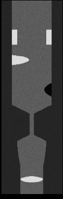
1 Vessel Visualization using Curvicircular Feature Aggregation Evaluation Name: Date: The aim of this questionnaire is the evaluation of a visualization technique, called Curvicircular Feature Aggregation (CFA). This approach is an extension of the commonly used method Maximum Intensity Projection (). The difference lies in the way how the data is sampled along a given centerline of a vessel. It can be seen as a around a vessel. determines the maximum of the data along a viewing ray and shows this in the final image, whereas CFA samples the data along circular rays around the centerline of a vessel, as shown in the illustration on the bottom of this page. Different methods can be applied to these circular rays, such as determining the maximum or the minimum data value along them. The motivation behind this approach is the aggregation of features into a single image. It can be seen as combination of multiple Curved Planar Reformation (CPR) images of different viewing angles. This is suited for inspecting vessels, since they have a cylindrical shape. The circular rays start at a centerline point and go around the vessel. In the following pages, we evaluate the advantages and disadvantages of this proposed technique, compared to CPR and. In every subsequent question, you can only check one answer. The follow main questions will be investigated throughout this questionnaire. Q1 Location of a pathology Q2 Size of a pathology Q3 Centeredness of the centerline of a vessel 3D Sampling Result Image ω δ MINIP b 3 Aggregation ray profile 1 vessel ray profile 2 centerline ray profile 3 a cross-section circular rays c maximum minimum d radii of circles centerline 1
2 2


 will be presented based on the phantom data set.")
.")
 on its left side and the minimum data value (Minimum")
3 1 Phantom Data A phantom data set showing a vessel with several pathologies should give an overview and demonstration of, CPR and CFA. It covers the following important cases that need to be evaluated throughout this questionnaire: 1. Small calcification 2. A ring-like calcification around the whole vessel wall 3. Big calcification 4. Soft plaque 5. Stenosis 6. Non-centered centerline with small calcification The following figure shows a 3D visualization of the phantom data set with axial slice images on the left, corresponding to the above mentioned cases, apart from the stenosis. small calcification calcification on the whole vessel wall big calcification soft plaque stenosis small calcification, not centered centerline center point One the next page, a comparison of Maximum Intensity Projection (), Curved Planar Reformation (CPR) and Curvicircular Feature Aggregation (CFA) will be presented based on the phantom data set. On the top-left, the image is shown, where the centerline is highlighted in green. The top-right images show the axial slices of the important cases given above (except the stenosis). Several CPR images are presented in the middle, from 90 to 90 with a step of 9 and 20 images in total. The bottom image demonstrates the CFA with showing the maximum data value () on its left side and the minimum data value (Minimum Intensity Projection (MINIP)) on its right side. These two sides are delineated by a thin black line. Please answer the questions on page five according to these images. If you have any comments or remarks, please fill them in below the questions. 3
 (2)")
 CPR")


4 Slices (1) (2) (3) (4) (6) CPR CFA left: right: MINIP 4
5 General 1 Which method depicts the small calcification (1) best? 2 Which method depicts the ring-like calcification (2) best? 3 Which method depicts the big calcification (3) best? 4 Which method depicts the soft plaque (4) best? 5 Which method depicts the stenosis (5) best? 6 Which method depicts the non-centered small calcification (6) best? 7 Which method do you prefer solely for investigating pathologies? 8 Which method do you prefer together with axial images for investigating pathologies? 9 Which method is the least intuitive one? 10 Which method is the most intuitive one? Size of pathology 11 Is it helpful to know the size of a pathology? 12 Is it required to know the size of a pathology? 13 Which method depicts the size of a pathology best? 14 Which method do you prefer together with axial images to determine the size? Location of pathology 15 Is it helpful to know the location of a pathology regarding the vessel diameter? 16 Is it required to know the location of a pathology regarding the vessel diameter? 17 Which method depicts the location of a pathology best? 18 Which method do you prefer together with axial images to determine the location? Centeredness of centerline 19 Is it helpful to visually perceive if a centerline is not centered properly? 20 Is it required to visually perceive if a centerline is not centered properly? 21 Which method depicts the non-centeredness of the centerline best? 22 Which method do you prefer together with axial images to verify and correct this? Remarks: 5


 are")


6 2 Vessel Stenosis The following images show a stenosis pointed out by white arrows. CPR images (from 90 to 90, 10 images) are shown on the left side, top-right a and bottom-right a CFA. The CFA shows the maximum () on its left side and the minimum (MINIP) on the right. The axial slice images show on top the start of the stenosis, in the middle the center of the stenosis and on the bottom the end. The vessel of interest is pointed out with the arrows. Please answer the questions on page seven according to these images. If you have any comments or remarks, please fill them in below the questions. CPR 1 2 Slices CFA MINIP
7 General 23 Which method depicts the stenosis best? 24 Which method do you prefer solely for investigating the stenosis? 25 Which method do you prefer together with axial images for investigating the stenosis? 26 Which method is the least intuitive one? 27 Which method is the most intuitive one? Size of the stenosis 28 Is it helpful to know the size of the stenosis? 29 Is it required to know the size of the stenosis? 30 Which method depicts the size of the stenosis best? 31 Which method do you prefer together with axial images to determine the size? Location of the stenosis 32 Is it helpful to know the location of the stenosis regarding the vessel diameter? 33 Is it required to know the location of the stenosis regarding the vessel diameter? 34 Which method depicts the location of the stenosis best? 35 Which method do you prefer together with axial images to determine the location? Remarks: 7


 on its")
 on")


8 3 Vessel Occlusion The following images show an occlusion pointed out with an arrow and bracket. CPR images (from 90 to 90, 10 images) are shown on the left side, top-right a and bottom-right a CFA. The CFA shows the maximum () on its left side and the minimum (MINIP) on the right. The occlusion starts immediately after the aorta branch. Please answer the questions on page nine according to these images. If you have any comments or remarks, please fill them in below the questions. CPR CFA MINIP
9 General 36 Which method depicts the occlusion best? 37 Which method do you prefer solely for investigating the occlusion? 38 Which method do you prefer together with axial images for investigating the occlusion? 39 Which method is the least intuitive one? 40 Which method is the most intuitive one? Length of the occlusion 41 Is it helpful to know the length of the occlusion? 42 Is it required to know the length of the occlusion? 43 Which method depicts the length of the occlusion best? 44 Which method do you prefer together with axial images to determine the length? Location of the occlusion 45 Is it helpful to know the location of the occlusion regarding the vessel diameter? 46 Is it required to know the location of the occlusion regarding the vessel diameter? 47 Which method depicts the location of the occlusion best? 48 Which method do you prefer together with axial images to determine the location? Remarks: 9
DIMENSIONING ENGINEERING DRAWINGS
 DIMENSIONING ENGINEERING DRAWINGS An engineering drawing must be properly dimensioned in order to convey the designer s intent to the end user. Dimensions provide the information needed to specify the
Uncertainty in CT Metrology: Visualizations for Exploration and Analysis of Geometric Tolerances
 Uncertainty in CT Metrology: Visualizations for Exploration and Analysis of Geometric Tolerances Artem Amirkhanov 1, Bernhard Fröhler 1, Michael Reiter 1, Johann Kastner 1, M. Eduard Grӧller 2, Christoph
Planmeca Romexis. quick guide. Viewer EN _2
 Planmeca Romexis Viewer quick guide EN 10029550_2 TABLE OF CONTENTS 1 START-UP OF PLANMECA ROMEXIS VIEWER...1 1.1 Selecting the interface language... 1 1.2 Selecting images...1 1.3 Starting the Planmeca
Pictorial Drawings. DFTG-1305 Technical Drafting Prepared by Francis Ha, Instructor
 DFTG-1305 Technical Drafting Prepared by Francis Ha, Instructor Pictorial Drawings Geisecke s textbook for reference: 14 th Ed. Ch. 15: p. 601 Ch. 16: p. 620 15 th Ed. Ch. 14: p. 518 Ch. 15: p. 552 Update:
Ceiling Tile Installations Part 1. Sheetrock Installations Part 2. WolfVision Support 2055 Sugarloaf Circle, Suite 125 Duluth, GA 30097
 Ceiling Tile Installations Part 1 Sheetrock Installations Part 2 WolfVision Support 2055 Sugarloaf Circle, Suite 125 Duluth, GA 30097 (877) 873-WOLF support@wolfvision.us 0 EYE Series Mounting Kit Part
Improving Manufacturability
 Improving Manufacturability GD&T is a Tool Not a Weapon Joe Soistman Quality Manufacturing Solutions, LLC Overview What is manufacturability, and why is it important? Overview What is manufacturability,
Graphical Communication
 Chapter 9 Graphical Communication mmm Becoming a fully competent engineer is a long yet rewarding process that requires the acquisition of many diverse skills and a wide body of knowledge. Learning most
Engineering & Design: Geometric Dimensioning
 Section Contents NADCA No. Format Page Frequently Asked Questions -2 s e c t i o n 1 Introduction -2 2 What is GD&T? -2 3 Why Should GD&T be Used? -2 4 Datum Reference Frame -4 4.1 Primary, Secondary,
Chapter 2: Dimensioning Basic Topics Advanced Topics Exercises
 Chapter 2: Dimensioning Basic Topics Advanced Topics Exercises Dimensioning: Basic Topics Summary 2-1) Detailed Drawings 2-2) Learning to Dimension 2-3) Dimension Appearance and Techniques. 2-4) Dimensioning
Rotational Patterns of Pick and Place Features
 Rotational Patterns of Pick and Place Features The most efficient way to create multiple copies of one feature is to use the patterning function. Not only is it faster, but dimensioning is simplified,
DFTG-1305 Technical Drafting Prof. Francis Ha
 DFTG-1305 Technical Drafting Prof. Francis Ha Session 5 Dimensioning Geisecke s textbook: 14 th Ed. Chapter 10 p. 362 15 th Ed. Chapter 11 p. 502 Update: 17-0508 Dimensioning Part 1 of 2 Dimensioning Summary
Technical Graphics Higher Level
 Coimisiún na Scrúduithe Stáit State Examinations Commission Junior Certificate Examination 2005 Technical Graphics Higher Level Marking Scheme Sections A and B Section A Q1. 12 Four diagrams, 3 marks for
ENGINEERING GRAPHICS ESSENTIALS. (A Text and Lecture Aid) Second Edition. Kirstie Plantenberg University of Detroit Mercy SDC PUBLICATIONS
 Second Edition. Kirstie Plantenberg University of Detroit Mercy SDC PUBLICATIONS") ENGINEERING GRAPHICS ESSENTIALS (A Text and Lecture Aid) Second Edition Kirstie Plantenberg University of Detroit Mercy SDC PUBLICATIONS Schroff Development Corporation www.schroff.com www.schroff-europe.com
ENGINEERING GRAPHICS ESSENTIALS (A Text and Lecture Aid) Second Edition Kirstie Plantenberg University of Detroit Mercy SDC PUBLICATIONS Schroff Development Corporation www.schroff.com www.schroff-europe.com
Understanding Optical Specifications
 Understanding Optical Specifications Optics can be found virtually everywhere, from fiber optic couplings to machine vision imaging devices to cutting-edge biometric iris identification systems. Despite
Geometric Tolerances & Dimensioning
 Geometric Tolerances & Dimensioning MANUFACTURING PROCESSES - 2, IE-352 Ahmed M. El-Sherbeeny, PhD KING SAUD UNIVERSITY Spring - 2015 1 Content Overview Form tolerances Orientation tolerances Location
Chapter 18 Optical Elements
 Chapter 18 Optical Elements GOALS When you have mastered the content of this chapter, you will be able to achieve the following goals: Definitions Define each of the following terms and use it in an operational
Overview. Branched connection (using an o-let or saddle component) Profile (hole) cut into the pipe run. Pipe is not broken
 Profile (hole) cut into the pipe run. Pipe is not broken") Overview A piping component (to cut) for routed system is considered when the component is placed onto a pipe run and a profile cut occurs in the pipe route at the inserted point. See Content Center Piping
Overview A piping component (to cut) for routed system is considered when the component is placed onto a pipe run and a profile cut occurs in the pipe route at the inserted point. See Content Center Piping
2017 EasternGraphics GmbH New in pcon.planner 7.5 PRO 1/10
 2017 EasternGraphics GmbH New in pcon.planner 7.5 PRO 1/10 Content 1 Your Products in the Right Light with OSPRay... 3 2 Exporting multiple cameras for photo-realistic panoramas... 4 3 Panoramic Images
Ultrasound & Artifacts
 ISSN 2005-7881 Journal of Neurosonology 3(Suppl. 2):1-17, 2011 Ultrasound & Artifacts Siryung Han The Catholic University of Korea Artifacts False image- echoes without anatomic correlate US image dose
Geometric Dimensioning and Tolerancing
 Geometric dimensioning and tolerancing (GDT) is Geometric Dimensioning and Tolerancing o a method of defining parts based on how they function, using standard ASME/ANSI symbols; o a system of specifying
SolidWorks 95 User s Guide
 SolidWorks 95 User s Guide Disclaimer: The following User Guide was extracted from SolidWorks 95 Help files and was not originally distributed in this format. All content 1995, SolidWorks Corporation Contents
UNIT 5a STANDARD ORTHOGRAPHIC VIEW DRAWINGS
 UNIT 5a STANDARD ORTHOGRAPHIC VIEW DRAWINGS 5.1 Introduction Orthographic views are 2D images of a 3D object obtained by viewing it from different orthogonal directions. Six principal views are possible
ENGINEERING DRAWING LECTURE 4
 ENGINEERING DRAWING LECTURE 4 Conventions Convention or Code: The representation of any matter by some sign or mark on the drawing is known as convention or code. The convention make the drawing simple
C H A P T E R E L E V E N
 DIMENSIONING C H A P T E R E L E V E N Giesecke, Hill, Spencer, Dygdon, Novak, Lockhart, Goodman 1 OBJECTIVES 1. Use conventional dimensioning techniques to describe size and shape accurately on an engineering
Geometric Dimensioning and Tolerancing
 Geometric Dimensioning and Tolerancing (Known as GDT) What is GDT Helps ensure interchangeability of parts. Use is dictated by function and relationship of the part feature. It does not take the place
UNIT Lines and Symbols
 3 UNIT Lines and Symbols Various lines on a drawing have different meanings. They may appear solid, broken, thick, or thin. Each is designed to help the blueprint reader make an interpretation. The standards
6.A44 Computational Photography
 Add date: Friday 6.A44 Computational Photography Depth of Field Frédo Durand We allow for some tolerance What happens when we close the aperture by two stop? Aperture diameter is divided by two is doubled
CHARACTERIZATION OF THE INTERNAL MICROSTRUCTURES OF GRANULAR MATERIALS USING COMPUTERIZED TOMOGRAPHY
 CHARACTERIZATION OF THE INTERNAL MICROSTRUCTURES OF GRANULAR MATERIALS USING COMPUTERIZED TOMOGRAPHY Xiaogong Lee Apylied Research Associates, Inc. P.O. Box 40128 Tyndall AFB, FL 32403 William C. Dass
A Detailed Examination of Waveforms from Multiple Sensors on a Composite Pressure Vessel (COPV)
") A Detailed Examination of Waveforms from Multiple Sensors on a Composite Pressure Vessel (COPV) By M. A. Hamstad University of Denver, Department of Mechanical and Materials Engineering Denver, CO USA
A Detailed Examination of Waveforms from Multiple Sensors on a Composite Pressure Vessel (COPV) By M. A. Hamstad University of Denver, Department of Mechanical and Materials Engineering Denver, CO USA
TAPIO Paper Machine Analyzer (PMA) Sample Analysis Questionnaire
 Sample Analysis Questionnaire") TAPIO Paper Machine Analyzer (PMA) Sample Analysis Questionnaire PAPER MACHINE DATA USED TO PINPOINT THE SOURCE OF THE PROBLEM Why and what kind of paper TAPIO PMA sample analysis finds paper quality machine
TAPIO Paper Machine Analyzer (PMA) Sample Analysis Questionnaire PAPER MACHINE DATA USED TO PINPOINT THE SOURCE OF THE PROBLEM Why and what kind of paper TAPIO PMA sample analysis finds paper quality machine
Beginner s Guide to SolidWorks Alejandro Reyes, MSME Certified SolidWorks Professional and Instructor SDC PUBLICATIONS
 Beginner s Guide to SolidWorks 2008 Alejandro Reyes, MSME Certified SolidWorks Professional and Instructor SDC PUBLICATIONS Schroff Development Corporation www.schroff.com www.schroff-europe.com Part Modeling
Inventor Activity 5: Lofted Vase
 Inventor Activity 5: Lofted Vase In this tutorial, you will use a few new commands to create a free form Lofted object. Sometimes you want to create an object that is not made up of square, flat, or perfectly
Experiment 8: Semiconductor Devices
 Name/NetID: Experiment 8: Semiconductor Devices Laboratory Outline In today s experiment you will be learning to use the basic building blocks that drove the ability to miniaturize circuits to the point
. These are not necessarily. There is much more to the, as we will see.
 Dimensioning Study Guide (Study Chapter 11 in Technical Drawing) 1. In addition to a complete shape description of an object... a drawing of the design must also give a complete ; that is, it must be.
the same information given in two different 1. Dimensions should NOT be duplicated, or Dimension Guidelines Incorrect ways.
 Dimension Guidelines 1. Dimensions should NOT be duplicated, or the same information given in two different ways. Incorrect 1. Dimensions should NOT be duplicated, or the same information given in two
1. Open the Feature Modeling demo part file on the EEIC website. Ask student about which constraints needed to Fully Define.
 BLUE boxed notes are intended as aids to the lecturer RED boxed notes are comments that the lecturer could make Control + Click HERE to view enlarged IMAGE and Construction Strategy he following set of
DWG 002. Blueprint Reading. Geometric Terminology Orthographic Projection. Instructor Guide
 DWG 002 Blueprint Reading Geometric Terminology Orthographic Projection Instructor Guide Introduction Module Purpose The purpose of the Blueprint Reading modules is to introduce students to production
C a t p h a n. T h e P h a n t o m L a b o r a t o r y. Ordering Information
 Ordering Information Please contact us if you have any questions or if you would like a quote or delivery schedule regarding the Catphan phantom. phone 800-525-1190, or 518-692-1190 fax 518-692-3329 mail
Activity 3.3 Making Linear Measurements
 Activity 3.3 Making Linear Measurements Purpose How thick is one of the hairs on your head? Could it be measured accurately with a standard inch scale? If the smallest increment on an inch scale is 1/16
ASME Y14.5M-1994 GD&T Certification Preparation Examination
 ASME Y14.5M-1994 GD&T Certification Preparation Examination Directions: On the response sheet on the last page, fill in the circle of the letter which best completes the following statements. Do not write
Isometric Circles and Arcs
 AutoCAD and Its Applications BASICS Supplemental Material Chapter 4 Isometric Circles and Arcs On an isometric drawing, circles appear as ellipses and arcs as elliptical arcs. You must properly align isometric
Diane Burton, STEM Outreach.
 123D Design Tutorial: LED decoration Before using these instructions, it is very helpful to watch this video screencast of the CAD drawing actually being done in the software. Click this link for the video
METZNER MACHINE SERIES
 METZNER MACHINE SERIES THIS SECTION CONTAINS BLADES FOR THE FOLLOWING MACHINE SERIES: AM-130 / 150 ST-OB 150 / 30 / 400 AM-180 METZNER MACHINE SERIES Your Global Source for Wire Processing Perishable Tooling
PROJECTIONS PARALLEL CONICAL PROJECTIONS PROJECTIONS OBLIQUE ORTHOGRAPHIC PROJECTIONS PROJECTIONS
 PROJECTIONS CONICAL PROJECTIONS PARALLEL PROJECTIONS OBLIQUE PROJECTIONS ORTHOGRAPHIC PROJECTIONS ISOMETRIC MULTI-VIEW an object; The Description of Forms Behind every drawing of an object is space relationship
Trade of Metal Fabrication. Module 3: Plate Fabrication Unit 12: Duct Sections Phase 2
 Trade of Metal Fabrication Module 3: Plate Fabrication Unit 12: Duct Sections Phase 2 Table of Contents List of Figures... 4 List of Tables... 5 Document Release History... 6 Module 3 Plate Fabrication...
Not Only Cones Make It and Cylinders Almost.
 Not Only Cones Make It and Cylinders Almost. by F. A. Jaén In the time since Tim Olsen s article Cylinders Don t Make It [1] the main ideas there have been accepted, developed and, finally, simplified
FILOMAT MACHINE SERIES
 FILOMAT MACHINE SERIES THIS SECTION CONTAINS BLADES FOR THE FOLLOWING MACHINE SERIES: ASM 1000 PSAM Your Global Source for Wire Processing Perishable Tooling www.lakesprecision.com 227 FILOMAT ASM 1000
User Guide for the Alpha Loop Sr Antenna
 User Guide for the Alpha Loop Sr Antenna Manufactured by: Alpha Antenna 1.888.482.3249 Website: http://alphaantenna.com Available from: Amateur Radio Store Website: https://amateurradiostore.com User Guide
Module 1C: Adding Dovetail Seams to Curved Edges on A Flat Sheet-Metal Piece
 1 Module 1C: Adding Dovetail Seams to Curved Edges on A Flat Sheet-Metal Piece In this Module, we will explore the method of adding dovetail seams to curved edges such as the circumferential edge of a
9000 Level. DS-703 Page 1 of 22 3 TITLE WORK INSTRUCTIONS, GENERAL PRINT AMENDMENT
 evel DS-70 Page 1 of 22 TITE WORK INSTRUCTIONS, GENERA PRINT AMENDMENT Revision EXPANATION OF CHANGE Approvals DATE A Initial Release WB, GR 2/26/99 B C D E F G Add PMR caveat WB, GR 5/1/99 Add Surface
Multiview Projection
 DFTG-1305 Technical Drafting Prof. Francis Ha Session 4 Multiview Projection (or Orthographic Projection) Reading: Geisecke s textbook: 14 th Ed. Chapter 5 p.162 15 th Ed. Chapter 6 p.232 Update: 17-0510
Chapter VI Vessel Supports
 Chapter VI Vessel Supports 1 2 Vessel Supports Vessel support is to a. Support the weight of the container b. Fix the container position c. Keep the container in operation. Classified by the type of vessels:
AutoCAD Tutor 2011 Support Docs
 AutoCAD Tutor 2011 Support Docs CHAPTER 1 CUSTOMIZING THE QUICK ACCESS TOOLBAR One of the advantages of the Quick Access Toolbar is the ability to display the AutoCAD commands that you frequently use.
METHOD OF TEST FOR DETERMINATION OF THE SEVERITY OF A SEGREGATED ASPHALT PAVEMENT SURFACE
 Laboratory Testing Manual Date: 09 08 01 Page 1 of 7 METHOD OF TEST FOR DETERMINATION OF THE SEVERITY OF A SEGREGATED ASPHALT PAVEMENT SURFACE 1. SCOPE 1.1 This procedure 1 covers the method for determining
Remarks: Before Installation, please read the instruction carefully.
 30 cm antenna Z24A30T37301 Remarks: Before Installation, please read the instruction carefully. This instruction book is for the installation of 0.3m ultra-high performance microwave antenna. Installation,
COMPUTED TOMOGRAPHY 1
 COMPUTED TOMOGRAPHY 1 Why CT? Conventional X ray picture of a chest 2 Introduction Why CT? In a normal X-ray picture, most soft tissue doesn't show up clearly. To focus in on organs, or to examine the
Geometric Tolerancing
 Geometric Tolerancing Distorted Objects by Suzy Lelievre Scale Transform SALOME Geometry User s Guide: Scale Transform Baek-Ki-Kim-Twisted Stool Mesh Geometric Tolerancing What is it? Geometric Tolerancing
AutoCAD 2D-I. Module 1: Introduction to Drawing Tools. IAT Curriculum Unit PREPARED BY. January 2011
 AutoCAD 2D-I Module 1: Introduction to Drawing Tools PREPARED BY IAT Curriculum Unit January 2011 Institute of Applied Technology, 2011 Module 1: Introduction to Drawing Tools Module Objectives After
Education Curriculum Combined Specialist
 Education Curriculum Combined Specialist Invest your time in imagining next generation designs. Here s what we will teach you to give shape to your imagination. CATIA Combined Specialist Course CATIA Mechanical
KaliX500. Machine for dimensional control
 KaliX500 Machine for dimensional control KaliX500 Machine for dimensional control The Kalix 500 visual inspection machine is suitable for the automatic measurement of component of every shape, without
AC : TEACHING APPLIED MEASURING METHODS USING GD&T
 AC 2008-903: TEACHING APPLIED MEASURING METHODS USING GD&T Ramesh Narang, Indiana University-Purdue University-Fort Wayne RAMESH V. NARANG is an Associate Professor of Industrial Engineering Technology
Physics 2306 Fall 1999 Final December 15, 1999
 Physics 2306 Fall 1999 Final December 15, 1999 Name: Student Number #: 1. Write your name and student number on this page. 2. There are 20 problems worth 5 points each. Partial credit may be given if work
NAME OF THE COMMENTATOR/ORGANIZATION: Doc. No.: PG 20(1020) TITLE: Dimensions for relief grooves (second revision of IS 3428)
 TITLE: Dimensions for relief grooves (second revision of IS 3428)") NAME OF THE COMMENTATOR/ORGANIZATION: Doc. No.: PG 20(1020) TITLE: Dimensions for relief grooves (second revision of IS 3428) Sl. No. Clause/Sub-clause/ para/table/fig.no. Commented Comments * For Bureau
NAME OF THE COMMENTATOR/ORGANIZATION: Doc. No.: PG 20(1020) TITLE: Dimensions for relief grooves (second revision of IS 3428) Sl. No. Clause/Sub-clause/ para/table/fig.no. Commented Comments * For Bureau
SolidWorks Part I - Basic Tools SDC. Includes. Parts, Assemblies and Drawings. Paul Tran CSWE, CSWI
 SolidWorks 2015 Part I - Basic Tools Includes CSWA Preparation Material Parts, Assemblies and Drawings Paul Tran CSWE, CSWI SDC PUBLICATIONS Better Textbooks. Lower Prices. www.sdcpublications.com Powered
Geometry. ELG HS.G.14: Visualize relationships between two-dimensional and three-dimensional objects.
 Vertical Progression: 7 th Grade 8 th Grade Geometry 7.G.A Draw, construct, and describe geometrical figures and describe the relationships between them. o 7.G.A.3 Describe the two-dimensional figures
Slicing Off-Axis Si, SiGe, and Ge Wafers
 Slicing Off-Axis Si, SiGe, and Ge Wafers August 2002 Virginia Semiconductor, Inc. 1501 Powhatan Street, Fredericksburg, VA 22401 (540) 373-2900, FAX (540) 371-0371 www.virginiasemi.com, tech@virginiasemi.com
GEOMETRIC DIMENSIONING AND TOLERANCING (GD&T)
") GEOMETRIC DIMENSIONING AND TOLERANCING (GD&T) Based on ASME Y14.5M-1994 Standard Duration : 4 days Time : 9:00am 5:00pm Methodology : Instructor led Presentation, exercises and discussion Target : Individuals
GEOMETRIC DIMENSIONING AND TOLERANCING (GD&T) Based on ASME Y14.5M-1994 Standard Duration : 4 days Time : 9:00am 5:00pm Methodology : Instructor led Presentation, exercises and discussion Target : Individuals
Alessandro Anzalone, Ph.D. Hillsborough Community College, Brandon Campus
 Alessandro Anzalone, Ph.D. Hillsborough Community College, Brandon Campus Sections: 1. Definitions 2. Material Conditions 3. Modifiers 4. Radius and Controlled Radius 5. Introduction to Geometric Tolerances
Introduction. In engineering you are usually concerned with a number of parts or components fitting together to make an: assembly
 Limits and Fits Introduction In engineering you are usually concerned with a number of parts or components fitting together to make an: assembly To assemble components together engineers must control the
Copyrighted Material. Copyrighted Material. Copyrighted. Copyrighted. Material
 Engineering Graphics ORTHOGRAPHIC PROJECTION People who work with drawings develop the ability to look at lines on paper or on a computer screen and "see" the shapes of the objects the lines represent.
Orthographic Drawings
 Orthographic Drawings You don t have to be an artist to draw great furniture plans. By Craig Bentzley W oodworking requires a graphic language to convey building information. We can t do it without drawings
Introduction to Autodesk Inventor for F1 in Schools (Australian Version)
") Introduction to Autodesk Inventor for F1 in Schools (Australian Version) F1 in Schools race car In this course you will be introduced to Autodesk Inventor, which is the centerpiece of Autodesk s Digital
Introduction to Autodesk Inventor for F1 in Schools (Australian Version) F1 in Schools race car In this course you will be introduced to Autodesk Inventor, which is the centerpiece of Autodesk s Digital
Influence of the gear geometry and the machine on the power-skiving cutter design
 PWS Präzisionswerkzeuge GmbH: Influence of the gear geometry and the machine on the power-skiving cutter design Author: Dr. Rainer Albert Fig. 1 As a method known for more than 100 years, power-skiving
2.5D Finite Element Simulation Eddy Current Heat Exchanger Tube Inspection using FEMM
 Vol.20 No.7 (July 2015) - The e-journal of Nondestructive Testing - ISSN 1435-4934 www.ndt.net/?id=18011 2.5D Finite Element Simulation Eddy Current Heat Exchanger Tube Inspection using FEMM Ashley L.
LS-DYNA USED TO ANALYZE THE MANUFACTURING OF THIN WALLED CANS AUTHOR: CORRESPONDENCE: ABSTRACT
 LS-DYNA USED TO ANALYZE THE MANUFACTURING OF THIN WALLED CANS AUTHOR: Joachim Danckert Department of Production Aalborg University CORRESPONDENCE: Joachim Danckert Department of Production Fibigerstraede
Virtual ultrasound sources
 CHAPTER SEVEN Virtual ultrasound sources One of the drawbacks of the generic synthetic aperture, the synthetic transmit aperture, and recursive ultrasound imaging is the low signal-to-noise ratio (SNR)
Laboratory 12: Image Formation by Lenses
 Phys 112L Spring 2013 Laboratory 12: Image Formation by Lenses The process by which convex lenses produce images can be described with reference to the scenario illustrated in Fig. 1. An object is placed
You will need the following pieces of equipment to complete this experiment: Wilkinson power divider (3-port board with oval-shaped trace on it)
") UNIVERSITY OF TORONTO FACULTY OF APPLIED SCIENCE AND ENGINEERING The Edward S. Rogers Sr. Department of Electrical and Computer Engineering ECE422H1S: RADIO AND MICROWAVE WIRELESS SYSTEMS EXPERIMENT 1:
UNIVERSITY OF TORONTO FACULTY OF APPLIED SCIENCE AND ENGINEERING The Edward S. Rogers Sr. Department of Electrical and Computer Engineering ECE422H1S: RADIO AND MICROWAVE WIRELESS SYSTEMS EXPERIMENT 1:
The SENSE Ghost: Field-of-View Restrictions for SENSE Imaging
 JOURNAL OF MAGNETIC RESONANCE IMAGING 20:1046 1051 (2004) Technical Note The SENSE Ghost: Field-of-View Restrictions for SENSE Imaging James W. Goldfarb, PhD* Purpose: To describe a known (but undocumented)
SAGITTAL SAW BACKGROUND OF THE INVENTION
 SAGITTAL SAW BACKGROUND OF THE INVENTION Sagittal bone saws function through angular oscillation of the saw cutting blade, and are used primarily in applications that require plunge cutting of bone. However,
TIE-ROD AND PIPE JOINTS
 CHAPTER 5 Machines use various parts which are joined in several ways for the machine to function as whole. We have learnt about some devices like fasteners (temporary & permanent) and some simple joints
Test Answers and Exam Booklet. Geometric Tolerancing
 Test Answers and Exam Booklet Geometric Tolerancing iii Contents ANSWERS TO THE GEOMETRIC TOLERANCING TEST............. 1 Part 1. Questions Part 2. Calculations SAMPLE ANSWERS TO THE GEOMETRIC TOLERANCING
GD&T - Profile Tolerancing
 GD&T - Profile Tolerancing PMPA Technical Conference Rapid Response to Make the Cut Grand Rapids, MI April 11, 2016 Gary K. Griffith Corona, California Gary K. Griffith 48 Years Exp. Technical Book Author
Student Name: Teacher: Date: District: Rowan. Assessment: 9_12 T and I IC61 - Drafting I Test 1. Description: Unit C - Sketching - Test 2.
 Student Name: Teacher: Date: District: Rowan Assessment: 9_12 T and I IC61 - Drafting I Test 1 Description: Unit C - Sketching - Test 2 Form: 501 1. The most often used combination of views includes the:
ORTHOGRAPHIC PROJECTION
 ORTHOGRAPHIC PROJECTION C H A P T E R S I X OBJECTIVES 1. Recognize and the symbol for third-angle projection. 2. List the six principal views of projection. 3. Understand which views show depth in a drawing
2 ¾ D Machining On a 4 Axis RF-30 Mill/Drill, version 1.4
 2 ¾ D Machining On a 4 Axis RF-30 Mill/Drill, version 1.4 By R. G. Sparber Copyleft protects this document. 1 It would not be hard to make this part with a 5 axis screw machine and the related 3D software
Vertical Shaft Plumbness Using a Laser Alignment System. By Daus Studenberg, Ludeca, Inc.
 ABSTRACT Vertical Shaft Plumbness Using a Laser Alignment System By Daus Studenberg, Ludeca, Inc. Traditionally, plumbness measurements on a vertical hydro-turbine/generator shaft involved stringing a
UNIVERSITY OF MALTA SECONDARY EDUCATION CERTIFICATE SEC GRAPHICAL COMMUNICATION. May 2016 EXAMINERS' REPORT MATRICULATION AND SECONDARY EDUCATION
 UNIVERSITY OF MALTA SECONDARY EDUCATION CERTIFICATE SEC GRAPHICAL COMMUNICATION May 2016 EXAMINERS' REPORT MATRICULATION AND SECONDARY EDUCATION CERTIFICATE EXAMINATIONS BOARD 1 SEC Graphical Communication
woodworkersjournal.com MATERIAL LIST
 MATERIAL LIST T x W x L 1 Legs (2) 1 1 2" x 3 1 2" x 36 7 16" 2 End Uprights (2) 1 1 2" x 3 1 2" x 32 1 2" 3 Stringers (4) 1 1 2" x 3 1 2" x 42" 4 Top Cladding, Long (2) 3/4" x 7 1 4" x 65 3 4" 5 Side
Digital Quality Control Phantom for X-ray Mammography Image
 Digital Quality Control Phantom for X-ray Mammography Image Yuichi Nagai, Atsuko Takada National: Cancer Hospital East Department of Radiology Collaborated by Nobuyuki Niwa : Kyoto Kagaku Co., Ltd. Introduction
This content has been downloaded from IOPscience. Please scroll down to see the full text.
 This content has been downloaded from IOPscience. Please scroll down to see the full text. Download details: IP Address: 148.251.232.83 This content was downloaded on 10/07/2018 at 03:39 Please note that
Provläsningsexemplar / Preview INTERNATIONAL STANDARD. Aerospace MJ threads Part 1: General requirements
 INTERNATIONAL STANDARD ISO 5855-1 Third edition 1999-10-15 Aerospace MJ threads Part 1: General requirements Aéronautique et espace Filetage MJ Partie 1: Exigences générales A Reference number Foreword
60 Most Important Engineering Drawing Questions
 1. If a client of yours is having difficulty visualizing a design, what type of drawing would be the easiest to understand? A. axonometric B. three-view orthographic C. one-view orthographic D. bimetric
ELECTRIC FIELDS AND POTENTIALS
 ELECTRIC FIELDS AND POTENTIALS PURPOSE The purpose of this experiment is: (1) to experimentally determine equipotential lines between fixed electrodes held at different potentials (voltages) using a digital
DUE DATE: Friday 4/6/2018 at 3:30 PM
 MECH 130 SPRING 2018 CAD LAB 4 FINAL REVISION HARDCOPIES NEEDED DUE DATE: Friday 4/6/2018 at 3:30 PM After the revised hitch, the ball and the pin parts were created from the Handout call LAB4 PART Creation,
Solids Washers /G. TEACHER NOTES MATH NSPIRED. Math Objectives. Vocabulary. About the Lesson. TI-Nspire Navigator System
 Math Objectives Students will be able to visualize the solid generated by revolving the region bounded between two function graphs and the vertical lines x = a and x = b about the x-axis. Students will
Far field intensity distributions of an OMEGA laser beam were measured with
 Experimental Investigation of the Far Field on OMEGA with an Annular Apertured Near Field Uyen Tran Advisor: Sean P. Regan Laboratory for Laser Energetics Summer High School Research Program 200 1 Abstract
Lens Design I Seminar 1
 Xiang Lu, Ralf Hambach Friedrich Schiller University Jena Institute of Applied Physics Albert-Einstein-Str 15 07745 Jena Lens Design I Seminar 1 Warm-Up (20min) Setup a single, symmetric, biconvex lens
Dimensioning the Bracket Problem
 C h a p t e r 11 Dimensioning the Bracket Problem In this chapter, you will learn the following to World Class standards: 1. Dimensioning a Multiple View Drawing 2. Placing Center Marks on a Multiple View