COMPUTER AIDED DESIGN DRAFTING ENGINEERING DESIGN STANDARDS MANUAL
|
|
|
- Drusilla Nelson
- 5 years ago
- Views:
Transcription

1 COMPUTER AIDED DESIGN DRAFTING ENGINEERING DESIGN STANDARDS MANUAL Created by: T. Frech; CADD Instructor Created: March, 2014 Last Revised: May 19,
2 Table of Contents Drafting & Drafting Management 3 Checking & Checking Management 5 General Principles of Presentation (Orthographic Projection) 7 Sketching 17 Types of Engineering Drawings 25 Assembly Drawings. 26 Auxiliary Views.. 34 Pictorial Drawings 39 Section Views.. 52 Drafting Geometry 61 Drafting Standards 73 Sheet Sizes; Standard Sheet Size and Format 76 Plotting 80 Drawing to Scale 81 Title Block 83 Drawing Notes 89 Parts List Representation (BOM) 93 Dimensioning 95 Geometric Dimensioning and Tolerancing (GDT) 121 Fasteners and Springs ; see appendix for tables 173 Tolerancing 192 Surface Texture & Finish 197 Welding Symbology 201 Appendix 214 2
3 Drafting and Drafting Management Drafting and Drafting Management What is Drafting Management? Drafting Management is how Architectural, Engineering firms, or anyone creating drafting documentation, will properly create drafting documentation as per customary drawing and drafting standards. Therefore, it is the interpretation of drawing standards, related specifications and specified drawing requirements, as well as the control of all original drawings in process (see next page) Drawing Preparation. The Drafting Group is responsible for the preparation of drawings and the method of presentation used to adequately describe the design requirements Drawing Interpretation. Drawings must be clear, concise, complete, and capable of only one interpretation. The drawing should portray the final product without specifying the method of manufacture, unless it is required for clarity or is a specific process necessary to meet the design requirements Draftsperson Responsibility. Each draftsperson should thoroughly review his/her drawings to eliminate errors or omissions prior to submitting them for approval. The following page (2-39) comes from the DOD -100 Drawing Requirements Manual, Eleventh Edition 2008 (see the actual book in the SCC classrooms). Pay particular attention to as it applies to ALL drafting, whether it is Architectural or Engineering type drawings. In particular, you will ALWAYS follow Drawings must be clear, concise, complete, and capable of only one interpretation. Know this simply as C C C C 3
4 4
5 Checking & Checking Management What is Checking and Checking Management? Drawing Fulfillment. The checker shall ensure that the documentation requirements specified on the document requirements have been fulfilled Drawing Integrity. The checker shall verify the dimensional accuracy and completeness of drawings, and ensure conformance to the standard drafting procedures of applicable specifications and make certain that all documents called out on a drawing are released and currently in effect Checker s Approval. The checker s approval of correct dimensions, callouts, notes, etc., shall be indicated by a yellow check ( ) or line drawn through the applicable data Checker s Rejection. Incorrect data shall be either circled or marked in red and the correct information (if stated) lettered adjacent to the point in question. For extensive changes, a written note in red stating: REVISE PER (provide suitable explanation and reference to support reasons for change) Checker s Suggestions. Checker s suggestions, general comments on features of design, simplification possibilities, or checker s notes for his own use may be shown in blue or black. The following page (2-40) comes from the DOD -100 Drawing Requirements Manual, Eleventh Edition 2008 (see the actual book in the SCC classrooms). 5
6 6
7 General Principles of Presentation What is General Principles of Presentation? General Principles of Presentation. This is the preferred method how drawings are visualized to create the many views of an object. Orthographic Projection. Orthographic projection methods shall be applied to technical engineering drawings for the purpose of uniformity. All example drawings and figures portrayed in this manual will be presented in the third angle projection method. This policy is generally adopted in the U.S. while the first angle projection method is used internationally (ISO). Third Angle Projection Method. This method is preferred and used in the U.S. First Angle Projection Method. This method is preferred by countries using the international (ISO) standards. Alternate Method. There are a few companies that will use their own method for viewing their drawing documentation. This is rarely used. One International Fortune 500 company Tenneco, is using the alternate method. Tenneco has plants in Lincoln and Seward. The Lincoln plant creates Harley Davidson motorcycle mufflers and pipes and the Seward plant makes mufflers. The Tenneco Seward plant uses a slightly different method of drawing presentation. Many of the mufflers they make come from General Motors (GM) products. Their Front view is actually the bottom view of a drawing. They consider that when a vehicle, car or truck, is put on a lift the person viewing is looking up at the mufflers. This view then, is their FRONT view. The following information comes mostly from the PowerPoints of the textbook Engineering Drawing & Design, 5 th Edition, by Madsen and Madsen. 7

8 Orthographic Projection; Multiviews A system for drawing and dimensioning complex three-dimensional items. Changes physical objects and three-dimensional ideas into two-dimensional drawings. Lines of sight perpendicular to plane of projection. Surface of the object parallel to the plane of projection. Surface appears true size and shape. Surface of the object not parallel to the plane of projection. - Surface appears foreshortened, or shorter than true length 8


9 Multiview Standards ASME ISO - ASME Y14.3, Multi and Sectional View Drawings - Alternate view definition systems Glass Box Visualization Method Sides of the glass box are planes of projection. Six total sides, or views: - FRONT - TOP - RIGHT-SIDE - LEFT-SIDE - BOTTOM - REAR Sides unfold at hinge lines, also known as: - Fold lines - Reference lines Arranges views in third-angle projection. Projection techniques: - 45 mitre line - Arcs - Transfer Third-Angle Projection Primary multiview projection method. Common in the United States. Identified by the third-angle projection symbol. - Angle of projection block near the title block 9


10 First-Angle Projection Common in countries other than the United States. Identified by the first-angle projection symbol - Angle of projection block near the title block 3rd Angle versus 1 st Angle View Selection Six views possible: - FRONT - TOP - RIGHT-SIDE - LEFT-SIDE - BOTTOM - REAR Seldom necessary to use all six views. - Only draw the number of views necessary to completely described the object Front view usually most important. - Establishes other views Always one dimension common between adjacent views. 10
11 Selecting the Front View Represent the most natural position of use. Provide the best shape description or most characteristic contours Have the longest dimension Have the fewest hidden features Be the most stable and natural position Selecting Two or Three Views Most contours Longest side Least hidden features Best balance or position One-View Drawings Thickness identified in a note or title block. All shape and dimensional information in one view. If in doubt, drawn the adjacent view. 11
12 Partial Views Symmetrical objects drawn in limited space. Simplify complex views. Break lines show that a portion of the view is omitted. Detail Views Increases the scale of part of a view Use when detail cannot be clearly dimensioned due to: - Drawing scale - Complexity 12
13 Removed Views Out of normal arrangement with other views. Avoid when possible, but may be necessary when: - Limited space - Enlarge the view Can appear on a different sheet from where the view is taken if necessary Viewing Plane Lines for Removed Views Arrow Method for Removed Views 13
14 Views with Related Parts Rotated Views Rotated from normal alignment with other views. Avoid when possible, but may be necessary when: - Limited space - Enlarge the view - Keep all views on one sheet Angle and direction of rotation under the view title - ROTATED 90 CW - ROTATED 90 CCW Projecting Chamfers Slanted edge or a line. 14

15 Projecting Circles Line of sight perpendicular to a circular feature - Feature appears round Circle projected onto an inclined surface - View is elliptical in shape Projecting Arcs Projecting Rounded Corners Represented as a contour only - Fillets - Rounds - Break corners 15

16 Projecting Rounded Curves and Cylindrical Shapes Phantom lines are sometimes used to accent rounded features. Runouts Sketching 16
17 Sketching Defined Sketching Freehand drawing without the aid of drafting equipment. Reasons for Sketching Fundamental tool for engineers and engineering drafters. Basis for later detailed drawings. Key element of the development process. Used during all the developmental stages of a mechanical design. Tool for problem solving. Fast visual communication Organize thoughts and minimize errors on final drawings Records the stages of progress when designing Illustrations in technical reports Sometimes used as a formal production drawing Quality of a Sketch Depends on the intended purpose Normally does not have to be very good Speed is important Sketching Tools & Materials Pencil - Soft, dull lead Number 2 Automatic 0.7- or 0.9-mm with F or HB Paper Almost any kind of paper works Not too smooth Should not be taped down Eraser Sketching Straight Lines Short, light, connected segments One long stroke in one continuous movement tends to curve the line Light lines often do not need to be erased Dot-to-dot method Parts of a Circle Generally drawn with a diameter 17


18 Sketching Quick Small Circle Like drawing the letter o Two strokes Sketching Circular Lines: Box Method Sketching Circular Lines: Centerline Method Sketching Circular Lines: Hand-Compass Method Quick Fairly accurate Takes practice Sketching Circular Lines: Trammel Method Avoid when creating a quick sketch - Takes extra time and materials Intended for large to very large circles String between pencil and pin method - Construction industry examples Sketching Arcs Similar to sketching circles - Box method - Centerline method Ends of an arc often tangent to adjacent lines Generally drawn with a radius 18

19 Sketching Ellipses Sketch without construction lines if possible Box method Measurement Lines and Proportions Whatever line you sketch first determines the scale of the drawing All lines that make up an object are related by size and direction Sketched objects should be in proportion Proportions of the features are more important than the size of the sketch Space proportions Line 1 is half as long as line 2 Line 2 is about twice as long as line 1 The second line is about three times as long as the first line Line two touches the lower end of the first line with about a 90 angle between each line Sketching Using the Block Technique Surrounding objects with a rectangle, or block Helps determine the shape and proportion of the sketch Sketch the block using the measurement-line technique Sketching Irregular Shapes Frame of reference Extension of the block method 19
20 Multiview Sketches Multiview projection Orthographic projection Multiview Sketching Technique Sketch a Miter Line Isometric Sketches Provide a three-dimensional realistic representation of an object Help in the visualization of an object Surface features or axes of the objects are drawn at equal angles from horizontal Isometric lines Nonisometric lines 20

21 Establishing Isometric Axes Making an Isometric Sketch Making an Isometric Sketch 21

22 Isometric Circles and Arcs Circles and arcs will appear as ellipses. Sketching Isometric Circles and Arcs Four-Center Method Isometric Circles and Arcs 22
23 Fillets and Rounds in Isometric Threads in Isometric 23


24 Sketching Oblique Views OBLIQUE THREADS OBLIQUE ROUNDS AND FILLETS OBLIQUE BREAKS 24
25 Types of Engineering Drawings Assembly Drawing; see separate section page 26 Auxiliary Views; see separate section page 34 Detail Drawings Pictorial Views: Cabinet Isometric Oblique Perspectives Sections; see separate section 25
26 Assembly Drawings Definition; Description Assembly drawings show how individual parts fit together to make a machine. An assembly drawing is a drawing of an entire machine or system with all of its components located and identified. Required for most products Generally multiview (orthographic projection) with as few views as possible Sections are common Few or no hidden lines Few or no dimensions Different Types; Assembly Drawings General Assembly; all parts are drawn in their working position Detail Assembly; all parts are drawn in their working position with dimensions Sub Assembly Pictorial Assembly Exploded Assembly; the parts are separately displayed, but they are aligned according to their assembly positions and sequences Elements of an Assembly Drawing One or more views Auxiliary, section, and enlarged views as needed Arrangement of parts Overall size and assembly dimensions Manufacturing processes associated with assembly Identification numbers Parts list 26
27 Example Drawing; General Assembly Detail Assembly Working-drawing assembly Less common Uses fewer sheets Sometimes used in a manufacturer s catalog or web site Subassembly Combined with part components to form the general assembly Includes item numbers and parts list Requires own detail drawings Examples; a car engine, bike derailleur, compressor in an AC Pictorial Assembly Assist workers in product assembly Product catalogs or brochures Sales promotion Customer self-assembly Maintenance procedures 27
 Also known as List of Materials Usually combined with the")
28 Identification Numbers Item numbers (ALWAYS numbered BOTTOM UP). Key the parts from the assembly drawing to the parts list Generally placed in balloons; balloon size.500 diameter hardcopy Some companies use identification letters Leader arrowheads or dots Parts List Also known as Bill of Materials (BOM) Also known as List of Materials Usually combined with the assembly drawing Location above or to the left of the title block Upper right or left corner of the sheet alternate location Convenient location on the drawing field Can appear on a separate sheet Must include clear and complete purchase part information. If it is NOT a standard part then the actual company name must be included in with the description. Elements of a Parts List (see also Drawing Order below) Item number (find number); ALWAYS BOTTOM UP Quantity required Part or identifying number (company assigned) Nomenclature or description Material identification Vendor information; name of company if NOT a standard part Sheet number Placing ALL Information 28
29 Leader lines point to the corresponding part. Balloons containing part numbers. Balloons are placed in orderly horizontal or vertical rows (aligned order) Leader lines; - should not cross, - be as parallel as possible. 29
30 Parts list may be placed in the lower right corner of the drawing. - Part# 1 is at the bottom. Standard Parts Standard parts include any part that can be bought off the shelf. They do not need to be drawn. Purchasing information is given on the standard parts sheet attached to the back of the working drawing package. Drawing Order Drawings included in a working drawing package should be presented in the following order. Assembly drawing (first sheet) Part Number 1 Part Number 2... Standard parts sheet (last sheet) 30
31 Parts List Text Justification Use Middle, Center for Part #, and Qty. Use Middle Left for Part Numbers and Descriptions. General Practices The number of views can be one, two, three or more as needed, but it should be kept to a minimum. Good viewing direction is that what represents all (or most) of the parts assembled in their working position. Hidden lines usually omitted unless they are absolutely necessary to illustrate some important feature that the worker might otherwise miss. Leader lines to balloons do not cross. Leader lines are drawn in the oblique direction, every 15 degrees angles but NOT drawn at 0, 90, 190, or 270 degrees. Balloons are created at diameter.500 (hardcopy). Balloons are drawn aligned as much as possible horizontally and vertically. Section lines is usually needed to clarify mating parts. Use different section lines styles for adjacent parts. Do NOT draw section lines on sectional view of standard parts such as threaded fasteners, washers, solid shafts, pins, and keys. Example Drawings Exploded Technical Illustration Illustrated parts breakdown 31

32 General Assembly: 32

33 Detailed Assembly 33
34 Auxiliary Views Auxiliary views show the true size and shape of a surface that is not parallel to any of the six principal orthographic views. Standards Used ASME ISO - ASME Y14.3, Multi and Sectional View Drawings - Alternate view definition systems The Use of an Auxiliary View Use to find the: - true length of a sloping line. - true size and shape of an inclined surface. Foreshortened in principal views - Point view of an inclined line. - Display the object in a plane other than one of the principal planes o View the object differently o Establish other auxiliary views - Allow you to dimension true size and shape. - Projected 90 from the inclined surface in the view where the inclined surface appears as a line or edge. - Use orthographic projection and descriptive geometry. 34


35 Types of Auxiliary Views 1. Partial: 2. Full: Shows the true size and shape of The inclined surface and all the other features of the object projected onto the auxiliary plane... The Glass Box Visualization Method 35
36 The Projection Line Indicates alignment and view relationship - From a corner - Centerline (shown) Can be omitted Drawing Curves in Auxiliary Views View Enlargements Show small detail more clearly. Removed and linked using viewing-plane line or arrow method. 36


37 Removed Auxiliary Views Out of normal arrangement with inclined surface. Avoid when possible, but may be necessary when: - Enlarging views - Space is limited Can appear on a different sheet from where the view is taken if necessary. Rotated Auxiliary Views Avoid when possible, but can reduce the amount of space taken by the auxiliary view. Viewing-plane line method. Rotation arrow method. Secondary Auxiliary Views Adjacent to and projected from: - A primary auxiliary view - Another secondary auxiliary view Required when a feature is in an oblique position. Primary auxiliary view can take the place of a principle view. 37
38 Multiple Auxiliary Views 38
39 Pictorial Drawings Description Often accompany 2-D orthographic multiviews. - Provides a realistic 3-D view. - Help improve visualization. Now created using CADD or illustration programs. Useful for a variety of applications. Pictorial drawings are used to explain complicated engineering drawings to people who don t have the training or ability to read the conventional multiview drawings. Clarify basic and complicated engineering designs. Help design drafters and engineers work out spatial problems. Most often the basis for technical illustrations. Standard Used ASME Y14.4M, Pictorial Drawing Standard. Uses of Pictorial Drawings Design Instruction manuals Parts catalogs Advertising literature Technical reports Presentations Assembly Construction Types of Pictorial Drawings 1. Isometric 2. Dimetric Pictorial 3. Trimetric Pictorial 4. Exploded Pictorial 5. Obliques Drawings 39

40 - General Oblique - Cavalier Oblique - Cabinet Oblique 6. Perspective Drawings - One-Point - Two-Point - Three-Point Isometric Drawings Equal (iso) measure (metric). Simplest form of axonometric projection. Single scale for all axes. Isometric and Non-Isometric Plan Isometric Scale Isometric drawing created using regular scale. Isometric projection created using isometric scale. 40
41 Regular Isometric Most common. View the top of the object and the object from either side. Reverse Isometric View the bottom of the object. Long-Axis Isometric Common for long objects. 41
42 Isometric Construction Method Most common form of isometric construction Used on objects that have angular or radial features Isometric Construction: Centerline Layout Method Used on objects with many circles and arcs. Circles in isometric are isometric ellipses. Isometric Circles and Arcs 42


43 Establishing Isometric Intersections Drawing Isometric Sections Drawing Isometric Threads Equally spaced elliptical arcs Detailed thread representation Drawing Isometric Spheres 43
44 Isometric Dimensioning Uncommon practice. Sometimes used for isometric piping drawings. Dimetric Pictorial Representation Form of axonometric projection. Two different scales for measurement. 44

45 Trimetric Pictorial Representation Most involved form of axonometric projection. Three different scales for measurement. Isometric Sectioned Isometric Sectioned 45
46 Isometric Sections Conventional Breaks in Isometric Fillets & Rounds in Pictorial Drawings 46


47 Oblique Drawings Basic Shading Techniques Line-contrast shading Straight-line shading Block shading Stipple shading Exploded Pictorial Drawings Exploded Assembly Show the relationship of parts in a realistic manner Commonly used in: - Parts catalogues - Owner s manuals - Assembly instructions Isometric drawings most common. Can include centerlines between part and subassembly axes. Can use solid extension lines between non-cylindrical features, parts, and subassemblies. Can include balloons. A form of pictorial drawing in which the plane of projection is parallel to the front surface of the object. Shows three faces of the object. Useful if one face of an object needs to be shown flat 47

48 Cavalier Oblique Cabinet Oblique General Oblique 48


49 Oblique Views OBLIQUE THREADS OBLIQUE ROUNDS AND FILLETS OBLIQUE BREAKS Perspective Drawings Most realistic pictorial illustration. Show depth and distortion perceived by the human eye. - Objects appear smaller the farther away they are until they vanish at a point on the horizon One-point or parallel perspective Two-point or angular perspective Three-point perspective 49
50 General Perspective Drawing Concepts One-Point Perspective Plan view is oriented so the front surface of the object is parallel to the picture plane. Elevation view is placed below and to the right or left of the plan and rests on the ground line. Used most often when drawing interiors of rooms. Two-Point Perspective Two principal planes are at an angle to the picture plane. Two vanishing points provide another dimension to the depth of the perspective. Most popular form of perspective drawing. - Exteriors of houses and small buildings - Civil engineering projects - Machine parts (occasionally) 50
51 Three-Point Perspective Time consuming to construct. Often occupy a considerable area on the drawing sheet. Used to illustrate objects having great vertical measurements, such as tall buildings. Drawing Circles and Curves in Perspective Circles in perspective typically appear as ellipses. Any circle on surface parallel to the picture plane appears as a circle. Construction using the coordinate method. 51

52 Section Views Sectioning Defined Sections describe the interior portions of an object. Allows the viewer to do an imaginary cut through an object to visualize what the interior portion of the object is. Exposes hidden lines for viewing and dimensioning. Standards Used ASME Y14.3, Multi and Sectional View Drawings ASME Y14.2, Line Conventions and Lettering Lines Used; from the Alphabet of Lines 1. Cutting-Plane Lines: - Is a thick line representing the cutting plane. - Alternating long and two short dashes, or evenly spaced dashes. - Capped with arrowheads showing the direction of sight of the sectional view. - Take precedence over centerlines. - Obvious cutting plane: Show only the ends of the cutting-plane line, or No cutting-plane line. Show cutting-plane line if in doubt. 52
53 2. Section Lines: - Also known as cross-hatched lines. - Are thin lines used in the view of the section to show where the cutting-plane line has cut through the material. - 45, 30, or 60 angles are common. - Avoid 75 or less than 15 angles from horizontal. - Are not parallel or perpendicular to the object lines. - Are equally spaced ASME minimum space.06 in. (1.5 mm).125 recommended spacing - Opposite directions on adjacent parts in an assembly. - Omit around text when necessary to have text in a sectional view. Identifying the Section Views Sections views are recognized on a drawing when a Cutting-Plane Line is used that shows letters to callout the individual sections that may be used on a drawing. Use letters beginning with AA (standard practice; but you could start with any letter). Do not use the letters I, O, Q, S, X, and Z. Double letters when necessary. 53
54 Coding the Section Lines Can represent a specific material. Can be used effectively when sectioning an assembly. The standard ANSI31 symbol is the general symbol used for ALL materials. The angle of the section lines will change for each different part or material. The conventional angle is at 45. Standard Parts Such as bolts, nuts, rivets, screws, rods, threads, shafts, ribs, webs, spokes, bearings, gear teeth, pins, and keys are NEVER cross-hatched. Thin Features NOT Sectioned Very thin features less than.06 in. (4mm) are NOT sectioned. They can be drawn without section lines (see the drawing above). 54


55 Types of Section Views 1. Full Section - Cutting plane extends completely through the object. - Often along a center plane. 2. Half Sections Cutting Plane Front Section Removed Direction of Sight 55


56 3. Offset Section - Section has staggered interior features. Section staggered interior features 4. Aligned Sections - Section has bent or offset features. 56


57 Intersections in Section Conventional Revolutions Show true size and shape of otherwise foreshortened features. Multiview or section. Broken-Out Section Section a small portion of a view. Use short break and section lines. There is no cutting-plane line. 57
58 Auxiliary Sections 58
59 Conventional Breaks Shorten a long object of constant shape throughout. Revolved Sections Show the shape of a feature without using an external view - Extrusions - Spokes - Beams - Arms Often used with revolved sections Removed Sections Similar to revolved sections. Removed from the view. 59
60 Locating Sectional Views on Different Sheets 60
61 Drafting Geometry Introduction Geometric constructions requires a basic understanding of plane geometry. This is an important theory even when using CADD. Terms and Definitions Arc part of the circumference of a circle. Circle A closed curve with all point along the curve at an equal distance from a point called the center. Concentric Two or more circles sharing the same center. Ellipse A circle viewed at an angle. Equilateral Triangle Equal sides and equal angles. Fillet An arc formed at the interior intersection between two 90 inside surfaces. Geometric Constructions Method that can be used to draw various geometric shapes or to perform drafting tasks related to the geometry of product representation and design. Hypotenuse Side opposite the 90 angle of a right triangle. Isosceles Triangle Two equal sides and two equal angles. Ogee Curve Also known as S curve, a smooth contour between two offset features. Orthogonal Settings that force you to draw only horizontal or vertical lines. Parallel Lines evenly spaced at all points along their length and do not intersect even when extended. Parallelogram Quadrilateral with parallel sides. Perpendicular A line that intersects another line or object at 90. Plane Geometry The geometry of two-dimensional (2-D) objects. Polygon - A closed figure with at least two sides and up to any number of sides. Polyhedron A solid formed by plane surfaces. Round An arc formed at the interior intersection between two 90 outside surfaces. Scalene Triangle No sides or angle are equal. Sphere Three-dimensional and is the shape of a ball. Square A regular polygon with four equal sides and four 90 angles. Triangle A geometric figure formed by three intersecting lines creating three angles. Triangulation A technique used to lay out the true size and shape of a triangle with the true lengths of the sides. 61
62 Characteristics of Lines Straight line segment Line of any given length Curved line Arc with a given center and radius Irregular curve without a defined radius Parallel lines Perpendicular lines Intersecting lines (shown) Angles Formed by the intersection of two lines Sized in degrees ( ) One degree ( ) = 60 minutes (') One minute (') = 60 seconds (") in one minute. 1 = 60', 1' = 60" Triangles Equilateral Isosceles Scalene 62
63 Right Triangles Two internal angles equal 90 when added. Hypotenuse. EQUILATERAL TRIANGLE ALL SIDES EQUAL LENGTH ISOSCELES TRIANGLE TWO SIDES EQUAL LENGTH RIGHT TRIANGLE SCALENE TRIANGLE RIGHT ANGLE ACUTE ANGLE OBTUSE ANGLE COMPLEMENTARY ANGLE SUPPLEMENTARY ANGLE SQUARE RECTANGLE RHOMBUS RHOMBOID TRAPEZOID TRAPEZIUM 63
64 Quadrilaterals Sum of the interior angles = 360 Parallelograms Regular Polygons Equal sides Equal internal angles Common geometric shape on drawings Name Number of Sides Triangle 3 Square 4 Pentagon 5 Hexagon 6 Octagon 8 Calculating internal angles - 12-sided polygon example: - Divide 360 (360 in a circle) by 12 ( = 30 ) between each side of a 12-sided polygon. 64
65 PENTAGON HEXAGON HEPTAGON OCTAGON Polyhedrons Regular polyhedrons Surfaces referred to as faces Prisms NONTAGON DECAGON DODECAGON Pyramid Prisms 65


66 Circles Arcs Ellipses 66

67 Spheres Tangents Drawing Lines LINE command. Common accurate construction techniques: - Cartesian coordinate system - Geometric constraints - Dimensional constraints Drawing Circles CIRCLE command - Center and point on the circumference: radius - Center point and radius value - Center and point past the circumference: diameter - Center point and diameter value - Two opposite points on the circumference: diameter - Three points on the circumference - Tangent to objects 67
68 Drawing Arcs ARC command - Start point, point along the arc, and end point - Center point, start point, and end point - Start point, end point, and radius value - Start point, point along the arc, radius, and length or chord length - Start point, point along the arc, center, and length or chord length - Start point, center point, and included angle - Start point, end point, and tangent direction tangent to objects Drawing Parallel Objects PARALLEL object snap Grid and grid snap Orthogonal mode AutoTrack OFFSET command PARALLEL geometric constraint Drawing Concentric Arcs and Circles CENTER object snap OFFSET command CONCENTRIC geometric constraint Drawing Perpendicular Lines PERPENDICULAR object snap Grid and grid snap Orthogonal mode AutoTrack PERPENDICULAR geometric constraints Constructing a Perpendicular Bisector 68
69 Bisecting an Angle Transferring an Angle to a New Location 69

70 Dividing a Line or Space into Equal Parts DIVIDE or similar command. MEASURE or similar command. Measure the line or space, calculate the measurement between each division, and offset the calculated measurement. RECTANGULAR PATTERN, ARRAY, or similar command. Graphic pattern command. Drawing Regular Polygons POLYGON command. EQUAL geometric constraints to each side. Multiple equal angular dimensional constraints. Drawing a Triangle Given Three Sides LINE command and construction based on three sides. POLYGON command, three sides. Geometric and dimensional constraints based on three sides. Triangulation. Constructing a Right Triangle Given Two Sides Draw a side perpendicular to the other side; connect the ends to form the hypotenuse. PERPENDICULAR geometric constraint establishes right angle, dimensional constraints define sides. Right Triangle Given One Side and the Hypotenuse 70

71 Constructing a Square or Rectangle LINE command and construction based on equal sides and four 90 angles. POLYGON command, four sides. RECTANGLE command. Geometric and dimensional constraints based on equal sides and four 90 angles. Drawing Tangent Arcs ARC command from the center and points of tangency. FILLET or similar command. Fillets, rounds, other tangent arcs. TANGENT geometric constraint. Drawing a Line Tangent to a Given Circle Specify know points of tangency. TANGENT object snap. TANGENT geometric construct. Drawing a Circle Tangent to Existing Objects CIRCLE command with tangent option Tangency Design and Drafting Examples Drawing an Ogee Curve 71
72 Constructing an Ellipse ELLIPSE command - Center and one endpoint for each axes. - Major axis or minor axis, and distance from the center to the endpoint of the other axis. - Major axis and ROTATION or similar option. - Dimensionally constrain the major and minor axes. Drawing an Elliptical Arc ELLIPSE command. ELLIPSE ARC or similar command with an ELLIPTICAL ARC or ARC option. 72
73 Drafting Standards What is a Standard Standards are guidelines that specify drawing requirements, appearance, and techniques, operating conditions, and record keeping. Current Standard The current drafting standard is from the American Society of Mechanical Engineers (ASME) and is accredited by the American National Standards Institute (ANSI). Specific Standards are: ASME Y14.1, Decimal Inch Drawing Sheet Size and Format ASME Y14.1M, Metric Drawing Sheet Size and Format ASME Y14.13M, Mechanical Spring Representation ASME Y14.2, Line Conventions and Lettering ASME Y14.2M, Line Conventions and Lettering ASME Y14.3, Multi and Sectional View Drawings ASME Y14.31, Undimensioned Drawings ASME Y14.4M, Pictorial Drawing Standard ASME Y14.43, Dimensioning and Tolerancing Principles for Gages and Fixtures ASME Y14.5, Dimensioning and Tolerancing ASME Y14.5.2, Certification of Geometric Dimensioning and Tolerancing Professionals ASME Y14.41, Digital Product Definition Data Practices ASME Y14.6, Screw Thread Representation 73
74 Lettering Standards Standards Must be of a quality that reproduces easily. Dark, crisp, and sharp CADD text. ASME Y14.2, Line Conventions and Lettering: Opaque Clearly spaced Vertical or inclined One style Upper case letters Lettering on Engineering Drawings Single-stroke Gothic. Vertical uppercase letters. Arial, Century Gothic, RomanS, or SansSerif font. Lettering Numbers 74
75 Inclined and Lowercase Lettering Styles Inclined - 68 to the right from horizontal - Structural drafting - Civil drafting or maps Lowercase - Uncommon in mechanical drafting - Engineering specifications - Civil drafting or maps Lettering Legibility Background area between letters: - Approximately equal Individual words clearly separated. Space between two numerals with a decimal point between: - Minimum two-thirds the lettering height Vertical space between lines of lettering - No more than the lettering height, no less than half the lettering height. ASME Lettering Heights Sheet Elements Minimum Letter Heights INCH Drawing Sizes INCH Letter Heights METRIC (mm) Drawing Sizes METRIC Drawing title, sheet size, CAGE Code, drawing number, revision letter in the title block.24 D, E, F, H, J, K 6 A0, A1 Drawing title, sheet size, CAGE Code, drawing number, revision letter in the title block.12 A, B, C, G 3 A2, A3, A4 Zone letters and numbers in borders.24 All sizes 6 All sizes Drawing block headings.10 All sizes 2.5 All sizes All other characters.12 All sizes 3 All sizes 75
76 Standard Sheet Size and Formats Standards for Sheet Size and Format ASME Y14.1, Decimal Inch Drawing Sheet Size and Format ASME Y14.1M, Metric Drawing Sheet Size and Format Architectural, civil and structural drawings often use unique sheet format and may use unique sheet sizes Selecting a Sheet Size Depends on the size of the objects drawn. The drawing scale. Amount of additional content on the sheet - Border - Title block Drafting standards and company practice. Line Format Specified in ASME Y14.2M, Line Conventions and Lettering Thick lines of 0.6 mm (.02 in.) - Borders - Outline of principle blocks - Main divisions of blocks Thin lines of 0.3 mm (.01 in.) - Dividing parts lists and Revision History blocks - Minor subdivisions of the title block and supplementary blocks ASME Lettering Style Vertical uppercase Gothic Arial, Roman, or similar font when using CADD 76
77 ASME Letter Heights Sheet Elements Minimum Letter Heights INCH Drawing Sizes INCH Letter Heights METRIC (mm) Drawing Sizes METRIC Drawing title, sheet size, CAGE Code, drawing number, revision letter in the title block.24 D, E, F, H, J, K 6 A0, A1 Drawing title, sheet size, CAGE Code, drawing number, revision letter in the title block.12 A, B, C, G 3 A2, A3, A4 Zone letters and numbers in borders.24 All sizes 6 All sizes Drawing block headings.10 All sizes 2.5 All sizes All other characters.12 All sizes 3 All sizes ASME Inch Sheet Sizes Size Designation Vertical Size in Inches Horizontal A 8 1/2 11 (horizontal format) /2 (vertical format) B C D E F G, H, J, and K apply to specific roll sizes 77
78 ASME Inch Sheet Sizes ASME Metric Sheet Size Size Designation Vertical Size in Millimeters Horizontal A A A A A A1.0, A2.1, A2.0, A3.2, A3.1, and A3.0 apply to specific elongated sizes 78
79 ASME Metric Sheet Size Border Format margin of a sheet. Borderlines form a rectangle to establish the border. ASME minimum distance from the edges of the sheet to borderlines: Zoning -.5 in. for all inch drawing sheet sizes mm for A0- and A1-size sheets mm for A2-, A3-, and A4-size sheets. Allows the drawing to read like a road map. Recommend by ASME standards for all sheets. - Optional for A, B, and A4 size sheets. 79
80 Plotting Model Scale. All parts and assemblies are created at actual size. Plotting Scale Selection. Wherever possible, plotted drawings should an object or assembly at full scale. When not practical drawings may be plotted to reduced or enlarged scale. See TABLE 3-1. Scale Indication. The primary scale of the overall drawing presentation shall be indicated in the drawing scale of the title block. Scales that either enlarge or reduce the object from the primary scale used on the drawing shall be identified and entered directly below the title for the view or section extracted from the object. Method of Identifying Scale. The preferred methods of expressing the ratio of size of the object as drawn to its full size shall be expressed as follows: Preferred Drawing Scales. SCALE U.S. METRIC FRACTIONAL (ISO) FULL SIZE 1/1 1:1 HALF SIZE 1/2 1:2 QUARTER SIZE ¼ 1:4 TENTH SIZE 1/10 1:10 DOUBLE SIZE 2/1 2:1 FOUR TIMES SIZE 4/1 4:1 TEN TIMES SIZE 10/1 10:1 NOTE: If there is a need for larger or smaller scale than those shown in the table, it is recommended that the scale be derived by multiplying the whole number by powers of 10. Intermediate scales may not be used. 80
81 Scale Drawings are scaled so the objects represented can be illustrated clearly on standard sizes of paper. Depends on: Actual size of the objects drawn Amount of detail to show Media size Amount of dimensioning and notes required Drawings shall be made to full scale unless the parts (or assembly) are too large to permit it or so small and complex that drawing to an enlarged scale is essential for clarity. When the main views of large parts are drawn to a reduced scale, the detail views taken to clarify detail should be made to full scale whenever possible. When the part has been drawn to an enlarged scale for clarity, it is not necessary to make an actual-size view. The scales preferred for engineering drawings are full size 1/1, reduced 1/2, 1/4, 1/10, 1/20, and enlarged 2/1, 4/1, 10/1, 20/1. The computer data base for the format size shall be 1/1 at all times. Metric Drawing Scales: Full scale = 1:1 Half scale = 1:2 One fifth scale = 1:5 One twenty-fifth scale = 1:25 One thirty-three and one-third scale = 1:33 1/3 One seventy-fifth scale = 1:75 Inch Mechanical Drawing Scales: Full scale = FULL or 1:1 Half scale = HALF or 1:2 Quarter scale = QUARTER or 1:4 Twice scale = DOUBLE or 2:1 Four times scale = 4:1 Ten times scale = 10:1 81
82 Customary Architectural Scales (US): 1/8" = 1' 0" 1/4" = 1' 0" 1/2" = 1' 0" 1" = 1' 0" 1 1/2" = 1' 0" 3" = 1' 0" Customary Civil Drawing (US) Scales: 1" = 10' 1" = 20' 1" = 30' 1" = 50' 1" = 60' 1" = 100' 82

83 Title Block Located in the lower right side of a print. Many companies have their own version of a title block. - Information however is very similar between companies. Provides a variety of information about a drawing. Size and location specified by ASME standards. Other sheet blocks often group with the title block. 1. Company or design activity 2. Title 3. Sheet size 4. CAGE Code (a 5 number code assigned by the US Defense Logistic Center. CAGE stands for Commercial and Government Entity). 5. Drawing number 6. Revision of the part or drawing 7. Principal drawing scale 8. Actual or estimated weight 9. Sheet relative to a group of sheets or set of sheets; 1 OF Approvals Approval Approval 3 83
84 SCC Title Block: A Drawing Title The drawing title shall consist of the following: 1. Identifying noun or noun phrase. 2. Most significant modifier or modifying phrase. 3. The next most significant modifier or modifying phrase. The noun or noun phrase establishes a basic concept of an item. The modifiers serve to narrow the area of concept established by the basic name. A modifier is separated from the noun or noun phrase by a comma and from any preceding modifier by a comma. The type designator and/or any additional modifiers required to further identify an item are separated from the first part of the title by a dash. Where applicable, the word ASSEMBLY shall be used as the last word of the noun phrase. B Drawn By Enter designer s first initial and last name. (R. Johnson) C Date Enter date drawing was finished and handed in for approval. (DD/MM) 84
85 D Scale Drawings are scaled so the objects represented can be illustrated clearly on standard sizes of paper. Depends on: Actual size of the objects drawn Amount of detail to show Media size Amount of dimensioning and notes required Drawings shall be made to full scale unless the parts (or assembly) are too large to permit it or so small and complex that drawing to an enlarged scale is essential for clarity. When the main views of large parts are drawn to a reduced scale, the detail views taken to clarify detail should be made to full scale whenever possible. When the part has been drawn to an enlarged scale for clarity, it is not necessary to make an actual-size view. The scales preferred for engineering drawings are full size 1/1, reduced 1/2, 1/4, 1/10, 1/20, and enlarged 2/1, 4/1, 10/1, 20/1. The computer data base for the format size shall be 1/1 at all times. Metric Drawing Scales are: Full scale = 1:1 Half scale = 1:2 One fifth scale = 1:5 One twenty-fifth scale = 1:25 One thirty-three and one-third scale = 1:33 1/3 One seventy-fifth scale = 1:75 Inch Mechanical Drawing Scales are: Full scale = FULL or 1:1 Half scale = HALF or 1:2 Quarter scale = QUARTER or 1:4 Twice scale = DOUBLE or 2:1 Four times scale = 4:1 Ten times scale = 10:1 85
86 Customary Architectural Scales (US) are: 1/8" = 1' 0" 1/4" = 1' 0" 1/2" = 1' 0" 1" = 1' 0" 1 1/2" = 1' 0" 3" = 1' 0" Customary Civil Drawing (US) Scales are: 1" = 10' 1" = 20' 1" = 30' 1" = 50' 1" = 60' 1" = 100' E Sheet Sheet numbering shall be the current sheet from the total number of sheets in the drawing set. Drawing pages of differing sizes are all numbered in sequence. (1 OF 5) F Drawing Number The numbering system for identifying engineering drawings shall be an alphanumeric number assigned to a drawing set by engineering management. The documentation number may also serve and the product part number. G e-title Electronic title and path for current documentation. (tg248796, DRAF2210-A-1, DRT138-00) Originals of ALL electronic drawing files shall be stored on the N drive in the student s assigned directory. Backup copies of student files shall be keep on flash drives or other suitable storage devices. 86
87 tg DRAF1220 DRAF2210 DRAF2210-A-1 DRT Top, Sawhorse DRT Leg, Sawhorse H MATERIAL Enter the material from which the part is fabricated. The callout shall be descriptive enough so that purchasing will have enough information to make the material purchase. The drawing shall not specify material quantity unless it is specific to engineering s requirements. Enter the applicable material specifications, number, and final condition. NOTE: Assemblies DO NOT have materials listed the in the title block. (Steel, sheet, 16ga. SAE1020) J FINISH Identify the mechanical or chemical finish for the final part configuration. Standard machining operations are not listed as finish requirements. (Blue anodize) 87
88 Parts List (Bill of Material) A ITEM NO. A unique number in ascending order from bottom to top of all of the parts and raw materials used in an assembly. Item numbers are represented on the drawing inside a.500 diameter balloon (circle) with a leader line pointing to the represented part. Do not skip item numbers. B NO. REQD. Enter the number required of each item for one assembly. Items that do not have a set or measured value such as paint, solvent, adhesive, or lubricants, are listed ARS. (as required per assembly) C PART NUMBER Enter identifying part numbers when required (Government, contractor, vendor, or other). On new drawings, group like items together. D DESCRIPTION Enter material description or a part name title if it is another drawing. Include all information needed by purchasing. 88
89 SECTION 9 ELEVENTH EDITION 2008 DRAWING NOTES 9.1 SCOPE Drawing Notes Purpose. This section explains the standard types, composition, and use of drawing notes Language. Unless otherwise specified English is the primary language to be used on engineering drawings, associated lists, and in notes General Notes. General notes apply to the entire drawing or associated list and would be become repetitive if placed at each point of application Expression of Tense. Notes should be expressed in the present tense Position and Alignment of Notes. Notes should be positioned horizontally on the drawing. The left end of all lines of a note should be aligned. General Notes Lettering Format Are those which apply to the drawing in general and would become repetitive if placed at each point of application. Notes are to be specific as possible. References used to specify requirements or interpretive documents shall be as specific as possible, e.g., INTERPRET DIMENSIONING AND TOLERANCES PER ANSI Y14.5M-2009, not INTERPRET DRAWING PER MIL-STD-100. Are ALWAYS in proper sentence form. ALWAYS end in a period (use proper punctuation). Punctuation is normally limited to periods, hyphens, colons, parentheses, and brackets. They are always punctuated according to the rules of English grammar. 89
90 Note Example Location, Position, and Alignment of the General Note General Notes should be positioned horizontally on the drawing. Are located in the Upper left-hand corner of the drawing. Some companies locate general notes in the lower right-side. Located on A and B sized paper.500 in. from the border lines of the title block. Located on C and D sized paper in. from the border lines of the title block. The General Note column shall be headed with NOTES on the first line to the left of the column. The General Note column shall not exceed 8 inches in width. The notes are numbered consecutively starting with 1. The left end of all lines of a note should be in alignment, except when an opening statement applies to several succeeding incomplete phrases. In this case, the phrases may be slightly indented. 90
91 Notes shall be clear and concise, in the imperative mode, and placed parallel to the bottom edge of the drawing. Do not underline. The note composition should be carefully considered. The words NOTES: UNLESS OTHERWISE SPECIFIED should be used as a heading only when the drawing shows exception to the Notes. The phrase UNLESS OTHERWISE SPECIFIED shall come at the beginning of the sentence. See the instructor for the preferred location of the General Note. Composition of the Note The following rules are applicable in the composition of a note: - Notes should be expressed in the present tense. Example: CHROMIUM PLATE, not CHROMIUM PLATED. - A note specifying the same information used on several drawings should have the same wording. - Notes should be condensed by omitting nonessential words. The words a, a, an, and the are usually non-essential. - Where two or more statements are being considered for use in a note, it is usually better to make each a separate note. However, where the statements are so closely related that they would not be clear if separated, include them in a single note but separate them by periods. Flag Notes The use of flags are those which apply to specific areas of the drawing or parts list in several locations and are cross-referenced by an index symbol to the general notes. Delta note (a Delta is a triangular Symbol placed on a drawing for reference). - Specific note placed with general notes - Keyed to the drawing Delta symbol (Δ) common Hexagons and circles also used 91
92 Local Notes (also known as specific notes) Are those notes which apply directly to a particular portion of a drawing, indicating the local characteristics. Use of Notes Use notes to clarify features that are more accurately defined by words than by pictures and dimensions. Notes may also be used to give instructions for the application of special treatments and/or processes or to supplement standard symbols. Any information relating to the drawing or its use, may be placed in the notes. Position of Local Notes Place local notes on the field of the drawing outside the outline of the object, and as near as practicable to the portion referred to or to the point where the operation is to be performed. Local notes shall be used to clarify or make exception to a General Note. Local Notes shall not utilize reference documents. If the text of the Local Note is extensive, it may be placed as a Flag Note in the General Notes and indexed to the field of the drawing. Extend leader lines from the left or right of a single line Local Note. Multiple line Local Notes leader lines shall be placed to the left of the first line or to the right of the last line. Punctuate Local Notes only as necessary for clarity; only the longer notes (complete sentences) should terminate with a period. Local Notes NEVER specify the method of manufacture, do not specify fabrication methods (e.g., DRILL, REAM, TAP, PUNCH, or BORE). The configuration, surface finish and/or tolerance should permit manufacturing to establish the type of operation. 92
93 Sample Drawing Location The Bill of Material Known also as Parts List, Materials List, or Schedule of Parts. It is usually associated with an Assembly drawing. It is located above the titleblock. List of Materials Direction The preferred direction of the item numbers is bottom up (see above). AutoCAD calls this 93
94 Filling Out the Parts List (Bill of Material) A ITEM NO. Always the first column at the left side. A unique number in ascending order from bottom to top of all of the parts and raw materials used in an assembly. They are labeled bottom to top to enable companies to add parts to a their drawings over the years that the part is produced. Item numbers are represented on the drawing inside a balloon (circle) with a leader line pointing to the represented part. The DOD-100 standards book requires these Balloons to be a diameter of.500 (plotted size). Do not skip item numbers. Center the item number within the column. B NO. REQD. Enter the number required of each item for one assembly. Items that do not have a set or measured value such as paint, solvent, adhesive, or lubricants, are listed ARS (as required per assembly). Center the number in the column. C PART NUMBER Enter identifying part numbers when required (Government, contractor, vendor, or other). On new drawings, group like items together. D DESCRIPTION Enter material description or a part name title if it is another drawing. Include all information needed by purchasing. This will include the company s name. Others; Columns Depending on the drawing requirements and information desired more columns may be added. 94
95 Dimensioning Dimensions: Are required on detail drawings. Provide the shape, size and location description: - Size dimensions - Location dimensions - Notes Local notes (specific notes) General notes ASME Dimensioning Standards ASME Y14.5, Dimensioning and Tolerancing. - GENERAL NOTE: DIMENSIONING AND TOLERANCING PER ASME Y DOD-D-1000 Section 5. Several other ASME documents with standards related to dimensioning and tolerancing. 95
96 Dimensioning Rules; Fundamental ASME Y Each dimension has a tolerance except reference, maximum, minimum, or stock. Dimensioning and tolerancing must be complete. Show each necessary dimension of an end product. Select and arrange dimensions to suit the function and mating relationship of a part. Dimensions must not be subject to more than one interpretation. Do not specify the manufacturing processes unless necessary. Identify non-mandatory dimensions with an appropriate note. Arrange dimensions to provide required information and optimum readability. Show dimensions in true profile views and visible outlines. Dimension diameter or thickness of materials manufactured to gage or code numbers. 90 angle is implied for centerlines and lines. 90 basic angle is implied for centerlines located by basic dimensions. A zero basic dimension applies where axes, center planes, or surfaces are shown one over the other with established geometric controls. Unless otherwise specified, all: - Dimensions and tolerances are measured at 20 C (68 F). - Dimensions and tolerances apply in a free state condition except for non-rigid parts. - Tolerances apply for the full depth, length, and width of the feature. - Dimensions and tolerances apply on the drawing where specified. Coordinate systems: - Right-handed (arranged clockwise) - Labeled axes and positive direction shown 3-D model complies with ASME Y14.41, Digital Product Definition Data Practices. 96
97 Dimensioning Components Dimensioning Symbols 97
98 Unidirectional Dimensioning Primary method to dimension engineering drawings. Numerals, figures, and notes lettered horizontally. Read from the bottom of the drawing sheet. Mechanical drafting for manufacturing. Aligned Dimensioning Used in Architectural and Structural drawings. NOT shown here; see the Architectural Standards Manual. Coordinate Dimensioning Known as ordinate dimensioning. Dimension values aligned with extension lines: - Dimension represents a measurement originating from datums or coordinates. Features such as holes sized using specific notes or a table. Popular for: - Precision sheet metal part drawings - Electronics drafting 98
99 Tabular Dimensioning A form of rectangular coordinate dimensioning without the dimension lines. The features are dimensioned in a table. Chart Dimensioning Used when a part or assembly has one or more dimensions that change depending on the specific application. 99
100 Millimeter Dimensions Millimeters (mm) - Common International System of Units (SI) unit of measure. GENERAL NOTE: UNLESS OTHERWISE SPECIFIED, ALL DIMENSIONS ARE IN MILLIMETERS. Follow any inch dimensions with IN. Popular use of Metric Units Omit decimal point and 0 when dimension is a whole number. Precede a decimal value that is less than 1 with a 0. (EX: 0.5) When the value is greater than a whole number by a fraction of a mm, do not place a 0 next to last digit. - Exception: when displaying tolerance values Plus and minus tolerance values have same number of decimal places. Limit tolerance values have same number of decimal points. Unilateral tolerances use a single 0 without a corresponding + or sign. 100
101 Inch Dimensions Decimal inches (IN) - United States (U.S.) customary unit of measure GENERAL NOTE: UNLESS OTHERWISE SPECIFIED, ALL DIMENSIONS ARE IN INCHES. Follow any millimeter dimensions with mm. Proper Use of Inch Units Do not precede a value that is less than 1 inch with a 0. Express a specified dimension to the same number of decimal places as its tolerance. Fractional inches generally indicate larger Tolerance. Plus and minus tolerance values have the same number of decimal places. Unilateral tolerances use the + and sign - The 0 value has the same number of decimal places as the value that is greater or less than 0. Limit tolerance values have the same number of decimal points. Proper Use of Angular Units Use decimal or degrees minutes seconds format. Angle and tolerance values have the same number of decimal places. Include 0 or 0 0 when specifying only minutes or seconds, as applicable. 101
102 Using Fractions Not as common as decimal inches or millimeters. Used in Architectural and structural drawings; see the Architectural Standards Manual. Arrowheads Terminate dimension lines and leaders. Three times as long as they are wide; generally.125 long plotted on prints. Consistent size. Filled in solid or open. Dimension Line Spacing First dimension line: - Uniform distance from the object.375 in. (10 mm) minimum in. (12-24 mm) preferred Succeeding dimension lines: - Equally spaced.25 in. (6 mm) minimum in. (12-20 mm) preferred 102


103 Dimension Numbers: 103
104 Chain Dimensioning Creates tolerance stacking (tolerance buildup) - Omit one intermediate dimension or the overall dimension Baseline Dimensioning Size or location of features controlled from a common reference plane. Reduces possibility of tolerance stacking Direct Dimensioning Results in the least tolerance stacking. 104
105 Dimensioning Symmetrical Objects Dimensioning Cylinders Dimensioning Square Features 105
106 Dimensioning Angular Surfaces Dimensioning Chamfers 106


107 Dimensioning Conical Shapes Dimensioning Hexagons and Other Polygons Dimension across the flats. Dimension Arc Radius Dimension Arc Length 107
108 Additional Radius Dimensioning Applications True radius - TRUE R followed by the actual radius Controlled radius - CR followed by the radius Spherical radius - SR followed by the radius Dimensioning Contours Not Defined as Arcs Dimension coordinates or points along the contour from common surfaces. Series of dimensions on the object and along the contour. Tabular dimensioning. Locating a Point Established by Extension Lines Dimensioning Circles and Thru Holes 108
109 Dimensioning Blind Holes Dimensioning a Counterbore A counterbore is often used to machine a diameter below the surface of a part so a bolt head or other fastener can be recessed. 109
110 Dimensioning a Spotface A spot provides a flat bearing surface for a washer face or a bolt head. Dimensioning a Countersink or Counterdrill A countersink is a conical feature in the end of a machined hole. Dimension Multiple Features Number of features, X, a space, feature specification. Dimension to one of the features only. Examples: - 4X Ø6 THRU or 4X Ø6-2X R.50-3X 8X45 110
111 Dimensioning Slots Dimensioning Keyseats and Keyways Keyseats are a groove or channel cut in a shaft. A keyway is a shaft and key that are inserted in a hub, wheel, or pulley where the key mates with a groove called a keyway. 111
112 Dimensioning Knurls A knurl is a diamond or straight pattern created on a cylindrical or flat surface. It generally provides a gripping surface for the user of a device that is knurled. Dimensioning Necks and Grooves 112
113 Rectangular Coordinate Dimensioning Polar Coordinate Dimensioning 113
114 Dimensioning Repetitive Features Locating Multiple Tabs in a Polar Orientation Locating Multiple Features of Nearly the Same Size 114
115 Specifying Dimension Origin Clearly identifies from which feature the dimension originates Dimensioning Auxiliary Views 115
116 Preferred Dimensioning Practices Avoid crossing extension lines. Do not break extension lines when they cross. Never cross extension lines over dimension lines. Break the extension line where it crosses over a dimension line when necessary. Never break a dimension line. Break extension lines when they cross over or near an arrowhead. Avoid dimensioning over or through the object. Avoid dimensioning to hidden features. Avoid long extension lines. Avoid using any line of the object as an extension line. Dimension between views when possible. Group adjacent dimensions. Dimension to views that provide the best shape description. Do not use a centerline, extension line, phantom line, visible object line, or a continuation of any of these lines as a dimension line. Stagger adjacent dimension numerals so they do not line up. Dimensioning Guidelines to Follow Dimensioning Lines: Dimension lines are placed outside the object. Never dimension to hidden lines (very few exceptions allowed). Dimension line terminators arrowheads, slashes, and dots. Arrowheads are.125 in length (plotted size). Dimension lines have terminators on both ends of the dimension line. Dimension text is placed in the break in the dimension line for engineering drawings and above the line for Architectural dimensioning. Shortest dimensions are placed closest to the part. Dimension lines terminate at extension lines. Dimension lines may cross dimension lines. Extension Lines: Extension lines indicate the point or line to which the dimension applies. The extension line offset is.062. The extension line extension is.125. Extension lines are drawn perpendicular to dimension lines. Extension lines may cross extension lines. Center lines may be used for extension lines. Leader lines terminate with arrows, lighting strike,.125 diameter. Leader Lines: Leader lines are never drawn vertical or horizontal in engineering drawings. Leader lines should be kept as short as possible. Text or dimensions used with leaders are always horizontal. 116
117 Dimension Text: Local Notes: General Notes: Dimensions are read from the bottom of the sheet for engineering drawings (known as unidirectional). Dimensions are read from the bottom and right side of the sheet for architectural drawings (known as aligned). Dimension text is placed between the dimension lines for engineering drawings. Call out individual features. Are connected to the feature by a leader line. Located in the upper left side of the sheet.500 inch down and.500 inch from the top and left borderlines OR the lower-left hand corner. Units of Measure: Decimal Inch (three place decimals) Feet and Inches 2-7 (architectural) Millimeters 32.3 Dual Dimensioning : To be avoided (BOTH Metric and English measurements). Angular Units : Reading Direction: Are in Degrees, Minutes, and Seconds Dimensions and Notes are read from the bottom of the sheet (Unidirectional). Reference Dimensions: Shown for reference only. Are called out some place else on the drawing and shown in parentheses. Example: (23.127) Manufacturing Methods: Not called out on the drawing. Examples: Drill, Bore, Ream, Turn, Tap, Thread. Designer must know how these processes take place. Diameters: Radii: Actual size Basic Size: Design Size: Limit of Size: Nominal Size: Should be dimensioned in the view where they appear as circles. The letter R ALWAYS precedes the radius value. Is the measured size. Is the theoretical perfect size that limits are derived from. The size from which the limits of size are derived from. The maximum/minimum sizes permissible from a specific dimension. General information. 117
118 DIMENSIONING SETUP USING AutoCAD * First setup a new layer for dimensioning. * Change Dimensioning layer to red color. * Go to the Dimension Style Manager. Select Style Select Modify From this point change these areas for initial setup of a drawing: Lines Tab - Extend beyond dim lines to Offset from origin to.062 Symbols and Arrows Tab - Arrowheads size to.125 (use Architectural ticks for architectural drawings) Text Tab - Text height to.12 - Offset from dim line to.062 Fit Tab nothing to change Primary Units Tab - Precision. Set number of decimal places to 3 places for engineering drawings. - Zero suppression; check Leading Alternate Units Tab nothing ever changed here Tolerances Tab - Method; set if needed for GDT; set to BASIC and any other tolerances that will be used. * Once all parameters are completed exit by selecting OK. * Set Current * Close 118
119 RECOMMENDED ORDER to DIMENSION Drawings 1. Do interior dimensioning first; known as doing LOCATION dimensions: a. Locate center marks for holes. b. Locate center-to-center distances of holes (linear dimensioning). c. Locate any interior dimensions needed. 2. Create next size dimensioning. 3. Dimension outside areas needing dimensioning. 4. Dimension Holes (by DIAMETER) 5. Dimension Arcs (by R; RADIUS). 6. Edit individual dimensions as needed. Add notes like X2, etc. 7. Overall Dimensions are created LAST. Note: NO overall dimension(s) needed if either end of a view is in an arc or circular form. 8. Create local notes. 9. Create general NOTES. 10. Check for duplicate, unnecessary dimensions. 11. Check for missing dimensions. Do an imaginary check left to right and top to bottom to see if everything is dimensioned. DO S AND DON TS OF DIMENSIONING A. Dimensions should not interfere with the drawing. Number 1 rule is CLARITY. B. Dimensions should NOT be duplicated. C. Text and number height is normally.12 when plotted. D. Avoid dimensioning to hidden lines wherever possible. E. Never (with few exceptions) dimension inside the object (view). F. Never CROSS an extension line with a dimension line. G. An overall dimension is always the last or farthest dimension from a view. H. Keep distances of dimension lines equal throughout the views. Be consistent between the views. I. Dimensions side-by-side must be on the same plane for clarity purposes. They should line up in chain fashion. Do NOT stagger dimension lines. J. Dimensions should be attached to the view where the shape is best shown (contour rule). K. Leaders can be any angle EXCEPT 0, 90, 180 and 270 degrees in Engineering drawings. L. Leaders always point to the center of the circle or hole. M. Attempt to group together dimensions. Makes it easier to read the drawing. N. In an orthographic three-view drawing attempt to dimension most of the features between the three views. 119
120 BASIC RULES FOR DIMENSIONING 1. Only create views needed for dimensioning. 2. No unnecessary dimensions. 3. Leader lines should be directed to the center of circular objects. 4. Do not dimension to equal distance centers. 5. Leader lines are never vertical or horizontal in engineering drawings. 6. Omit leading zero s for inch measurements (known as zero suppression). Examples: Inch measure.33 NOT 0.33 Metric measure 0.44 NOT.44 Architectural 5 ½ NOT 0-5 ½ 7. Set up CAD dimensioning styles as needed; such as GDT, Limit, and Deviation as needed. 8. Only necessary rule; Rule 1 is CLARITY. 120
121 Geometric Dimensioning and Tolerancing (Known as GDT) What is GDT Helps ensure interchangeability of parts. Use is dictated by function and relationship of the part feature. It does not take the place of conventional tolerancing. ASME GD &T Standards ASME Y14.5 Dimensioning and Tolerancing ASME Y Mathematical Definition of Dimensioning and Tolerancing Principles ASME Y Certification of Geometric Dimensioning and Tolerancing Professionals ASME Y14.31 Undimensioned Drawings ASME Y14.43 Dimensioning and Tolerancing Principles for Gages and Fixtures ASME Y14.1 Decimal Inch Drawing Sheet Size and Format ASME Y14.1M Metric Drawing Sheet Size and Format GD&T Symbols Five basic types: - Dimensioning symbols - Datum feature and datum target symbols - Geometric characteristic symbols - Material condition symbols - Feature control frame Drawn according to specific ASME Y14.5 format - Size based on drawing lettering height (typically.12 in. or 3 mm) - Draw using thin lines (.01 in. or 0.3 mm thick) Datum s Reference features of an object - Planes - Points - Lines - Axes The true geometric counterpart of a datum feature Establish location and size dimensions 121
122 Datum Feature Simulators The opposite shape of the datum feature Two types: - Theoretical datum feature simulator - Physical datum feature simulator Manufacturing examples: - Machine tables - Surface plates - Gauge surfaces - Surface tables - Rotation devices Datum Feature Symbol Drawn using thin lines Symbol size relates to the drawing lettering height Identify each datum feature with a different letter except I, O, and Q Not applied to centerlines, center planes, or axes Datum Feature 122
123 Datum Feature Symbol Placement 123
 Used for layout purposes Select three datum features that are perpendicular to each other Assign precedence and datum reference order: - Primary datum -")
124 Datum Surface Can be controlled by a geometric tolerance Measurements taken from a datum plane do not take into account any variations of the datum surface from the datum plane Geometric Control of Datum Surface Datum Reference Frame (DRF) Used for layout purposes Select three datum features that are perpendicular to each other Assign precedence and datum reference order: - Primary datum - Secondary datum - Tertiary datum 124

125 All parts have six degrees of freedom - Three degrees of translation - Three degrees of rotation Movement is translational or rotational Multiple Datum Reference Frames; Example Datum reference X, Y, and Z Datum reference L and M 125

126 Datum Features Specified Individually Place a note next to datum feature symbols indicating how many datum features to consider separately. Place the note 2X INDIVIDUALLY next to datum feature symbols of two separate datum features identified by same letter. Using Datum Target Symbols Identify datum targets Useful on parts with surface or contour irregularities Connect to datum target point, line, or area with a leader Drawn using thin lines Movable datum target Establishing Datum Target Points Establish primary datum plane by locating at least three points on primary datum Surface. Establish secondary datum plane by locating at least two points on related secondary datum surface. Establish tertiary datum plane by locating at least one point on related tertiary datum Surface. Dimension using baseline or chain dimensioning. Location dimensions originate from datums. 126
127 Locating Datum Target Points Use basic dimensions or tolerance dimensions. Locating Datum Target Areas 127
128 Locating Datum Target Lines Establishing a Partial Datum Surface Establishing Coplanar Datum Surfaces Surfaces treated as a single, interrupted surface Continuous feature symbol, or Note below the related feature control frame 128
129 Establishing Coplanar Datum Surfaces (con) Establishing a Datum Axis A cylindrical object can be a datum feature. Represents two theoretical planes intersecting at 90. Represented in drawings with centerlines. Pitch cylinder for screw threads establishes datum axis unless otherwise specified - When not using pitch cylinder for screw threads, place note such as "MAJOR DIA" or "MINOR DIA" next to datum feature symbol Simulated datum axis established by inspection equipment 129

130 Establishing a Datum Axis Illustrated Datum Feature Symbol Placement for a Datum Axis 130
131 Coaxial Datum Features A single datum axis is established by two datum features that are coaxial Datum Axis established with Datum Target Symbols Primary datum axis established by two sets of three equally spaced targets. Identify datum target points in correlation to adjacent cylindrical datum feature when two cylindrical features of different diameters establish a datum axis. Cylindrical datum target areas and circular datum target lines can be used to establish datum axis - Target area represented by two phantom lines with section lines between - Datum target line represented by phantom line all around part Establish secondary datum axis by placing three equally spaced targets on cylindrical Surface. Movable Datum Target Symbols with Datum Target Points When datum targets establish a center point, axis, or center plane on a RMB basis, datum feature simulator movement is normal to true profile. 131

 and")
132 Establishing a Datum Center Plane Axis and center plane datum feature symbols align with/replace dimension line arrowhead or appear on feature, leader shoulder, dimension line, or feature control frame. Material Condition and Boundary Symbols Appear with geometric tolerance or datum reference in feature control frame Modify geometric tolerance in relationship to actual produced size of feature Regardless of feature size (RFS) and regardless of material boundary (RMB) are assumed. 132
133 Limits of Size Application Perfect Form Boundary Parts produced at MMC must be at perfect form. For a part at LMC, form tolerance can vary within geometric tolerance zone to extent of MMC boundary. Independency symbol specifies that perfect form at MMC is not required. 133
134 Regardless of Feature Size (RFS) and Material Boundary (RMB) Assumed when no material condition or boundary condition symbol is specified - RFS applies with respect to individual geometric tolerance - RMB applies to datum reference Circularity, cylindricity, profile, circular runout, total runout, concentricity, and symmetry are applied only on an RFS basis Tolerance specified using RFS is held at any produced size within specified dimensional tolerance Surface Geometric Control, Regardless of Feature Size (RFS) RFS is implied if MMC or LMC is not specified. Surface control is not associated with a size dimension. Each longitudinal element of the surface must lie between two parallel lines of the geometric tolerance zone. Perfect form boundary example: Diameter symbol in front of the geometric tolerance in the feature control frame specifies diameter tolerance zone. Applying Maximum Material Condition (MMC) Indicated maximum amount of material for feature - Maximum shaft diameter - Minimum hole diameter Specified geometric tolerance is held only at MMC produced size External feature formula: - MMC Produced Size + Given Geometric Tolerance = Applied Geometric Tolerance Internal feature formula: - (Produced Size MMC) + Given Geometric Tolerance = Applied Geometric Tolerance 134
135 Axis Control, Maximum Material Condition (MMC) Applying Least Material Condition (LMC) Indicates least amount of material for feature. - Minimum shaft diameter - Maximum hole diameter Given geometric tolerance is held at LMC produced size. No requirement for feature to maintain perfect form when produced at the LMC size limit. External feature formula: - Produced Size LMC + Given Geometric Tolerance = Applied Geometric Tolerance Internal feature formula: - LMC Produced Size + Given Geometric Tolerance = Applied Geometric Tolerance 135
136 Application of RMB on Primary Datum Feature RMB is implied for datum features influenced by size and form variations unless otherwise specified. When a datum feature has a size dimension and form tolerance, size of simulated datum is MMB size limit. - Boundary can exceed MMB when axis straightness is specified. For a datum feature of size, establish datum by contact between datum feature surface and surface of processing equipment. Simulated datum is axis of datum feature simulator. - External feature: Smallest circumscribed perfect cylinder that contacts datum feature surface - Internal feature: Largest inscribed perfect cylinder that contacts datum feature surface Application of RMB on a Primary Datum Center Plane Simulated datum is center plane of datum feature simulator. - External feature: - Internal feature: Two parallel planes that contact datum feature surface at minimum separation. Two parallel planes at maximum separation. Application of RMB on a Secondary and Tertiary Datum Feature Secondary - Contacting datum Use same guidelines for primary datum axis or center plane except: feature simulator is 90, or another design angle, to primary datum, which is usually an adjacent plane Tertiary - Use same guidelines for secondary datum axis or center plane except: Contacting datum feature simulator is 90, or another design angle, to primary and secondary datums 136

137 The Effect of Datum Precedence and Material Condition Closely examine effect of material condition on datum when assigning precedence. - Changes in precedence alter part fit and function Consider options available when specifying datum requirements Geometric Characteristic Symbols Provide specific controls related to the: - Form of an object - Orientation of features - Outlines of features - Relationship of features to an axis - Location of features 137


138 The Feature Control Frame Symbol Feature Control Frame with Datum Reference Form Tolerances Applied to single features or elements of single features. Not related to datum s. Used to control: - Straightness - Flatness - Circularity - Cylindricity 138

139 Straightness Tolerance Applied to control surface or axis straightness. Surface Straightness Tolerance Feature cannot exceed MMC envelope and must maintain perfect form if actual size is produced at MMC. Otherwise, RFS applies and geometric tolerance remains the same at any produced size. Axis Straightness Place feature control frame below diameter dimension. Place diameter symbol in front of geometric tolerance. Allows a violation of perfect form at MMC. RFS assumed. 139
140 Axis Straightness at MMC Place MMC symbol after the geometric tolerance. Specified geometric tolerance held at MMC and can increase as actual size departs from MMC. Acceptance boundary can be used as a functional gage to verify the part. Local size is also verified. Unit Straightness Specifies straightness per unit. Prevents an abrupt surface variation within a relatively short length of the feature. Tolerance over total length is greater than unit tolerance. Per unit specification given per inch or per 25 mm of length Derived axis or centerline of the actual feature lies within a cylindrical tolerance zone for: - Total length - Any 25 mm length, RFS Straightness of Non-cylindrical Features Controls median plane of the part within specified straightness tolerance. Use a leader or extension line to attach feature control frame to surface in a view where the surface appears as a line. - Do not place diameter symbol in front of geometric tolerance. Apply straightness of a rectangular part at RFS or MMC Generally appropriate for thin features Straightness of a Flat Surface Straightness geometric tolerance controls single line elements on surface in one or two directions. Determine tolerance zone direction by feature control frame placement. Straightness of a Limited Length Apply straightness to a portion of a long part using a chain line next to view at desired straightness length. - Dimension length of chain line. - Connect feature control frame to chain line with a leader. Apply to a cylindrical or flat part. 140
141 Flatness Tolerance Establishes flatness tolerance zone. - Always considered RFS when applied to a surface. Flatness Applied to a Size Dimension In a typical application, derived median plane of feature lies within two parallel planes spaced equal to specified flatness geometric tolerance. Apply geometric tolerance at RFS or MMC. Specific Area Flatness Use when a large cast surface must be flat in relatively small area. - Machine only required area Outline specific area with phantom lines - Add section lines within area Locate specific area from datum s with basic or ± dimensions. Connect feature control frame to area with leader line. Unit Flatness Use alone or in combination with a total tolerance. Most applications use unit flatness with a total tolerance over entire surface so the unit callout does not become unmanageable. Unit tolerance must be smaller than total tolerance. Specify unit flatness using a square, rectangular, or circular unit area. Circularity Tolerance Establish from periphery, shaft circumference, or inside diameter of a hole. Does not reference a datum and is always RFS. Must be less than size tolerance. Feature control frame connects to the view where the feature appears as a circle or in the longitudinal view. 141
142 Circularity Tolerance (con) Circularity Tolerance for a Sphere Established by two concentric circles created by a plane passing through the sphere s center. All points on surface must lie within circularity tolerance zone. Free State Variation Applied to Circularity Typical in non-rigid parts. Circularity specification of a nonrigid part can be based on average diameter. - Place free state symbol in feature control frame after geometric tolerance and material condition symbol - Place AVG after size dimension Cylindricity Tolerance Form tolerance not referenced to a datum. Geometric tolerance must be less than size tolerance. Always RFS. Composite control of circularity, straightness, and taper. 142
143 Orientation Geometric Tolerances Use to establish total control of feature relationships: - Parallelism - Perpendicularity - Angularity - Profile (in some cases) Orientation Tolerances Controlled feature relates to one or more datum features. EACH ELEMENT or EACH RADIAL ELEMENT note allows for control of individual surface elements. When tolerance is applied to a plane surface, flatness is controlled to the extent of the orientation tolerance. RFS is implied. Surface Parallelism Requires parallelism geometric tolerance. Actual surface must be within parallelism tolerance zone established by two planes parallel to the datum. Parallelism tolerance zone must be within specified size limits. Tangent Plane Additional requirement applied to a surface control. Symbol placed after geometric tolerance in feature control frame. Actual surface can be outside parallelism geometric tolerance zone. Tangent plane must be within parallelism geometric tolerance zone. 143
144 Axis Parallelism Applied for a feature axis by establishing two parallel planes parallel to a datum plane between which the axis must lie. Parallelism tolerance zone must be within specified location tolerance. Feature control frame appears with diameter dimension. Diameter dimension associates the related geometric tolerance with feature axis. RFS is assumed. Can be applied to the axes of two or more features. Axis of feature must lie within cylindrical tolerance zone parallel to datum axis - Diameter tolerance zone. RFS assumed unless applying MMC or LMC Parallelism of Line and Radial Elements Place note EACH ELEMENT below feature control frame to control only individual line Elements. - Only controls elements in a plane parallel to view in which the tolerance is given. Place note EACH RADIAL ELEMENT under feature control frame to control parallelism for individual line elements on a radial surface. 144
145 Perpendicularity of a Surface Requires perpendicularity tolerance. Always RFS. Requires datum reference. Surface can be held perpendicular to one datum plane or two datum planes - Surface held perpendicular to two datum planes is between two parallel planes perpendicular to two datum planes. - Feature control frame references both datum s. Perpendicularity of an Axis Established by two parallel planes perpendicular to a datum plane or axis within which the axis feature must lie. Place feature control frame below diameter dimension. Only applies in view where dimension is shown. RFS implied unless applying MMC or LMC. Apply cylindrical perpendicularity tolerance zone by placing diameter symbol in front of geometric tolerance in feature control frame. Perpendicularity of a Center Plane Specifies symmetrical feature as perpendicular to datum plane. - Feature center plane held within two parallel planes that are perpendicular to a datum plane. - Center plane must be within the specified location tolerance. Perpendicularity of Line Elements and Radial Elements When controlling individual line elements of a surface, use note: - EACH ELEMENT below feature control frame When controlling individual line elements of a radial surface, use note: - EACH RADIAL ELEMENT under feature control frame 145
146 Combining Parallelism and Perpendicularity Allows versatility by providing uniform parallelism and perpendicularity to related datums. Tolerance zones are different or same. Stack feature control frames to provide feature control frame compartment for each geometric tolerance. Angularity Tolerance Angle must be basic from the datum plane. RFS implied unless otherwise specified. Angularity of an Axis Can be used to control feature axis between two parallel planes. - Planes are spaced equally on each side of specified basic angle from datum plane or axis. - Axis of feature must lie within this zone. - Only applies to view where specified. - Feature control frame appears next to feature diameter dimension to specify axis control. Can be used to control feature axis within a cylindrical angularity tolerance zone. - Place diameter symbol in front of geometric tolerance in feature control frame. - Specifies cylindrical tolerance zone. Angularity of a Center Plane and Single Element Control Angularity tolerance formed by two parallel planes at specified basic angle to datum plane. Center plane of feature must lie within this zone. Used for single line element or single radial element control. - Place note EACH ELEMENT or EACH RADIAL ELEMENT below feature control frame. 146
147 Applying Zero Orientation Tolerance at MMC Can be used for parallelism, perpendicularity, or angularity. Feature has perfect orientation at MMC. Location Tolerancing Uses location tolerances. - Positional tolerance - Concentricity tolerance - Symmetry tolerance Positional Tolerancing Used to establish location of features from true position. Provides benefits over conventional methods. Include diameter symbol when applied to a cylindrical tolerance zone. - Add compartments for datum reference - MMC or LMC symbol appears after tolerance - Assume RFS or RMB unless MMB or LMB symbol follows specified datum reference Establishes cylindrical tolerance zone when applied to a cylindrical feature. When applied to a noncylindrical feature, tolerance value represents distance between two parallel straight lines or planes or distance between two uniform boundaries. Comparing Conventional Tolerancing and Positional Tolerancing Conventional tolerancing establishes surface tolerance zone. - Uses ± or limit location dimensions. - Actual hole center is anywhere within the square area. - Diagonal of zone is greatest distance that allows variation in center location. - Diagonal becomes diameter tolerance zone cylindrical through thickness of part. Positional tolerancing provides increase of 54% in permissible area for the hole location Use guidelines when converting a drawing from conventional tolerancing - Add datums - Change location dimensions from ± to basic - Add feature control frame to diameter dimension Positional Tolerance Zone Hole axis at true position Positional tolerance at MMC 147
148 Positional Tolerance Zone (con) Hole axis at extreme positional variation. Positional tolerance at MMC. Positional tolerance at MMC. Hole axis at extreme attitude variation. Positional tolerance at MMC. Hole axis at true position Positional tolerance at LMC 148
149 Positional Tolerance at MMC Tolerance increases equal to amount of change from MMC. Maximum positional tolerance occurs at LMC. Internal feature formula: - Actual Size MMC + Specified Positional Tolerance = Applied Positional Tolerance. External feature formula: - MMC Actual Size + Specified Positional Tolerance = Applied Positional Tolerance. Introduction to Virtual Condition Internal feature: - MMC OF FEATURE RELATED GEOMETRIC TOLERANCE = VIRTUAL CONDITION. External feature: - MMC OF FEATURE + RELATED GEOMETRIC TOLERANCE = VIRTUAL CONDITION. Positional Tolerance Based on the Surface of a Hole All elements of hole surface must be outside a theoretical boundary located at true position and produced within specified size limits. Zero Positional Tolerancing at MMC Allows positional tolerance zone to exceed amount specified when feature is produced at any actual size other than MMC. Specifies importance of certainty that tolerance is totally dependent on actual size of feature. True position required at MMC. Positional tolerance increases equal to amount of departure as feature size departs from MMC. Total allowable variation in positional tolerance is at LMC. Positional Tolerance at RFS Assume RFS when no material condition symbol appears after positional tolerance. Apply RFS to positional tolerance when it is desirable to maintain given positional tolerance at any produced size. - RFS requires closer control of features. Used to control relationship of feature surface and true position of largest hole size. Sometimes controls minimum edge distance or minimum wall thickness. Positional tolerance held at LMC. Positional tolerance increases equal to amount of change from LMC as produced size departs from LMC toward MMC. Maximum positional tolerance is at MMC. Requires perfect form at LMC. 149
150 Calculating Positional Tolerance at LMC Internal feature: - LMC Actual Size + Specified Positional Tolerance = Applied Positional Tolerance External feature: - Actual Size LMC + Specified Positional Tolerance = Applied Positional Tolerance Locating Multiple Features Use rectangular coordinate dimensioning in positional tolerancing applications Use polar coordinate dimensioning to establish angular dimensions in positional tolerancing applications. 150
151 Locating a Single Composite Pattern Location dimensions are basic from datum reference frame. All holes checked together. Locating Features in Patterns with Separate Requirements Used when a multiple datum reference frame exists and features are positioned to different datum s individually. Place note next to datum feature symbols and related feature control frame identifying how many datum features and position tolerance specifications to consider individually. - Example: 2X INDIVIDUALLY Composite Positional Tolerance Double the feature control frame in height and divide into two parts. - Use one positional geometric characteristic symbol in one double height feature control frame compartment. - Specify pattern-locating control in upper part of feature control frame. - Specify feature-relating control in lower entry. 151
152 Composite Positional Tolerance (con) Two Single-Segment Feature Control Frames Display two position symbols, each in a separate compartment. - Specify pattern-locating control in top half of feature control frame. - Single datum reference in lower half of feature control frame provides orientation. - Double datum reference provides orientation and alignment for feature-relating control. Offers tighter relationship of holes within pattern. Pattern-locating zones and feature-relating zones must remain same distance from secondary datum. 152
153 Two Single-Segment Feature Control Frames (con) Composite Positional Tolerancing Applied To Circular Patterns Pattern-locating zones located using a basic diameter and basic angle between features. - Oriented to specified datum reference frame Feature-relating zones located partially or totally within boundaries of pattern-locating Zones. - Held perpendicular to primary datum - Controlled as group by basic dimensions - Feature axes must fall within both zones. 153
154 Composite Positional Tolerancing Applied To Circular Patterns (con) Two Single-Segment Tolerance Applied to Circular Patterns Top half of feature control frame controls location of features as a group to the datum s. Add slot and tertiary datum to pattern-locating control to provide orientation of the pattern of holes. Lower portion of feature control frame controls pattern of features related to each other. 154
155 Two Single-Segment Tolerance Applied to Circular Patterns (con) Material Condition Requirements In Composite Positional Tolerancing Composite and two single-segment feature control frames must have same material condition. Datum s must be in same order of precedence with same boundary condition. 155
156 Position Tolerancing of Coaxial Features Used for features with a common axis. - Holes and counterbores. When tolerance is same for both features, positional tolerance zone diameter is same for both features relative to specified datum s. Feature control frame appears below note to specify hole and counterbore. When different tolerances are applied to coaxial features related to the same datum features, separate feature control frames are used. - One feature control frame appears under note to specify hole size. - Another feature control frame appears under note to specify counterbore. When tolerances control individual counterbore-to-hole relationships relative to different datum features, an additional specification is required. - A note appears under the datum feature symbol for the hole and under the feature control frame for the counterbore to indicate number of places each applies on an individual basis Coaxial Positional Tolerance of Features in Alignment Used for holes lying apart and in alignment. Locate positional tolerance zone of holes by basic dimensions from referenced datum s. Each hole can be produced at any location within positional tolerance zone. 156

157 Position Tolerancing of Non-parallel Holes Locating Slotted Features Locate to centers with basic dimensions from datum s. When a greater positional tolerance is placed on the length than on the width, add a feature control frame to the length and width dimensions. Use a bidirectional positional tolerance for a greater location tolerance in one direction than the other direction. - Positional tolerance results in a rectangular tolerance zone. - Omit diameter symbol from the feature control frame. - Positional tolerance zone is non-cylindrical. When the positional tolerance is controlled in relation to the feature surfaces, each feature is controlled by a theoretical boundary. - Size of each slot is within size limits and no portion of surface can enter theoretical boundary. - Precede feature control frame with number of slots, such as 2X. Boundary formula: - MMC Length Positional Tolerance = Boundary Length - MMC Width Positional Tolerance = Boundary Width Position Tolerancing of Spherical Features 157
158 Spherical diameter symbol precedes feature size dimension. Feature control frame appears below size dimension and positional tolerance zone is spherical. Applying Positional Tolerancing to Fasteners Fasteners. Thread symbol represents thread on drawing. Thread note provides thread specifications. Unless otherwise specified, geometric tolerances apply to pitch diameter. Applying Positional Tolerancing to Fasteners (con) A: Location tolerance applies to the cylindrical axis of the pitch diameter. B: Location tolerance applies to the cylindrical axis of the major diameter, C: Location tolerance applies to the cylindrical axis of the minor diameter. Floating Fasteners Floating Fastener Positional Tolerance Formula: - MMC Hole - MMC Fastener (Bolt) = Positional Tolerance for Each Part. 158

159 Fixed Fasteners Fixed Fastener Positional Tolerance Formula: - MMC Hole MMC Fastener (Bolt) / 2 = Positional Tolerance for Each Part Fixed Fastener with Different Positional Tolerances Applied to Each Part A greater amount of positional tolerance can apply to unthreaded part. Example: 70% applied to the unthreaded part and 30% to the threaded part. Use the formula: - MMC Hole MMC Bolt = x x 70% (.70) = Positional Tolerance for Part A x 30% (.30) = Positional Tolerance for Part B Applying a Projected Tolerance Zone Usually specified for fixed fastener applications. Length is distance fastener extends into the mating part, thickness of the part, or height of a press-fit stud. Perpendicularity tolerance provides a tighter control than allowed by a positional tolerance. 159
160 Projected Tolerance Zone Representation First Option Projected Tolerance Zone Representation Second Option 160
161 Virtual Condition Determine when designing mating parts. Violating virtual condition risks the interchangeability of mating parts. Virtual condition of a feature must be interchangeable with virtual condition of its mating part. Calculating Virtual Condition Internal Feature Formula: - MMC SIZE OF THE FEATURE RELATED GEOMETRIC TOLERANCE = VIRTUAL CONDITION External Feature Formula: - MMC SIZE OF THE FEATURE + RELATED GEOMETRIC TOLERANCE = VIRTUAL CONDITION Zero Positional Tolerance at MMC with the Clearance Hole at Virtual Condition 161
162 Concentricity Geometric Tolerance Establishes concentricity. Specifies a cylindrical tolerance zone. Axis of tolerance zone coincides with datum axis. Specifies that median points originating from feature surface must be within cylindrical concentricity tolerance zone. Applied only on an RFS basis. Related datum reference applied only on an RMB basis. Concentricity Geometric Tolerance Form irregularities of an actual feature can make it difficult to establish location of median points. - Finding median points requires analysis of surface variations. - Use runout or positional tolerancing unless it is absolutely necessary to control median points. 162
163 Symmetry Geometric Tolerance Applied only on an RFS basis. Related datum reference applied only on an RMB basis. Presents difficulty in inspecting median points. Consider positional tolerance locating symmetrical features if symmetry is not required. Positional Tolerancing Locating Symmetrical Features Establishes a center plane-to-center plane control. Use to locate one or more features symmetrically with respect to center plane of datum feature. Omit diameter symbol in feature control frame. Positional tolerance zone is distance between two parallel planes equally divided on each side of true position. Material condition must accompany positional tolerance. - RFS assumed otherwise. 163
164 Zero Positional Tolerance at MMC for Symmetrical Objects Use to control symmetry relationship of features within their limits of size. Datum feature usually specified on MMB basis. Perfect symmetry occurs and a boundary of perfect form is established when positional controlled feature is at MMC and datum feature is at MMB. Out-of-perfect symmetry only happens as produced size leaves MMC. Applying Profile Tolerances Profile can be used to control form or combinations of size, form, and orientation. Based on true profile. Must be contained within size tolerance when used as a refinement of size. Always RFS. Equally disposed bilateral unless otherwise specified. Profile geometric tolerance zone is generally oriented to one or more datum s. Profile of a Line Tolerance Used when it is unnecessary to control profile of the entire feature. Used when parts have changing cross sections throughout length. Assumed to be equally disposed bilateral when leader from feature control frame extends to related surface without any additional clarification. Profile of a Line between Two Points Place the between symbol under feature control frame. Use any combination of letters. Establish true profile with a basic or tolerance dimension. Equally disposed bilateral unless otherwise specified. Feature confined within profile tolerance zone. 164
165 Profile of a Line All Around Unilateral Profile of a Line Place the unequally disposed symbol after geometric tolerance in feature control frame. Repeat tolerance value after unequally disposed symbol when the tolerance has material added to feature or part. 165
166 Unilateral Profile of a Line (con) Place tolerance value before the unequally disposed symbol when the tolerance has material taken from the feature or part. Place a 0 after the unequally disposed symbol. Specifies entire profile tolerance is inside of true profile. Alternate Unilateral Profile Tolerance Option Draw a short phantom line parallel to the true profile on the side of the intended unilateral tolerance. Place a dimension line with an arrowhead on the far side and connect a leader line to feature control frame with a leader line on the other side. Unequally Disposed Profile of a Line Place total profile tolerance value before the unequally disposed symbol in feature control frame. Place value of tolerance that adds material to the feature or part after the unequally disposed symbol. Unequally Disposed Profile of a Line 166
167 Alternate Unequally Disposed Profile Tolerance Option Show either inside or outside of true profile as a basic dimension. Place a dimension line with arrowheads on each side of the phantom lines and connect feature control frame with a leader. Actual profile of part must be between the basic zone created around the true profile. Profile of a Surface Tolerance Use to control entire surface as a single feature. Extends along total length and width or circumference of object or feature(s) - Establishes a blanket tolerance. Equally disposed bilateral unless otherwise specified. Normally requires reference to datum s for proper orientation of profile. Profile of a Surface Between Two Points 167
168 Profile of a Surface All Around or All Over Establishes a blanket tolerance. Surfaces all around or all over object outline must lie between two parallel boundaries equal in width to given geometric tolerance. Tolerance zone should be perpendicular to datum plane. Profile of a Sharp Corner Tolerance zone extends to intersection of the boundary lines. A rounded corner can occur. Control using a maximum radius note. Unilateral or Unequally Disposed Profile of a Surface Coplanar Profile Tolerance Used to control profile of coplanar surfaces as a single surface. Place a phantom line between surfaces in the view where required surfaces appear as lines. Connect a leader from feature control frame to phantom line and add a note below feature control frame identifying the number of surfaces. 168
169 Profile of Plane Surfaces Used to control form and orientation of planar surfaces. Can be used to control the angle of an inclined surface in relationship to a datum. - Surface must lie between two parallel planes equally split on each side of a true plane that has a basic angular orientation to a datum. Profiles of Conical Features Controls form or form and orientation. Controls feature independently as a refinement of size or orients feature to a datum axis. Profile tolerance must be within the size tolerance. Actual surface must lie between two coaxial boundaries equal in width to the specified geometric tolerance, having a basic included angle, and within the size limits. Composite Profile Tolerance Double the feature control frame in height. Place geometric characteristic symbol in first compartment. Specify locating tolerance zone in top half of feature control frame. - Give datum reference in order of precedence in feature control frame - Locate feature to be controlled from datum s with basic dimensions Specify profile form and orientation tolerance zone in bottom half of feature control frame. - Datum referencing establishes limits of size, form, and orientation of profile related to locating tolerance zone Actual feature surface must be within both tolerance zones. Profile of a Feature to be Restrained Identify datum features. Provide a note specifying process used and force required to restrain the part. Runout Geometric Tolerance Used to control surfaces constructed around or perpendicular to a datum axis. - Control of circular elements of a surface. - Control of cumulative variations of circularity, straightness, coaxiality, angularity, taper, and profile of a surface. - Control of variations in perpendicularity and flatness. Always specified RFS. Datum references always specified RMB. Connect feature control frame to surface by a leader line. Use multiple leaders to direct a feature control frame to two or more surfaces having a common runout tolerance. 169
170 Circular Runout Controls circularity and coaxiality when applied to surfaces constructed around or perpendicular to a datum axis. Can be used to control wobbling motion. Controlling datum verified before checking other surfaces. Reference datum always RMB. Measured by full indicator movement (FIM) of a dial indicator placed at several circular measuring positions as part is rotated 360. FIM is a total tolerance. Each circular element must lie within the FIM. Establish datum axis for runout inspection using a clamping device - Collet typical. 170
171 Total Runout Controls combined variations of circularity, straightness, coaxiality, angularity, taper, and profile when applied to surfaces constructed around and at right angles to a datum axis. Can control combined variations of perpendicularity. Can control concavity or convexity when applied to surfaces perpendicular to a datum axis. Reference datums always RMB. Tolerance zone encompasses entire surface as part is rotated Entire surface must lie within specified tolerance zone. - Dial indicator is placed at every location along surface as part is rotated 360. Applying Runout to a Portion of a Surface and Two Datum References Place a chain line located with basic dimensions in linear view. - Connect feature control frame to chain line by a leader. Place datum identifying letters in feature control frame. Separate letters by a dash. 171
172 Applying Runout to a Datum Surface and a Datum Axis Place datums separately in feature control frame in order of precedence. Profile must be within specified geometric tolerance when part is mounted on the datum surface and rotated 360 about the datum axis. Datum reference always specified RMB. Applying Runout Control to a Datum Specify datum feature symbol to apply runout. Center datum feature symbol below feature control frame or connect datum feature symbol to the leader shoulder. Combining Runout with Other Geometric Tolerances Used in runout tolerancing applications. - Profile and circular runout. - Runout and cylindricity. Specify Independency Form control is independent of size tolerance and should be added to the feature. Size is verified by a two-point check using a micrometer or caliper. Form is checked using the runout tolerance. 172
. Fastener Types 1. Permanent - Glueing - Riveting - Welding 2.")


173 Fasteners and Springs Fasteners are not a permanent means of assembly such as welding or adhesives. Why do we need fasteners? To hold parts together (assembly). To move one or more parts relative to other parts (adjustment, measure, pressure). Fastener Types 1. Permanent - Glueing - Riveting - Welding 2. Temporary - Threaded Fasteners - Non-Threaded Fasteners ASME Standards ASME Y14.6, Screw Thread Representation. ASME B series. ASME Y14.13M, Mechanical Spring Representation. Thread Definitions Internal Thread A thread on the inside of a hole. Crest The top of a ridge or a point. Root The bottom or bottomland between two ridges or points Major Diameter The largest diameter of a thread. Minor Diameter The smallest diameter of a thread. Pitch Diameter Is an imaginary diameter where the width of the ridge is equal ridge is equal to the width of the groove between ridges. Pitch Is the distance from one point on a screw thread to the same point on the next thread. Lead How far a thread advances when rotated one complete revolution or rotation. Screw Thread Fasteners Hold parts together. Level and adjust objects. Will transmit power. Cover containers. Unified Thread Series standardization. - Unified Inch Screw Threads - Unified Screw Threads Metric Translation 173

174 Screw Threads Thread Forms Unified threads - Most common threads for threaded fasteners Sharp-V threads - Not common - Fits and seals tightly American National threads - Flat root - Generally replaced the sharp-v threads 174


175 1. Unified 2. Sharp-V 3. American National Metric Threads Similar to the Unified thread form. ISO standardization. Whitworth threads. Original British standard thread form. Square threads. Transmit power. Generally replaced by Acme threads. Acme threads - Transmit power Screw jacks Vice screws 175


 Thread Representation Describe the location")

176 Buttress threads - High stress along the thread axis applications Dardelet threads - Self-locking - Resist vibrations Thread Name Figure Uses Unified screw thread ISO metric screw thread Square General use. General use. Ideal thread for power transmission. Thread Name Figure Uses ACME Stronger than square thread. Buttress Designed to handle heavy forces in one direction. (Truck jack) Thread Representation Describe the location of a thread where used - Detailed - Schematic - Simplified Selection based on use and purpose of the drawing Avoid mixing representations on a drawing 176

177 Detailed Representation Pictorial display. Most difficult and time-consuming thread symbol to draw. Necessary for some applications. Not drawn in multiview. Internal threads only drawn in section. Schematic Representation Shows an approximate appearance of the threads. The distance between threads is often exaggerated. Not used for hidden internal threads. Not used for sectioned external threads. 177

 - UNF = Unified National Fine (see B) - UNEF = Unified National Extra Fine - UNS = Unified National Special - Fit (fit identifies")
178 Simplified Representation Most common thread symbol used in the industry. Clearly describe threads. Easy and quick to draw. Can be used in all situations. Unified and American National Thread Notes: 1/2 13 UNC 2A - 1/2 = major diameter in inches - 13 = number of threads per inch - UNC = thread series - 2 = class of threads - A = external thread Thread Major Diameter: - Numbered series less than 1/4 inch Gage diameter from which the thread is manufactured. Thread Series: Thread Class: - UNC = Unified National Coarse (see A) - UNF = Unified National Fine (see B) - UNEF = Unified National Extra Fine - UNS = Unified National Special - Fit (fit identifies a range of thread tightness or looseness) 1 = large tolerance 2 = general-purpose moderate tolerance 3 = close tolerance Internal or External Threads: - A = external thread - B = internal thread 178
179 Metric Thread Notes M 10 X 1.5 6H - M = symbol for ISO metric threads - 10 = nominal major diameter in millimeters = thread pitch in millimeters - 6 = grade of tolerance - H = tolerance class Metric Thread Gage Tolerance 3, 4, 5, 6, 7, 8, 9-3 through 5 = fine - 7 through 9 = coarse Tolerance Class - Internal threads: G = tight allowance H = no allowance - External threads: e = large allowance g = tight allowance h = no allowance Specifications - After tolerance class: Blank space = right-hand threads LH = left-hand threads - After right-hand or left-hand specification: Internal thread depth External thread length THRU = internal thread through the part 179
180 Other Thread Form Notes Notes for several other threads forms Acme example: 5/8 8 ACME 2 National Pipe Thread (NPT) example: 3/4 14 NPT Thread Notes on a Drawing Fasteners and threaded features must be specified on your engineering drawing. Threaded features: - Threads are specified in a thread note. General Fasteners: - Purchasing information must be given to allow the fastener to be ordered correctly. Bolts A threaded fastener with a head on one end and is designed to hold two or more parts together with a nut or threaded feature. Identified by a thread note, length, and head type. 180

181 Grading for Fasteners; Strength ISO Hex Cap Screw Strength 181
182 Nuts Classified by thread specifications and type. Types of Nuts Acorn - Acorn nuts are a high crown type of cap nut, used for appearance. Flange - A nut with a built in washer like flange. Tee - A nut designed to be driven into wood to create a threaded hole. Square - A four sided nut. K-Lock or Kep - A nut with an attached free-spinning external tooth lock washer. Wing - No tool is required Castle - Locks with a cotter pin Locking - Nylon patch Lug - Taper face to help center the wheel Speed - Push-on (mostly screws) 182

183 Screws Machine screws and cap screws. - Specified by thread, length, and head type. Set screws - Specified by thread, length, head or headless, and type of point. Set Screw Is a threaded cylinder used to prevent rotation or movement between parts. 183

184 Bolt and Screw Drive Types Washers Types of Washers Flat - A flat washer used to distribute load over a wider surface area. Split Lock - The most common style of washer used to prevent nuts and bolts from backing out. Used at high vibration applications. External Tooth Lock - A washer with external 'teeth' Used to prevent nuts and bolts from backing out. Internal Tooth Lock - A washer with internal 'teeth' Used to prevent nuts and bolts from backing out. Fender - An oversize flat washer used to further distribute load especially on soft materials. Finishing - A washer used to obtain a 'finished' look. - Usually used with oval or flat head screws. 184


185 Dowel Pins They are metal or wood cylindrical fasteners that retain parts in a fixed position or keep parts aligned. Used in machine fabrication. Generally pressed into a hole. Taper Pins and Other Pins Better for part alignment and removal than straight dowel pins. Hold parts together. Lock parts. Transmits power. Retaining Rings; C-Clip Provide a stop or shoulder for holding bearing or other parts on a shaft. Generally require a groove in the shaft or housing. Mounting with a special pliers tool. Self-locking retaining rings. 185

186 Keys, Keyways, and Keysets Keyway - a shaft and a key are inserted into a hub, wheel, or pulley where the key mates with a groove called a keyway. Keyseat - A groove or channel cuts in a shaft for positioning a key. Types of Keys 186


187 How to Read on a Print - The first number is always the X direction first, then the Y direction. Rivets A metal pin with a head used to fasten two or more materials together. Head formed by hammering, pressing, or forging. Classified by body diameter, length, and head type. Pop Rivet 187
. Flat.")
188 Studs A stud is a headless bolt, threaded at both ends. Thread length Thread length Spring Nomenclature OD means outside diameter ID means inside diameter. Length Springs Types Mechanical spring. Helical (shown). Flat. Common Spring Materials High-carbon spring steels Alloy spring steels Stainless spring steels Music wire Oil-tempered steel Copper-based alloys Nickel-based alloys Basic Spring Design Criteria 188

189 Material gage Kind of material Spring index Direction of the helix Type of ends Function Spring Terminology Spring Ends Compression springs Extension springs Coil Deflection Helix direction Free length Compression length Solid height Loading extension Pitch Flat Springs 189


190 Additional Springs Torsion spring Helical torsion spring Spiral torsion spring Torsion bar spring Wave springs Volute spring Coned disk spring Constant force spring Garter spring Spring Representations Detailed: - Common - Realistic representation Schematic: - Less common - Easy to draw - Clearly represent springs Require clearly written spring specifications. Phantom lines can be used to simplify the drafting of repeated detail. Spring Specifications Also referred to as spring data Must accompany the spring drawing - Outside or inside diameter - Wire gage - Material - Type of ends - Surface finish - Free and compressed length - Pitch - Number of coils - Helix direction - Force requirements - Types of ends - Torque 190
191 191
192 Tolerancing Definition - The total permissible variation in size or location of individual features of a part from the design size. Helps to ensure that parts fit together and function in an assembly. Apply to all dimensions on a drawing, except: - Reference - Maximum - Minimum - Stock size Tolerancing in Manufacturing Without interchangeable manufacturing - modern industry could not exist Without effective size control by the engineer, - interchangeable manufacturing could not be achieved. Dimensions should be given to as large a tolerance as possible without interfering with the function of the part to reduce production cost. Manufacturing to close tolerance is expensive. Tolerance Sizes Explained Nominal Size: - is the size used for general identification, not the exact size. Actual Size: - is the measured dimension, the true measured size. - a shaft of nominal diameter 10 mm may be measured to be an actual size of mm. Basic Size: - The theoretical perfect size that limits are derived from (see GDT). Design Size: - Size from which the limits of size are derived from. Limit of Size: - The maximum and minimum sizes permissible from a specific dimension. 192
193 Plus-Minus Dimensioning Definition a system of dimensioning that provides a nominal dimension and an amount of allowable variance from that dimension. Calculate the upper and lower limits from the specified dimension and plus-minus tolerance Bilateral tolerance - Most common tolerancing method - Equal bilateral tolerance [Insert , match to unequal bilateral tolerance style] Often preferred by manufactures Unequal bilateral tolerance [Insert ] Bilateral Tolerance Definition -a tolerance that is allowed to vary in two directions from the specified dimension. Equal bilateral tolerance Definition a tolerance where the variation from the specified dimension is the same in both the + and directions. Unilateral Tolerance Definition a tolerance where the variation is permitted to increase or decrease in only one direction from the specified dimension. [Insert, match to unequal bilateral tolerance style] Used by some companies to define fits between mating parts Often avoided by CNC machine programmers Limit Dimensioning Definition a system of dimensioning where the upper and lower limits of the tolerance are provided and there is no specified dimension given. Calculate the tolerance from the upper and lower limits. Common for defining fits between mating parts. Preferred by some companies or departments. 193
194 Tolerancing Methods Bilateral 5.000±.005 Unilateral Limit Geometric A E H Specified and Unspecified Inch Tolerances 194

195 Specified and Unspecified Metric Tolerances ISO 2768 classes of size tolerances: - Fine (f) - Medium (m) - Coarse (c) - Very coarse (v) Tolerance Stacking (tolerance buildup) Definition the tolerance of each dimension builds on the next. Tolerancing Example: Limit tolerance Alternate units Basic dimension Symmetrical tolerance Deviation tolerance 195
196 General Tolerances ISO Metric - General tolerances are specified in a note, usually in the title block, typically of the form: NOTE: GENERAL TOLERANCES ±0.10 UNLESS OTHERWISE STATED. English Units: - The decimal place indicates the general tolerance given in the titleblock notes. - Typically: Fractions ±1/16.X = ±.03.XX = ±.01.XXX = ±.005.XXXX = ±

197 Surface Finish (Surface Texture) Is obtained by: - Machining - Grinding - Honing - Lapping Specified using surface finish symbol Surface Finish Characteristics Definition the roughness, waviness, lay, and flaws of a surface. Roughness: - The fine irregularities in the surface finish and is a result of the manufacturing process used. Waviness - The often widely spaced condition of surface texture usually caused by such factors as machine chatter, vibrations, work deflection, warpage, or heat treatment. Lay - Is the direction or configuration of the predominant surface pattern. 197

198 Surface Finish Symbols Roughness Height Is measured in microinches One-millionth of an in. = Micro symbol is ч. 198
199 Surface Texture Symbols and Construction 199

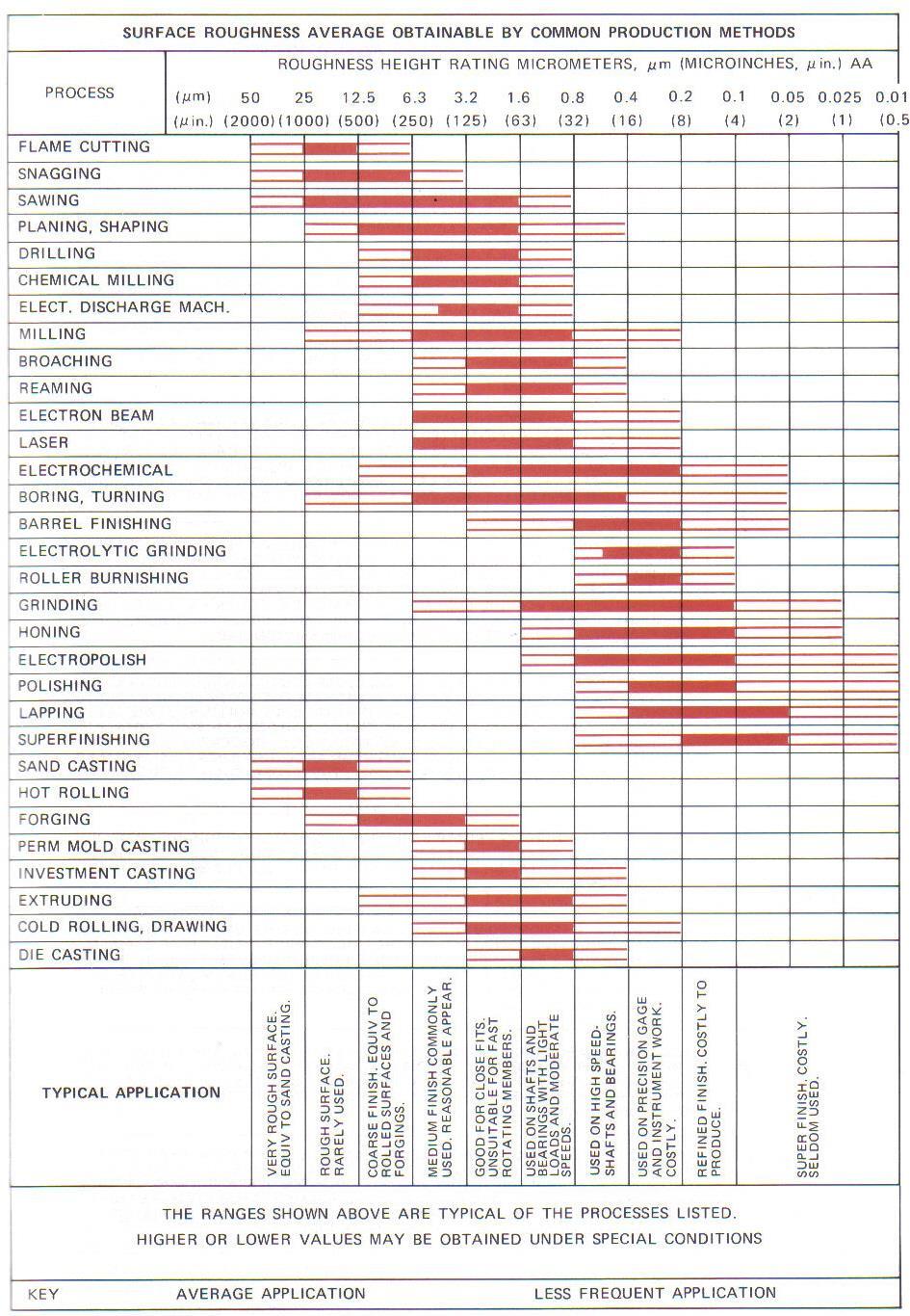
200 200
201 Welding Objectives: As a Design Drafter you should be able to: Identify welding processes. Draw welding representations and provide proper welding symbols and notes. Draw weldments from engineering sketches and actual industrial layouts. Welding: Method of fastening adjacent parts Strong Distributes and reduces weight Can decreases the size of castings or forgings Can save time and manufacturing cost Welding Drawings: Weldment - An assembly of parts welded together Welding assembly Welding subassembly American Welding Society (AWS) AWS A2.4, Standard Symbols for Welding, Brazing, and Nondestructive Examination publication Elements of Welding Drawings Assembled parts in multiview Fabrication dimensions Types of joints Welding symbols 201

202 Welding Symbols Welding Symbol Placement Basic reference for welding location and process. Arrowhead points to the weld location in the view that best shows the weld location as object lines. Can point to a hidden feature if necessary. 202
Engineering Working Drawings Basics
 Engineering Working Drawings Basics Engineering graphics is an effective way of communicating technical ideas and it is an essential tool in engineering design where most of the design process is graphically
Assembly Drawings. Definition; Description
 Assembly Drawings Definition; Description Assembly drawings show how individual parts fit together to make a machine. An assembly drawing is a drawing of an entire machine or system with all of its components
Student Name: Teacher: Date: District: Rowan. Assessment: 9_12 T and I IC61 - Drafting I Test 1. Description: Unit C - Sketching - Test 2.
 Student Name: Teacher: Date: District: Rowan Assessment: 9_12 T and I IC61 - Drafting I Test 1 Description: Unit C - Sketching - Test 2 Form: 501 1. The most often used combination of views includes the:
Copyrighted Material. Copyrighted Material. Copyrighted. Copyrighted. Material
 Engineering Graphics ORTHOGRAPHIC PROJECTION People who work with drawings develop the ability to look at lines on paper or on a computer screen and "see" the shapes of the objects the lines represent.
CE 100 Civil Engineering Drawing Sessional (Lab Manual)
") CE 100 Civil Engineering Drawing Sessional (Lab Manual) Department of Civil Engineering Ahsanullah University of Science and Technology November, 2017 1 Preface This course is designed to provide civil
CE 100 Civil Engineering Drawing Sessional (Lab Manual) Department of Civil Engineering Ahsanullah University of Science and Technology November, 2017 1 Preface This course is designed to provide civil
UNIT 5a STANDARD ORTHOGRAPHIC VIEW DRAWINGS
 UNIT 5a STANDARD ORTHOGRAPHIC VIEW DRAWINGS 5.1 Introduction Orthographic views are 2D images of a 3D object obtained by viewing it from different orthogonal directions. Six principal views are possible
11/12/2015 CHAPTER 7. Axonometric Drawings (cont.) Axonometric Drawings (cont.) Isometric Projections (cont.) 1) Axonometric Drawings
 Axonometric Drawings (cont.) Isometric Projections (cont.) 1) Axonometric Drawings") CHAPTER 7 1) Axonometric Drawings 1) Introduction Isometric & Oblique Projection Axonometric projection is a parallel projection technique used to create a pictorial drawing of an object by rotating the
CHAPTER 7 1) Axonometric Drawings 1) Introduction Isometric & Oblique Projection Axonometric projection is a parallel projection technique used to create a pictorial drawing of an object by rotating the
CHAPTER 01 PRESENTATION OF TECHNICAL DRAWING. Prepared by: Sio Sreymean
 CHAPTER 01 PRESENTATION OF TECHNICAL DRAWING Prepared by: Sio Sreymean 2015-2016 Why do we need to study this subject? Effectiveness of Graphics Language 1. Try to write a description of this object. 2.
ENGINEERING DRAWING. 1. Set squares are used to draw different angles. What is the angel a formed by the 45⁰ set square? Give a brief answer.
 ENGINEERING DRAWING 1. Set squares are used to draw different angles. What is the angel a formed by the 45⁰ set square? Give a brief answer. 2. Which is the correct method of hatching a plane surface?
Multi-View Drawing Review
 Multi-View Drawing Review Sacramento City College EDT 300/ENGR 306 EDT 300 / ENGR 306 - Chapter 5 1 Objectives Identify and select the various views of an object. Determine the number of views needed to
2004 Academic Challenge
 2004 Academic Challenge ENGINEERING GRAPHICS TEST - REGIONAL Engineering Graphics Test Production Team Ryan Brown, Illinois State University Author/Team Coordinator Kevin Devine, Illinois State University
Dimensioning. Dimensions: Are required on detail drawings. Provide the shape, size and location description: ASME Dimensioning Standards
 Dimensioning Dimensions: Are required on detail drawings. Provide the shape, size and location description: - Size dimensions - Location dimensions - Notes Local notes (specific notes) General notes ASME
2004 Academic Challenge
 2004 Academic Challenge ENGINEERING GRAPHICS TEST - SECTIONAL Engineering Graphics Test Production Team Ryan Brown, Illinois State University Author/Team Coordinator Kevin Devine, Illinois State University
A Concise Introduction to Engineering Graphics
 A Concise Introduction to Engineering Graphics Fourth Edition Including Worksheet Series A Timothy J. Sexton, Professor Department of Industrial Technology Ohio University BONUS Book on CD: TECHNICAL GRAPHICS
2003 Academic Challenge
 Worldwide Youth in Science and Engineering 2003 Academic Challenge ENGINEERING GRAPHICS TEST - REGIONAL Engineering Graphics Test Production Team Ryan Brown, Illinois State University Author/Team Coordinator
Principles and Practice:
 Principles and Practice: An Integrated Approach to Engineering Graphics and AutoCAD 2014 Randy H. Shih Multimedia Disc SDC PUBLICATIONS Better Textbooks. Lower Prices. www.sdcpublications.com Video presentations
2003 Academic Challenge
 Worldwide Youth in Science and Engineering 2003 Academic Challenge ENGINEERING GRAPHICS TEST - SECTIONAL Engineering Graphics Test Production Team Ryan Brown, Illinois State University Author/Team Coordinator
ENGINEERING GRAPHICS ESSENTIALS. (A Text and Lecture Aid) Second Edition. Kirstie Plantenberg University of Detroit Mercy SDC PUBLICATIONS
 Second Edition. Kirstie Plantenberg University of Detroit Mercy SDC PUBLICATIONS") ENGINEERING GRAPHICS ESSENTIALS (A Text and Lecture Aid) Second Edition Kirstie Plantenberg University of Detroit Mercy SDC PUBLICATIONS Schroff Development Corporation www.schroff.com www.schroff-europe.com
ENGINEERING GRAPHICS ESSENTIALS (A Text and Lecture Aid) Second Edition Kirstie Plantenberg University of Detroit Mercy SDC PUBLICATIONS Schroff Development Corporation www.schroff.com www.schroff-europe.com
2009 Academic Challenge
 2009 Academic Challenge ENGINEERING GRAPHICS TEST SECTIONAL This Test Consists of 50 Questions Engineering Graphics Test Production Team Ryan Brown, Illinois State University Author/Team Leader Kevin Devine,
Principles and Practice
 Principles and Practice An Integrated Approach to Engineering Graphics and AutoCAD 2016 Randy H. Shih SDC PUBLICATIONS Better Textbooks. Lower Prices. www.sdcpublications.com Powered by TCPDF (www.tcpdf.org)
2010 Academic Challenge
 2010 Academic Challenge ENGINEERING GRAPHICS TEST STATE FINALS This Test Consists of 40 Questions Engineering Graphics Test Production Team Ryan K. Brown, Illinois State University Author/Team Leader Jacob
ENGINEERING GRAPHICS ESSENTIALS
 ENGINEERING GRAPHICS ESSENTIALS with AutoCAD 2012 Instruction Introduction to AutoCAD Engineering Graphics Principles Hand Sketching Text and Independent Learning CD Independent Learning CD: A Comprehensive
Multiviews and Auxiliary Views
 Multiviews and Auxiliary Views Multiviews and Auxiliary Views Objectives Explain orthographic and multiview projection. Identifying the six principal views. Apply standard line practices to multiviews
Chapter 1 Overview of an Engineering Drawing
 Chapter 1 Overview of an Engineering Drawing TOPICS Graphics language Engineering drawing Projection methods Orthographic projection Drawing standards TOPICS Traditional Drawing Tools Lettering Freehand
1 st Subject: 2D Geometric Shape Construction and Division
 Joint Beginning and Intermediate Engineering Graphics 2 nd Week 1st Meeting Lecture Notes Instructor: Edward N. Locke Topic: Geometric Construction 1 st Subject: 2D Geometric Shape Construction and Division
ORTHOGRAPHIC PROJECTIONS. Ms. Sicola
 ORTHOGRAPHIC PROJECTIONS Ms. Sicola Objectives List the six principal views of projection Sketch the top, front and right-side views of an object with normal, inclined, and oblique surfaces Objectives
Geometric dimensioning & tolerancing (Part 1) KCEC 1101
 KCEC 1101") Geometric dimensioning & tolerancing (Part 1) KCEC 1101 Introduction Before an object can be built, complete information about both the size and shape of the object must be available. The exact shape of
Geometric dimensioning & tolerancing (Part 1) KCEC 1101 Introduction Before an object can be built, complete information about both the size and shape of the object must be available. The exact shape of
2016 Academic Challenge
 2016 Academic Challenge ENGINEERING GRAPHICS TEST REGIONAL This Test Consists of 40 Questions Engineering Graphics Test Production Team Ryan K. Brown, Illinois State University Author/Team Leader Mark
SOLIDWORKS 2015 and Engineering Graphics
 SOLIDWORKS 2015 and Engineering Graphics An Integrated Approach Randy H. Shih SDC PUBLICATIONS Better Textbooks. Lower Prices. www.sdcpublications.com Powered by TCPDF (www.tcpdf.org) Visit the following
MODELING AND DESIGN C H A P T E R F O U R
 MODELING AND DESIGN C H A P T E R F O U R OBJECTIVES 1. Identify and specify basic geometric elements and primitive shapes. 2. Select a 2D profile that best describes the shape of an object. 3. Identify
Contents. Notes on the use of this publication
 Contents Preface xxiii Scope Notes on the use of this publication xxv xxvi 1 Layout of drawings 1 1.1 General 1 1.2 Drawing sheets 1 1.3 Title block 2 1.4 Borders and frames 2 1.5 Drawing formats 2 1.6
Chapter 2: Dimensioning Basic Topics Advanced Topics Exercises
 Chapter 2: Dimensioning Basic Topics Advanced Topics Exercises Dimensioning: Basic Topics Summary 2-1) Detailed Drawings 2-2) Learning to Dimension 2-3) Dimension Appearance and Techniques. 2-4) Dimensioning
Chapter 8. Technical Drawings
 Chapter 8 Technical Drawing Technical Drawings Multiview drawings Also called three-view drawings Simple objects take three views Front, top, one side Title block Identifies who did the design Gives date,
Chapter 5 Pictorial sketching
 Chapter 5 Pictorial sketching Contents Freehand sketching techniques Pictorial projections - Axonometric - Oblique Isometric projection vs isometric sketch Isometric sketch from an orthographic views Isometric
Geometric Dimensioning and Tolerancing
 Geometric Dimensioning and Tolerancing (Known as GDT) What is GDT Helps ensure interchangeability of parts. Use is dictated by function and relationship of the part feature. It does not take the place
Mechanical Drawing. Unit 2 Study Guide for Chapters 6-10
 Mechanical Drawing Unit 2 Study Guide for Chapters 6-10 Chapter 6 Multiview Drawing Section 6.1 Understanding Orthographic Projection A. Technical Drawing: How can a technical drawing give more accurate
Engineering & Computer Graphics Workbook Using SOLIDWORKS
 Engineering & Computer Graphics Workbook Using SOLIDWORKS 2017 Ronald E. Barr Thomas J. Krueger Davor Juricic SDC PUBLICATIONS Better Textbooks. Lower Prices. www.sdcpublications.com Powered by TCPDF (www.tcpdf.org)
and Engineering Graphics
 SOLIDWORKS 2018 and Engineering Graphics An Integrated Approach Randy H. Shih SDC PUBLICATIONS Better Textbooks. Lower Prices. www.sdcpublications.com Powered by TCPDF (www.tcpdf.org) Visit the following
Engineering Graphics Essentials with AutoCAD 2015 Instruction
 Kirstie Plantenberg Engineering Graphics Essentials with AutoCAD 2015 Instruction Text and Video Instruction Multimedia Disc SDC P U B L I C AT I O N S Better Textbooks. Lower Prices. www.sdcpublications.com
DWG 002. Blueprint Reading. Geometric Terminology Orthographic Projection. Instructor Guide
 DWG 002 Blueprint Reading Geometric Terminology Orthographic Projection Instructor Guide Introduction Module Purpose The purpose of the Blueprint Reading modules is to introduce students to production
Engineering Graphics, Class 8 Orthographic Projection. Mohammad I. Kilani. Mechanical Engineering Department University of Jordan
 Engineering Graphics, Class 8 Orthographic Projection Mohammad I. Kilani Mechanical Engineering Department University of Jordan Multi view drawings Multi view drawings provide accurate shape descriptions
DFTG-1305 Technical Drafting Prof. Francis Ha
 DFTG-1305 Technical Drafting Prof. Francis Ha Session 5 Dimensioning Geisecke s textbook: 14 th Ed. Chapter 10 p. 362 15 th Ed. Chapter 11 p. 502 Update: 17-0508 Dimensioning Part 1 of 2 Dimensioning Summary
Engineering & Computer Graphics Workbook Using SolidWorks 2014
 Engineering & Computer Graphics Workbook Using SolidWorks 2014 Ronald E. Barr Thomas J. Krueger Davor Juricic SDC PUBLICATIONS Better Textbooks. Lower Prices. www.sdcpublications.com Powered by TCPDF (www.tcpdf.org)
(Ans:d) a. A0 b. A1 c. A2 d. A3. (Ans:b) (Ans:a) (Ans:d) (Ans:d)
 a. A0 b. A1 c. A2 d. A3. (Ans:b) (Ans:a) (Ans:d) (Ans:d)") Multiple Choice Questions (MCQ) on Engineering Drawing (Instruments) The mini drafter serves the purpose of everything except a. Scales b. Set square c. Protractor d. Compass (Ans:d) During operation,
Multiple Choice Questions (MCQ) on Engineering Drawing (Instruments) The mini drafter serves the purpose of everything except a. Scales b. Set square c. Protractor d. Compass (Ans:d) During operation,
Isometric Drawing Chapter 26
 Isometric Drawing Chapter 26 Sacramento City College EDT 310 EDT 310 - Chapter 26 - Isometric Drawing 1 Drawing Types Pictorial Drawing types: Perspective Orthographic Isometric Oblique Pictorial - like
Philadelphia University Faculty of Engineering Mechanical Engineering Department
 Philadelphia University Faculty of Engineering Mechanical Engineering Department Basics of Engineering Drawing Manual Done by:- Eng. Laith R.I. Batarseh Eng. Hanan Khamis 2017 1 Table of contents SUBJECT
Beginning Engineering Graphics 3 rd Week Lecture Notes Instructor: Edward N. Locke Topic: The Coordinate System, Types of Drawings and Orthographic
 Beginning Engineering Graphics 3 rd Week Lecture Notes Instructor: Edward N. Locke Topic: The Coordinate System, Types of Drawings and Orthographic 1 st Subject: The Cartesian Coordinate System The Cartesian
ISOMETRIC PROJECTION. Contents. Isometric Scale. Construction of Isometric Scale. Methods to draw isometric projections/isometric views
 ISOMETRIC PROJECTION Contents Introduction Principle of Isometric Projection Isometric Scale Construction of Isometric Scale Isometric View (Isometric Drawings) Methods to draw isometric projections/isometric
ENGINEERING GRAPHICS ESSENTIALS
 ENGINEERING GRAPHICS ESSENTIALS Text and Digital Learning KIRSTIE PLANTENBERG FIFTH EDITION SDC P U B L I C AT I O N S Better Textbooks. Lower Prices. www.sdcpublications.com ACCESS CODE UNIQUE CODE INSIDE
ME1105 Engineering Drawing & Design
 City University London Term 1 Assessment 2008/2009 School of Engineering and Mathematical Sciences ME1105 Engineering Drawing & Design Student Name:.., Group: Examination duration: Reading time: This paper
ENGINEERING GRAPHICS ESSENTIALS
 ENGINEERING GRAPHICS ESSENTIALS with AutoCAD 2012 Instruction Introduction to AutoCAD Engineering Graphics Principles Hand Sketching Text and Independent Learning CD Independent Learning CD: A Comprehensive
2007 Academic Challenge
 2007 Academic Challenge ENGINEERING GRAPHICS TEST - STATE FINALS This Test Consists of 50 Questions Engineering Graphics Test Production Team Ryan Brown, Illinois State University Author/Team Coordinator
AutoCAD Tutor 2011 Support Docs
 AutoCAD Tutor 2011 Support Docs CHAPTER 1 CUSTOMIZING THE QUICK ACCESS TOOLBAR One of the advantages of the Quick Access Toolbar is the ability to display the AutoCAD commands that you frequently use.
1. is the modification of an existing product or process. A. Invention C. Recreation B. Innovation D. Enhancement
 Introduction to Engineering Design Lewis-Palmer School District #38, Monument, Colorado Fall Semester 2008 Final Exam 1. is the modification of an existing product or process. A. Invention C. Recreation
2013 Academic Challenge
 2013 Academic Challenge ENGINEERING GRAPHICS TEST STATE FINALS This Test Consists of 40 Questions Engineering Graphics Test Production Team Ryan Brown, Illinois State University Author/Team Leader Jacob
1 st Subject: Types and Conventions of Dimensions and Notes
 Beginning Engineering Graphics 7 th Week Lecture Notes Instructor: Edward N. Locke Topic: Dimensions, Tolerances, Graphs and Charts 1 st Subject: Types and Conventions of Dimensions and Notes A. Definitions
Study Unit. Auxiliary Views. This sneak preview of your study material has been prepared in advance of the book's actual online release.
 Study Unit Auxiliary Views This sneak preview of your study material has been prepared in advance of the book's actual online release. iii Preview You re entering now into another subject area in your
DFTG 1305 UNIT 1. Semester: Spring 2016 Class #: Term: SS Instructor: Mays ALSabbagh
 DFTG 1305 UNIT 1 Semester: Spring 2016 Class #: 94412 Term: SS Instructor: Mays ALSabbagh Technical Drafting Unit One: Introduction to Drafting Chapter 1 : The World Wide Graphic language for Design Lecture
Multiview Projection
 DFTG-1305 Technical Drafting Prof. Francis Ha Session 4 Multiview Projection (or Orthographic Projection) Reading: Geisecke s textbook: 14 th Ed. Chapter 5 p.162 15 th Ed. Chapter 6 p.232 Update: 17-0510
Multiview Drawing. Definition: Graphical representation of a 3- dimensional object on one plane (sheet of paper) using two or more views.
 using two or more views.") Multiview Drawing Definition: Graphical representation of a 3- dimensional object on one plane (sheet of paper) using two or more views. Multiview Drawing Another name for multiview drawing is orthographic
Multiview Drawing Definition: Graphical representation of a 3- dimensional object on one plane (sheet of paper) using two or more views. Multiview Drawing Another name for multiview drawing is orthographic
GUIDELINES FOR DRAFTING
 UNIT 1 GUIDELINES FOR DRAFTING 1.1 Introduction The term draughting is used to describe the language of drafting in this book. It defines the terminology, symbology, conventions, and standards used in
C A R I B B E A N E X A M I N A T I O N S C O U N C I L REPORT ON CANDIDATES WORK IN THE SECONDARY EDUCATION CERTIFICATE EXAMINATION MAY/JUNE 2010
 C A R I B B E A N E X A M I N A T I O N S C O U N C I L REPORT ON CANDIDATES WORK IN THE SECONDARY EDUCATION CERTIFICATE EXAMINATION MAY/JUNE 2010 TECHNICAL DRAWING GENERAL PROFICIENCY Copyright 2010 Caribbean
Sketching Fundamentals
 Sketching Fundamentals Learning Outcome When you complete this module you will be able to: Make basic engineering sketches of plant equipment. Learning Objectives Here is what you will be able to do when
Guide To British Standards
 Guide To British Standards Higher Graphic Communication C O N T E N T S page TITLE BLOCK 2 DRAWING SCALES 2 LINE TYPES 3 ORTHOGRAPHIC PROJECTION 4 SECTIONAL VIEWS 4 SCREW THREADS & COMPONENTS 7 INTERUPTTED
2009 Academic Challenge
 2009 Academic Challenge ENGINEERING GRAPHICS TEST STATE FINALS This Test Consists of 50 Questions Engineering Graphics Test Production Team Ryan Brown, Illinois State University Author/Team Leader Kevin
2. To develop basic skills in the use of drawing instruments and drafting techniques.
 IT-111 ENGINEERING DRAFTING SYLLABUS Instructor: R. Edward Rode= Office: Room 110-4, Anzalone Hall Hours: Refer to Schedule Phone: (985-549-2092) Fax : (985-549-5532) Email : erode@selu.edu Course Title:
GOVERNMENT POLYTECHNIC, VALSAD MECHANICAL ENGINEERING DEPARTMENT ASSIGNMENT SUB: MECHANICAL DRAFTING (C321901) TERM:172
 TERM:172") GOVERNMENT POLYTECHNIC, VALSAD MECHANICAL ENGINEERING DEPARTMENT ASSIGNMENT SUB: MECHANICAL DRAFTING (C321901) TERM:172 1) When all the dimension are placed above the dimension line, it is called (a) Aligned
GOVERNMENT POLYTECHNIC, VALSAD MECHANICAL ENGINEERING DEPARTMENT ASSIGNMENT SUB: MECHANICAL DRAFTING (C321901) TERM:172 1) When all the dimension are placed above the dimension line, it is called (a) Aligned
ORTHOGRAPHIC PROJECTION
 ORTHOGRAPHIC PROJECTION C H A P T E R S I X OBJECTIVES 1. Recognize and the symbol for third-angle projection. 2. List the six principal views of projection. 3. Understand which views show depth in a drawing
Chapter 6. Architectural Lines and Lettering
 Chapter 6 Architectural Lines and Lettering Drafting Introduction Universal graphic language Uses lines, symbols, dimensions, and notes to describe a structure to be built Properly drawn lines are dark,
Downloaded from ENGINEERING DRAWING. Time allowed : 3 hours Maximum Marks : 70
 ENGINEERING DRAWING Time allowed : 3 hours Maximum Marks : 70 Note : (i) (ii) Attempt all the questions. Use both sides of the drawing sheet, if necessary. (iii) All dimensions are in millimeters. (iv)
Chapter 5 SECTIONS OF SOLIDS 5.1 INTRODUCTION
 Chapter 5 SECTIONS OF SOLIDS 5.1 INTRODUCTION We have studied about the orthographic projections in which a 3 dimensional object is detailed in 2-dimension. These objects are simple. In engineering most
SDC PUBLICATIONS. Schroff Development Corporation
 SDC PUBLICATIONS Schroff Development Corporation www.schroff.com www.schroff-europe.com SECTIONING In chapter 3 you will learn how to create various types of sectional views. Sectional views allow you
2. Line composed of closely and evenly spaced short dashes in a drawing represents
 1. Hidden lines are drawn as (a) dashed narrow lines (b) dashed wide lines (c) long-dashed dotted wide line (d) long-dashed double dotted wide line Ans: (a) 2. Line composed of closely and evenly spaced
Unit 4: Geometric Construction (Chapter4: Geometry For Modeling and Design)
") Unit 4: Geometric Construction (Chapter4: Geometry For Modeling and Design) DFTG-1305 Technical Drafting Instructor: Jimmy Nhan OBJECTIVES 1. Identify and specify basic geometric elements and primitive
Unit 4: Geometric Construction (Chapter4: Geometry For Modeling and Design) DFTG-1305 Technical Drafting Instructor: Jimmy Nhan OBJECTIVES 1. Identify and specify basic geometric elements and primitive
CAD Mechanical Design I
 EXAM INFORMATION Items 58 Points 85 Prerequisites NONE Course Length ONE SEMESTER Career Cluster ARCHITECTURE AND CONSTRUCTION MANUFACTURING SCIENCE, TECHNOLOGY, ENGINEERING AND MATHEMATICS Performance
Bridge Course On Engineering Drawing for Mechanical Engineers
 G. PULLAIAH COLLEGE OF ENGINEERING AND TECHNOLOGY Accredited by NAAC with A Grade of UGC, Approved by AICTE, New Delhi Permanently Affiliated to JNTUA, Ananthapuramu (Recognized by UGC under 2(f) and 12(B)
TECHNICAL DESIGN I (540)
") DESCRIPTION The first assessment in a series, Technical Design I prepares students to develop technical knowledge and skills required to plan and prepare scale pictorial interpretations of engineering
DESCRIPTION The first assessment in a series, Technical Design I prepares students to develop technical knowledge and skills required to plan and prepare scale pictorial interpretations of engineering
Contents. Foreword. Using this Guide
 Foreword xv Preface xvii Scope Using this Guide xix xix 1 Specifying technical products 1 1.1 What is meant by technical product specification? 1 1.2 Design brief 1 1.3 Function 1 1.4 Specifications 2
Trade of Metal Fabrication. Module 3: Plate Fabrication Unit 12: Duct Sections Phase 2
 Trade of Metal Fabrication Module 3: Plate Fabrication Unit 12: Duct Sections Phase 2 Table of Contents List of Figures... 4 List of Tables... 5 Document Release History... 6 Module 3 Plate Fabrication...
Geometry For Technical Drawing Chapter 4
 Geometry For Technical Drawing Chapter 4 Sacramento City College EDT 300/ENGR 306 EDT 300/ENGR 306 1 Objectives Identify and describe geometric shapes and constructions used by drafters. Construct various
Chapter 5 Pictorial Projection
 Chapter 5 Pictorial Projection Objectives After completing this chapter, the students will be able to Create freehand sketches using the correct sketching techniques. Explainthe difference between axonometric
DELHI TECHNOLOGICAL UNIVERSITY ENGINEERING GRAPHICS LAB MANUAL
 DELHI TECHNOLOGICAL UNIVERSITY ENGINEERING GRAPHICS LAB MANUAL NAME: - ROLL NO: - GROUP: - BRANCH: - GROUP TEACHER: Page 1 www.rooplalrana.com 1 GENERAL INSTRUCTIONS FOR ENGG. GRAPHICS LAB 1) Students
DFTG-1305 Technical Drafting Prof. Francis Ha
 DFTG-1305 Technical Drafting Prof. Francis Ha Session 4 Orthographic Projection (or Multiview Projection) Reading: Geisecke s textbook: 14 th Ed. Chapter 5 p.162 15 th Ed. Chapter 6 p.232 Update: 18-0205
Engineering Graphics UNIVERSITY OF TEXAS RIO GRANDE VALLEY JAZMIN LEY HISTORY OF ENGINEERING GRAPHICS GEOMETRIC CONSTRUCTION & SOLID MODELING
 Engineering Graphics UNIVERSITY OF TEXAS RIO GRANDE VALLEY JAZMIN LEY HISTORY OF ENGINEERING GRAPHICS GEOMETRIC CONSTRUCTION & SOLID MODELING Overview History of Engineering Graphics: Sketching, Tools,
Drawing sheet: - The various size of the drawing sheet used for engineering drawing as per IS Are listed in the table
 Dronacharya Group of Institutions, Greater Noida Computer Aided Engineering Graphics (CAEG) (NCE 151/251) List of Drawing Sheets: 1. Letter writing & Dimensioning. 2. Projection of Points & Lines. 3. Projection
Student Name: Teacher: Date: District: Rowan. Assessment: 9_12 T and I IC61 - Drafting I Test 2. Description: Drafting 1 - Test 6.
 Student Name: Teacher: Date: District: Rowan Assessment: 9_12 T and I IC61 - Drafting I Test 2 Description: Drafting 1 - Test 6 Form: 501 1. 2X on a hole note means: A. Double the size of the hole. B.
60 Most Important Engineering Drawing Questions
 1. If a client of yours is having difficulty visualizing a design, what type of drawing would be the easiest to understand? A. axonometric B. three-view orthographic C. one-view orthographic D. bimetric
Student Name: Teacher: Date: District: Rowan. Assessment: 9_12 T and I IC61 - Drafting I Test 1. Form: 501
 Student Name: Teacher: Date: District: Rowan Assessment: 9_12 T and I IC61 - Drafting I Test 1 Description: Test 4 A (Diagrams) Form: 501 Please use the following figure for this question. 1. In the GEOMETRIC
ENGINEERING GRAPHICS
 ENGINEERING GRAPHICS Time allowed : 3 hours Maximum Marks : 70 Note : (ii) Attempt all the questions. Use both sides of the drawing sheet, if necessary. (iii) All dimensions are in millimetres. (iv) Missing
Project Booklet. Structural Drafting with AutoCAD
 Project Booklet Structural Drafting with AutoCAD Introduction 1 General Setup 2 Border and Title Block 3 Drafting the Foundation Plan (Plate 1) 8 Drafting the South Elevation (Plate 2) 11 Drafting Section
COURSE SYLLABUS. Course Prefix Number:
 COURSE SYLLABUS COURSE IDENTIFICATION Course Prefix Number: ETEC121 Course Title: Engineering Graphics I Division: Applied Science Division Program: Industrial Engineering Technology Credit Hours: 3 Revision
Orthographic and Pictorial Views
 ASME Y14.3-2012 [Revision of ASME Y14.3-2003 (R2008) and Consolidation of ASME Y14.4M-1989 (R2009)] Orthographic and Pictorial Views Engineering Drawing and Related Documentation Practices AN AMERICAN
2012 Academic Challenge
 2012 Academic Challenge ENGINEERING GRAPHICS TEST SECTIONAL This Test Consists of 40 Questions Engineering Graphics Test Production Team Ryan Brown, Illinois State University Author/Team Leader Jacob Borgerson,
3. The dimensioning SYMBOLS for arcs and circles should be given:
 Draft Student Name: Teacher: District: Date: Wake County Test: 9_12 T and I IC61 - Drafting I Test 2 Description: 4.08 Dimensioning Form: 501 1. The MINIMUM amount of space between two, ADJACENT DIMENSION
Orthographic and Pictorial Views
 ASME Y14.3-2012 [Revision of ASME Y14.3-2003 (R2008) and Consolidation of ASME Y14.4M-1989 (R2009)] Orthographic and Pictorial Views Engineering Drawing and Related Documentation Practices AN AMERICAN
Activity 5.2 Making Sketches in CAD
 Activity 5.2 Making Sketches in CAD Introduction It would be great if computer systems were advanced enough to take a mental image of an object, such as the thought of a sports car, and instantly generate
UNIT Lines and Symbols
 3 UNIT Lines and Symbols Various lines on a drawing have different meanings. They may appear solid, broken, thick, or thin. Each is designed to help the blueprint reader make an interpretation. The standards
1 st Subject: Types of Pictorial Drawings (Isometric, Oblique, and Perspective)
") Intermediate Engineering Graphics 4 th Week 1 st Meeting Lecture Notes Instructor: Edward N. Locke Topic: Types of pictorial drawings (isometric, oblique, and perspective), isometric sketching and drafting
Intermediate Engineering Graphics 4 th Week 1 st Meeting Lecture Notes Instructor: Edward N. Locke Topic: Types of pictorial drawings (isometric, oblique, and perspective), isometric sketching and drafting
Introduction to Autodesk Inventor User Interface Student Manual MODEL WINDOW
 Emmett Wemp EDTECH 503 Introduction to Autodesk Inventor User Interface Fill in the blanks of the different tools available in the user interface of Autodesk Inventor as your instructor discusses them.
1. Open the Feature Modeling demo part file on the EEIC website. Ask student about which constraints needed to Fully Define.
 BLUE boxed notes are intended as aids to the lecturer RED boxed notes are comments that the lecturer could make Control + Click HERE to view enlarged IMAGE and Construction Strategy he following set of