Assembly Drawings. Definition; Description
|
|
|
- Reynard Watson
- 5 years ago
- Views:
Transcription
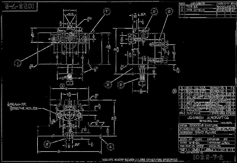
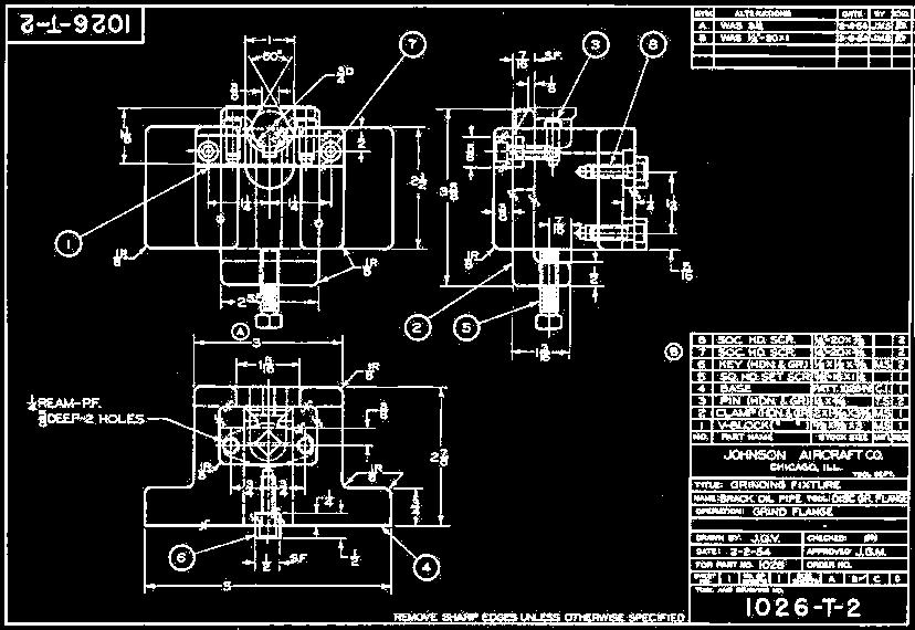
1 Assembly Drawings Definition; Description Assembly drawings show how individual parts fit together to make a machine. An assembly drawing is a drawing of an entire machine or system with all of its components located and identified. Required for most products Generally multiview (orthographic projection) with as few views as possible Sections are common Few or no hidden lines Few or no dimensions Different Types; Assembly Drawings General Assembly; all parts are drawn in their working position Detail Assembly; all parts are drawn in their working position with dimensions Sub Assembly Pictorial Assembly Exploded Assembly; the parts are separately displayed, but they are aligned according to their assembly positions and sequences Elements of an Assembly Drawing One or more views Auxiliary, section, and enlarged views as needed Arrangement of parts Overall size and assembly dimensions Manufacturing processes associated with assembly Identification numbers Parts list 1
2 Example Drawing; General Assembly Detail Assembly Working-drawing assembly Less common Uses fewer sheets Sometimes used in a manufacturer s catalog or web site Subassembly Combined with part components to form the general assembly Includes item numbers and parts list Requires own detail drawings Examples; a car engine, bike derailleur, compressor in an AC Pictorial Assembly Assist workers in product assembly Product catalogs or brochures Sales promotion Customer self-assembly Maintenance procedures Identification Numbers Item numbers (ALWAYS numbered BOTTOM UP). Key the parts from the assembly drawing to the parts list Generally placed in balloons; balloon size.500 diameter hardcopy Some companies use identification letters Leader arrowheads or dots 2

3 Parts List Also known as Bill of Materials (BOM) Also known as List of Materials Usually combined with the assembly drawing Location above or to the left of the title block Upper right or left corner of the sheet alternate location Convenient location on the drawing field Can appear on a separate sheet Must include clear and complete purchase part information. If it is NOT a standard part then the actual company name must be included in with the description. Elements of a Parts List (see also Drawing Order below) Item number (find number); ALWAYS BOTTOM UP Quantity required Part or identifying number (company assigned) Nomenclature or description Material identification Vendor information; name of company if NOT a standard part Sheet number Placing ALL Information 3
4 Leader lines point to the corresponding part. Balloons containing part numbers. Balloons are placed in orderly horizontal or vertical rows (aligned order) Leader lines; - should not cross, - be as parallel as possible. 4
5 Parts list may be placed in the lower right corner of the drawing. - Part# 1 is at the bottom. Standard Parts Standard parts include any part that can be bought off the shelf. They do not need to be drawn. Purchasing information is given on the standard parts sheet attached to the back of the working drawing package. Drawing Order Drawings included in a working drawing package should be presented in the following order. Assembly drawing (first sheet) Part Number 1 Part Number 2... Standard parts sheet (last sheet) 5
6 Parts List Text Justification Use Middle, Center for Part #, and Qty. Use Middle Left for Part Numbers and Descriptions. General Practices The number of views can be one, two, three or more as needed, but it should be kept to a minimum. Good viewing direction is that what represents all (or most) of the parts assembled in their working position. Hidden lines usually omitted unless they are absolutely necessary to illustrate some important feature that the worker might otherwise miss. Leader lines to balloons do not cross. Leader lines are drawn in the oblique direction, every 15 degrees angles but NOT drawn at 0, 90, 190, or 270 degrees. Balloons are created at diameter.500 (hardcopy). Balloons are drawn aligned as much as possible horizontally and vertically. Section lines is usually needed to clarify mating parts. Use different section lines styles for adjacent parts. Do NOT draw section lines on sectional view of standard parts such as threaded fasteners, washers, solid shafts, pins, and keys. Example Drawings Exploded Technical Illustration Illustrated parts breakdown 6

7 General Assembly: 7

8 Detailed Assembly 8
Chapter 12 Assembly Drawings Topics Exercises
 Chapter 12 Assembly Drawings Topics Exercises Assembly : Topics Summary 12.1) Definitions 12.2) Views Used in Assembly Drawings 12.3) Things to Include/Not Include 12.4) Standard Parts - Specifications
Engineering Working Drawings Basics
 Engineering Working Drawings Basics Engineering graphics is an effective way of communicating technical ideas and it is an essential tool in engineering design where most of the design process is graphically
ME 114 Computer Aided Engineering Drawing - II
 ME 114 Computer Aided Engineering Drawing - II Assembly Drawing Exercises Asst.Prof.Dr.Turgut AKYÜREK Çankaya University, Ankara Working Drawing/Production Drawing The drawings that are used to give information
ME1105 Engineering Drawing & Design
 City University London Term 1 Assessment 2008/2009 School of Engineering and Mathematical Sciences ME1105 Engineering Drawing & Design Student Name:.., Group: Examination duration: Reading time: This paper
Introducing Design Revision into a Freshman Level Engineering Graphics Course
 Introducing Design Revision into a Freshman Level Engineering Graphics Course N. E. Study Department of Mechanical Engineering Technology Penn State Erie - The Behrend College E. R. Evans Jr. Department
COMPUTER AIDED DESIGN DRAFTING ENGINEERING DESIGN STANDARDS MANUAL
 COMPUTER AIDED DESIGN DRAFTING ENGINEERING DESIGN STANDARDS MANUAL Created by: T. Frech; CADD Instructor Created: March, 2014 Last Revised: May 19, 2015 1 Table of Contents Drafting & Drafting Management
8 Working Drawings in AutoCAD
 8 Working Drawings in AutoCAD Most engineering designs consist of more than a single part. Usually there are a several or many parts that must fit and work together. When we are creating the drawings of
MULTIPLE CHOICE QUESTIONS - CHAPTER 6
 MULTIPLE CHOICE QUESTIONS - CHAPTER 6 1. The selection of the front view in executing a multiview drawing of an object is dependent upon the following factors: a. size and shape of the object and their
Student Name: Teacher: Date: District: Rowan. Assessment: 9_12 T and I IC61 - Drafting I Test 2. Description: Drafting 1 - Test 6.
 Student Name: Teacher: Date: District: Rowan Assessment: 9_12 T and I IC61 - Drafting I Test 2 Description: Drafting 1 - Test 6 Form: 501 1. 2X on a hole note means: A. Double the size of the hole. B.
Dimensioning. Dimensions: Are required on detail drawings. Provide the shape, size and location description: ASME Dimensioning Standards
 Dimensioning Dimensions: Are required on detail drawings. Provide the shape, size and location description: - Size dimensions - Location dimensions - Notes Local notes (specific notes) General notes ASME
3. The dimensioning SYMBOLS for arcs and circles should be given:
 Draft Student Name: Teacher: District: Date: Wake County Test: 9_12 T and I IC61 - Drafting I Test 2 Description: 4.08 Dimensioning Form: 501 1. The MINIMUM amount of space between two, ADJACENT DIMENSION
Term Design Project Details
 Term Design Project Details ME170 Project Description: Form teams* of 3 to 4 students and design a new mechanical or electro-mechanical product. The product should have moving parts. Your product will
Dimensioning in the figure below could be improved by: A
 1-Multiview-study Page 1 of 8 irections For Numbers 1-53 : Read each of the following multiple-choice items and the possible answers carefully. Mark the letter of the correct answer on your answer sheet
Principles and Practice:
 Principles and Practice: An Integrated Approach to Engineering Graphics and AutoCAD 2014 Randy H. Shih Multimedia Disc SDC PUBLICATIONS Better Textbooks. Lower Prices. www.sdcpublications.com Video presentations
C A R I B B E A N E X A M I N A T I O N S C O U N C I L REPORT ON CANDIDATES WORK IN THE SECONDARY EDUCATION CERTIFICATE EXAMINATION MAY/JUNE 2010
 C A R I B B E A N E X A M I N A T I O N S C O U N C I L REPORT ON CANDIDATES WORK IN THE SECONDARY EDUCATION CERTIFICATE EXAMINATION MAY/JUNE 2010 TECHNICAL DRAWING GENERAL PROFICIENCY Copyright 2010 Caribbean
2. To develop basic skills in the use of drawing instruments and drafting techniques.
 IT-111 ENGINEERING DRAFTING SYLLABUS Instructor: R. Edward Rode= Office: Room 110-4, Anzalone Hall Hours: Refer to Schedule Phone: (985-549-2092) Fax : (985-549-5532) Email : erode@selu.edu Course Title:
ORTHOGRAPHIC PROJECTIONS. Ms. Sicola
 ORTHOGRAPHIC PROJECTIONS Ms. Sicola Objectives List the six principal views of projection Sketch the top, front and right-side views of an object with normal, inclined, and oblique surfaces Objectives
Principles and Practice
 Principles and Practice An Integrated Approach to Engineering Graphics and AutoCAD 2016 Randy H. Shih SDC PUBLICATIONS Better Textbooks. Lower Prices. www.sdcpublications.com Powered by TCPDF (www.tcpdf.org)
Chapter 2: Dimensioning Basic Topics Advanced Topics Exercises
 Chapter 2: Dimensioning Basic Topics Advanced Topics Exercises Dimensioning: Basic Topics Summary 2-1) Detailed Drawings 2-2) Learning to Dimension 2-3) Dimension Appearance and Techniques. 2-4) Dimensioning
Multiview Projection
 DFTG-1305 Technical Drafting Prof. Francis Ha Session 4 Multiview Projection (or Orthographic Projection) Reading: Geisecke s textbook: 14 th Ed. Chapter 5 p.162 15 th Ed. Chapter 6 p.232 Update: 17-0510
11/12/2015 CHAPTER 7. Axonometric Drawings (cont.) Axonometric Drawings (cont.) Isometric Projections (cont.) 1) Axonometric Drawings
 Axonometric Drawings (cont.) Isometric Projections (cont.) 1) Axonometric Drawings") CHAPTER 7 1) Axonometric Drawings 1) Introduction Isometric & Oblique Projection Axonometric projection is a parallel projection technique used to create a pictorial drawing of an object by rotating the
CHAPTER 7 1) Axonometric Drawings 1) Introduction Isometric & Oblique Projection Axonometric projection is a parallel projection technique used to create a pictorial drawing of an object by rotating the
Technological Design Mr. Wadowski. Orthographic & Isometric Drawing Lesson
 Technological Design Mr. Wadowski Orthographic & Isometric Drawing Lesson TOPICS Working Drawings, Isometric Drawings & Orthographic Drawings Glass box concept Multiview projection Orthographic projection
SDC PUBLICATIONS. Schroff Development Corporation
 SDC PUBLICATIONS Schroff Development Corporation www.schroff.com www.schroff-europe.com SECTIONING In chapter 3 you will learn how to create various types of sectional views. Sectional views allow you
Standards for Working Drawings
 Standards for Working Drawings 11 September 2006 Department of Mechanical Engineering, Mechatronic Engineering, and Manufacturing Technology California State University, Chico Chico, California 95929-078
Mechanical Drawing. Unit 2 Study Guide for Chapters 6-10
 Mechanical Drawing Unit 2 Study Guide for Chapters 6-10 Chapter 6 Multiview Drawing Section 6.1 Understanding Orthographic Projection A. Technical Drawing: How can a technical drawing give more accurate
JUNIOR AGRICULTURAL MECHANICS SHOW
 JUNIOR AGRICULTURAL MECHANICS SHOW Documentation & Research Package Format shown is an example you may follow in developing your Documentation Package. It was developed to help clarify the process. You
Multiviews and Auxiliary Views
 Multiviews and Auxiliary Views Multiviews and Auxiliary Views Objectives Explain orthographic and multiview projection. Identifying the six principal views. Apply standard line practices to multiviews
Exploded View Extracting Drawings. ENGR 1182 SolidWorks 08
 Exploded View Extracting Drawings ENGR 1182 SolidWorks 08 Today s Objectives Formal Drawing Components: Exploded View Extracted Drawings SW07 In-Class Activity SW07 Out-of-Class Homework Assignment Formal
DFTG-1305 Technical Drafting Prof. Francis Ha
 DFTG-1305 Technical Drafting Prof. Francis Ha Session 4 Orthographic Projection (or Multiview Projection) Reading: Geisecke s textbook: 14 th Ed. Chapter 5 p.162 15 th Ed. Chapter 6 p.232 Update: 18-0205
CAD and Drafting Standards Working Drawings
 CAD and Drafting Standards Working Drawings Gregory Mocko Introduction 2 The purpose of drawing or generating a CAD document is to communicate Essentially, since communication is the goal, some standards
UNIT 5a STANDARD ORTHOGRAPHIC VIEW DRAWINGS
 UNIT 5a STANDARD ORTHOGRAPHIC VIEW DRAWINGS 5.1 Introduction Orthographic views are 2D images of a 3D object obtained by viewing it from different orthogonal directions. Six principal views are possible
ENGINEERING DRAWING SKKK 1021 ISOMETRIC DRAWING. Agus Arsad, Azizul Azri Bin Mustaffa 10/2/2012 1
 ENGINEERING DRAWING SKKK 1021 ISOMETRIC DRAWING Agus Arsad, Azizul Azri Bin Mustaffa 10/2/2012 1 LEARNING OUTCOMES ISOMETRIC DRAWING It is expected that students will be able to: Understand the significance
Lesson 22 Coupling Assembly (Video Lesson)
") Lesson 22 Coupling Assembly (Video Lesson) Figure 22.1 Coupling Assembly OBJECTIVES Model the Shaft, Taper Coupling, and Straight Coupling components Use Assembly commands Apply Analysis to determine Global
Lesson 22 Coupling Assembly (Video Lesson) Figure 22.1 Coupling Assembly OBJECTIVES Model the Shaft, Taper Coupling, and Straight Coupling components Use Assembly commands Apply Analysis to determine Global
CHAPTER 01 PRESENTATION OF TECHNICAL DRAWING. Prepared by: Sio Sreymean
 CHAPTER 01 PRESENTATION OF TECHNICAL DRAWING Prepared by: Sio Sreymean 2015-2016 Why do we need to study this subject? Effectiveness of Graphics Language 1. Try to write a description of this object. 2.
Aircraft Drawing and Blueprint Reading
 Aircraft Drawing and Blueprint Reading Course Introduction Types of drawings Engineering also known as production or working drawings. Block diagram Types of Drawings Schematics Sketches Charts and graphs
Guide To British Standards
 Guide To British Standards Higher Graphic Communication C O N T E N T S page TITLE BLOCK 2 DRAWING SCALES 2 LINE TYPES 3 ORTHOGRAPHIC PROJECTION 4 SECTIONAL VIEWS 4 SCREW THREADS & COMPONENTS 7 INTERUPTTED
Introduction to Engineering Design. Part A
 Introduction to Engineering Design Final Examination Part A Spring 2005 Student Name: Date: Class Period: Total Points: Directions: Select the letter of the response which best completes the item or answers
GOVERNMENT POLYTECHNIC, VALSAD MECHANICAL ENGINEERING DEPARTMENT ASSIGNMENT SUB: MECHANICAL DRAFTING (C321901) TERM:172
 TERM:172") GOVERNMENT POLYTECHNIC, VALSAD MECHANICAL ENGINEERING DEPARTMENT ASSIGNMENT SUB: MECHANICAL DRAFTING (C321901) TERM:172 1) When all the dimension are placed above the dimension line, it is called (a) Aligned
GOVERNMENT POLYTECHNIC, VALSAD MECHANICAL ENGINEERING DEPARTMENT ASSIGNMENT SUB: MECHANICAL DRAFTING (C321901) TERM:172 1) When all the dimension are placed above the dimension line, it is called (a) Aligned
Exploded View Extracting Drawings. ENGR 1182 SolidWorks 08
 Exploded View Extracting Drawings ENGR 1182 SolidWorks 08 Today s Objectives Formal Drawing Components: Exploded View Extracted Drawings SW07 Activity SW07 Application Formal Drawings Definition: First
At the conclusion of this unit you should be able to accomplish the following with a 70% accuracy
 7 Multiview Drawing OBJECTIVES At the conclusion of this unit you should be able to accomplish the following with a 70% accuracy 1. explain the importance of mulitview drawing as a communication tool far
Multiview Drawing. Definition: Graphical representation of a 3- dimensional object on one plane (sheet of paper) using two or more views.
 using two or more views.") Multiview Drawing Definition: Graphical representation of a 3- dimensional object on one plane (sheet of paper) using two or more views. Multiview Drawing Another name for multiview drawing is orthographic
Multiview Drawing Definition: Graphical representation of a 3- dimensional object on one plane (sheet of paper) using two or more views. Multiview Drawing Another name for multiview drawing is orthographic
Drawing Standards & Conventions for IDD
 Drawing Standards & Conventions for IDD This document consists of a set of standards that have been developed to maintain a consistency in Interior Decoration and Design students work. The standards are
Production drawing Diagram. a) I am a freehand drawing that follows technical drawing standards.
 I am a freehand drawing that follows technical drawing standards.") THE TECHNOLOGICAL WORLD Graphical language STUDENT BOOK Ch. 11, pp. 336 342 Basic lines, geometric lines, sketches 1. In technology, the two most widely used types of technical drawings are: a) sketch
THE TECHNOLOGICAL WORLD Graphical language STUDENT BOOK Ch. 11, pp. 336 342 Basic lines, geometric lines, sketches 1. In technology, the two most widely used types of technical drawings are: a) sketch
SOLIDWORKS 2015 and Engineering Graphics
 SOLIDWORKS 2015 and Engineering Graphics An Integrated Approach Randy H. Shih SDC PUBLICATIONS Better Textbooks. Lower Prices. www.sdcpublications.com Powered by TCPDF (www.tcpdf.org) Visit the following
1 st Subject: Types and Conventions of Dimensions and Notes
 Beginning Engineering Graphics 7 th Week Lecture Notes Instructor: Edward N. Locke Topic: Dimensions, Tolerances, Graphs and Charts 1 st Subject: Types and Conventions of Dimensions and Notes A. Definitions
ME 111: Engineering Drawing
 ME 111: Engineering Drawing Lecture 5 12-08-2011 Orthographic projection and Projection of Points Indian Institute of Technology Guwahati Guwahati 781039 1 Orthographic Projection A parallel projection
v1.0 ASSEMBLY GUIDE Mia Wide Bookcase
 v1.0 ASSEMBLY GUIDE Mia Wide Bookcase Components Upon unpacking your bookcase from it s delivery box, you should have the pieces shown. Follow the steps on the next pages to assemble your new bookcase.
ENGINEERING GRAPHICS ESSENTIALS
 ENGINEERING GRAPHICS ESSENTIALS with AutoCAD 2012 Instruction Introduction to AutoCAD Engineering Graphics Principles Hand Sketching Text and Independent Learning CD Independent Learning CD: A Comprehensive
DIMENSIONING ENGINEERING DRAWINGS
 DIMENSIONING ENGINEERING DRAWINGS An engineering drawing must be properly dimensioned in order to convey the designer s intent to the end user. Dimensions provide the information needed to specify the
DFTG-1305 Technical Drafting Prof. Francis Ha
 DFTG-1305 Technical Drafting Prof. Francis Ha Session 5 Dimensioning Geisecke s textbook: 14 th Ed. Chapter 10 p. 362 15 th Ed. Chapter 11 p. 502 Update: 17-0508 Dimensioning Part 1 of 2 Dimensioning Summary
Honors Drawing/Design for Production (DDP)
") Honors Drawing/Design for Production (DDP) Unit 1: Design Process Time Days: 49 days Lesson 1.1: Introduction to a Design Process (11 days): 1. There are many design processes that guide professionals
Honors Drawing/Design for Production (DDP) Unit 1: Design Process Time Days: 49 days Lesson 1.1: Introduction to a Design Process (11 days): 1. There are many design processes that guide professionals
and Engineering Graphics
 SOLIDWORKS 2018 and Engineering Graphics An Integrated Approach Randy H. Shih SDC PUBLICATIONS Better Textbooks. Lower Prices. www.sdcpublications.com Powered by TCPDF (www.tcpdf.org) Visit the following
Drawing and Detailing with SolidWorks 2014
 r n fo io n at io c at tifi ar er ep c pr WT es D R u d Pcl In C S W e th W E N Drawing and Detailing with SolidWorks 2014 Referencing the ASME Y14 Engineering Drawing and Related Documentation Practices
Isometric Drawing Chapter 26
 Isometric Drawing Chapter 26 Sacramento City College EDT 310 EDT 310 - Chapter 26 - Isometric Drawing 1 Drawing Types Pictorial Drawing types: Perspective Orthographic Isometric Oblique Pictorial - like
2. Line composed of closely and evenly spaced short dashes in a drawing represents
 1. Hidden lines are drawn as (a) dashed narrow lines (b) dashed wide lines (c) long-dashed dotted wide line (d) long-dashed double dotted wide line Ans: (a) 2. Line composed of closely and evenly spaced
5. Creating Sectional Views
 5. Creating Sectional Views Quite often an outside view of an object does not adequately describe it, as no internal features are shown. In order to show the internal features without excessive use of
Interpretation of Drawings. An Introduction to the Basic Concepts of Creating Technical Drawings
 Interpretation of Drawings An Introduction to the Basic Concepts of Creating Technical Drawings Introduction In the design process drawings are the main way in which information about an object or product
CE 100 Civil Engineering Drawing Sessional (Lab Manual)
") CE 100 Civil Engineering Drawing Sessional (Lab Manual) Department of Civil Engineering Ahsanullah University of Science and Technology November, 2017 1 Preface This course is designed to provide civil
CE 100 Civil Engineering Drawing Sessional (Lab Manual) Department of Civil Engineering Ahsanullah University of Science and Technology November, 2017 1 Preface This course is designed to provide civil
ENGINEERING DRAWING LECTURE 4
 ENGINEERING DRAWING LECTURE 4 Conventions Convention or Code: The representation of any matter by some sign or mark on the drawing is known as convention or code. The convention make the drawing simple
Course Title: Mechanical Drawing Topic/Concept: Views Of Objects Time Allotment: 3 6 Weeks Unit Sequence: 1 Major Concepts to be learned:
 Course Title: Mechanical Drawing Topic/Concept: Views Of Objects Time Allotment: 3 6 Weeks Unit Sequence: 1 1. Sketching skills 2. Orthographic projection 3. Visualization of views 4. Location of lines
2012 Academic Challenge
 2012 Academic Challenge ENGINEERING GRAPHICS TEST SECTIONAL This Test Consists of 40 Questions Engineering Graphics Test Production Team Ryan Brown, Illinois State University Author/Team Leader Jacob Borgerson,
PLTW IED MID TERM EXAM REVIEW Part A Multiple Choice
 2014-15 PLTW IED MID TERM EXAM REVIEW Part A Multiple Choice Directions: Select the letter of the response which best completes the item or answers the question. Then record your answer on the answer sheet
Upcoming Events This Week : LPQ
 Upcoming Events This Week : LPQ Extracting Drawings - DEMO Although most demos are implemented with word documents, this demo employs slides so that more details can be shown to the students as the drawing
Chapter 8. Technical Drawings
 Chapter 8 Technical Drawing Technical Drawings Multiview drawings Also called three-view drawings Simple objects take three views Front, top, one side Title block Identifies who did the design Gives date,
Certified SOLIDWORKS Professional Advanced Preparation Materials
 Includes Preparation for Five Advanced Certification Exams Certified SOLIDWORKS Professional Advanced Preparation Materials Sheet Metal, Weldments, Surfacing, Mold Tools and Drawing Tools SOLIDWORKS 2016
- 9_12TI7962-QUIZ2 - Print Test
 Page 1 of 5 Report: Test Answer Key District: Madison Test: Description: Unit B CAD Form: 501 1. What CAD dimensioning command allows a line to be drawn from a note to an object? (NCCTE.9_12.TI.7962.D202.01)
ENGINEERING GRAPHICS ESSENTIALS. (A Text and Lecture Aid) Second Edition. Kirstie Plantenberg University of Detroit Mercy SDC PUBLICATIONS
 Second Edition. Kirstie Plantenberg University of Detroit Mercy SDC PUBLICATIONS") ENGINEERING GRAPHICS ESSENTIALS (A Text and Lecture Aid) Second Edition Kirstie Plantenberg University of Detroit Mercy SDC PUBLICATIONS Schroff Development Corporation www.schroff.com www.schroff-europe.com
ENGINEERING GRAPHICS ESSENTIALS (A Text and Lecture Aid) Second Edition Kirstie Plantenberg University of Detroit Mercy SDC PUBLICATIONS Schroff Development Corporation www.schroff.com www.schroff-europe.com
AutoCAD Tutor 2011 Support Docs
 AutoCAD Tutor 2011 Support Docs CHAPTER 1 CUSTOMIZING THE QUICK ACCESS TOOLBAR One of the advantages of the Quick Access Toolbar is the ability to display the AutoCAD commands that you frequently use.
ORTHOGRAPHIC PROJECTION
 ORTHOGRAPHIC PROJECTION INTRODUCTION Any object has three dimensions, that is, length, width and thickness. A projection is defined as a representation of an object on a two dimensional plane. The projections
ENGINEERING DRAWING. 1. Set squares are used to draw different angles. What is the angel a formed by the 45⁰ set square? Give a brief answer.
 ENGINEERING DRAWING 1. Set squares are used to draw different angles. What is the angel a formed by the 45⁰ set square? Give a brief answer. 2. Which is the correct method of hatching a plane surface?
1 ISOMETRIC PROJECTION SECTION I: INTRODUCTION TO ISOMETRIC PROJECTION
 1 ISOMETRIC PROJECTION SECTION I: INTRODUCTION TO ISOMETRIC PROJECTION Orthographic projection shows drawings of an object in a two-dimensional format, with views given in plan, elevation and end elevation
Test Answers and Exam Booklet. Geometric Tolerancing
 Test Answers and Exam Booklet Geometric Tolerancing iii Contents ANSWERS TO THE GEOMETRIC TOLERANCING TEST............. 1 Part 1. Questions Part 2. Calculations SAMPLE ANSWERS TO THE GEOMETRIC TOLERANCING
the same information given in two different 1. Dimensions should NOT be duplicated, or Dimension Guidelines Incorrect ways.
 Dimension Guidelines 1. Dimensions should NOT be duplicated, or the same information given in two different ways. Incorrect 1. Dimensions should NOT be duplicated, or the same information given in two
AUXILIARY VIEWS C H A P T E R N I N E
 AUXILIARY VIEWS C H A P T E R N I N E Giesecke, Hill, Spencer, Dygdon, Novak, Lockhart, Goodman 1 OBJECTIVES 1. Create an auxiliary view from orthographic views. 2. Draw folding lines or reference-plane
Geometric dimensioning & tolerancing (Part 1) KCEC 1101
 KCEC 1101") Geometric dimensioning & tolerancing (Part 1) KCEC 1101 Introduction Before an object can be built, complete information about both the size and shape of the object must be available. The exact shape of
Geometric dimensioning & tolerancing (Part 1) KCEC 1101 Introduction Before an object can be built, complete information about both the size and shape of the object must be available. The exact shape of
Copyrighted Material. Copyrighted Material. Copyrighted. Copyrighted. Material
 Engineering Graphics ORTHOGRAPHIC PROJECTION People who work with drawings develop the ability to look at lines on paper or on a computer screen and "see" the shapes of the objects the lines represent.
CDT: DESIGN AND COMMUNICATION
 CDT: DESIGN AND COMMUNICATION Paper 7048/01 Structured Key message Whilst many excellent answers were seen, the following were considered to be areas where improvement could be made: the correct positioning
ENGR 1182 Exam 1 First Mid Term Exam Study Guide and Practice Problems
 Spring Semester 2016 ENGR 1182 Exam 1 First Mid Term Exam Study Guide and Practice Problems Disclaimer Problems in this study guide resemble problems relating mainly to the pertinent homework assignments.
CAD Mechanical Design I
 EXAM INFORMATION Items 58 Points 85 Prerequisites NONE Course Length ONE SEMESTER Career Cluster ARCHITECTURE AND CONSTRUCTION MANUFACTURING SCIENCE, TECHNOLOGY, ENGINEERING AND MATHEMATICS Performance
DUE DATE: Friday 4/6/2018 at 3:30 PM
 MECH 130 SPRING 2018 CAD LAB 4 FINAL REVISION HARDCOPIES NEEDED DUE DATE: Friday 4/6/2018 at 3:30 PM After the revised hitch, the ball and the pin parts were created from the Handout call LAB4 PART Creation,
A Concise Introduction to Engineering Graphics
 A Concise Introduction to Engineering Graphics Fourth Edition Including Worksheet Series A Timothy J. Sexton, Professor Department of Industrial Technology Ohio University BONUS Book on CD: TECHNICAL GRAPHICS
SOLIDWORKS 2018 Basic Tools
 SOLIDWORKS 2018 Basic Tools Getting Started with Parts, Assemblies and Drawings Paul Tran CSWE, CSWI SDC PUBLICATIONS Better Textbooks. Lower Prices. www.sdcpublications.com Powered by TCPDF (www.tcpdf.org)
2004 Academic Challenge
 2004 Academic Challenge ENGINEERING GRAPHICS TEST - SECTIONAL Engineering Graphics Test Production Team Ryan Brown, Illinois State University Author/Team Coordinator Kevin Devine, Illinois State University
Glass Box Projection. Gives you 6 sides to view of an object. 10/2/14 2
 2D Drawings Glass Box Projection Gives you 6 sides to view of an object. 10/2/14 2 We can simplify this for some objects to 3 views Glass Box Approach Glass Box Approach Glass Box Approach Glass Box Approach
Extracting Drawings - DEMO
 Extracting Drawings - DEMO Although most demos are implemented with word documents, this demo employs slides so that more details can be shown to the students as the drawing is constructed. College of
GL5: Visualisation and reading drawings
 436-105 Engineering Communications GL5:1 GL5: Visualisation and reading drawings Being able to both: represent a 3D object in multiview drawings interpret a multiview drawing to visualise a 3D object is
Design Representation 1
 Once a design is conceptualized, it must be represented and communicated to others in a complete and technically accurate fashion. GET130 Intro to Engineering Technology Fall 2016 Communication methods:
Isometric Drawings. Figure A 1
 A Isometric Drawings ISOMETRIC BASICS Isometric drawings are a means of drawing an object in picture form for better clarifying the object s appearance. These types of drawings resemble a picture of an
Ch 2. Scale Drawings and Proportions
 Ch 2. Scale Drawings and Proportions Examples: Some can be done by inspection Ratios can be changed to look like fractions, and then solved using cross multiplication. 1 2.1 Work with Scales. A Scale is
2009 Academic Challenge
 2009 Academic Challenge ENGINEERING GRAPHICS TEST SECTIONAL This Test Consists of 50 Questions Engineering Graphics Test Production Team Ryan Brown, Illinois State University Author/Team Leader Kevin Devine,
Orthographic Drawing (Architectural Board Drafting)
") Design and Drafting Description In this activity, the teacher will introduce orthographic projection, in which a multi-view drawing shows how the sides of an object are related to each another. Students
Design and Drafting Description In this activity, the teacher will introduce orthographic projection, in which a multi-view drawing shows how the sides of an object are related to each another. Students
Anchor Block Draft Tutorial
 Anchor Block Draft Tutorial In the following tutorial you will create a drawing of the anchor block shown. The tutorial covers such topics as creating: Orthographic views Section views Auxiliary views
2016 Academic Challenge
 2016 Academic Challenge ENGINEERING GRAPHICS TEST REGIONAL This Test Consists of 40 Questions Engineering Graphics Test Production Team Ryan K. Brown, Illinois State University Author/Team Leader Mark
2004 Academic Challenge
 2004 Academic Challenge ENGINEERING GRAPHICS TEST - REGIONAL Engineering Graphics Test Production Team Ryan Brown, Illinois State University Author/Team Coordinator Kevin Devine, Illinois State University
2009 Academic Challenge
 2009 Academic Challenge ENGINEERING GRAPHICS TEST STATE FINALS This Test Consists of 50 Questions Engineering Graphics Test Production Team Ryan Brown, Illinois State University Author/Team Leader Kevin
LANVRT10. Instructions. Lankota Vertical Unload Auger Removal Tool for JD 00 to S series combines. 270 West Park Avenue Huron, SD
 LANVRT10 Instructions Lankota Vertical Unload Auger Removal Tool for JD 00 to S series combines 270 West Park Avenue Huron, SD 57350 866-526-5682 Page 1 Numerical Parts List Part Numbers Description Quantity
Quick Start for Autodesk Inventor
 Quick Start for Autodesk Inventor Autodesk Inventor Professional is a 3D mechanical design tool with powerful solid modeling capabilities and an intuitive interface. In this lesson, you use a typical workflow
Leaving Certificate 201
 Coimisiún na Scrúduithe Stáit State Examinations Commission Leaving Certificate 201 Marking Scheme Design and Communication Graphics Ordinary Level Note to teachers and students on the use of published
Chapter 7. Fasteners
 Chapter 7 Fasteners LEARNING OBJECTIVES After studying this chapter, students will be able to: Identify several types of fasteners. Explain why inch-based fasteners are not interchangeable with metric-based
Lecture #11. Assembly modeling and assembling parts RES 112E COMPUTER AIDED TECHNICAL DRAWING ITU
 Lecture #11 Assembly modeling and assembling parts This week You will learn how to assemble the parts. The steps to follow are: oassembly drawing oassembly section obill of materials oexploded assembly