B.E. I & II SEM ENGINEERING GRAPHICS
|
|
|
- May Fletcher
- 5 years ago
- Views:
Transcription
1 B.E. I & II SEM ENGINEERING GRAPHICS
2 UNIT -I
3 Drawing: The way of conveying the ideas through the systematic lines on the paper. The art of representation of an object by systematic lines on a paper. Classification: 1. Artistic Drawing (Free-hand or Model Drawing): The art of representation of an object by the artist by his imagination or by keeping the object before him. e.g. paintings, cinema posters, advertisement boards, etc. 2. Engineering Drawing (Instrument Drawing): The art of representation of engineering objects. e.g. buildings, roads, machines, etc.
4 Types of Engineering Drawing: i. Geometrical Drawing: e.g. geometrical objects - rectangle, square, cube, cone, cylinder, etc. a. Plain Geometrical Drawing: Two dimensional drawing having only length and breadth. e.g. square, triangle, etc. b. Solid Geometrical Drawing: Three dimensional drawing having length, breadth and thickness. e.g. cube, prism, etc. ii. Mechanical Engineering or Machine Drawing: e.g. mechanical engineering objects machines, machine parts, etc. iii. Civil Engineering Drawing: e.g. civil engineering objects roads, buildings, bridges, dams, etc. iv. Electrical & Electronics Engineering Drawing: e.g. electrical and electronics objects transformers, wiring diagrams.
5 Drawing Instruments and Other Drawing Materials: 1. Drawing Board 2. Drawing Sheet 3. Drawing Sheet Holder 4. Set-squares 45 o and 30 o 60 o 5. Large size Compass 6. Small bow Compass 7. Large size Divider 8. Small bow Divider 9. Scales 6 and Protractor 11. French Curve 12. Drawing Pencils H, 2H, HB 13. Sand Paper 14. Eraser (Rubber) 15. Drawing Pins and Clips 16. Cello Tape 17. Duster or Handkerchief 18. Drafting Machine / Mini Drafter 19. Sketch Book (Medium size) 20. Roller Scale 21. Pencil Sharpener 22. Sheet Folder
6 Layout of Drawing Sheet 150 Title Block All the dimensions are millimeters.
7 Title Block (Sample) NAME: AMAR ROLL NO.: ME/08/3753 RCET, BHILAI SEM. & SEC.: I (H) LINES SUB. DATE: 09/01/09 & SHEET NO.: 01 GRADE: A++++ LETTERING CHECKED BY: NOTES: All the dimensions are in millimeters. Name and Roll No. should be written by ink-pen.
8 LINES Line Thickness: Thickness varied according to the use of pen or pencil and the size & type of the drawing. For pencil, the lines can be divided into two line-groups: Line-group (mm) Thicknes s Lines 0.2 Medium Out lines, dotted lines, cutting plane lines 0.1 Thin Centre lines, section lines, dimension lines, extension lines, construction lines, leader lines, short-break lines and long-break lines. Important Notes: In the finished drawing, all lines except construction lines should be dense, clean and uniform. Construction lines should be drawn very thin and faint and should be hardly visible.
9 Types of Lines Lines Description General Applications A Continuous thick A1 B C D Continuous thin (straight / curve) Continuous thin (free-hand) Continuous thin (straight with zigzags) A2 B1 B2 B3 B4 B5 B6 B7 C1 C2 D1 Visible outlines Visible edges Imaginary lines of intersection Dimension lines Projection lines Leader lines Hatching or section lines Outlines of revolved sections in plane Short centre lines Limits of partial or interrupted views and sections Short-break lines Long-break lines
10 Lines Description General Applications E Dashed thick E1 E2 F Dashed thin F1 F2 G Chain thin G1 H Chain thin, thick at ends and changes of direction G2 G3 H1 Hidden outlines Hidden edges Hidden outlines Hidden edges Centre lines Lines of symmetry Trajectories Cutting planes J Chain thick J1 Indication of lines or surfaces to which a special treatment applies K Chain thin doubledashed K1 K2 K3 K4 Outlines of adjacent parts Alternative and extreme positions of movable parts Centroidal lines Parts situated in front of the cutting plane
11 G1 H1 G3 P P E1 80 o A1 B5 90 B2 B4 Ø10 K2 J1 D1 C1 Application of various types of lines according to B.I.S.
12 Lettering Writing of titles, dimensions, notes and other important particulars on a drawing Classification: 1. Single-stroke Letters: The thickness of the line of the letter is obtained in one stroke of the pencil. Recommended by B.I.S. It has two types: i. Vertical ii. Inclined (slope 75 o with the horizontal) The ratio of height to width varies but in most of the cases it is 6:5. Lettering is generally done in capital letters. The lower-case letters are generally used in architectural drawings.
13 The spacing between two letters should not be necessarily equal. The letters should be so placed that they do not appear too close together too much apart. The distance between the words must be uniform and at least equal to the height of the letters. Lettering, except the dimension figures, should be underlined to make them more prominent. Size of Alphabets for Drawing: Main titles mm Sub titles mm Notes, dimension figures, etc mm Drawing no mm 2. Gothic Letters: Stems of single-stroke letters are given more thickness (vary from 1/5 to 1/10 of the height of the letters). Mostly used for main titles of ink-drawings.
14 d/2 d ABCDEFGHIJKLMN OPQRSTUVWXYZ abcdefghijklmnopqrs tuvwxyz
15 L S Dimensioning The art of writing the various sizes or measurement on the finished drawing of an object. Types of Dimensioning: i. Size or Functional Dimensions (S): It indicates sizes. e.g. length, breadth, height, diameter, etc. ii. Location or Datum Dimensions (L): It shows location or exact position of various constructional details within the object. L L S
16 X Notations of Dimensioning Symbol Note 2 Holes, Ø12 Leader (at 30 o,45 o,60 o ) 90 Extension line Dimension line Dimension figure Arrow-head 3X Arrow-head
17 1. Dimension line: Thin continuous line used to indicate the measurement. 2. Extension line: Thin continuous line extending beyond the outline of the object. 3. Arrow-head: Used to terminate the dimension line. Length : width ratio is 3:1. Space filled up. 4. Note: Gives information regarding specific operation relating to a feature. 5. Leader: Thin continuous line connecting a note or a dimension figure with the feature to which it is applied. Terminated by arrow-head or dot. 6. Symbol: The representation of any object by some mark on the drawing. It saves time and labour.
18 30 60 System of Placing Dimensions Ø16 Ø Aligned System Unidirectional System
19 System of Placing Dimensions 1. Aligned System: All the dimensions are so placed that they may read from the bottom or the right hand edges of the drawing sheet. All the dimensions are placed normal and above the dimension line. Commonly used in Engineering Drawing. 2. Unidirectional System: All the dimensions are so placed that they may read from the bottom edge of the drawing sheet. Dimension lines are broken near the middle for inserting the dimensions. Commonly used on large drawing aircrafts, automobiles.
20 Units of Dimensioning As for as possible all dimensions should be given in millimeters omitting the abbreviation mm. If another unit is used, only the dimension figures should be written. But a foot note such as All the dimensions are in centimeters is inserted in a prominent place near the title box. e.g (Zero must precede the decimal point.) ±.75 ( Zero is omitted.)
21 The ways of Placing the Dimensions in a Series Chain Parallel
22 The ways of Placing the Dimensions in a Series Combined Progressive
23 The ways of Placing the Dimensions in a Series 1. Chain Dimensioning: Dimensions are arranged in a straight line. 2. Parallel Dimensioning: All the dimensions are shown from a common base line. The smaller dimension is placed nearer the view. 3. Combined Dimensioning: Chain and parallel dimensioning used simultaneously. 4. Progressive Dimensioning: One datum or surface is selected which reads as zero. All the dimensions are referred to that point or surface.
24 Some Important Rules for Dimensioning 1. All the dimensions necessary for the correct functioning of the part should be expressed directly on the drawing. 2. Every dimension should be given, but none should be given more than once. 3. A dimension should be placed on the view where its use is shown more clearly. 4. Dimensions should be placed outside the view, as for as possible. 5. Mutual crossing of dimension lines and dimensioning between hidden lines should be avoided. Also it should not cross any other line of the drawing. 6. An outline or a centre line should never be used as a dimension line. A centre line may be extended to serve as an extension line. 7. Aligned system of dimensioning is recommended. 8. Dimension lines should be drawn at least 8 mm away from the outlines and from each other. 9. MYcsvtu The extension Notes line should be extended by about 3 mm beyond the dimension line.
25 10. When the space is too narrow, the arrow-head may be placed outside. Also a dot may be used to replace an arrow-head The various methods of dimensioning different sizes of circles are as follows: Ø10 Ø20 Ø Arcs of circles should be dimensioned by their respective radii. R8 R3 R6
26 13. Radii of a spherical surface and square cross section of a rod is shown as below: Sphere R20 SQ Angular dimension may be given as follows: o 45 Length of Chord Length of Arc
27 h H 15. Method of dimensioning of Chamfer: 2 45 o 16. Dimensioning of Tapered Surface: L Slope or Taper = (H-h)/L
28 INTRODUCTION A scale is defined as the ratio of the linear dimensions of element of the object as represented in a drawing to the actual dimensions of the same element of the object itself. SIZES OF THE SCALES Drawing drawn of the same size as the objects, are called full-size drawings and the scale used is known as full-size scale.
29 It may not be always possible to prepare full size drawings.they are, therefore, drawn proportionality smaller or larger. When drawings are drawn smaller than the actual size of the object (as in case of building, bridge, large machines etc. ) the scale used is said to be a reducing scale (1:5). Drawing of small machine parts, mathematical instruments, watches etc. are made larger than their real size. These are said to be drawn on an enlarging scale (5:1).
. Length of the drawing R.F. = Actual length of object")
30 The ratio of the length of the drawing to the actual length of the object represented is called the representative fraction (i.e. R.F.). Length of the drawing R.F. = Actual length of object
31 When a 1 cm long line in a drawing represents 1 metre length of the object, the R.F. is equal to [1 cm / 1 metre] = [1 cm / 100 cm ] = 1/100 And the scale of the drawing of the drawing will be 1:100 or 1/100 full size.
32 When an unusual scale is used, it is constructed on the drawing sheet. To construct a scale the following information is essential: (1) RF of the scale (2) The unit which it must represent, for example millimeter, centimeter, feet and inches etc. (3) The maximum length which it must show.
33 The length of the scale is determined by the formula: Length of the scale = R.F. Maximum length It may not be always possible to draw as long a scale as to measure the longest length in the drawing. The scale is there fore drawn 15 cm to 30 cm long, longer length being measured by marking them off in parts
34 The scales used in practice are classified as under: (1) Plain scales (2) Diagonal scales (3) Comparative scales (4) Vernier scales (5) Scale of Chord
35 A Plain scale consist of a line divided into suitable number of equal parts or units, the first of which is subdivided into smaller parts. Plain scales represent either two units or a unit and its sub division. (1)The zero should be placed at the end of the first main division, i.e. between the unit and its sub divisions.
36 (2) From the zero mark, the units should be numbered to right and its sub divisions to the left. (3)The names of the units and the sub divisions should be stated clearly below or at the respective ends. (4) The name of the scale (i.e. scale, 10) or its RF should be mentioned below the scale.
37 Construct a scale of 1:4 to show centimeters and long enough to measure up to 5 decimeters (1)Determine the RF of the scale. Here it is 1:4 (2)Determine the length of the scale length of the scale = RF max. length =[1:4] 5 dm = 12.5 cm (3)Draw a line of 12.5 cm long and divide it into 5 equal divisions, each representing 1dm
38 (4) Mark 0 the end of the first division and 1,2,3and 4 at the end of each subsequent division to its right. (5) Divide the first division into 10 equal sub division, each representing 1 cm. (6) Mark cms to the left of 0 as shown in figure.
39 Construct a scale of R.F.1/60 to read yards and feet, and long enough to measure up to 5 yards. Length of the scale = R.F. max. length = [ 1/60] 5 yard = 3 inches Draw a line 3 inches long and divide it into 5 equal parts. Divide the first part into 3 equal divisions. Mark the scale as shown in figure.
40
41 A Diagonal scale is used when very minute distances such as 0.1 mm etc. are to be accurately measured or when measurements are required in three units. For example, dm, cm, and mm or yard, foot and inch.
42 To obtain division of a given short line AB in multiples of 1/10 its length, e.g. 0.1AB, 0.2 AB. At any end,say B, draw a line perpendicular to AB and along it, step-off ten equal division of any length, starting from B and ending at C. Number the division points 9,8, Join A with C.
43 Through the points 1,2,etc.draw lines parallel to AB and cutting AC at 1,2 etc. it is evident that triangles 1 1C,2 2C----ABC are similar. Since C5 = 0.5BC, the line 5 5 = 0.5AB. Similarly,1 1=0.1 AB,2 2=0.2AB etc. Thus each horizontal line below AB becomes progressively shorter in length by 1/10 AB giving lengths in multiple of 0.1 AB.
44
45 Construct a diagonal scale of 3:200 showing metres, decimetres and centimetres and to measure up to 6 metres.
46 Length of the scale =[2/6] Χ 6m = 9 cm. Draw a line AB 9 cm long and divide it into 6 equal parts. each part will show a metre. Divide the first part AO into 10 equal divisions, each showing decimetre or 0.1 m. At A erect a perpendicular and step off along it 10 equal divisions of any length, ending at D. complete the rectangle ABCD. Erect perpendiculars at metre divisions 0,1,2,3 and 4.
47 Draw horizontal lines through the division points on AD. Join D with the end of the first division along AO, viz. the point 9. Through the remaining points I.e.8,7,6 etc. draw lines parallel to D9. In triangle OFE, FE represents 1 dm or 0.1m. Each horizontal line below FE progressively diminishes in length by 0.1FE. Thus, the next line below FE is equal to 0.9FE and represents 0.9 A 1dm = 0.9dmor 0.09m or 9 cm. Any length between 1 CM OR 0.01M measured from this scale. and 6 m can be
48 Construct a diagonal scale of R.F.1:4000 to show metres and long enough to measure up to 500 metres. Length of the scale =[1/4000] Χ 500m = 12.5 cm. Draw a line 12.5 cm long and divide it into 5 equal parts, each part will show 100 metre. Divide the first part into ten equal divisions, each divisions will show 10 metres. At the left hand end, erect a perpendicular and on it, step off 10 equal divisions of any length. Draw the rectangle and complete the scale as explained earlier.
49
50 The area of a field is 50,000 sq. m. the length and the breadth of the field, on the map is 10cm and 8 cm respectively. Construct a diagonal scale which can read up to one metre. Mark the length of 235 metre on the scale. What is the RF of the scale?
51 Area of the field = 50,000 sq. m. Area of the field on the map = 10cm Χ 8cm = 80cm 2 1 sq. cm = / 80 = 625 sq. m. Now RF =1 cm / 25 m =1 / 2500 Length of the scale = [1/ 2500] Χ [500 Χ 100 ] = 20 cm Take 20 cm length and divide it into 5 equal parts. Complete the scale as explained earlier.
52 PROBLEMS FOR SHEET NUMBER :- 3 Q1. The distance between Vadodara and Surat is 130 km. A train covers this distance in 2.5 hours. Construct a plain scale to measure time up to a single minute. The R.F. of the scale is 1/ Find the distance covered by the train in 45 minutes. Q2. On a building plan, a line 20 cm long represents a distance of 10m. Devise a diagonal scale for the plan to read up to 12 m, showing meters, decimeters and centimeters. Show on your scale the lengths 6.48m and 11.14m.
53 PROBLEMS FOR SHEET NUMBER :- 3 Q3. A room of 1728 m 3 volume is shown by a cube of 216 cm3 volume. Find R.F. and construct a plain scale to measure up to 42 m. Mark a distance of 22 m on the scale. Q4. A car is running at a speed of 50 km/hr. Construct a diagonal scale to show 1 km by 3 cm and measure up to 6 km. Mark also on the scale the distance covered by the car in 5 minutes 28 seconds.

54 Curves used in Engineering Practice: 1. Conic sections 2. Cycloidal curves 3. Involute 4. Evolutes 5. Spirals 6. Helix
55 CONIC SECTIONS The sections obtained by the intersection of a right circular cone by a cutting plane in different position relative to the axis of the cone are called Conics or Conic sections The conic section can be defined by two ways: 1. By cutting a right circular cone with a sectional plane. 2. Mathematically, i.e., with respect to the loci of a point moving in a plane. Apex Generator Axis Base RIGHT CIRCULAR CONE
56 Definition of conic sections by cutting a right circular cone with a sectional plane. Circle When the cutting plane AA is perpendicular to the axis and cuts all the generators Ellipse When the cutting plane BB is inclined to the axis of the cone and cut all the generators on one side of the apex Parabola When the cutting plane CC is inclined to the axis of the cone and parallel to one of the generator. Hyperbola When the cutting plane DD makes a smaller angle with the axis than that of the angle made by the generators of the cone. E E A B C D D AA GIVES CIRCLE BB GIVES ELLIPSE CC GIVES PARABOLA DD GIVES HYPERBOLA EE GIVES RECTANGULAR HYPERBOLA C A B
57 CONIC SECTIONS CIRCLE ELLIPSE PARABOLA HYPERBOLA
58 Definition of conic sections mathematically, i.e., with respect to the loci of a point moving in a plane. Conic: It is defined as the locus of a point moving in a plane in such a way that the ratio of its distance from a fix point (focus) to a fixed straight line (directrix), is always constant. The ratio is called eccentricity. Ellipse Eccentricity is always less than 1 Parabola Eccentricity is always equal to 1 Hyperbola Eccentricity is always greater than 1 D E C E E D P V F F2 V 2 P P HYPERBOLA (e>1) PARABOLA (e=1) ELLIPSE (e<1) CA =AXIS V = VERTEX F = FOCUS DD = DIRECTRIX PF PE e ECCENTRICITY A
59 Mathematically a ellipse can be described by an equation (x 2 / a 2 ) + (y 2 / b 2 ) =1; (where a & b are semi-major and semiminor axis respectively) Use of elliptical curves is made in Arches Bridges Dams Man-holes etc.
60 Method of Construction of Ellipse 1. General method (Eccentricity method) 2. Arc of circle method 3. Concentric circle method 4. Oblong method NOTE: Use 1 method when e and CF is given Use any method out of rest when major and minor axis are given
61 GENERAL METHOD (ECCENTRICITY METHOD) Construct an ellipse when the distance of the focus from the directrix is equal to 50 mm and eccentricity is 2/3 Draw any vertical line AB as directrix. At any point C in it, draw the axis. Mark a focus F on the axis such that CF=50 mm. Divide CF into 5 equal divisions Mark the vertex V on the third division- point from C. (Thus e = VF/VC = 2/3) CONT
62 A scale is now constructed on the axis which will directly give the distances in the required ratio. At V draw a perpendicular VE equal to VF. Draw a line joining C and E. Thus in triangle CVE, VE / VC = VF / VC = 2/3 Mark any point 1 on the axis and through it, draw a perpendicular through 1 at points P 1 and P 1 Similarly, mark points 2, 3 etc. on the axis and obtain points P 2 and P 2, P 3 and P 3 etc. Draw a smooth curve through these points, which is ellipse. It is a closed curve having two foci and two directrices.
63 GENERAL METHOD (ECCENTRICITY METHOD) Construct an ellipse when the distance of the focus from the directrix is equal to 50 mm and eccentricity is 2/3
64 The sum of the distances of any point on the curve from the two foci is equal to the major axis. Let AB Major Axis; CD Minor Axis F 1 & F 2 Foci Points A,P,C etc. are on the ellipse curve. According to the definition, But AF 1 + AF 2 = PF 1 + PF 2 = CF 1 + CF 2 etc. AF 1 + AF 2 = AB, the major axis Therefore, PF 1 + PF 2 = AB The distance of the sum of the ends of the minor axis from the foci is equal to the major axis. CF1 + CF2 = AB But CF 1 = CF 2 Therefore, CF1 = CF2 = (1/2)AB
65 ARC OF CIRCLE METHOD Construct an ellipse, given the major and minor axes. Draw a line AB equal to the major axis and a line CD equal to the minor axis, bisecting each other at right angles at O. With the centre C and radius equal to half AB,. Draw arcs cutting AB at F1 and F2, the foci of the ellipse. Mark a number of points 1, 2, 3 etc. on AB. With centers F1 and F2, and radius equal to A1, draw arcs on both sides of AB. CONT
66 With same centres and radius equal to B1, Draw arcs intersecting the previous arcs at four points marked P1. Similarly with radii A2 and B2, A3 and B3 etc. obtain more points. Draw a smooth curve through these points. This curve is the required ellipse
67
68 CONCENTRIC CIRCLE METHOD Construct an ellipse, given the major and minor axes. Draw the major axis AB and the minor axis CD, intersecting at O. With centre O draw two circle with diameters AB and CD respectively. Divide major axis circle in equal no of parts, say 12 and mark points 1,2,3 Join each point (1,2,3 ) with centre O, these lines cut minor axis circle, mark those point 1,2,3 CONT
69 Draw a line from point 1, parallel to CD Draw a line from point 1, parallel to AB Both lines intersect at a point P1, is on the required ellipse Repeat the construction through all the points(2,3,4.) and (2,3,4.) Draw a smooth curve joining P1, P2, P3 is required ellipse
70
71 OBLONG METHOD Construct an ellipse, given the major and minor axes. Draw the two axis AB and CD intersecting at O. Construct oblong EFGH having its side equal to the two axes Divide semi major axis AO in equal no of parts say 4 and AE into same no of equal parts, numbering them from A toward O as 1, 2 and 3. and toward E as 1, 2 and 3 Draw lines joining 1, 2, 3 with C. CONT
72 From D, draw lines through 1, 2 and 3 intersecting C1, C2, C3 at points P1, P2, P3 respectively. Draw the curve through A, P1, P2. C. It will be one quarter of the ellipse. As the curve is symmetrical about two axis, remaining points of ellipse may be located by drawing parallel lines from P1, P2, P3 with axes and taking equidistance from the axes.
73
74 Normal and Tangent to an Ellipse: The normal to an ellipse at any point on it bisects the angle made by angles joining that point with the foci. The tangent to the ellipse at any point is perpendicular to the normal at that point.
75 Mathematically a parabola can be described by an equation y 2 =4ax or x 2 =4ay Use of parabolic curves is made in Arches Bridges Sound reflectors Light reflectors etc.
76 GENERAL METHOD To construct a parabola, when the distance of the focus from the directrix is 50 mm Draw the directrix is AB and the axis CD Mark focus F on CD, 50 mm from C. Bisect CF in V the vertex (because eccentricity =1) Mark a number of points 1, 2, 3 etc. on the axis and through them, draw perpendicular to it. With center F and radius equal to C1, draw arc cutting the perpendicular through 1 at P1 and P1 Similarly locate points P2 and P2, P3 and P3 etc. on both side of the axis Draw a smooth curve through these points. This curve is the required parabola. It is a open curve
77
78 RECTANGLE METHOD To construct a parabola given the base and the axis Draw the base AB. At its mid point E, draw the axis EF at right angles to AB Construct a rectangle ABCD, making side BC equal to EF. Divide AE and AD into the same number of equal parts and name them as shown (starting from A). CONT
79 Draw line joining F with points 1, 2 and3. Through 1, 2 and 3, draw perpendiculars to AB intersecting F1, F2 and F3 at points P1, P2 and P3 respectively. Draw a curve through A, P1, P2 etc. it will be a half parabola. Repeat the same construction in the other half of the rectangle to complete the parabola by locating the points by drawing lines through the points P1, P2 etc. parallel to the base and making each of them of equal length on both the sides of EF.
80
81 TANGENT METHOD To construct a parabola given the base and the axis Draw the base AB and the axis EF. Produce EF to O so that EF = FO. Join O with A and B. Divide lines OA and OB into the same number of equal parts, say 8. Mark the division point from A to O and O to B. Draw line joining 1 with 1, 2 with 2 etc. Draw a curve starting from A and tangent to lines 1-1, 2-2 etc. This curve is the required parabola.
82
83
84
85
86 Mathematically hyperbola can be described by X 2 /a 2 y 2 /b 2 =1. : The hyperbolic curves are used for design of water channels, cooling towers, radars etc.
87 Construct a hyperbola, when the distance of the focus from the directrix is 65 mm and eccentricity is 3/2.
88 Draw the directrix AB and the axis CD Mark the focus F on CD and 65 mm from C. Divide CF into 5 equal divisions and mark V the vertex, on the second division from C. Thus eccentricity is VF/VC=3/2. To construct the scale for the ratio 3/2 draw a line VE perpendicular to CD such that VE = VF. Join C with E. Thus, in triangle CVE, VE/VC = VF/VC = 3/2. Cont
89 Mark any point 1 on the axis and through it,draw a perpendicular to meet CE produced at 1. With centre F and radius equal to 1-1, draw arcs intersecting the perpendicular through 1 at P 1 and P 1. Similarly, mark a number of points 2,3 etc. and obtain points P 2 and P 2, P 3 and P 3 etc. Draw the hyperbola through these points.
90 1 2 A E P2 P1 C V F D 1 2 P1 P2 B
91 : It is a curve traced out by a point moving in such a way that the product of its distances from two fixed lines at the right angle to each other is a constant. The fixed lines are called asymptotes. This line graphically represents the Boyle s law, P*V = C, a constant. : To draw a rectangular hyperbola, given the position of a point P on it, say 30 mm from vertical line and 40 mm from horizontal line.
92 Draw lines OA and OB at right angles to each other. Mark the position of the point P. Through P draw lines CD and EF parallel to OA and OB respectively. Along PD, mark a number of points 1,2,3..etc. not necessarily equidistant. Draw lines O1,O2 etc. cutting PF at points 1,2..etc. Cont.
93 Through point 1, draw a line parallel to OB and through 1, draw a line parallel to OA, intersecting each other at a point P 1. Obtain other points in the same manner. For locating the point, say P 3,, to the left of P, the line O3 should be extended to meet PE at 3. Draw the hyperbola through the points P 3, P,P 1 etc. A hyperbola, through a given point situated between two lines making any angle between them, can similarly be drawn.
94 B E P3 3 C 3 P 1 2 D 1 2 P1 P2 O F A
95
96
97
98 : Cycloid is a curve generated by a point on the circumference of a circle which rolls along a straight line. It can be described by an equation, y = a (1 cos θ) or x = a(θ sinθ). : To construct a cycloid, given the diameter of the generating circle, say 50 mm.
99
100 With centre C and given radius R, draw a circle. Let P be the generating point. Draw a line PA tangential to and equal to the circumference of the circle. Divide the circle and the line PA into the same number of equal parts, say 12, and mark the division points as shown. Through C, draw a line CB parallel and equal to PA. Draw perpendiculars at points 1,2,.etc. cutting CB at points C 1, C 2..etc. Cont.
101 Assume that the circle starts rolling to the right. When point 1 coincides with 1, centre C will move to C 1. In this position of the circle, the generating point P will have moved to the position P 1 on the circle, at a distance equal to P 1 from point 1. It is evident that P 1 lies on the horizontal line through 1 and at a distance R from C 1. Similarly, P 2 will lie on the horizontal line through 2 and at the distance R from C 2. Cont..
102 Through the points 1, 2..etc. draw the lines parallel to PA. With centers C 1, C 2..etc. and radius equal to R, draw arcs cutting the lines through 1,2 etc. at points P 1,P 2..etc.respectively. Draw the smooth curve through points P, P 1, P 2,..A. This curve is the required cycloid.
103
104 The rule for drawing a normal to all cycloidal curves : The normal at any point on a cycloidal curve will pass through the corresponding point of contact between the generating circle and the directing line or circle. The tangent at any point on a cycloidal curve is perpendicular to the normal at that point.
105 To draw a normal and a tangent to a cycloid at a given point N on it. With centre N and radius equal to R, draw an arc cutting CB at M. Through M, draw a line MO perpendicular to the directing line PA and cutting it at O. O is the point of contact and M is the position of the centre of the generating circle, when the generating point P is at N. Draw a line through N and O. This line is the required normal. Through N, draw a line ST at right angles to NO. ST is the tangent to the cycloid.
106 The curve generated by a point on the circumference of a circle, which rolls without slipping along another circle outside it, is called an epicycloid. The epicycloid can be represented mathematically by x = (a + b) cosθ a cosθ{ [(a + b)/a] θ}, y = (a + b) sinθ a sin θ{ [(a + b)/a] θ} where a is the radius of the rolling circle. When the circle rolls along another circle inside it, the curve is called hypocycloid. It can be represented mathematically x = a cos 3 θ, or y = a sin 3 θ.
107 : To draw an epicycloid and a hypocycloid, given the generating and directing circles of radii r = 25 mm and R = 87.5 mm respectively. : With centre O and radius R, draw the directing circle (only a part of it may be drawn ). Draw a radius OP and produce it to C, so that CP = r. With C as centre draw the generating circle. Let P be the generating point. In one revolution of the generating circle, the point P will move to a point A, so that the arc PA is equal to the circumference of the generating circle. Cont..
108 The position of A may be located by calculating the angle subtended by the arc PA at the centre O, by formula, (<POA/360 ) = (arc PA/circumference of directing circle) =( 2 π r / 2 π R) = r/r, <POA = 360 * r/r. Set off this angle and obtain the position of A. With centre O and radius equal to OC, draw an arc intersecting OA produced at B. This arc CB is the locus of the centre C. Divide CB and generating circle into twelve equal parts. With centre O, describe arcs through points 1,2 3.etc. With centers C 1, C 2,C 3 etc. and radius equal to r, draw arcs cutting the arcs through 1,2, 3, etc. at the points P 1, P 2, P 3, etc. Draw the required epicycloid through the points P, P 1,P 2, P 3,..A.
109 Epicycloid
110 The method for drawing hypocycloid is same as that of epicycloid. Note that the centre C of the generating circle is inside the directing circle.
111
112 Hypocycloid - When radius of generating circle is half the directing circle When the diameter of the rolling circle is half the diameter of the directing circle, the hypocycloid is a straight line and is a diameter of the directing circle
113
114 : To draw normal and tangent to an epicycloid and a hypocycloid at any point N in each of them. With centre N and radius equal to r, draw an arc cutting the locus of the centre C at a point D. Draw a line through O and D, cutting the directing circle at M. Draw a line through N and M. This is the required normal. Draw a line ST through N and at right angle to NM. ST is the required tangent.
115 Then involute is a curve traced out by an end of a piece of thread unwound from circle or polygon, the thread being kept tight. It may also be defined as a curve traced out by a point in a straight line which rolls without slipping along a circle or polygon. Involute of a circle is used as a teeth profile of gear wheel. Mathematically it can be described by x = r cos θ + r θsin θ, y = r sin θ + r θcos θ, where r is the radius of a circle.
116 : To draw involute of given circle of radius 25 mm. With centre C, draw the given circle. Let P be the starting point, i.e. the end of the thread. Suppose the thread to be partly un wound, say upto point 1. P will move to position P 1 such that 1P 1 is tangent to the circle and is equal to the arc 1P. P 1 will be a point on involute.
117 Draw a line PQ, tangent to the circle and equal to the circumference of the circle. Divide PQ and the circle into 12 equal parts. Draw tangents at points 1,2,3, etc. and mark on them points P 1, P 2, P 3, etc. such that 1P 1 = P1,2P 2 = P2, 3P 3 =P3 etc. Draw the involute through the points P,P 1, P 2, P 3,.etc.
118 : To draw normal and tangent to the involute of a circle at a point N on it. Draw a line joining centre C with N. With CN as the diameter draw a semicircle cutting the circle at M. Draw a line through M and N. This line is the required normal. Draw a line ST, perpendicular to NM and passing through N. ST is the required tangent to the involute.
119 Involute
120 Let ABCD be the given square of side 25 mm. With centre A and radius AD, draw an arc to cut the line BA produced at a point P 1. With centre B and radius BP 1 (i.e. BA+AD) draw an arc to cut the line CB produced at a point P 2.Similarly with centers C and D and radii CP 2 (i.e. CB+BA+AD) and DP 3 (i.e. CB+BA+AD+DC = perimeter) respectively, draw arcs to cut DC produced at a point P 3 and AD produced at point P 4. The curve thus obtained is the involute of the square.
121 Involute to a square
122 ORTHOGRAPHIC PROJECTION
123 UNIT -II
124 PROJECTION If straight lines are drawn from various points on the contour of an object to meet a plane, the object is said to be projected on that plane. The figure formed by joining, in correct sequence, the points at which these lines meet the plane, is called the projection of the object. The lines from the object to the plane are called projectors.
125 P P Projection
126 Methods of Projection 1.Orthographic Projection 2. Isometric Projection 3. Oblique Projection 4. Perspective Projection
127 In the methods 2,3 & 4 represent the object by a pictorial view as eyes see it. In these methods of projection a three dimensional object is represented on a projection plane by one view only. While in the orthographic projection an object is represented by two or three views on the mutual perpendicular projection planes. Each projection view represents two dimensions of an object. For the complete description of the three dimensional object at least two or three views are required.
128 ORTHOGRAPHIC PROJECTION When the projectors are parallel to each other and also perpendicular to the plane, the projection is called orthographic projection.
129 P P Orthographic Projection
130 METHODS OF ORTHOGRAPHIC PROJECTION 1) First-angle Projection Method (FAPM) 2) Third-angle Projection Method (TAPM)
131 FOUR QUADRANTS Above HP Behind VP II I Below HP Behind VP III IV Above HP In front of VP Below HP In front of VP 1 st and 3 rd quadrant always open outside.
 y T V (Plan) LHSV F")

132 X x RHSV F V (Elevation) LHSV y x T V (Plan) y T V (Plan) LHSV F V (Elevation) RHSV First-angle projection Third-angle projection
133 DIFF. BETWEEN FAPM & TAPM In First-angle projection method, Object in first quadrant Sequence : Observer-Object-Plane Plane : Non-transparent Recommended by BIS from 1991 TV below FV & RHSV on LHS of FV In Third-angle projection method, Object in third quadrant Sequence : Observer-Plane-Object Plane : Transparent Used in USA TV above FV & RHSV on RHS of FV
134 SYMBOLS First-angle projection Third-angle projection
135 CONVENTIONS USED Actual points, ends of lines, corners of solids etc. in space A,B,C,.. Top views a, b, c,.. Front views a, b, c,.. Reference line - xy
136 PROJECTIONS OF POINTS
137 A point may be situated, in space, in any one of the four quadrants formed by the two principal planes of projection or may lie in any one or both of them. Its projections are obtained by extending projectors perpendicular to the planes. One of the planes is then rotated so that the first and third quadrants are opened out. The projections are shown on a flat surface in their respective positions either above or below or in xy.
138 Four Cases: 1. The point is situated in the first quadrant. 2.The point is situated in the second quadrant. 3.The point is situated in the third quadrant. 4.The point is situated in the fourth quadrant.
139 d h A POINT IS SITUATED IN FIRST QUADRANT a x o y a
140 The pictorial view shows a point A situated above the H.P and in front of the V.P., i.e. in the first quadrant. a' is its front view and a the top view. After rotation of the plane, these projections will be seen as shown in fig. (ii). The front view a' is above xy and the top view a below it. The line joining a' and a (which also is called a projector), intersects xy at right angles at a point o. It is quite evident from the pictorial view that a'o = Aa, i.e. the distance of the front view from xy = the distance of A from the H.P viz. h. Similarly, ao = Aa', i.e. the distance of the top view from xy = the distance of A from the V.P viz. d.
141 h d A POINT IS SITUATED IN SECOND QUADRANT b b x o y
142 A point B in (fig.) is above the H.P and behind the V.P., i.e. in the second quadrant. b' is the front view and b the top view. When the planes are rotated, both the views are seen above xy. Note that b'o = Bb and bo = Bb'.

143 h d A POINT IS SITUATED IN THIRD QUADRANT c x o y c
144 A point C in (fig.) is below the H.P and behind the V.P. i.e. in the third quadrant. Its front view c' is below xy and the top view c above xy. Also co = Cc and co = Cc'.

145 d h A POINT IS SITUATED IN FOURTH QUADRANT x o y e e
146 A point E in (fig.) is below the H.P. and in front of the V.P., i.e. in the fourth quadrant. Both its projections are below xy, and e'o = Ee and eo = Ee'.
147 .
148 Prob.1. Draw the projections of the following points on the same ground line, keeping the projectors 25 mm apart. A, in the H.P. and 20 mm behind the V.P. B, 40 mm above the H.P. and 25 mm in front of the V.P C, in the V.P. and 40 mm above the H.P. D, 25 mm below the H.P. and 25 mm behind the V.P. E, 15 mm above the H.P. and 50 mm behind the V.P. F, 40 mm below the H.P. and 25 mm in front of the V.P. G, in both the H.P. and the V.P
149 Prob.2. A point P is 15 mm above the H.P. and 20 mm in front of the V.P. Another point Q is 25 mm behind the V.P. and 40 mm below the H.P. Draw projections of P and Q keeping the distance between their projectors equal to 90 mm. Draw the straight lines joining (i) their top views and (ii) their front views.
150
151 Prob.3. The two points A and B are in the H.P. The point A is 30 mm in front of the V.P., while B is behind the V.P. The distance between their projectors is 75 mm and the line joining their top views makes an angle of 45 0 with xy. Find the distance of the point B from the V.P.
152 Prob.4. A point P is 20 mm below H.P. and lies in the third quadrant. Its shortest distance from xy is 40 mm. Draw its projections.
153 Prob.5. A point A is situated in the first quadrant. Its shortest distance from the intersection point of H.P., V.P. and auxiliary plane is 60 mm and it is equidistant from the principal planes. Draw the projections of the point and determine its distance from the principal planes.
154 Prob.6. A point 30 mm above xy line is the planview of two points P and Q. The elevation of P is 45 mm above the H.P. while that of the point Q is 35 mm below the H.P. Draw the projections of the points and state their position with reference to the principal planes and the quadrant in which they lie.
155


156
157 A straight line is the shortest distance between the two points. Hence, the projections of a straight line may be drawn by joining the respective projections of its ends which are points.
158 The following are the important positions which a straight line can take with respect to two reference planes: 1) Straight line parallel to both the planes. 2) Straight line contained by one or both the planes. 3) Straight line perpendicular to one of the planes. 4) Straight line inclined to one plane and parallel to the other. 5) Straight line inclined to both the planes. 6) Straight line inclined to both the planes with one end on the xy line. 7) Straight line contained by a plane perpendicular to both the reference planes.
159 ef is the top view and e f is the front view; both are equal to EF and parallel to xy. Hence, when a line is parallel to a plane, its projection on that plane is equal to its true length; while its projection on the other plane is parallel to the reference line.
160
161 Line AB is in the H.P. Its top view ab is equal to AB; its front view a b is in xy. Line CD is in the V.P. Its front view c d is equal to CD; its top view cd is in xy. Line EF is in both the planes. Its front view e f and the top view ef coincide with each other in xy. Hence, when a line is contained by a plane, its projection on that plane is equal to its true length; while its projection on the other plane is in the reference line.
162
163 When a line is perpendicular to one reference plane, it will be parallel to the other. a) Line AB is perpendicular to the H.P. The top views of its ends coincide in the point a. Its front view a b is equal to AB and perpendicular to xy. b) Line CD is perpendicular to the V.P. The point d is its front view and the line cd is the top view. cd is equal to CD and perpendicular to xy.
164 Hence, when a line is perpendicular to a plane its projection on that plane is a point; while its projection on the other plane is a line equal to its true length and perpendicular to the reference line. In first angle projection method, when top views of two or more points coincide, the point which is comparatively farther away from xy in the front view will be visible; and when their front view coincide, that which is farther away from xy in the top view will be visible. In third angle projection method, it is just the reverse. When top views of two or more points coincide the point which is comparatively nearer xy in the front view will be visible; and when their front views coincide, the point which is nearer in the top view will be visible.
165
166 The inclination of a line to a plane is the angle which the line makes with its projection on that plane. Line PQ 1 is inclined at an angle θ to the H.P. and is parallel to the V.P. The inclination is shown by the angle θ which PQ 1 makes with its own projection on the H.P., viz. the top view pq 1.
167 The projections may be drawn by first assuming the line to be parallel to both H.P. and the V.P. Its front view p q and the top view pq will both be parallel to xy and equal to the true length. When line is turned about the end P to the position PQ 1 so that it makes the angle θ with the H.P. while remaining parallel to the V.P., in the front view the point q will move along an arc drawn with the p as centre and p q as radius to a point q 1 so that p q 1 makes the angle θ with xy. In the top view q will move towards p along pq to a point q 1 on the projector through q 1. p q 1 and pq 1 are the front view and the top view respectively of the line PQ 1.
168
169 Line RS 1 is inclined at an angle Ø to the V.P. and is parallel to the H.P. The inclination is shown by the angle Ø which RS 1 makes with its projection on the V.P., viz. the front view r s 1. Assuming the line to be parallel to the H.P. and the V.P., its projection r s and the rs are drawn parallel to xy and equal to its true length. When the line is turned about its end R to the position RS 1 so that it makes the angle Ø with the V.P. while remaining parallel to the H.P., in the top view. The point s will move along an arc drawn with r as centre and rs as radius to a point s 1 so that rs 1 makes the angle Ø with xy. In the front view, the points will move towards r along the line r s to a point s 1 on the projector through s 1. rs 1 and r s 1 are the projections of the line RS 1.
170
171 Therefore, when the line is inclined to the H.P. and parallel to the V.P., its top view is shorter than the true length, but parallel to the xy; its front view is equal to its true length and is inclined to the xy at its true inclination with the H.P. And when the line is inclined to the V.P. and parallel to the H.P., its front view is shorter than its true length but parallel to xy; its top view is equal to its true length and is inclined to xy at its true inclination with the V.P. Hence, when a line is inclined to one plane and parallel to the other, its projection on the plane to which it is inclined, is a line shorter than its true length but parallel to the reference line. Its projection on the plane to which it is parallel, is a line equal to its true length and inclined to the reference line at its true length.
172 1. A 100 mm long line is parallel to and 40 mm above the H.P. Its two ends are 25 mm and 50 mm in front of the V.P. respectively. Draw its projections and find its inclination with the V.P. 2. A 90 mm long line is parallel to and 25 mm in front of the V.P. Its one end is in the H.P. while the other is 50 mm above the H.P. Draw its projections and find its inclination with the H.P. 3. The top view of a 75 mm long line measures 55 mm. The line is in the V.P., its one end being 25 mm above the H.P. Draw its projections.
173 4. The front view of a line, inclined at 30 o to the V.P. is 65 mm long. Draw the projections of the line, when it is parallel to and 40 mm above the H.P., its one end being 30 mm in front of the V.P. 5. A vertical line AB, 75 mm long, has its end A in the H.P. and 25 mm in front of the V.P. A line AC, 100 mm long, is in the H.P. and parallel to the V.P. Draw the projections of the line joining B and C, and determine its inclination with the H.P. 6. Two pegs fixed on a wall are 4,5 m apart. The distance between the pegs measured parallel to the floor is 3.6 m. If one peg is 1.5 m above the floor, find the height of the second peg and the inclination of the line joining the two pegs, with the floor.
174 Problem: The line AB, is inclined at θ with H.P. and is parallel to the V.P. The end A is in the HP. Draw its projections.
175
176
177 From previous lecture, we understood that as long as the inclination of AB with the H.P is constant (i) its length in the top view, viz. ab remains constant, and (ii) in the front view, the distance between the loci of its ends, viz. b' o remains constant. In other words if (i) its length in the top view is equal to ab, and (ii) the distance between the paths of its ends in the front view is equal to b' o, the inclination of AB with the H.P will be equal to θ. Let us first determine the lengths of AB in the top view and the front view and the paths of its ends in the front view and the top view. (i) Assume AB to be parallel to the V.P and inclined at θ to the H.P. AB is shown in the pictorial view as a side of the trapezoid ABba [fig.(a)]. Draw the front view a' b' equal to AB [fig.(b)] and inclined at θ to xy. Project the top view ab parallel to xy. Through a' and b', draw line pq parallel to xy. ab is the length of AB in the top view and, pq is the paths of B in the front view.
178 Problem: The same line AB, is inclined at Φ with V.P. and is parallel to the H.P. The end A is in the V.P. Draw its projections.
179
180
181 Similarly, in previous lecture, we find that as long as the inclination of AB with the V.P is constant (i) its length in the front view, viz. a' b 2 ' remains constant, and (ii) in the top view, the distance between the loci of its ends, viz. b 2 o remains constant. The reverse of this is also true, viz. (i) if its length in the front view is equal to a' b 2 ', and (ii) the distance between the paths of its ends in the top view is equal to b 2 0, the inclination of AB with the V.P will be equal to Φ. (ii) Again, assume ABA (equal to AB ) to be parallel to the H.P. and inclined at Φ to the V.P. In the pictorial view [fig.(a)], AB, is shown as a side of the trapezoid ABA b 1 ' a'. Draw the top view ab, equal to AB [fig.(b)] and inclined at Φ to xy. Project the front view a' b 1 ' parallel to xy. Through a and b 1, draw lines of and rs respectively parallel to xy. a' b 1 ' is the length of AB in the front view and, of and rs are the paths of A and B respectively in the top view.
182 Problem: The line AB, its inclinations is θ with H.P. and Φ with the V.P. Draw its projections.

183
184
185 In case (i) [fig.(i)],if the side Bb is turned about Aa, so that b comes on the path rs, the line AB will become inclined at Φ to the V.P. Therefore, with a as centre and radius equal to ab,draw an arc cutting rs at a point b 2. Project b 2 to b 2 on the path pq, draw lines joining a with b 2, and a with b 2. Ab 2 and a b 2 are the required projections. Check that a b 2 =a b 1. Similarly in case (ii) [fig. (ii)], if the side B 1 b 1 is turned about Aa till b 1 is on the path pq, the line AB 1 will become inclined at θ to the H.P. hence with a as centre [fig. (ii)] and radius equal to a b 1,sraw an arc cutting pq at a point b 2 to b 2 in the top view on the path rs. draw lines joining a with b 2, and a with b 2. Ab 2 and a b 2 are the required projection. Check that ab 2 = ab.
186
187 We may now arrange (i) ab (the length in the top view) between its paths of and rs, and (ii) a' b 1 ' (the length in the front view) between the paths cd and pq, keeping them in projection with each other.
188 COMBINED IN ONE FIGURE
189 First, determine (i) the length ab in the top view and the path pq in the front view and (ii) the length a b 1 in the front view and the path rs in the top view then, with a as centre and radius equal to a b 1 draw an arc cutting pq at a point b 2. Draw lines joining a with b 2 and a with b 2, ab 2 and a b 2 are the required projections. check that b 2 and b 2 lie on the same projector. It is quite evident from the figure that the apparent angles of inclination a and b are greater than the inclinations θand Φ respectively
190
191
192 Problem No. 01: Draw the front view, top view and side view from left of the figure shown below.
193 Problem No. 02: Draw the front view, top view and side view of the figure shown below.
194 Problem No. 03: Draw the front view, top view and side view of the figure shown below.
195 Problem No. 04: Draw the front view, top view and side view from left of the figure shown below.
196 Problem No. 05: Draw the front view, top view and side view from left of the figure shown below.
197 Problem No. 06: Draw the front view, top view and side view from left of the figure shown below.
198 Problem No. 07: Draw the front view, top view and both side view of the figure shown below.
199 Problem No. 08: Draw the front view, top view and side view from left of the figure shown below.
200 Problem No. 09: Draw the front view, top view and side view from right of the figure shown below.
201 Problem No. 10: Draw the front view, top view and both side view of the figure shown below.
202 Problem No. 11: Draw the front view, top view and side view of the figure shown below.
203 Problem No. 12: Draw the front view, top view and side view from right of the figure shown below.
204 Problem No. 13: Draw the front view, top view and side view from right of the figure shown below.
205 Problem No. 14: Draw the front view, top view and both side view of the figure shown below.
206 UNIT -III
207 Plane figures or surfaces have only two dimensions, viz. length and breadth. They do not have thickness. A plane figure may be assumed to be contained by a plane, and its projection can be drawn, if the position of that plane with respect to the principal planes of projection is known.
208 Planes may be divided into following two types: 1. PERPENDICULAR PLANES. 2. OBLIQUE PLANES. 1. PERPENDICULAR PLANES: These planes can be divided into the following sub types: i. Perpendicular to both the reference planes. ii. Perpendicular to one plane and parallel to other. iii. Perpendicular to one plane and inclined to other. 2. OBLIQUE PLANES: Planes which are inclined to both the reference planes.
209 i. PLANE PERPENDICULAR TO BOTH THE REFERENCE PLANES A square ABCD is perpendicular to both the reference planes. Its H.T. and V.T. are in a straight line perpendicular to xy. The front view b c and the top view ab of the square are both lines coinciding with the V.T. and the H.T. respectively.
210
211 ii. PERPENDICULAR TO ONE OF THE PLANE AND PARALLEL TO OTHER PLANE: a. PLANE PERPENDICULAR TO THE H.P. AND PARALLEL TO THE V.P. A triangle PQR is perpendicular to the H.P. and is parallel to the V.P. Its H.T. is parallel to xy. It has no V.T. The front view p q r shows the exact shape and the size of the triangle. The top view pqr is a line parallel to the xy. It coincides with the H.T.
212 b. PLANE PERPENDICULAR TO THE V.P. AND PARALLEL TO THE H.P. A square ABCD is perpendicular to the V.P. and parallel to the H.P. Its V.T. is parallel to the xy. It has no H.T. The top view abcd shows the true shape and true size of the square. The front view a b is a line, parallel to xy. It coincides with the V.T.
213
214 iii. Plane perpendicular to one plane and inclined to other plane a. PLANE PERPENDICULAR TO THE H.P. AND INCLINED TO THE V.P. A square ABCD is perpendicular to the H.P. and inclined at an angle of Ø to the V.P. Its V.T. is perpendicular to xy. Its H.T. is inclined at an angle Ø to the xy. Its top view ab is a line inclined at Ø to xy. The front view a b c d is smaller than ABCD.
215
216 b. PLANE PERPENDICULAR TO THE V.P. AND INCLINED TO THE H.P. A square ABCD is perpendicular to the V.P. and inclined at an angle θ to the H.P. Its H.T. is perpendicular to xy. Its V.T. makes an angle θ with xy. Its front view a b is a line inclined at θ to xy. The top view abcd is a rectangle which is smaller than the square ABCD.
217
218 A plane extended if necessary, will meet the reference planes in lines, unless it is parallel to any one of them. These lines are called the traces of the plane. The line in which the plane meets the H.P. is called the horizontal trace or the H.T. of the plane. The line in which it meets the V.P. is called its vertical trace or the V.T. A plane is usually represented by its traces.
219 GENERAL CONCLUSIONS Traces: a. When a plane is perpendicular to both the reference planes, its traces lie on a straight line perpendicular to xy. b. When a plane is perpendicular to one of the reference planes, its trace upon the other plane is perpendicular to xy (except when it is parallel to the other plane). c. When a plane is parallel to a reference plane, it has no trace on that plane. Its trace on the other reference plane, to which it is perpendicular, is parallel to xy.
220 d. When a plane is inclined to the H.P. and perpendicular to the V.P., its inclination is shown by the angle which it makes with xy. When it is inclined to the V.P. and perpendicular to the H.P. its inclination is shown by the angle which it makes with the xy. e. When a plane has two traces, they, produced if necessary, intersect in xy (except when both are parallel to xy as in case of some oblique plane).
221
222 Projections: a. When a plane is perpendicular to a reference plane, its projection on that plane is a straight line. b. When a plane is parallel to a reference plane, its projection on that plane shows its true shape and size. c. When a plane is perpendicular to one of the reference planes and inclined to the other, its inclination is shown by the angle which its projection on the plane to which it is perpendicular, makes with xy. Its projection on the plane to which it is inclined, is smaller than the plane itself. GENERAL CONCLUSIONS
223 Projections of planes parallel to one of the reference planes: a. The projection of the plane on one of the reference plane parallel to it will show its true shape. Hence, beginning should be made by drawing that view. The other view which will be a line, should then be projected from it. b. When the plane is parallel to the H.P.: The top view should be drawn first and the front view should be projected from it. c. When the plane is parallel to the V.P.: The front view should be drawn first and the top view should be projected from it.
224 Projections of planes inclined to one of the reference plane and perpendicular to the other: a. When a plane is inclined to a reference plane, its projection may be obtained in two stages. In the initial stage, the plane is assumed to be parallel to that reference plane to which it has to be made to be inclined. It is then tilted to the required inclination in the second stage. b. Plane, inclined to the H.P. and perpendicular to the V.P.: When the plane is inclined to the H.P. and perpendicular to the V.P., in the initial stage, it is assumed to be parallel to the H.P. Its top view will show the true shape. The front view will be a line parallel to xy. The plane is then tilted so that it is inclined to the H.P. The new front view will be inclined to xy at the true inclination. In the top view the corners will move along their respective paths (parallel to xy). c. Plane inclined to the V.P. and perpendicular to the H.P.: In the initial stage, the plane may be assumed to be parallel to the V.P. and then tilted to the required position in the next stage.
225 Prob.S1: An equilateral triangle of 5 cm side has its V.T. parallel to and 2.5 cm above xy. It has no H.T. Draw its projections when one of its sides is inclined at 45 o to the V.P.
226 Prob.S2: A square ABCD of 40 mm side has a corner on the H.P. and 20 mm in front of the V.P. All the sides of the square are equally inclined to the H.P. and parallel to the V.P. Draw its projections and show its traces.
227 Prob.S3: A regular pentagon of 25 mm side has one side on the ground. Its plane is inclined at 45 o to the H.P. and perpendicular to the V.P. Draw its projections and show its traces.
228 Prob.S4: Draw the projections of a circle of 5 cm diameter, having its plane vertical and inclined at 30 o to the V.P. Its centre is 3 cm above the H.P. and 2 cm in front of the V.P. Show also its traces.
229 Prob. S5: A square ABCD of 50 mm side has its corner A in the H.P., its diagonal AC inclined at 30 to the H.P. and the diagonal BD inclined at 45 to the V.P. and parallel to the H.P. Draw its projections.
230 Prob. S6: Draw the projections of a regular hexagon of 25 mm side, having one of its sides in the H.PP and inclined at 60 to the V.P., and its surface making an angle of 45 with the H.P.
231 Prob. S7: Draw the projections of a circle of 50 mm diameter resting in the H.PP on a point A on the circumference, its plane inclined at 45 to the H.P. and (a) the top view of the diameter AB making 30 angle with the VP.; (b) the diameter AB making 30 angle with the V.P.
232 1. Draw an equilateral triangle of 75 mm side and inscribe a circle in it. Draw the projections of the figure, when its plane is vertical and inclined to 30 0 to the V.P. and one of the sides of the triangle is inclined at 45 0 to the H.P. 2. A regular hexagon of 40 mm side has a corner in the H.P. Its surface is inclined at 45 0 to the H.P. and the top view of the diagonal through the corner which is in the H.P. makes an angle of 60 0 with the V.P. Draw its projections. 3. Draw the projections of a regular pentagon of 40 mm side, having its surface inclined at 30 0 to the H.P. and a side parallel to the H.P. and inclined at an angle of 60 0 to the V.P.
233 4. Draw the projections of a rhombus having diagonals 125 mm and 50 mm long, the smaller diagonal of which is parallel to both the principal planes, while the other is inclined at 30 to the H.P. 5. Draw a regular hexagon of 40 mm side, with its two sides vertical. Draw a circle of 40 mm diameter in its centre. The figure represents a hexagonal plate with a hole in it and having its surface parallel to the V.P. Draw its projections when the surface is vertical and inclined at 30 to the V.P. Assume the thickness of the plate to be equal to that of a line. 6. Draw the projections of a circle of 75 mm diameter having the end A of the diameter AB in the H.P., the end B in the V.P., and the surface inclined at 30 to the H.P and at 60 to the V.P.
234 7. A semi-circular plate of 80 mm diameter has its straight edge in the V.P and inclined at 45 to the H.P. The surface of the plate makes an angle of 30 with the V.P. Draw its projections. 8. The top view of a plate, the surface of which is perpendicular to the V.P and inclined at 60 to the H.P is a circle of 60 mm diameter. Draw its three views. 9. A plate having shape of an isosceles triangle has base 50 mm long and altitude 70 mm. It is so placed that in the front view it is seen as an equilateral triangle of 50 mm sides and one side inclined at 45 to xy. Draw its top view.
235 10. Draw a rhombus of diagonals 100 mm and 60 mm long, with the longer diagonal horizontal. The figure is the top view of a square of 100 mm long diagonals, with a corner on the ground. Draw its front view and determine the angle which its surface makes with the ground. 11.A composite plate of negligible thickness is made-up of a rectangle 60 mm x 40 mm, and a semi-circle on its longer side. Draw its projections when the longer side is parallel to the H.P and inclined at 45 to the V.P., the surface of the plate making 30 angle with the H.P. 12.A 60 set-square of 125 mm longest side is so kept that the longest side is in the H.P making an angle of 30 with the V.P. and the set-square itself inclined at 45 to the H.P. Draw the projections of the set-square.
236 13. A plane figure is composed of an equilateral triangle ABC and a semicircle on AC as diameter. The length of the side AB is 50 mm and is parallel to the V.P. The corner B is 20 mm behind the V.P. and 15 mm below the H.P. The plane of the figure is inclined at 45 to the H.P. Draw the projections of the plane figure. 14.An equilateral triangle ABC having side length as 50 mm is suspended from a point 0 on the side AB 15 mm from A in such a way that the plane of the triangle makes an angle of 60 with the V.P. The point 0 is 20 mm below the H.P and 40 mm behind the V.P. Draw the projections of the triangle. 15.PQRS and ABCD are two square thin plates with their diagonals measuring 30 mm and 60 mm. They are touching the H.P with their corners P and A respectively, and touching each other with their corresponding opposite corners R and C. If the plates are perpendicular to each other and perpendicular to V.P also, draw their projections and determine the length of their sides.
237 A solid has three dimensions, viz. length, breadth and thickness. To represent a solid on a flat surface having only length and breadth, at least two orthographic views are necessary. Sometimes, additional views projected on auxiliary planes become necessary to make the description of solid complete.
238 Solids may be divided into two main groups: 1. Polyhedra 2. Solids of revolution 1. Polyhedra: A polyhedron is defined as a solid bounded by planes called faces. When all the faces are equal and regular, the polyhedron is said to be regular. There are seven regular polyhedra as below: a) Tetrahedron: It has four equal faces, each an equilateral triangle. b) Cube or hexahedron: It has six faces, all equal squares. c) Octahedron: It has eight equal equilateral MYcsvtu triangles Notes as faces.

239
240 d) Dodecahedron: It has twelve equal and regular pentagons as faces. e) Icosahedron: It has twenty faces, all equal equilateral triangles. f) Prism: This is a polyhedron having two equal and similar faces called its ends or bases, parallel to each other and joined by other faces which are rectangles or parallelograms. The imaginary line joining the centers of bases is called as the axis. A right and regular prism has its axis perpendicular to the bases. All its faces are equal rectangles.
241

242
243 g) Pyramid: This is a polyhedron having a plane figure as a base and a number of triangular faces meeting at a point called the vertex or apex. The imaginary line joining the apex with the centre of the base is its axis. A right and regular pyramid has its axis perpendicular to the base which is a regular plane figure. Its faces are all equal isosceles triangles. Oblique prisms and pyramids have their axes inclined to their bases. Prisms and pyramids are named according to the shape of their bases, as triangular, square, pentagonal, hexagonal etc.
244
245 2. SOLIDS OF REVOLUTION a) Cylinder: A right circular cylinder is a solid generated by the revolution of a rectangle about one of its side which remains fixed. It has two equal circular bases. The line joining the centers of the bases is the axis. It is perpendicular to the bases. b) Cone: A right circular cone is a solid generated by the revolution of a right angled triangle about one of its perpendicular sides which is fixed. It has one circular base. Its axis joins the apex with the centre of the base to which it is perpendicular. Straight lines drawn from the apex to the circumference of the base circle are all equal and are called generators of the cone. The length of the generator is the slant height of MYcsvtu the Notes cone.
246
247 c) Sphere: A sphere is a solid generated by the revolution of a semicircle about its diameter as the axis. The mid point of the diameter is the centre of the sphere. All points on the surface of the sphere are equidistant from its centre. Oblique cylinders and cones have their axes inclined to their bases. d) Frustum: When a pyramid or cone is cut by a plane parallel to its base, thus removing the top portion, the remaining portion is called its frustum. e) Truncated: When a solid is cut by a plane inclined to the base it is said to be truncated.
248
249 PROJECTIONS OF SOLIDS 1. Projections of solids in simple positions. a) Axis perpendicular to the H.P. b) Axis perpendicular to the V.P. c) Axis parallel to both the H.P. and the V.P. 2. Projections of solids with axes inclined to one of the reference planes and parallel to the other. a) Axis inclined to the V.P. and parallel to the H.P. b) Axis inclined to the H.P. and parallel to the V.P. 3. Projections of solids with axes inclined to both the H.P. and the V.P.
250 1. PROJECTIONS OF SOLIDS IN SIMPLE POSITIONS: A solid in a simple position may have its axis perpendicular to one reference plane or parallel to both. When the axis is perpendicular to one reference plane, it is parallel to the other. Also, when the axis of the solid is perpendicular to a plane, its base will be parallel to that plane. We have already seen that when a plane is parallel to a reference plane, its projection on that plane shows its true shape and size. Therefore, the projection of a solid on the plane to which its axis is perpendicular, will show the true shape and size of its base.
251 Hence, when the axis is perpendicular to the ground, i.e. to the H.P., the top view should be drawn first and the front view should be projected from it. When the axis is perpendicular to the V.P., beginning should be made with the front view. The top view should be projected from it. When the axis is parallel to both the H.P. and the V.P., neither the top view nor the front view will show the actual shape of the base. In this case, the projection of the solid on an auxiliary plane perpendicular to both the planes, viz. the side view must be drawn first. The front view and the top view are then projected from the side view. The projection in such cases may MYcsvtu also Notes drawn in two stages.
252 Problem 01: Draw the projections of a triangular prism, base 40 mm side and axis 50 mm long, resting on one of its bases on the H.P. with a vertical face perpendicular to the V.P.
253
254 Problem 02: Draw the projections of a pentagonal pyramid, base 30 mm edge and axis 50 mm long, having its base on the H.PP and an edge of the base parallel to the V.P. Also draw its side view.
255
256 Problem 03: Draw the projections of (i) a cylinder, base 40 mm diameter and axis 50 mm long, and (ii) a cone, base 40 mm diameter and axis 50 mm long, resting on the H.P on their respective bases.
257
258 Problem 04: A cube of 50 mm long edges is resting on the H. P. with its vertical faces equally inclined to the V.P. Draw its projections.
259
260 Problem 05: Draw the projections of a hexagonal pyramid, base 30 mm side and axis 60 mm long, having its base on the H.PP and one of the edges of the base inclined at 45 to the VP.
261 Problem 06: A tetrahedron of 5 cm long edges is resting on the H.P. on one of its faces, with an edge of that face parallel to the V.P. Draw its projections and measure the distance of its apex from the ground.
262
263 Problem 07: A hexagonal prism has one of its rectangular faces parallel to the H. P. Its axis is perpendicular to the V.P. and 3.5 cm above the ground. Draw its projections when the nearer end is 2 cm in front of the V.P. Side of base 2.5 cm long; axis 5 cm long.
264
265 Problem 08: A square pyramid, base 40 mrn side and axis 65 mm long, has its base in the V.P. One edge of the base is inclined at 30 to the H.P. and a corner contained by that edge is on the H.P. Draw its projections.
266
267 Problem 09: A triangular prism, base 40 mm side and height 65 mm is resting on the H.P. on one of its rectangular faces with the axis parallel to the V.P. Draw its projections.
268
269 Exercises XIII (i) Draw the projections of the following solids, situated in their respective positions, taking a side of the base 40 mm long or the diameter of the base 50 mm long and the axis 65 mm long. 1. A hexagonal pyramid, base on the H.P and a side of the base parallel to and 25 mm in front of the V.P. 2. A square prism, base on the H.P., a side of the base inclined at 30 to the V.P and the axis 50 mm in front of the V.P. 3. A triangular pyramid, base on the H.P and an edge of the base inclined at 45 to the V.P.; the apex 40 mm in front of the V.P. 4. A cylinder, axis perpendicular to the V.P and 40 mm above the H.P., one end 20 mm in front of the V.P.
270 Exercises XIII (i) 5. A pentagonal prism, a rectangular face parallel to and 10 mm above the H.P., axis perpendicular to the V.F and one base in the V.P. 6. A square pyramid, all edges of the base equally inclined to the H.P and the axis parallel to and 50 mm away from both the H.P. and the V.P. 7. A cone, apex in the H.P axis vertical and 40 mm in front of the V.P. 8. A pentagonal pyramid, base in the V.P and an edge of the base in the H.P.
271 2. Projections of solids with axes inclined to one of the reference planes and parallel to the other: When a solid has its axis inclined to one plane and parallel to the other, its projections are drawn in two stages. (a) In the initial stage, the solid is assumed to be in simple position, i.e. its axis perpendicular to one of the planes. If the axis is to be inclined to the ground, i.e. the H.P., it is assumed to be perpendicular to the H.P in the initial stage. Similarly, if the axis is to be inclined to the V.P., it is kept perpendicular to the V.P in the initial stage.
272 Moreover (i) if the solid has an edge of its base parallel to the H.P or in the H.P or on the ground, that edge should be kept perpendicular to the V.P; if the edge of the base is parallel to the V.P or in the V.P., it should be kept perpendicular to the H.P. (ii) If the solid has a corner of its base in the H.P or on the ground, the sides of the base containing that corner should be kept equally inclined to the V.P; if the corner is in the V.P., they should be kept equally inclined to the H.P.
273 (b) Having drawn the projections of the solid in its simple position, the final projections may be obtained by one of the following two methods: I. Alteration of position: The position of one of the views is altered as required and the other view projected from it. II. Alteration of reference line or auxiliary plane: A new reference line is drawn according to the required conditions, to represent an auxiliary plane and the final view projected on it.
274 In the first method, the reproduction of a view accurately in the altered position is likely to take considerable time, specially, when the solid has curved surfaces or too many edges and corners. In such cases, it is easier and more convenient to adopt the second method. Sufficient care must however be taken in transferring the distances of various points from their respective reference lines.
275 Problem 10: Draw the projections of a pentagonal prism, base 25 mm side and axis 50 mm long, resting on one of its rectangular faces on the H.P., with the axis inclined at 45 to the V.P.
276
277 Problem 11: A hexagonal pyramid, base 25 mm side and axis 50 rnm long, has an edge of its base on the ground. Its axis is inclined at 30 to the ground and parallel to the V.P. Draw its projections.
278
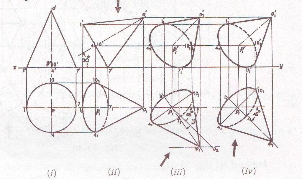
279 Problem 12: Draw the projections of a cone, base 75 mm diameter and axis 100 mm long, lying on the H. P. on one of its generators with the axis parallel to the V.P.
280
281 3. Projections of solids with axes inclined to both the H.P. and the VP.: The projections of a solid with its axis inclined to both the planes are drawn in three stages: (i) Simple position (ii) Axis inclined to one plane and parallel to the other (iii) Final position. The second and final positions may be obtained either by the alteration of the positions of the solid, i.e. the views, or by the alteration of reference lines.
282 Problem 13: A square prism, base 40 mm side and height 65 mm, has its axis inclined at 45 to the H.P. and has an edge of its base, on the H.P and inclined at 30 o to the V.P. Draw its projections.
283
284 Problem 14: Draw the projections of a cone, base 45 mm diameter and axis 50 mm long, when it is resting on the ground on a point on its base circle with (a) the axis making an angle of 30 with the H.P. and 45 with the VP; (b) the axis making an angle of 30 with the H.P. and its top view making 45 with the V.P.
285
286 Problem 14: A pentagonal pyramid, base 25 mm side and axis 50 mm long has one of its triangular faces in the V.P. and the edge of the base contained by that face makes an angle of 30 with the H.P. Draw its projections.
287
288 Problem 15: Draw the projections of a cube of 25 mm long edges resting on the H.P on one of its corners with a solid diagonal perpendicular to the V.P.
289
290 Problem 16: A pentagonal prism is resting on one of the corners of its base on the H.P. The longer edge containing that corner is inclined at 45 to the H.P. and the vertical plane containing that edge and the axis are inclined at 30 to the V.P. Draw the projections of the solid. Also, draw the projections of the solid when the plan of axis is inclined at 30 to xy. Take the side of base 45 mm and height 70 mm
291
292
293 1. A rectangular block 75 mm x 50 mm x 25 mm thick has a hole of 30 mm diameter drilled centrally through its largest faces. Draw the projections when the block has its 50 mm long edge parallel to the H.P and perpendicular to the V.P. and has the axis of the hole inclined at 60' to the H.P. 2. Draw the projections of a square pyramid having one of its triangular faces in the V.P and the axis parallel to and 40 mm above the H.P. Base 30 mm side; axis 75 mm long. 3. A cylindrical block, 75 mm diameter and 25 mm thick, has a hexagonal hole of 25 mm side, cut centrally through its flat faces. Draw three views of the block when it has its flat faces vertical and inclined at 30 to the V.P. and two faces of the hole parallel to the H.P.
294 4. Draw three views of an earthen flower pot, 25 cm diameter at the top,15 cm diameter at the bottom, 30 cm high and 2.5 cm thick, when its axis makes an angle of 30 with the vertical. 5. A tetrahedron of 75 mm long edges has one edge parallel to the H.P. and inclined at 45 to the V.P while a face containing that edge is vertical. Draw its projections. 6. A hexagonal prism, base 30 mm side and axis 75 mm long, has an edge of the base parallel to the H.P and inclined at 45 to the V.P. Its axis makes an angle of 60 with the H.P. Draw its projections.
295 7. A pentagonal prism is resting on a corner of its base on the ground with a longer edge containing that corner inclined at 45 to the H.P and the vertical plane containing that edge and the axis inclined at 30 to the V.P. Draw its projections. Base 40 mm side; height 65 mm.y 8. Draw three views of a cone, base 50 mm diameter and axis 75 mm long, having one of its generators in the V.P and inclined at 30 to the H.P., the apex being in the H.P. 9. A square pyramid, base 40 mm side and axis 90 mm long, has a triangular face on the ground and the vertical plane containing the axis makes an angle of 45 with the V.P. Draw its projections.
296 10. A frustum of a pentagonal pyramid, base 50 mm side, top 25 mm side and axis 75 mm long, is placed on its base on the ground with an edge of the base perpendicular to the V.P. Draw its projections. Project another top view on a reference line parallel to the line which shows the true length of the slant edge. From this top view, project a front view on an auxiliary vertical plane inclined at 45 to the top view of the axis. 11. Draw the projections of a cone, base 50 mm diameter and axis 75 mm long, lying on a generator on the ground with the top view of the axis making an angle of 45 with the V.P. 12. The front view, incomplete top view and incomplete auxiliary top view of a casting are given in fig Draw all the three views completely in the third-angle projection.
297 SECTIONS OF SOLIDS Invisible features of an object are shown by dotted lines in their projected views. But when such features are too many, these lines make the views more complicated and difficult to interpret. In such cases, it is customary to imagine the object as being cut through or sectioned by planes. The part of the object between the cutting plane and the observer is assumed to be removed and the view is then shown in section.
298 The imaginary plane is called a section plane or a cutting plane. The surface produced by cutting the object by the section plane is called the section. It is indicated by thin section lines uniformly spaced and inclined at 45. The projection of the section along with the remaining portion of the object is called a sectional view. Sometimes, only the word section is also used to denote a sectional view.
299 True shape of a section: The projection of the section on a plane parallel to the section plane will show the true shape of the section. Thus, when the section plane is parallel to the H.P or the ground, the true shape of the section will be seen in sectional top view. When it is parallel to the V.P, the true shape will be visible in the sectional front view. But when the section plane is inclined, the section has to be projected on an auxiliary plane parallel to the section plane, to obtain its true shape. When the section plane is perpendicular to both the reference planes, the sectional side view will show the true shape of the section.
300 These are illustrated according to the position of the section plane with reference to the principal planes as follows: (a) Section plane parallel to the V.P. (b) Section plane parallel to the H.P. (c) Section plane perpendicular to the H.P. and inclined to the V.P. (d) Section plane perpendicular to the V.P. and inclined to the H.P.
301 Problem 01: A cube of 35 mm long edges is resting on the H.P. on one of its faces with a vertical face inclined at 30 to the V.P. It is cut by a section plane parallel to the V.P. and 9 mm away from the axis and further away from the V.P. Draw its sectional front view and the top view.
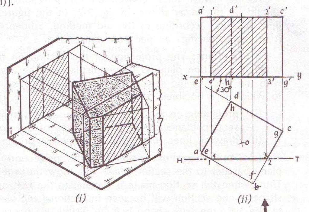
302
303 Problem 02: A cube in the same position as in problem 01 is cut by a section plane, perpendicular to the V.P., inclined at 45 to the H.P. and passing through the top end of the axis. (i) Draw its front view, sectional top view and true shape of the section. (ii) Project another top view on an auxiliary plane, parallel to the section plane.
304
305 Problem 03: A square pyramid, base 40 mm side and axis 65 mm long, has its base on the H.P. and all the edges of the base equally inclined to the V.P. It is cut by a section plane, perpendicular to the V.P., inclined at 45 to the H.P. and bisecting the axis. Draw its sectional top view, sectional side view and true shape of the section.
306
307 Problem 04: A hexagonal pyramid, base 30 mm side and axis 65 mm long, is resting on its base on the H.P. with two edge parallel to the V.P. It is cut by a section plane, perpendicular to the V.P. inclined at 45 to the H.P. and intersecting the axis at a point 25 mm above the base. Draw the front view, sectional top view, sectional side view and true shape of the section.
308
309 Problem 05: A hexagonal pyramid, base 30 mm side and axis 75 mm long, resting on its base on the H.P. with two of its edges parallel to the V.P. is cut by two section planes, both perpendicular to the V.P. The horizontal section plane cuts the axis at a point 35 mm from the apex. The other plane which makes an angle of 45 with the H.P., also intersects the axis at the same point. Draw the front view, sectional top view, true shape of the section.
310
311 Problem 06: A cylinder, 55 mm diameter and 65 mm long, has its axis parallel to both the H.P. and the V.P. It is cut by a vertical section plane inclined at 30 to the V.P., so that the axis is cut at a point 25 mm from one of its ends and both the bases of the cylinder are partly cut. Draw its sectional front view and true shape of the section.
312
313 Problem 06: A cone, base 75 mm diameter and axis 80 mm long is resting on its base on the H.P. It is cut by a section plane perpendicular to the V.P., inclined at 45 to the H.P. and cutting the axis at a point 35 mm from the apex. Draw its front view, sectional top view, sectional side view and true shape of the section.
314
315
316 Problem 07: The cone in same position as in problem 06, is cut by a section plane perpendicular to the V.P. and parallel to and 12 mm away from one of its end generators. Draw its front view sectional top view and true shape of the section.
317
318 EXERCISE: XIV 1. A cube of 50 mm long edges is resting on the H.P with a vertical face inclined at 30 to the V.P. It is cut by a section plane, perpendicular to the V.P., inclined at 30 to the H.P and passing through a point on the axis, 38 mm above the H.P. Draw the sectional top view, true shape of the section and development of the surface of the remaining portion of the cube. 2. A hexagonal prism, side of base 35 mm and height 75 mm is resting on one of its corners on the H.P with a longer edge containing that corner inclined at 60 to the H.P and a rectangular face parallel to the V.P. A horizontal section plane cuts the prism in two equal halves. (i) Draw the front view and sectional top view of the cut prism. (ii) Draw another top view on an auxiliary inclined plane which makes an angle of 45 with the H.P.
319 3. A pentagonal prism, side of base 50 mm and length 100 mm has a rectangular face on the H.P. and the axis parallel to the V.P. It is cut by a vertical section plane, the H.T. of which makes an angle of 30 with xy and bisects the axis. Draw the sectional front view, top view and true shape of the section. 4. A hollow square prism, base 50 mm side (outside), length 75 mm and thickness 9 mm is lying on the H.P. on one of its rectangular faces, with the axis inclined at 30 to the V.P. A section plane, parallel to the V.P. cuts the prism, intersecting the axis at a point 25 mm from one of its ends. Draw the top view and sectional front view of the prism.
320 5. A cylinder, 65 mm diameter and 90 mm long, has its axis parallel to the H.P and inclined at 30 to the V.P. It is cut by a vertical section plane in such a way that the true shape of the section is an ellipse having the major axis 75 mm long. Draw its sectional front view and true shape of the section. 6. A cube of 65 mm long edges has its vertical faces equally inclined to the V.P. It is cut by a section plane, perpendicular to the V.P., so that the true shape of the section is a regular hexagon. Determine the inclination of the cutting plane with the H.P and draw the sectional top view and true shape of the section.
321 7. A vertical hollow cylinder, outside diameter 60 mm, length 85 mm and thickness 9 mm is cut by two section planes which are normal to the V.P and which intersect each other at the top end of the axis. The planes cut the cylinder on opposite sides of the axis and are inclined at 30 and 45 respectively to it. Draw the front view, sectional top view and auxiliary sectional top views on planes parallel to the respective section planes. 8. A square pyramid, base 50 mm side and axis 75 mm long, is resting, on the H.P on one of its triangular faces, the top view of the axis making an angle of 30 with the V.P. It is cut by a horizontal section plane, the V.T. of which intersects the axis at a point 6 mm from the base. Draw the front view, sectional top view.
322 9. A pentagonal pyramid, base 30 mm side and axis 75 mm long, has its base horizontal and an edge of the base parallel to the V.P. It is cut by a section plane, perpendicular to the V.P., inclined at 60 to the H.P and bisecting the axis. Draw the front view and the top view, when the pyramid is tilted so that it lies on its cut-face on the ground with the axis parallel to the V.P. Show the shape of the section by dotted lines. 10. A tetrahedron of 65 mm long edges is lying on the H.P. on one of its faces, with an edge perpendicular to the V.P. It is cut by section plane which is perpendicular to the V.P. so that the true shape of the section is an isosceles triangle of base 50 mm long any altitude 40 mm. Find the inclination of the section plane with the H.P. and draw the front view, sectional top view and the true shape of the section.
323 11. A hexagonal pyramid, base 50 mm side and axis 100 mm long, is lying on the H.P. on one of its triangular faces with the axis parallel to the V.P. A vertical section plane the H.T. of which makes an angle of 30 with the reference line, passes through the centre of the base and cuts the pyramid, the apex being retained. Draw the top view, sectional front view, true shape of the section. 12. A cone, base 75 mm diameter and axis 75 mm long, has its axis parallel to the V.P. and inclined at 45 to the H.P. A horizontal section plane cuts the cone through the mid-point of the axis. Draw the front view, sectional top view and an auxiliary top view on a plane parallel to the axis.
324 13. A cone, base 65 mm diameter and axis 75 mm long, is lying on the H.P on one of its generators with the axis parallel to the V.P. A section plane which is parallel to the V.P. cuts the cone 6 mm away from the axis. Draw the sectional front view. 14. The cone in above problem 13 is cut by a horizontal section plane passing through the centre of the base. Draw the sectional top view and another top view on an auxiliary plane parallel to the axis of the cone.
325 UNIT-IV
326 DEVELOPMENT OF SURFACES Imagine that a solid is enclosed in a wrapper of thin material, such as paper. If this covering is opened out and laid on a flat plane, the flattened-out paper is the development of the solid. Thus, when surfaces of a solid are laid out on a plane, the figure obtained is called its development. The knowledge of development of surfaces is essential in many industries such as automobile, aircraft, ship building, packaging and sheet-metal work. In construction of boilers, bins, process-vessels, hoppers, funnels, chimneys etc., the plates are marked and cut according to the developments which, when folded, form the desired objects. Only the surfaces of polyhedra (such as prisms and pyramids) and single-curved surfaces (as of cones and cylinders) can be accurately developed. Warped and double-curved surfaces are undevelopable. These can however be approximately developed by dividing them up MYcsvtu into a Notes number of parts.
327 METHODS OF DEVELOPMENT: (i) Parallel-line development: It is employed in case of prisms and cylinders in which stretch-out-line principle is used. (ii) Radial-line development: It is used for pyramids and cones in which the true length of the slant edge or the generator is used as radius. (iii) Triangulation development: This is used to develop transition pieces. This is simply a method of dividing a surface into a number of triangles and transferring them into the development. (iv) Approximate method: It is used to develop objects of double curved or warped surfaces as sphere, paraboloid, ellipsoid, hyperboloid and helicoid.
328 DEVELOPMENTS OF LATERAL SURFACES OF RIGHT SOLIDS: Problem 01: Draw the development of the surface of the part P of the cube, the front view of which is shown in the figure. Name all the corners of the cube and also the points at which the edges are cut.
329
330
331 Problem 02: Draw the development of the surface of the part P of the cube shown in two views in the figure.
332 Problem 03:
333 Problem 04: Draw the development of the lateral surface of the part P of the pentagonal prism shown in two views in the figure.
334 Problem 05:
335
336 Problem 06:
337 Problem 07:
338 Problem 08:
339 Problem 09:
340 Problem 10:
341 Problem 11:
342 Calculate the subtended angle θ by the formula, θ = 360 x radius of the base circle slant height Problem 12:
343 Problem 13:
344 EXERCISE XV:
345
346 ISOMETRIC PROJECTION Isometric projection is a type of pictorial projection in which the three dimensions of a solid are not only shown in one view, but their actual sizes can be measured directly from it. If a cube is placed on one of its corners on the ground with a solid diagonal perpendicular to the V.P., the front view is the isometric projection of the cube.
347
348 CB, CD, CG Isometric axes Lines parallel to these axes Isometric lines Planes representing the faces Isometric planes Construct a square BQDP around BD as a diagonal. Then BP shows the true length of BA. In ABO, BA BO 1 COS30 BP 1 2 In PBO, O BO COS45 1 BA BP 3 2 Isometric length True length 11 O 2 3
349 Isometric scale:
350 Isometric projection v/s Isometric drawing (Isometric view)
351 Isometric drawing of planes or plane figures
352 Four centre method of drawing Isometric projection of Circle
353
354
355
356
357
358
359
360
361
362
363
364
365
366
367 Problem 01:
368 Problem 02:
369 Problem 03:
370 Problem 04:
371 Problem 05:
372 Problem 06:
373 Problem 07:
374 UNIT -V

375
ENGINEERING GRAPHICS (Engineering Drawing is the language of Engineers)
") ENGINEERING GRAPHICS (Engineering Drawing is the language of Engineers) UNIT 1 Conic Section (Ellipse, Parabola & Hyperbola) - Cycloids, epicycloids, hypocycloids & Involutes around circle and square scales
ENGINEERING GRAPHICS (Engineering Drawing is the language of Engineers) UNIT 1 Conic Section (Ellipse, Parabola & Hyperbola) - Cycloids, epicycloids, hypocycloids & Involutes around circle and square scales
ENGINEERING DRAWING. 1. Set squares are used to draw different angles. What is the angel a formed by the 45⁰ set square? Give a brief answer.
 ENGINEERING DRAWING 1. Set squares are used to draw different angles. What is the angel a formed by the 45⁰ set square? Give a brief answer. 2. Which is the correct method of hatching a plane surface?
UNIT I PLANE CURVES AND FREE HAND SKETCHING CONIC SECTIONS
 UNIT I PLANE CURVES AND FREE HAND SKETCHING CONIC SECTIONS Definition: The sections obtained by the intersection of a right circular cone by a cutting plane in different positions are called conic sections
DELHI TECHNOLOGICAL UNIVERSITY ENGINEERING GRAPHICS LAB MANUAL
 DELHI TECHNOLOGICAL UNIVERSITY ENGINEERING GRAPHICS LAB MANUAL NAME: - ROLL NO: - GROUP: - BRANCH: - GROUP TEACHER: Page 1 www.rooplalrana.com 1 GENERAL INSTRUCTIONS FOR ENGG. GRAPHICS LAB 1) Students
B.E. 1 st year ENGINEERING GRAPHICS
 B.E. 1 st year ENGINEERING GRAPHICS Introduction 1. What is an Engineering Graphics and its requirements? A standardized graphic representation of physical objects and their relationship is called Engineering
Drawing sheet: - The various size of the drawing sheet used for engineering drawing as per IS Are listed in the table
 Dronacharya Group of Institutions, Greater Noida Computer Aided Engineering Graphics (CAEG) (NCE 151/251) List of Drawing Sheets: 1. Letter writing & Dimensioning. 2. Projection of Points & Lines. 3. Projection
BVRIT HYDERABAD College of Engineering for Women Department of Basic Sciences and Humanities
 BVRIT HYDERABAD College of Engineering for Women Department of Basic Sciences and Humanities Hand Out Subject Name: Engineering Graphics Prepared by (Faculty(s) Name): Mr. M Gopikrishna, Asst.Professor,
ENGINEERING CURVES (Week -2)
") UNIT 1(a) CONIC SECTIONS ENGINEERING CURVES (Week -2) These are non-circular curves drawn by free hand. Sufficient number of points are first located and then a smooth curve passing through them are drawn
UNIT 1(a) CONIC SECTIONS ENGINEERING CURVES (Week -2) These are non-circular curves drawn by free hand. Sufficient number of points are first located and then a smooth curve passing through them are drawn
Engineering Graphics. Practical Book. Government Engineering College Bhuj (Kutch - Gujarat) Department of Mechanical Engineering
 Department of Mechanical Engineering") Engineering Graphics Practical Book ASHISH J. MODI Department of Mechanical Engineering Government Engineering College Bhuj 370 001 (Kutch - Gujarat) SYLLABUS (AS PER GUJARAT TECHNOLOGICAL UNIVERSITY,
Engineering Graphics Practical Book ASHISH J. MODI Department of Mechanical Engineering Government Engineering College Bhuj 370 001 (Kutch - Gujarat) SYLLABUS (AS PER GUJARAT TECHNOLOGICAL UNIVERSITY,
(As per New Revised Syllabus of Anna University) Department of Mechanical Engineering. SATHYABAMA UNIVERSITY Jeppiaar Nagar, Chennai
 Department of Mechanical Engineering. SATHYABAMA UNIVERSITY Jeppiaar Nagar, Chennai") (1*,1((5,1* *5$3+,&6 (As per New Revised Syllabus of Anna University) Dr. S.RAMACHANDRAN, M.E., Ph.D. Professor & Head K. PANDIAN, M.E., E.V.V.RAMANAMURTHY, M.Tech., R. DEVARAJ, M.E., Associate Professors
(1*,1((5,1* *5$3+,&6 (As per New Revised Syllabus of Anna University) Dr. S.RAMACHANDRAN, M.E., Ph.D. Professor & Head K. PANDIAN, M.E., E.V.V.RAMANAMURTHY, M.Tech., R. DEVARAJ, M.E., Associate Professors
ORDINARY LEVEL PAST PAPERS
 ORDINARY LEVEL PAST PAPERS UNEB S4 1982 SECTION I PLANE GEOMETRY 1. (a) Construct a diagonal scale of 40mm to 10mm to read up to 20mm by 0.02mm. (b) Indicate on your scale the following readings. (i) 14.8mm.
GE ENGINEERING GRAPHICS
 ANNA UNIVERSITY, CHENNAI (REGULATION GE8152 - ENGINEERING GRAPHICS B.E SEMESTER I Lecture Tutorial Practical Marks Credits Total Hours 2 0 3 100 4 90 Mr.S.Gokul (Asst. Prof/Mech) Sri Eshwar College of
GOVERNMENT POLYTECHNIC, VALSAD MECHANICAL ENGINEERING DEPARTMENT ASSIGNMENT SUB: MECHANICAL DRAFTING (C321901) TERM:172
 TERM:172") GOVERNMENT POLYTECHNIC, VALSAD MECHANICAL ENGINEERING DEPARTMENT ASSIGNMENT SUB: MECHANICAL DRAFTING (C321901) TERM:172 1) When all the dimension are placed above the dimension line, it is called (a) Aligned
GOVERNMENT POLYTECHNIC, VALSAD MECHANICAL ENGINEERING DEPARTMENT ASSIGNMENT SUB: MECHANICAL DRAFTING (C321901) TERM:172 1) When all the dimension are placed above the dimension line, it is called (a) Aligned
M.V.S.R. ENGINEERING COLLEGE, NADERGUL HYDERABAD B.E. I/IV I - Internal Examinations (November 2014)
") Sub: Engineering Graphics Branches: Civil (1&2), IT-2 Time: 1 Hr 15 Mins Max. Marks: 40 Note: Answer All questions from Part-A and any Two from Part B. Assume any missing data suitably. 1. Mention any
Sub: Engineering Graphics Branches: Civil (1&2), IT-2 Time: 1 Hr 15 Mins Max. Marks: 40 Note: Answer All questions from Part-A and any Two from Part B. Assume any missing data suitably. 1. Mention any
SIDDHARTH GROUP OF INSTITUTIONS :: PUTTUR
 SIDDHARTH GROUP OF INSTITUTIONS :: PUTTUR Siddharth Nagar, Narayanavanam Road 517583 QUESTION BANK Subject Code : Engineering Graphics& Design Course & Branch : B.Tech ALL Year & Sem : I B.Tech & I Sem
Second Semester Session Shri Ramdeobaba College of Engineering & Management, Nagpur. Department of Mechanical Engineering
 Second Semester Session- 2017-18 Shri Ramdeobaba College of Engineering & Management, Nagpur. Department of Mechanical Engineering Engineering Drawing Practical Problem Sheet Sheet No.:- 1. Scales and
ISOMETRIC PROJECTION. Contents. Isometric Scale. Construction of Isometric Scale. Methods to draw isometric projections/isometric views
 ISOMETRIC PROJECTION Contents Introduction Principle of Isometric Projection Isometric Scale Construction of Isometric Scale Isometric View (Isometric Drawings) Methods to draw isometric projections/isometric
 RAKESH JALLA B.Tech. (ME), M.Tech. (CAD/CAM) Assistant Professor, Department Of Mechanical Engineering, CMR Institute of Technology. CONICS Curves Definition: It is defined as the locus of point P moving
NOTE: Topic No. 1, 8 and 9 of the above syllabus to be covered in Practical Hours.
 Subject Engineering Graphics Teaching scheme Theory Tutorial Practical Credits 2 0 4 6 Engineering Graphics syllabus 1. Introduction to Engineering Graphics, Drawing instruments and accessories, BIS SP
Set No - 1 I B. Tech I Semester Regular/Supplementary Examinations Jan./Feb ENGINEERING DRAWING (EEE)
") Set No - 1 I B. Tech I Semester Regular/Supplementary Examinations Jan./Feb. - 2015 ENGINEERING DRAWING Time: 3 hours (EEE) Question Paper Consists of Part-A and Part-B Answering the question in Part-A
Set No - 1 I B. Tech I Semester Regular/Supplementary Examinations Jan./Feb. - 2015 ENGINEERING DRAWING Time: 3 hours (EEE) Question Paper Consists of Part-A and Part-B Answering the question in Part-A
Chapter 5 SECTIONS OF SOLIDS 5.1 INTRODUCTION
 Chapter 5 SECTIONS OF SOLIDS 5.1 INTRODUCTION We have studied about the orthographic projections in which a 3 dimensional object is detailed in 2-dimension. These objects are simple. In engineering most
2. Line composed of closely and evenly spaced short dashes in a drawing represents
 1. Hidden lines are drawn as (a) dashed narrow lines (b) dashed wide lines (c) long-dashed dotted wide line (d) long-dashed double dotted wide line Ans: (a) 2. Line composed of closely and evenly spaced
ENGINEERING DRAWING
 Subject Code: R13109/R13 Set No - 1 I B. Tech I Semester Regular/Supplementary Examinations Jan./Feb. - 2015 ENGINEERING DRAWING (Common to ECE, EIE, Bio-Tech, EComE, Agri.E) Time: 3 hours Max. Marks:
Introduction CHAPTER Graphics: A Tool to Communicate Ideas
 CHAPTER 1 Introduction 1.1 Graphics: A Tool to Communicate Ideas Engineering graphics or drawing is the universal language of engineers. An engineer communicate his idea to others with the help of this
ENGINEERING DRAWING I Semester (AE/ ME/ CE) IA-R16
 IA-R16") INSTITUTE OF AERONAUTICAL ENGINEERING (Autonomous) Dundigal, Hyderabad -500 043 MECHANICAL ENGINEERING ENGINEERING DRAWING I Semester (AE/ ME/ CE) IA-R16 Prepared By Prof B.V.S. N. Rao, Professor, Mr.
INSTITUTE OF AERONAUTICAL ENGINEERING (Autonomous) Dundigal, Hyderabad -500 043 MECHANICAL ENGINEERING ENGINEERING DRAWING I Semester (AE/ ME/ CE) IA-R16 Prepared By Prof B.V.S. N. Rao, Professor, Mr.
B.E. 1 st Year Engineering Graphics ( )
") B.E. 1 st Year Engineering Graphics (2110013) Department of Mechanical Engineering Darshan Institute of Engg. & Tech., Rajkot Darshan Institute Of Engg. & Technology List Of Instruments SR NO. 1. Set-Square
B.E. 1 st Year Engineering Graphics (2110013) Department of Mechanical Engineering Darshan Institute of Engg. & Tech., Rajkot Darshan Institute Of Engg. & Technology List Of Instruments SR NO. 1. Set-Square
INSTITUTE OF AERONAUTICAL ENGINEERING
 Course Name Course Code Class Branch INSTITUTE OF AERONAUTICAL ENGINEERING Dundigal, Hyderabad - 500 043 MECHANICAL ENGINEERING TUTORIAL QUESTION BANK : ENGINEERING DRAWING : A10301 : I - B. Tech : Common
Engineering Graphics, Class 5 Geometric Construction. Mohammad I. Kilani. Mechanical Engineering Department University of Jordan
 Engineering Graphics, Class 5 Geometric Construction Mohammad I. Kilani Mechanical Engineering Department University of Jordan Conic Sections A cone is generated by a straight line moving in contact with
Multi-View Drawing Review
 Multi-View Drawing Review Sacramento City College EDT 300/ENGR 306 EDT 300 / ENGR 306 - Chapter 5 1 Objectives Identify and select the various views of an object. Determine the number of views needed to
6. Draw the isometric view of a cone 40 mm diameter and axis 55 mm long when its axis is horizontal. Draw isometric scale. [16]
![6. Draw the isometric view of a cone 40 mm diameter and axis 55 mm long when its axis is horizontal. Draw isometric scale. [16]](/thumbs/85/92603403.jpg "6. Draw the isometric view of a cone 40 mm diameter and axis 55 mm long when its axis is horizontal. Draw isometric scale. [16]") Code No: R05010107 Set No. 1 I B.Tech Supplimentary Examinations, Aug/Sep 2007 ENGINEERING GRAPHICS ( Common to Civil Engineering, Mechanical Engineering, Mechatronics, Metallurgy & Material Technology,
Code No: R05010107 Set No. 1 I B.Tech Supplimentary Examinations, Aug/Sep 2007 ENGINEERING GRAPHICS ( Common to Civil Engineering, Mechanical Engineering, Mechatronics, Metallurgy & Material Technology,
Scales. 1. Basic Information. 2. Types and important units. 3. Plain Scales (3 Problems) 4. Diagonal Scales - information
 4. Diagonal Scales - information") Contents 1. Scales 2. Engineering Curves - I 3. Engineering Curves - II 4. Loci of Points 5. Orthographic Projections - Basics 6. Conversion of Pictorial View into Orthographic Views 7. Projections of
Contents 1. Scales 2. Engineering Curves - I 3. Engineering Curves - II 4. Loci of Points 5. Orthographic Projections - Basics 6. Conversion of Pictorial View into Orthographic Views 7. Projections of
4. Draw the development of the lateral surface of the part P of the cylinder whose front view is shown in figure 4. All dimensions are in cm.
 Code No: Z0122 / R07 Set No. 1 I B.Tech - Regular Examinations, June 2009 ENGINEERING GRAPHICS ( Common to Civil Engineering, Mechanical Engineering, Chemical Engineering, Bio-Medical Engineering, Mechatronics,
Engineering Graphics- Basics.
 Engineering Graphics- Basics DRAWINGS: ( A Graphical Representation) The Fact about: If compared with Verbal or Written Description, Drawings offer far better idea about the Shape, Size & Appearance of
BHARATHIDASAN ENGINEERING COLLEGE MGR NAGAR, NATRAM PALLI. Department of Mechanical Engineering GE6152 ENGINEERING GRAPHICS NOTES
 BHARATHIDASAN ENGINEERING COLLEGE MGR NAGAR, NATRAM PALLI Department of Mechanical Engineering GE6152 ENGINEERING GRAPHICS NOTES GE6152 ENGINEERING GRAPHICS OBJECTIVES: concepts, ideas and design of Engineering
ENGINEERING DRAWING IM 09 AND GRAPHICAL COMMUNICATION
 IM SYLLABUS (2014) ENGINEERING DRAWING IM 09 AND GRAPHICAL COMMUNICATION SYLLABUS Engineering Drawing and Graphical Communication IM 09 (Available in September) Syllabus 1 Paper (3 hours) Aims The aims
Chapter 4 ORTHOGRAPHIC PROJECTION
 Chapter 4 ORTHOGRAPHIC PROJECTION 4.1 INTRODUCTION We, the human beings are gifted with power to think. The thoughts are to be shared. You will appreciate that different ways and means are available to
CHAPTER 01 PRESENTATION OF TECHNICAL DRAWING. Prepared by: Sio Sreymean
 CHAPTER 01 PRESENTATION OF TECHNICAL DRAWING Prepared by: Sio Sreymean 2015-2016 Why do we need to study this subject? Effectiveness of Graphics Language 1. Try to write a description of this object. 2.
UNIT I PLANE CURVES AND FREE HAND SKETCHING 15
 Importance of graphics in engineering applications Use of drafting instruments BIS conventions and specifications Size, layout and folding of drawing sheets Lettering and dimensioning. UNIT I PLANE CURVES
Technical Drawing Paper 1 - Higher Level (Plane and Solid Geometry)
") Coimisiún na Scrúduithe Stáit State Examinations Commission 2008. M81 Leaving Certificate Examination 2008 Technical Drawing Paper 1 - Higher Level (Plane and Solid Geometry) (200 Marks) Friday 13 June
Coimisiún na Scrúduithe Stáit State Examinations Commission 2008. M81 Leaving Certificate Examination 2008 Technical Drawing Paper 1 - Higher Level (Plane and Solid Geometry) (200 Marks) Friday 13 June
ENGINEERING DRAWING I
 INSTITUTE OF ENGINEERING DEPARTMENT OF MECHANICAL ENGINEERING ENGINEERING DRAWING I [TUTORIAL SHEETS] 1 CONTENTS Sheet No. 1: Technical Lettering 3 Sheet No. 2: Plane Geometrical Construction 5 Sheet No.
Solutions to Exercise problems
 Brief Overview on Projections of Planes: Solutions to Exercise problems By now, all of us must be aware that a plane is any D figure having an enclosed surface area. In our subject point of view, any closed
Multiviews and Auxiliary Views
 Multiviews and Auxiliary Views Multiviews and Auxiliary Views Objectives Explain orthographic and multiview projection. Identifying the six principal views. Apply standard line practices to multiviews
Contents. Notes on the use of this publication
 Contents Preface xxiii Scope Notes on the use of this publication xxv xxvi 1 Layout of drawings 1 1.1 General 1 1.2 Drawing sheets 1 1.3 Title block 2 1.4 Borders and frames 2 1.5 Drawing formats 2 1.6
CE 100 Civil Engineering Drawing Sessional (Lab Manual)
") CE 100 Civil Engineering Drawing Sessional (Lab Manual) Department of Civil Engineering Ahsanullah University of Science and Technology November, 2017 1 Preface This course is designed to provide civil
CE 100 Civil Engineering Drawing Sessional (Lab Manual) Department of Civil Engineering Ahsanullah University of Science and Technology November, 2017 1 Preface This course is designed to provide civil
Copyrighted Material. Copyrighted Material. Copyrighted. Copyrighted. Material
 Engineering Graphics ORTHOGRAPHIC PROJECTION People who work with drawings develop the ability to look at lines on paper or on a computer screen and "see" the shapes of the objects the lines represent.
3. The dimensioning SYMBOLS for arcs and circles should be given:
 Draft Student Name: Teacher: District: Date: Wake County Test: 9_12 T and I IC61 - Drafting I Test 2 Description: 4.08 Dimensioning Form: 501 1. The MINIMUM amount of space between two, ADJACENT DIMENSION
Course Title: ENGINEERING GRAPHICS-I Course Code: 15ME12D. Type of course: Lectures & Practice Total Contact Hours: 78
 Course Title: ENGINEERING GRAPHICS-I Course Code: 15ME12D Credits (L:T:P) : 0:2:4 Core/ Elective: Core Type of course: Lectures & Practice Total Contact Hours: 78 CIE- 25 Marks SEE 100 Marks (***(Common
David Anderson. Gill & Macmillan
 One Volume Edition David nderson 3 and 4 Online Worksheets Ideal as homework exercises Will save students time as the problems are already set up on the page Worksheets are referenced in the text The material
Student Name: Teacher: Date: District: Rowan. Assessment: 9_12 T and I IC61 - Drafting I Test 1. Description: Unit C - Sketching - Test 2.
 Student Name: Teacher: Date: District: Rowan Assessment: 9_12 T and I IC61 - Drafting I Test 1 Description: Unit C - Sketching - Test 2 Form: 501 1. The most often used combination of views includes the:
APJ ABDUL KALAM TECHNOLOGICAL UNIVERSITY SECOND SEMESTER B.TECH DEGREE EXAMINATION, MAY PART A Answer ANY Two questions. 10 marks each.
 B B2B111 Pages: 2 Reg. No. Name: SECOND SEMESTER B.TECH DEGREE EXAMINATION, MAY 2017 Max.Marks:50 Course Code: BE110 Duration:3Hours Answer ANY Two questions. 10 marks each. 1. A line AB 100 mm long and
ENGINEERING DRAWING LECTURE 4
 ENGINEERING DRAWING LECTURE 4 Conventions Convention or Code: The representation of any matter by some sign or mark on the drawing is known as convention or code. The convention make the drawing simple
SIMILARLY IN CASE OF TINY OBJECTS DIMENSIONS MUST BE INCREASED FOR ABOVE PURPOSE. HENCE THIS SCALE IS CALLED ENLARGING SCALE. FOR FULL SIZE SCALE R.
 DIMENSIONS OF LARGE OBJECTS MUST BE REDUCED TO ACCOMMODATE ON STANDARD SIZE DRAWING SHEET.THIS REDUCTION CREATES A SCALE OF THAT REDUCTION RATIO, WHICH IS GENERALLY A FRACTION.. SUCH A SCALE IS CALLED
UNIT 5a STANDARD ORTHOGRAPHIC VIEW DRAWINGS
 UNIT 5a STANDARD ORTHOGRAPHIC VIEW DRAWINGS 5.1 Introduction Orthographic views are 2D images of a 3D object obtained by viewing it from different orthogonal directions. Six principal views are possible
Change of position method:-
 Projections of Planes PROJECTIONS OF PLANES A plane is a two dimensional object having length and breadth only. Thickness is negligible. Types of planes 1. Perpendicular plane which have their surface
Chapter 2: Dimensioning Basic Topics Advanced Topics Exercises
 Chapter 2: Dimensioning Basic Topics Advanced Topics Exercises Dimensioning: Basic Topics Summary 2-1) Detailed Drawings 2-2) Learning to Dimension 2-3) Dimension Appearance and Techniques. 2-4) Dimensioning
LECTURE NOTES skyupsmedia HYDRAULIC MACHINES II B. Tech I semester (JNTUH-R13) I B.TECH. JNTU (R16)
 I B.TECH. JNTU (R16)") LECTURE NOTES ON MECHANICS ENGINEERING OF FLUIDS DRAWING AND HDRAULIC MACHINES II B. Tech I semester (JNTUH-R13) I B.TECH. JNTU (R16) s ENGINEERING DRAWING I Semester: AE / CE / ME Course Code Category
LECTURE NOTES ON MECHANICS ENGINEERING OF FLUIDS DRAWING AND HDRAULIC MACHINES II B. Tech I semester (JNTUH-R13) I B.TECH. JNTU (R16) s ENGINEERING DRAWING I Semester: AE / CE / ME Course Code Category
TIME SCHEDULE. Module Topic Periods 1 Importance of Engineering Graphics Drawing Instruments Drawing Standards Lettering and Numbering
 COURSE TITLE : ENGINEERING GRAPHICS (First Semester) COURSE CODE : COURSE CATEGORY : F PERIODS/WEEK : 3 PERIODS/SEMESTER : 54 CREDITS : Examination in the Second Semester RATIONALE: Engineering Graphics
Multiview Drawing. Definition: Graphical representation of a 3- dimensional object on one plane (sheet of paper) using two or more views.
 using two or more views.") Multiview Drawing Definition: Graphical representation of a 3- dimensional object on one plane (sheet of paper) using two or more views. Multiview Drawing Another name for multiview drawing is orthographic
Multiview Drawing Definition: Graphical representation of a 3- dimensional object on one plane (sheet of paper) using two or more views. Multiview Drawing Another name for multiview drawing is orthographic
Chapter 1 Overview of an Engineering Drawing
 Chapter 1 Overview of an Engineering Drawing TOPICS Graphics language Engineering drawing Projection methods Orthographic projection Drawing standards TOPICS Traditional Drawing Tools Lettering Freehand
11/12/2015 CHAPTER 7. Axonometric Drawings (cont.) Axonometric Drawings (cont.) Isometric Projections (cont.) 1) Axonometric Drawings
 Axonometric Drawings (cont.) Isometric Projections (cont.) 1) Axonometric Drawings") CHAPTER 7 1) Axonometric Drawings 1) Introduction Isometric & Oblique Projection Axonometric projection is a parallel projection technique used to create a pictorial drawing of an object by rotating the
CHAPTER 7 1) Axonometric Drawings 1) Introduction Isometric & Oblique Projection Axonometric projection is a parallel projection technique used to create a pictorial drawing of an object by rotating the
Student Name: Teacher: Date: District: Rowan. Assessment: 9_12 T and I IC61 - Drafting I Test 2. Description: Drafting 1 - Test 6.
 Student Name: Teacher: Date: District: Rowan Assessment: 9_12 T and I IC61 - Drafting I Test 2 Description: Drafting 1 - Test 6 Form: 501 1. 2X on a hole note means: A. Double the size of the hole. B.
ENGINEERING DRAWING INTRODUCTION
 ENGINEERING DRAWING INTRODUCTION Drawing is the graphical language of engineers which is built upon certain basic principles and standards. A good drawing can be prepared making use of these principles
ENGINEERING GRAPHICS ESSENTIALS. (A Text and Lecture Aid) Second Edition. Kirstie Plantenberg University of Detroit Mercy SDC PUBLICATIONS
 Second Edition. Kirstie Plantenberg University of Detroit Mercy SDC PUBLICATIONS") ENGINEERING GRAPHICS ESSENTIALS (A Text and Lecture Aid) Second Edition Kirstie Plantenberg University of Detroit Mercy SDC PUBLICATIONS Schroff Development Corporation www.schroff.com www.schroff-europe.com
ENGINEERING GRAPHICS ESSENTIALS (A Text and Lecture Aid) Second Edition Kirstie Plantenberg University of Detroit Mercy SDC PUBLICATIONS Schroff Development Corporation www.schroff.com www.schroff-europe.com
Pre Calc. Conics.
 1 Pre Calc Conics 2015 03 24 www.njctl.org 2 Table of Contents click on the topic to go to that section Review of Midpoint and Distance Formulas Intro to Conic Sections Parabolas Circles Ellipses Hyperbolas
Engineering Graphics. Class 2 Drafting Instruments Mohammad Kilani
 Engineering Graphics Class 2 Drafting Instruments Mohammad Kilani Drafting Instruments A Design is as good as its instruments A engineering drawing is a highly stylized graphic representation of an idea.
2010 Academic Challenge
 2010 Academic Challenge ENGINEERING GRAPHICS TEST STATE FINALS This Test Consists of 40 Questions Engineering Graphics Test Production Team Ryan K. Brown, Illinois State University Author/Team Leader Jacob
ORTHOGRAPHIC PROJECTION
 ORTHOGRAPHIC PROJECTION INTRODUCTION Any object has three dimensions, that is, length, width and thickness. A projection is defined as a representation of an object on a two dimensional plane. The projections
A Concise Introduction to Engineering Graphics
 A Concise Introduction to Engineering Graphics Fourth Edition Including Worksheet Series A Timothy J. Sexton, Professor Department of Industrial Technology Ohio University BONUS Book on CD: TECHNICAL GRAPHICS
(Ans:d) a. A0 b. A1 c. A2 d. A3. (Ans:b) (Ans:a) (Ans:d) (Ans:d)
 a. A0 b. A1 c. A2 d. A3. (Ans:b) (Ans:a) (Ans:d) (Ans:d)") Multiple Choice Questions (MCQ) on Engineering Drawing (Instruments) The mini drafter serves the purpose of everything except a. Scales b. Set square c. Protractor d. Compass (Ans:d) During operation,
Multiple Choice Questions (MCQ) on Engineering Drawing (Instruments) The mini drafter serves the purpose of everything except a. Scales b. Set square c. Protractor d. Compass (Ans:d) During operation,
ENGINEERING GRAPHICS 1E9
 Lecture 3 Monday, 15 December 2014 1 ENGINEERING GRAPHICS 1E9 Lecture 3: Isometric Projections Lecture 3 Monday, 15 December 2014 2 What is ISOMETRIC? It is a method of producing pictorial view of an object
TPCT s College of Engineering, Osmanabad. Laboratory Manual. Engineering Graphics. For. First Year Students. Manual Prepared by B. G.
 TPCT s College of Engineering, Osmanabad Laboratory Manual Engineering Graphics For First Year Students Manual Prepared by B. G. Kadam Author COE, Osmanabad TPCT s College of Engineering Solapur Road,
Pre-Calc. Slide 1 / 160. Slide 2 / 160. Slide 3 / 160. Conics Table of Contents. Review of Midpoint and Distance Formulas
 Slide 1 / 160 Pre-Calc Slide 2 / 160 Conics 2015-03-24 www.njctl.org Table of Contents click on the topic to go to that section Slide 3 / 160 Review of Midpoint and Distance Formulas Intro to Conic Sections
ORTHOGRAPHIC PROJECTION
 ORTHOGRAPHIC PROJECTION C H A P T E R S I X OBJECTIVES 1. Recognize and the symbol for third-angle projection. 2. List the six principal views of projection. 3. Understand which views show depth in a drawing
Engineering Graphics & Technology. NQF Level 2. Sparrow Consulting LECTURER S GUIDE TVET FIRST
 Engineering Graphics & Technology NQF Level 2 Sparrow Consulting LECTURER S GUIDE TVET FIRST Engineering Graphics & Technology NQF Level 2 Lecturer s Guide M Conradie Engineering Graphics & Technology
Civil Engineering Drawing
 Civil Engineering Drawing Third Angle Projection In third angle projection, front view is always drawn at the bottom, top view just above the front view, and end view, is drawn on that side of the front
ENGINEERING DRAWING. UNIT III - Part A
 DEVELOPMENT OF SURFACES: ENGINEERING DRAWING UNIT III - Part A 1. What is meant by development of surfaces? 2. Development of surfaces of an object is also known as flat pattern of the object. (True/ False)
Orthographic Projection
 Orthographic Projection Why Orthographic Projection is used in technical drawing Orthographic projection is a method of producing a number of separate two-dimensional inter-related views, which are mutually
Course Title: Basics Engineering Drawing (Code: )
") GUJARAT TECHNOLOGICAL UNIVERSITY, AHMEDABAD, GUJARAT COURSE CURRICULUM Course Title: Basics Engineering Drawing (Code: 3300007) Diploma Programmes in which this course is offered Automobile Engineering,
GUJARAT TECHNOLOGICAL UNIVERSITY, AHMEDABAD, GUJARAT COURSE CURRICULUM Course Title: Basics Engineering Drawing (Code: 3300007) Diploma Programmes in which this course is offered Automobile Engineering,
Coimisiún na Scrúduithe Stáit State Examinations Commission. Leaving Certificate Marking Scheme. Design and Communication Graphics.
 Coimisiún na Scrúduithe Stáit State Examinations Commission Leaving Certificate 2016 Marking Scheme Design and Communication Graphics Higher Level Note to teachers and students on the use of published
Pre-Calc Conics
 Slide 1 / 160 Slide 2 / 160 Pre-Calc Conics 2015-03-24 www.njctl.org Slide 3 / 160 Table of Contents click on the topic to go to that section Review of Midpoint and Distance Formulas Intro to Conic Sections
DRAWING INSTRUMENTS AND THEIR USES
 Chapter - 1A DRAWING INSTRUMENTS AND THEIR USES Drawing Instruments are used to prepare neat and accurate Drawings. To a greater extent, the accuracy of the Drawings depend on the quality of instruments
2003 Academic Challenge
 Worldwide Youth in Science and Engineering 2003 Academic Challenge ENGINEERING GRAPHICS TEST - REGIONAL Engineering Graphics Test Production Team Ryan Brown, Illinois State University Author/Team Coordinator
This early Greek study was largely concerned with the geometric properties of conics.
 4.3. Conics Objectives Recognize the four basic conics: circle, ellipse, parabola, and hyperbola. Recognize, graph, and write equations of parabolas (vertex at origin). Recognize, graph, and write equations
JUNIOR CERTIFICATE 2009 MARKING SCHEME TECHNICAL GRAPHICS HIGHER LEVEL
 . JUNIOR CERTIFICATE 2009 MARKING SCHEME TECHNICAL GRAPHICS HIGHER LEVEL Sections A and B Section A any ten questions from this section Q1 12 Four diagrams, 3 marks for each correct label. Q2 12 2 marks
Philadelphia University Faculty of Engineering Mechanical Engineering Department
 Philadelphia University Faculty of Engineering Mechanical Engineering Department Basics of Engineering Drawing Manual Done by:- Eng. Laith R.I. Batarseh Eng. Hanan Khamis 2017 1 Table of contents SUBJECT
CONIC SECTIONS. Teacher's Guide
 CONIC SECTIONS Teacher's Guide This guide is designed for use with Conic Sections, a series of three programs produced by TVOntario, the television service of the Ontario Educational Communications Authority.
Graphical Communication
 Chapter 9 Graphical Communication mmm Becoming a fully competent engineer is a long yet rewarding process that requires the acquisition of many diverse skills and a wide body of knowledge. Learning most
ME 111: Engineering Drawing
 ME 111: Engineering Drawing Lecture # 01 Introduction For more detail, visit http://shilloi.iitg.ernet.in/~psr/ Indian Institute of Technology Guwahati Guwahati 781039 1 Syllabus 1. Importance of engineering
ENGINEERING GRAPHICS 1.0 Introduction Engineering Graphics Drawing as an art Artist Graphic design Engineering graphics engineering drawing
 ENGINEERING GRAPHICS 1.0 Introduction Engineering is the profession in which the knowledge of mathematics and science gained by study, experience and practice is applied with good judgment to develop a
Technical Graphics Higher Level
 Coimisiún na Scrúduithe Stáit State Examinations Commission Junior Certificate Examination 2005 Technical Graphics Higher Level Marking Scheme Sections A and B Section A Q1. 12 Four diagrams, 3 marks for
Standards of Learning Guided Practice Suggestions. For use with the Mathematics Tools Practice in TestNav TM 8
 Standards of Learning Guided Practice Suggestions For use with the Mathematics Tools Practice in TestNav TM 8 Table of Contents Change Log... 2 Introduction to TestNav TM 8: MC/TEI Document... 3 Guided
2003 Academic Challenge
 Worldwide Youth in Science and Engineering 2003 Academic Challenge ENGINEERING GRAPHICS TEST - SECTIONAL Engineering Graphics Test Production Team Ryan Brown, Illinois State University Author/Team Coordinator
You identified, analyzed, and graphed quadratic functions. (Lesson 1 5) Analyze and graph equations of parabolas. Write equations of parabolas.
 Analyze and graph equations of parabolas. Write equations of parabolas.") You identified, analyzed, and graphed quadratic functions. (Lesson 1 5) Analyze and graph equations of parabolas. Write equations of parabolas. conic section degenerate conic locus parabola focus directrix
You identified, analyzed, and graphed quadratic functions. (Lesson 1 5) Analyze and graph equations of parabolas. Write equations of parabolas. conic section degenerate conic locus parabola focus directrix
Sketching Fundamentals
 Sketching Fundamentals Learning Outcome When you complete this module you will be able to: Make basic engineering sketches of plant equipment. Learning Objectives Here is what you will be able to do when
Dimensioning. Dimensions: Are required on detail drawings. Provide the shape, size and location description: ASME Dimensioning Standards
 Dimensioning Dimensions: Are required on detail drawings. Provide the shape, size and location description: - Size dimensions - Location dimensions - Notes Local notes (specific notes) General notes ASME
C.2 Equations and Graphs of Conic Sections
 0 section C C. Equations and Graphs of Conic Sections In this section, we give an overview of the main properties of the curves called conic sections. Geometrically, these curves can be defined as intersections
ENGINEERING GRAPHICS
 ENGINEERING GRAPHICS Course Structure Units Topics Marks Unit I Plane Geometry 16 1 Lines, angles and rectilinear figures 2 Circles and tangents 3 Special curves: ellipse, parabola, involute, cycloid.
Unit-5 ISOMETRIC PROJECTION
 Unit-5 ISOMETRIC PROJECTION Importance Points in Isometric: 1. For drawing the isometric, the object must be viewed such that either the front -right or the left edges becomes nearest. 2. All vertical
ENGINEERING GRAPHICS UNIT V ISOMETRIC PROJECTION PERSPECTIVE PROJECTION
 ENGINEERING GRAPHICS UNIT V ISOMETRIC PROJECTION PERSPECTIVE PROJECTION 1.PICTORIAL PROJECTIONS To visualize the shape of the whole object in its 3- D form, all the two or three orthographic views of the
Design & Communication Graphics
 L.84/85 Design & Communication Graphics Marking Scheme Ordinary Pg. 3 Higher Pg. 12 2013 L.84/85_MS 1/20 2013 L.84/85_MS 2/20 SECTION A - Core - Answer Any Three of the questions on this A3 sheet A-1.