BVRIT HYDERABAD College of Engineering for Women Department of Basic Sciences and Humanities
|
|
|
- Shannon Ross
- 5 years ago
- Views:
Transcription

1 BVRIT HYDERABAD College of Engineering for Women Department of Basic Sciences and Humanities Hand Out Subject Name: Engineering Graphics Prepared by (Faculty(s) Name): Mr. M Gopikrishna, Asst.Professor, ME Mr. K Nagendra Kumar, Asst.Professor, ME Ms. V Sai Leela, Asst.Professor, ME Mr. M Gangadhar Tilak, Asst.Professor, ME Ms. A Ramya, Asst.Professor, ME Year and Sem, Department: I B.Tech - I Sem, ECE Unit I: Introduction to Engineering Drawing: Principles of Engineering Graphics and their Significance, Conic Sections including the Rectangular Hyperbola General method only. Cycloid, Epicycloid and Hypocycloid, Scales Plain & Diagonal. Important Points / Definitions: Engineering Graphics Engineering drawing is the language of engineers. It is meant for communicating his/her ideas, thoughts and designs to others. A drawing drawn by an engineer, having engineering knowledge, for the engineering purpose is an engineering drawing (or instrument drawing). Applications of Engineering Drawing Engineering drawing is an essential part of almost all engineering projects. Some important uses of engineering drawing are mentioned below: 1. It is used in ships for navigation. 2. For manufacturing of machines, automobiles etc. 3. For construction of buildings, roads, bridges, dams, electrical and telecommunication structures etc. 4. For manufacturing of electric appliances like TV, phone, computers etc. Various Software s used for drafting Auto CAD, ANSYS, PRO/E, Ideas, Unigraphics and hyper mesh etc. SCALES The proportion by which we either reduce or increase the actual size of the object on a drawing is known as scale. It is not possible always to make drawings of an object to its actual size as the extent of drawing paper is limited and also sometimes the objects are too small to make it clearly understandable by drawing its actual size in drawing paper. Scale is the technique by which one can represent an object comfortably as well as precisely within the extent of drawing paper. In other words, a scale is a measuring stick, graduated with different divisions to represent the corresponding actual distance according to some proportion. Numerically scales indicate the relation between the dimensions on drawing and actual dimensions of the objects. Page 1 of 56
2 Uses of scale To prepare reduced or enlarged size drawings. To set off dimensions. To measure distances directly. Sizes of Scales Full size scale Reducing scale Enlarging scale Full Size Scale The scale in which the actual measurements of the object are drawn to the same size on the drawing is known as full size scale. It is represented as 1:1 scale. If possible, drawing should be done in full scale. Reducing Scale The scale in which the actual measurements of the object are reduced to some proportion is known as reducing scale. The standard formats of reducing proportions are: 1:2 - drawing made to one-half of the actual size 1:5 - drawing made to one-fifth of the actual size 1:10 - drawing made to one-tenth of the actual size 1:50 - drawing made to one-fiftieth of the actual size 1:100 - drawing made to one-hundredth of the actual size Enlarging Scale The scale in which the actual measurements of the object are increased to some proportion is known as reducing scale. The standard formats of enlarging proportions are: 2:1- drawing made to twice the actual size 5:1- drawing made to five times the actual size 10:1 - drawing made to ten times the actual size Classification of Scales Plain Scales Diagonal Scales Comparative Scales Vernier Scales Chord Scales The first two types (plain and diagonal) of scales are usually used in engineering drawings. Plain Scale The scale that can measure one main unit and one sub-unit of the main unit or up to a fraction of 1 st decimal point of the main unit is known to be a plain scale. It is simply a line divided into a number of equal parts and the 1 st part is further sub-divided into small parts. Kilometers and Hectometers, Meters and Decimeters, Meters and 1/10 th of Meters etc. can be measured using plain scales. Page 2 of 56
3 Diagonal Scale The scale that can measure one main unit and two sub-units of the main unit or up to a fraction of 2 nd decimal point of the main unit is known to be a diagonal scale. It is so named because the 2 nd sub-unit or 2 nd decimal of main unit is obtained by the principle of diagonal division. Kilometers-Hectometers-Decameters, Decameters-Meters-Decimeters, Meters-1/10 th of Meters- 1/100 th of Meters etc. can be measured using diagonal scales. Following are the necessary information required for construction of a scale: The representative fraction (R.F.) of the scale. The unit or units to be presented. The maximum length to be measured. The Representative Fraction (R.F.) or Scale Factor (S.F.) The ratio of the distance on drawing paper of an object to the corresponding actual distance of the object is known as the representative fraction (R.F.) or the scale factor (S.F.). It is to be remembered that for finding RF the distances used for calculation must be in same unit. And being a ratio of same units, R.F. itself has no unit. Mathematically, Representative factor (R.F) = Length of an element in the drawing Actual length of the same element Length of scale = (R.F) X Max. Length to be measured Units of Measurement It is modern practice to use metric system of units in engineering drawing. However, sometimes British system is also used. It is important to have clear understanding about unit conversion in both system. Metric Units for Linear Measurement Measurement British Units for Linear 10millimeters(mm)=1centimeter(cm) 10centimeters(cm)=1decimeter (dm) 10 decimeters (dm)=1 meter (m) 10 meters (m) = 1 decameter (dam) 10decameters(dam)=1hectometer(hm) 10hectometers(hm)=1 kilometer (km) 1 League = 3 miles 1 mile = 8 furlongs 1 furlong = 10 chains 1 chain = 22 yards 1 yard = 3 feet 1 foot = 12 inches Metric Units for Area Measurement 100 square millimeters (mm 2 ) = 1 square centimeter (cm 2 ) 100 square centimeters (cm 2 ) = 1 square decimeter (dm square decimeters (dm 2 ) = 1 square meter (m 2 ) 100 square meters (m 2 ) = 1 acre (a) 100 acres (a) = 1 hectare 100 hectares = 1 square kilometer (km 2 ) Construction of Plain Scale Page 3 of 56

4 Following are the steps for constructing a plain scale 1. Find out the R.F., if not given directly. 2. Find out the length of scale = R. F. Actual length of object or Maximum length to be measured 3. Draw a straight line, preferably horizontal, of required length as found in previous step. 4. Divide the line into a number of divisions relating to the length of object and maximum length to be measured such that one segment represents one major unit. Avoid fractions, consider the next integer value. For instance, if maximum length to be measured is 6.2 km, then number of divisions will be Place mark 0 at the end of 1 st main division (Remember, not at the starting point of 1 st division) and mark the other divisions sequentially toward right as 1,2,3.. etc. 6. Divide the 1 st main division into a number of divisions such that each of these smallest division represents one sub-unit. For instance if the scale need to measure in feet and inches, number of minor divisions will be 12. On the other hand if the scale is to measure in centimeters and millimeters or in meters and 1/10 th of meter number of divisions will be Mark the sub-unit sequentially toward left as 1, 2, 3 etc. or 0.1, 0.2, 0.3. etc. If space is limited they can be marked after every 2 division like 0, 2,4,.. etc. 8. Mention the R.F. of the scale below the figure. 9. Mention the name of main unit and sub-unit either at below or at the respective ends of the scale. PROBLEM NO.1:- Draw a scale 1 cm = 1m to read decimeters, to measure maximum distance of 6 m. Show on it a distance of 4 m and 6 dm. CONSTRUCTION:- a) Calculate R.F. = Length of an element in the drawing Actual length of the same element R.F.= 1cm/ 1m = 1/100 Length of scale = R.F. X max. distance = 1/100 X 600 cm = 6 cm b) Draw a line 6 cm long and divide it in 6 equal parts. Each part will represent larger division unit. c) Sub divide the first part which will represent second unit or fraction of first unit. d) Place ( 0 ) at the end of first unit. Number the units on right side of Zero and sub divisions e) on left-hand side of Zero. Take height of scale 5 to 10 mm for getting a look of scale. f) After construction of scale mention it s RF and name of scale as shown. g) Show the distance 4 m 6 dm on it as shown. Principle of Diagonal Scales: Page 4 of 56


5 The principle of diagonal scale is to obtain any fractional part of a short line by following the diagonal division method. In this method we get fractional part of a line, say 1/9 th of length, 1/15 th of length etc. Let the given short line AB which is required to be divided into 12 equal parts. Erect a perpendicular BC of any suitable length and divide it into 12 equal parts. Join AC and draw lines 1-1, 2-2, 3-3 etc. parallel to AB at each division point. Thus dividing is complete indirectly.if you need 1/12 th of AB, 1-1 will be your required length. If you need 2/12 th of AB, 2-2 is your required length. Similarly 3-3 represents 3/12 th of AB, 4-4 represents 4/12 th of AB and so on. PROBLEM NO 2: The distance between Delhi and Agra is 200 km. In a railway map it is represented by a line 5 cm long. Find it s R.F. Draw a diagonal scale to show single km. And maximum 600 km. Indicate on it following distances. 1) 222 km 2) 336 km 3) 459 km 4) 569 km. CONSTRUCTION:- RF = 5 cm / 200 km = 1 / 40, 00, 000 Length of scale = 1 / 40, 00, 000 X 600 X 10 5 = 15 cm a) Draw a line 15 cm long. b) It will represent 600 km. Divide it in six equal parts.( each will represent 100 km.) c) Divide first division in ten equal parts. d) Each will represent 10 km. Draw a line upward from left end and mark 10 parts on it of any distance. Name those parts 0 to 10 as shown. e) Join 9 th sub-division of horizontal scale with 10 th division of the vertical divisions. f) Then draw parallel lines to this line from remaining sub divisions and complete diagonal scale. Page 5 of 56

6 ENGINEERING CURVES: Conic Sections:Sections of a right circular cone obtained by cutting the cone in different ways Depending on the position of the cutting plane relative to the axis of cone, three conic sections can be obtained ellipse, parabola and hyperbola An ellipse is obtained when a section plane A A, inclined to the axis cuts all the generators of the cone. A parabola is obtained when a section plane B B, parallel to one of the generators cuts the cone. Obviously, the section plane will cut the base of the cone. A hyperbola is obtained when a section plane C C, inclined to the axis cuts the cone on one side of the axis. A rectangular hyperbola is obtained when a section plane D D, parallel to the axis cuts the cone. Conic is defined as locus of a point moving in a plane such that the ratio of its distance from a fixed point (F) to the fixed straight line is always a constant. This ratio is called as eccentricity. Ellipse: eccentricity is always 1 Parabola: eccentricity is always=1 Hyperbola: eccentricity is >1 The fixed point is called the Focus The fixed line is called the Directrix Axis is the line passing though the focus and perpendicular to the directrix Vertex is a point at which the conic cuts its axis Ellipse, parabola, hyperbola can be construction by the following methods: Page 6 of 56
 Rectangle Method (a) Rectangle Method (b) Parallelogram method (b) Parallelogram method 4. Eccentricity method 4.")
7 ELLIPSE PARABOLA HYPERBOLA 1. Concentric Circle Method 1. Offset method 1. Intersecting arcs method 2. Arcs of Circle Method 2. Tangent method 2. Asymptotes method 3. Oblong Method 3. Oblong Method 3. Eccentricity method (a) Rectangle Method (a) Rectangle Method (b) Parallelogram method (b) Parallelogram method 4. Eccentricity method 4. Eccentricity method (general method) (general method) Cycloidal curves: A Cycloid is the path or Locus followed by a point on a circle when it moves a long a straight line without slipping. Construction of a Cycloid 1. Below is a description of how to construct a Cycloid for a point P on a circle as it rotates along a straight line without slipping. 2. Firstly draw the circle and a line from its base to the left or right. The line should be to the right if the circle is rotating clockwise, and to the left if the circle is rotating anticlockwise. 3. In this situation we are going to find the locus of a point P which lies at the bottom of the circle where it touches the straight line 4..Now divide the circle into an equal number of parts. Here we have used the set square to give us 12 equal divisions. 5. Taking the distance between any two of these points with your compass mark 12 off these distances along the base line along which the circle will rotate. Lable these points 0 to 12 as shown. When taking the distance between any two of the divisions of the circle you should add a little bit to the distance on your compass to account for the curve of the circle. 6. Project the new points (from C1 to C12) on to a line from the centre of the circle. 7. As the circle rotates along the line, point 1 on the circle will move to point 1 on the line, and therefore the center of the circle will now be at point C1. 8. Next project lines from the equal divisions of the circle parallel to the straight line. These are the height lines. 9. With your compass set to the radius of the circle, place the point of the compass on the point C1 and cut the height line coming from point 1 on the circle. Then repeat this for point C2 and height line 2, etc. until you reach point C12 and line Essentially what you have done is break up the continuous movement of the circle along the straight line into 12 sections and found the position of point P for each movement. 11. It would get very cluttered if you drew in every circle along the way. Page 7 of 56
, draw an arc PQ. The included angle θ = (r/r) x 360. With O as centre and OC as radius, draw an arc to represent locus of centre.")
8 Epicycloid: The cycloid is called Epicycloid when the generating circle rolls along the circumference of another circle outside it. Illustrates the generation of an epicycloid. With O as centre and radius OP (base circle radius), draw an arc PQ. The included angle θ = (r/r) x 360. With O as centre and OC as radius, draw an arc to represent locus of centre. Divide arc PQ in to 12 equal parts and name them as 1, 2,., 12. Join O1, O2, and produce them to cut the locus of centres at C1, C2,.C12. Taking C1 as centre, and radius equal to r, draw an arc cutting the arc through 1 at P1. Taking C2 as centre and with the same radius, draw an arc cutting the arc through 2 at P2Similarly obtain points P3, P3,., P12. Draw a smooth curve passing through P1, P2.., P12, which is the required epiclycloid. Hypocycloid Hypocycloid is the curve generated by a point on the circumference of a circle which rolls without slipping inside another circle. The construction of a hypocycloid is illustrated. With O as centre and radius OP (base circle radius), draw an arc PQ. The included angle θ = (r/r) x 360. With O as centre and OC as radius, draw an arc to represent locus of centre. Divide arc PQ in to 12 equal parts and name them as 1, 2,., 12. Join O1, O2,, O12 so as to cut the locus of centres at C1, C2,.C12. Taking C1 as centre, and radius equal to r, draw an arc cutting the arc through 1 at P1. Taking C2 as centre and with the same radius, draw an arc cutting the arc through 2 at P2. Similarly obtain points P3, P3,., P12. Draw a smooth curve passing through P1, P2.., P12, which is the required hypocycloid. Page 8 of 56
 Construct a diagonal scale of 1:25 to read meters, decimeters and centimeters and long enough to measure 4 m. mark on it a distance of 2.")
9 Construction of a hypocycloid. Questions: 1) Draw a scale with RF 1:50 to show meters and decimeters and long enough to measure up to 5 meters. Marks a distance of 2.7 meters on it. 2) Construct a diagonal scale of 1:25 to read meters, decimeters and centimeters and long enough to measure 4 m. mark on it a distance of 2.47m 3) Draw an ellipse with major axis 120 and minor axis 80 by concentric circles method. 4) Draw an epicycloid having the diameters of both directing and generating circles as 60. Mention a name to this curve. 5) Draw a hypocycloid, when the diameter of the directing circle is twice to the generating circle. Assume the diameter of the generating circle is 60. 6) A circle of 60 diameter is rolling inside a circle whose radius is 90. Draw the path traced by a point on the circumference of the disc which is initially in touch with the directing circle. Name the curve. Draw a tangent and normal at a distance of 50 from the directing circle. Unit II: Orthographic Projections: Principles of Orthographic Projections Conventions Projections of Points and Lines, Projections of Plane regular geometric figures. Auxiliary Planes. Important Points / Definitions: Solid Geometry deals with the representation of 1. Points 2. Lines 3. Plane surfaces and 4. Solids - in the form of "Projections" on 2D drawing sheet. The word "Projection" is of Latin origin and means to 'throw forward'. it possible to prepare engineering drawings of engineering components in their true shapes and sizes. Page 9 of 56
10 Principle of Projection: Projection is defined as an image of an object thrown forward on to a plane by means of straight lines or visual rays. Straight lines are drawn from various points on the contour of an object to meet a plane, the object is said to be projected on that plane. Theory of Projection: Following are the elements to be considered while obtaining a projection: 1. The object 4. The rays of sight / Line of sight 2. The Plane of Projection 5. The Line of projection / Projectors 3. The Point of sight / Eye / Observer Projectors: The line joining different points of the projection and the corresponding point of the object is known as "Projector" or "Line of Projection". Line of Sight: The line of joining different points of the projection and the eye of the observer or point of sight is known as the "Line of Sight" or "Visual ray". Plane of Projection: The transparent plane on which the projections are drawn is known as "Plane of Projection". View: The figure or image formed on the plane by the projection of all the faces of an object is called a "view". The size of the view depends on the distance from the observer to the plane and the distance from the plane to the object. Classification of Projections: 1. Pictorial Projections (3D) 2. Orthographic Projections (2D) a. Axonometric b. Oblique c. Perspective Projection Orthographic Projection: If the projectors are parallel to each other and perpendicular to the plane of projection is called "Orthographic Projection" and divided into axonometric (3D) and multi-view (2D) projections. Projection Methods: Multi-view projection is further classified into 4 types st Angle Projection 2. 2 nd Angle Projection 3. 3 rd Angle Projection 4. 4 th Angle Projection Universally either the 1 st angle projection or the 3 rd angle projection methods is followed for obtaining engineering drawings. The principal projection planes and quadrants used to create drawings are shown in figure. The object can be considered to be in any of the four quadrant. Page 10 of 56


11 1 st Angle Projection: The object is assumed to be positioned in the first quadrant and is shown in figure. i.e., between the projection planes and the observer. The views are obtained by projecting the images on the respective planes. 3 rd Angle Projection: The object is assumed to be in the third quadrant. i.e. the object behind vertical plane and below the horizontal plane. Placing the object in the third quadrant puts the projection planes between the viewer and the object and is shown in figure. Page 11 of 56


12 Following figure illustrates the difference between the 1 st angle & 3 rd angle projection. A summary of the difference between 1st and 3rd angle projections is shown in Table. The type of projection is obtained should be indicated symbolically in the space provided for the purpose in the title box of the drawing sheet. The symbol recommended by BIS is to draw the two sides of a frustum of a cone placed with its axis horizontal The left view is drawn. Page 12 of 56
.")
13 Projections of Points: A Point is defined as a geometrical element which has no dimensions. The position of a point in engineering drawing is defined with respect to its distance from the three principle planes. The point is assumed to be in the respective quadrant shown in figure 1(a). Orientations of a Point: 1. Point is situated above the H.P. and in front of the V.P. 2. Point is situated above the H.P. and behind the V.P. 3. Point is situated below the H.P. and behind the V.P. 4. Point is situated below the H.P. and in front of the V.P. 5. Point is situated in the H.P. and in front of the V.P. 6. Point is situated in the H.P. and behind the V.P. 7. Point is situated above H.P. and in the V.P. 8. Point is situated below the H.P. and in the V.P. 9. Point is situated on the XY line or reference line. Conventions used while drawing the projections of points: With respect to the 1 st angle projection of point P shown in below figure, Top views are represented by only small letters eg. p. Their front views are conventionally represented by small letters with dashes eg. p Profile or side views are represented by small letters with double dashes eg. p Projectors are shown as thin lines. The line of intersection of HP and VP is denoted as X-Y. The line of intersection of VP and PP is denoted as X1-Y1 Page 13 of 56
.")


14 Point in the First quadrant: Point is situated above the H.P. and in front of the V.P. Following figure shown the projections of a point P which is 40 mm in front of VP, 50 mm above HP, 30 mm in front of left profile plane (PP). Above figure 2 is showing the three planes and the projection of the point P after the planes have been rotated on to the vertical plane. Figure 3 shows the planes and the position of the points when the planes are partially rotated. The arrows indicate the direction of rotation of the planes. The three views after complete rotation of the planes is shown in figure 2. Figure 3. Projection of the point P on to the three projection planes after the planes are partially rotated. Page 14 of 56
15 The procedure of drawing the three views of the point P is shown in figure-4. Draw a thin horizontal line, XY, to represent the line of intersection of HP and VP. Draw X1Y1 line to represent the line of intersection of VP and PP. Draw the Top View (p). Draw the projector line Draw the Front View (p ). To project the right view on the left PP, draw a horizontal projector through p to intersect the 45 degree line at m. Through m draw a vertical projector to intersect the horizontal projector drawn through p at p. p is the right view of point P Fig 4 First angle multi-view drawing of the point P Questions: 1) Draw the positions of the following points. a. A is 35 below H.P., 15 in front of V.P. b. B is 30 below H.P., 66 behind V.P. c. C is 20 above H.P., 30 in front of V.P. 2) Point P is 50 mm from both the reference planes. Draw its projection in all possible positions. 3) A point R is 25 mm above H.P. and its top view is 30 below XY line. Draw its projections. State in which quadrant the point is situated. 4) A point L is lying in the first quadrant. The shortest distance of the point from XY line is 55 mm. If the point is 30 above H.P. Draw its projections and also find the distance to the point from V.P. Projections of Lines: A line is defined as a geometrical element which has only one dimension called length. Straight line is the Locus of a point, which moves linearly. Straight line is also the shortest distance between any two given points. The location of a line in projection quadrants is described by specifying the distances of its end points from the VP, HP and PP. Orientations of a Straight line: 1. Parallel to both the planes. 2. Parallel to one plane and perpendicular to the other. 3. Parallel to one plane and inclined to the other. 4. Inclined to both the planes. Projection of a line: The projection of a line can be obtained by projecting its end points on planes of projections and then connecting the points of projections. The projected length and inclination of a line, can be different compared to its true length and inclination. Page 15 of 56


16 Case 1. Line parallel to a plane When a line is parallel to a plane, the projection of the line on to that plane will be its true length. The projection of line AB lying parallel to thev.p. is shown in figure 5 as a b. Figure 5. Projection of line on VP. Line AB is parallel to VP. Case 2. Line inclined to a plane When a line is parallel to one plane and inclined to the other, The projection of the line on the plane to which it is parallel will show its true length. The projected length on the plane to which it is inclined will always be shorter than the true length. In figure 6, the line AB is parallel to VP and is inclined to HP. The angle of inclination of AB with HP is being θ degrees. Projection of line AB on VP is a b and is the true length of AB. The projection of line AB on HP is indicated as line ab. Length ab is shorter than the true length AB of the line. Figure 6. Projection of line AB parallel to VO and inclined to HP. Case 3. Projection of a line parallel to both HP and VP A line AB having length 80 mm is parallel to both HP and VP. The line is 70 mm above HP, 60 mm in front of VP. End B is 30 mm in front of right PP. To draw the projection of line AB, assume the line in the first quadrant. The projection points of AB on the vertical plane VP, horizontal plane HP and Right Profile plane PP is shown in figure 7(a). Since the line is parallel to both HP and VP, both the front view a'b' and the top view ab are in true lengths. Since the line is perpendicular to the right PP, the left side view of the line will be a point a (b ). After projection on to the projection planes, the planes are rotated such that all the three projection planes lie in the same planes. The multi-view drawing of line AB is shown in Figure 7(b). Page 16 of 56
17 Figure 7. Projection of line parallel to both HP and VP. Case 4. Line perpendicular to HP & parallel to VP A line AB of length 80 mm is parallel to VP and perpendicular to HP. The line is 80 mm in front of VP and 80 mm in front of right PP. The lower end of the line is 30 mm above HP. The projections of line AB shown in figure 4 can be obtained by the following method. Draw a line XY which is the intersection between VP and HP. Draw the front view a'b' = 80 mm perpendicular to the XY line, with the lower end b' lying 30 mm above the XY line. Project the top view of the line which will be a point a(b) at a distance of 60 mm below XY line. Since the line is 70 mm in front of the right PP draw the X1Y1 line at a distance of 70 mm on the right- side of the front view. Through O the point of intersection of XY and X1Y1, lines draw a 45 line. Draw the horizontal projector through a(b) to cut the 45 degree line at m. Draw the horizontal projectors through a' and b' to intersect the vertical projector drawn through m at a and b. a b is the left view of the line AB. Page 17 of 56

18 Figure 8. Projections of a line AB perpendicular to HP and parallel to VP. Line parallel to one plane and inclined to the other Case 5. Line parallel to VP and inclined to HP A line AB, 90 mm long is inclined at 30 to HP and parallel to VP. The line is 80 mm in front of VP. The lower end A is 30 mm above HP. The upper end B is 50 mm in front of the right PP. The projections of line AB shown in figure 9 can be obtained in the following manner. Mark a', the front view of the end A, 30 mm above HP. Draw the front view a b = 90 mm inclined at 30 to XY line. Project the top view ab parallel to XY line. The top view is 80 mm in front of VP. Draw the X1Y1 line at a distance of 50 mm from b'. Draw a 45 line through O. Draw the horizontal projector through the top view ab to cut the 45 line at m. Draw a vertical projector through m. Draw the horizontal projectors through a' and b' to intersect the vertical projector drawn through m at a and b. Connect a b which is the left side view. Page 18 of 56


19 (b) Figure 9. Projections of line AB parallel to VP and inclined to HP. Case 6. Line inclined to HP and VP When a line is inclined to both HP and VP, the apparent inclination of the line to both the projection planes will be different from the actual inclinations. Similarly the projected length of the lines on to the planes will not be the same as the true length f the line. The following notation will be used for the inclinations: Actual inclinations are θ degrees to HP and φ degrees to VP. Apparent Inclinations are α and β to reference line XY. Above figure Illustrates: AB = True Length = a ' b1 ' = ab2 Front View = Elevation = a ' b ' = a ' b2 ' Top View = Plan = ab = ab1 True angles = θ degrees to HP and φ degrees to VP. Apparent angles = View angles = α and β to XY line. Page 19 of 56
of the line and denoted by the letter H.")


20 Traces of a line A trace is a point of intersection of a line with reference planes, if extended necessary. When a line meets HP, the point at which the line meets or intersects the horizontal plane, is called horizontal trace (HT)of the line and denoted by the letter H. When a line meets VP, the point at which the line meets or intersects the vertical plane, is called vertical trace (VT) of the line and denoted by the letter V. When the line is parallel to both HP and VP, there will be no traces on the said planes. Trace of a line perpendicular to one plane and parallel to the other Since the line is perpendicular to one plane and parallel to the other, the trace of the line is obtained only on the plane to which it is perpendicular, and no trace of the line is obtained on the other plane to which it is parallel. Figures 2 and 3 illustrates the trace of a line parallel to VP and perpendicular to HP and parallel to HP and perpendicular to VP respectively. Figure 2. Trace of line parallel to VP and perpendicular to HP Figure 3. Trace of a line perpendicular to the VP and parallel to HP Traces of a line inclined to one plane and parallel to the other When the line is inclined to one plane and parallel to the other, the trace of the line is obtained only on the plane to which it is inclined, and no trace is obtained on the plane to which it is parallel. Figure 4 shows the horizontal trace of line AB which is in lined HP and parallel to VP Figure 4 Horizontal trace of line AB Page 20 of 56

 and Vertical Trace (V) of the line AB lie below XY line. Figure 6 Vertical trace and horizontal trace of line AB which is inclined to both H.P.")
21 Figure 5 Vertical trace of line AB Traces of a line inclined to both the planes Figure 6 shows the Vertical trace (V) and Horizontal Trace (H) of Line AB inclined at q to HP and Φ to VP. The line when extended intersects HP at H, the horizontal trace, but will never intersect the portion of VP above XY line, i.e. within the portion of the VP in the 1 st quadrant. Therefore VP is extended below HP such that when the line AB is produced it will intersect in the extended portion of VP at V, the vertical trace. In this case both horizontal trace (H) and Vertical Trace (V) of the line AB lie below XY line. Figure 6 Vertical trace and horizontal trace of line AB which is inclined to both H.P. & V.P. Questions: 1) Draw the projection of the line AB of length 75 long for the following positions when it is parallel to both the planes. a. End A is 20 above H.P. and B is 30 in front of V.P. b. End A is 40 above H.P. on B is on V.P. 2) Draw the projections of the line AB of 60 long for the following positions. a. Perpendicular to H.P., parallel to V.P. and 30 in front of V.P. The end A is 10 above H.P. b. Perpendicular to V.P., one of it end is 15 in front of V.P. and parallel to H.P. and 10 from it. 3) The top view of a 75 long line AB measures 65 mm, while the length of its front view is 50 mm. It's one end A is in the H.P and 12 mm in front of the VP. Draw the projections of AB and determine its inclinations with the H.P and the V.P. 4) The top view of a 75 long line AB measures 65 mm, while the length of its front view is 50 mm. It's one end A is in the H.P and 12 mm in front of the VP. Draw the projections of AB and determine its inclinations with the H.P and the V.P. 5) The front view of a line AB measures 65 and makes an angle of 45 with XY. A is in the H.P and the V.T of a line is15 mm below the H.P. The line is inclined at 30 to the V.P. Draw the projections of AB and find its true length and inclination with the H.P. Also locate its H.T. Page 21 of 56


22 Projections of Planes: A plane is a geometrical element which has 2 dimensions called length and breadth with negligible thickness. Planes are bounded by straight/curved linesregular plane surfaces are in which all the sides are equal. Orientation of Plane surface: A plane surface may be positioned in space with reference to the three principal planes of projection in any of the following positions: Parallel to one of the principal planes and perpendicular to the other two. Perpendicular to one of the principal planes and inclined to the other two. Inclined to all the three principal planes. A: Plane surface parallel to one plane and perpendicular to the other two Consider A triangular lamina placed in the first quadrant with its surface parallel to VP and perpendicular to both HP and left PP. a'b'c' is the front view, abc the top view and a b c the side view Since the plane is parallel to VP, the front view a'b'c' shows the true shape of the lamina. Since the lamina is perpendicular to both HP and PP, the top view and side views are seen as lines. Figure 1. Projections of a triangular lamina on the projection planes After projecting the triangular lamina on VP, HP and PP, both HP and PP are rotated about XY and X1Y1 lines, as shown in figure 2, till they lie in-plane with that of VP. Figure 2. Rotation of PP and HP after projection. B) Plane parallel to HP and perpendicular to both VP and PP A square lamina is placed in the first quadrant with its surface parallel to HP and perpendicular to both VP and left PP. Figure 4 (a) shows the views of the object when projected on to the three planes. Top view is shown as abcd, the front view Page 22 of 56
b (c ) andb (a )c (d ) respectively.")

23 as a (d )b (c ) and the side view as b (a )c (d ). Since the plane is parallel to the HP, its top view abcd will be in its true shape. Since the plane is perpendicular to VP and PP, its front and side views will be lines a (d )b (c ) andb (a )c (d ) respectively. After projecting the square lamina on VP, HP and PP, both HP and PP are rotated about XY and X1Y1 lines, as shown in figure 4(b), till they lie in-plane with that of VP. Figure 4. Lamina with its surface parallel to HP and perpendicular to both VP and PP. C) Plane parallel to PP and perpendicular to both HP and VP A pentagon lamina (plane surface) is placed in the first quadrant with its surface is parallel to left PP and perpendicular to both VP and HP. Figure 5 (a) shows the views of the object when projected on to the three planes. Side view is shown as a b c d e, the front view as b (c )a (d )e and the top view as a(b)e(c)d.since the plane is parallel to the PP, its side view a b c d e will be in its true shape. Since the plane is perpendicular to VP and HP, its front and side views will be projected as lines. After projecting the pentagon lamina on VP, HP and PP, both HP and PP are rotated about XY and X1Y1 lines, as shown in figure 5(b), till they lie in-plane with that of VP. Figure 5 pentagonal lamina with its surface parallel to PP and perpendicular to HP and VP. D) Plane surface perpendicular to one plane and inclined to the other two Draw the projections of a triangular lamina (plane surface) placed in the first quadrant with its surface is inclined at f to VP and perpendicular to the HP. Since the lamina is inclined to VP, it is also inclined to left PP at (90 - Φ). The triangular lamina ABC is projected onto VP, HP and left PP. a b c is the front view projected on on VP. a b c is the right view projected on left PP. Since lamina is inclined to VP and PP, front and side views are not in true shape. Since lamina is perpendicular to HP, its top view is projected as a line acb Page 23 of 56
 A square lamina with 40 side has its surface parallel to and 30 in front of the V.P. draw the projections, if one of its side is inclined at 30⁰ to the H.")
24 Figure 6. The projections of the triangular lamina Questions: 1) A hexagonal lamina with a 30 long side has one of the side s perpendiculars to the V.P. The surface of the lamina is parallel to and 15 above the H.P. draw its projections? 2) A square lamina with 40 side has its surface parallel to and 30 in front of the V.P. draw the projections, if one of its side is inclined at 30⁰ to the H.P. 3) A thin circular plate of 40 diameter having its plane vertical and inclined at 40 0 to V.P. Its center is 30 above H.P. and 35 in front of V.P. draw the projections. 4) A rectangular plane with 50 and 30 sides is perpendicular to both H.P and V.P. The longer edges are parallel to H.P and the nearest one is 20 above it. The shortest edge nearer to the V.P is 15 from it. Draw its projections 5) A thin hexagonal plane with 25 side rest on a corner in the H.P such that the surface is perpendicular to the H.P and inclined at 45⁰ to the V.P. draw its projections when two sides of the plane are perpendicular to the H.P. Page 24 of 56
25 UNIT III Projections of Regular Solids Auxiliary Views - Sections or Sectional views of Right Regular Solids Prism, Cylinder, Pyramid, Cone Auxiliary views Sections of Sphere. Projections of Regular Solids: Important Points / Definitions: A solid is a 3-D object having length, breadth and thickness and bounded by surfaces which may be either plane or curved, or combination of the two solids are classified under two main headings Polyhedron Solids of revolution A regular polyhedron is solid bounded only by plane surfaces (faces). Its faces are formed by regular polygons of same size and all dihedral angles are equal to one another. When faces of a polyhedron are not formed by equal identical faces, they may be classified into prisms and pyramids. SOLIDS To understand and remember various solids in this subject properly, those are classified & arranged in to two major groups. Group A Solids having top and base of same shape Group B Solids having base of some shape and just a point as a top, called apex. Cylinder Cone Prisms Pyramids Triangular Square Pentagonal Hexagonal Cube ( A solid having six square faces) Triangular Square Pentagonal Hexagonal Tetrahedron ( A solid having Four triangular faces) Prism: Prisms are polyhedron formed by two equal parallel regular polygons, end faces connected by side faces which are either rectangles or parallelograms. Some definitions regarding prisms Base and lateral faces: When the prism is placed vertically on one of its end faces, the end face on which the prism rests is called the base. Base edge/shorter edge: These are the sides of the end faces Axis it is the imaginary line connecting the end faces is called axis Page 25 of 56
26 Longer edge/lateral edges: These are the edges connecting the respective corners of the two end faces. Right prism A prism whose axis is perpendicular to its end face is called as a right prism.prisms are named according to the shape of their end faces, i.e, if end faces are triangular, prism is called a triangular prism. Oblique prism: It is the prism in which the axis is inclined to its base. Pyramids Pyramid is a polyhedron formed by a plane surface as its base and a number of triangles as its side faces, all meeting at a point, called vertex or apex. Axis the imaginary line connecting the apex and the centre of the base. Inclined/slant faces inclined triangular side faces Inclined/slant/longer edges the edges which connect the apex and the base corners. Right pyramid when the axis of the pyramid is perpendicular to its base. Oblique pyramid when the axis of the pyramid is inclined to its base. Solids of revolution When some of the plane figures are revolved about one of their sides solids of revolution is generated some of the solids of revolution are: 1. Cylinder: when a rectangle is revolved about one of its sides, the other parallel side generates a cylinder. 2. Cone: when a right triangle is revolved about one of its sides, the hypotenuse of the right triangle generates a cone. 3. Oblique cylinder: when a parallelogram is revolved about one of its sides, the other parallel side generates a cylinder. 4. Sphere: when a semi-circle is revolved about one of its diameter, a sphere is generated.. 5. Truncated and frustums of solids when prisms, pyramids, cylinders are cut by cutting planes, the lower portion of the solids (without their top portions) are called, either truncated or frustum of these solids. Some examples are shown in figure. Page 26 of 56

27 Visibility When drawing the orthographic views of an object, it will be required to show some of the hidden details as invisible. To distinguish the invisible portions from the visible ones, the invisible edges of the object are shown on the orthographic views by dashed lines. However, in practice, these lines of dashes conveniently and colloquially, but wrongly called as dotted lines. To identify the invisible portions of the object, a careful imaginative thinking is essential. Rules of visibility When viewing an object, the outline of the object is visible. Hence the outlines of all the views are shown by full lines. All the visible edges will be shown as solid lines as shown in figure. Figure shows the frustum of a pentagonal pyramid. Projections of solids placed in different positions The solids may be placed on HP in various positions 1. The way the axis of the solid is held with respect to HP or VP or both - Perpendicular to HP or VP Parallel to either HP or VP and inclined to the other Inclined to both HP and VP 2. The portion of the solid on which it lies on HP, except when it is freely suspended position. It can lie on HP on its base edge or a corner, or a lateral face, or apex. Axis of the solid perpendicular to HP A solid when placed on HP with its axis perpendicular to it, then it will have its base on HP. This is the simplest position in which a solid can be placed. When the solid is placed with the base on HP position, in the top view, the base will be projected in its true shape. Hence, when the base of the solid is on HP, the top view is drawn first and then the front view and the side views are projected from it. Figure shows a cylinder with its axis perpendicular to HP. There is only one position in which a cylinder or a cone may be placed with its base on HP. Page 27 of 56

28 Projections of a solid with the axis perpendicular to VP When a solid is placed with its axis perpendicular to VP, the base of the solid will always be perpendicular to HP and parallel to VP. Hence in the front view, base will be projected in true shape. Therefore, when the axis of the solid is perpendicular to VP, the front view is drawn first and then the top and side views are drawn from it. When a cylinder rests on HP with its axis perpendicular to VP, one of its generators will be on HP. Figure shows the Front view and Top view of a cylinder and cone resting on HP with their axes perpendicular to VP. In this case one of the points on the circumference of the base will be on XY. Axis of the solid inclined to HP and parallel to VP When a solid is placed on HP with its axis inclined to HP, the elemental portion of the solid that lies on HP depends upon the type of the solid. When a prism is placed on HP with its axis inclined to it, and then it will lies either on one of its base edges or on one of its corners on HP. When a pyramid is placed on HP with its axis inclined to HP, then we will have one of its base edges on HP or one of its base corners on HP or one of its slant edges on HP or one of its triangular faces on HP or an apex on HP. Page 28 of 56
 Change of position method: In this method, the solids are placed first in the simple position and then tilted successively in two or three")

29 Methods of drawing the projections of solids These are two methods for drawing the projections of solids: 1. Change of position method. 2. Auxiliary plane method (Change of reference-line method) Change of position method: In this method, the solids are placed first in the simple position and then tilted successively in two or three stages to obtain the final position. The following are some of the examples. Example 1 A cube of 30 mm side rests with one of its edges on HP such that one of the square faces containing that edge is inclined at 30 0 to HP and the edge on which it rests being inclined to 60 0 to VP. Draw its projections. Example 2: A cone of base 80 mm diameter and height 100 mm lies with one of its generators on HP and the axis appears to be inclined to VP at an angle of 40 0 in the top view. Draw its top and front views. Page 29 of 56

30 Auxiliary plane method: In this method, the line is always placed parallel to both HP and VP, and then two auxiliary planes are set up: one auxiliary plane will be perpendicular to VP and inclined at q to HP, i.e., AIP, and the other will be perpendicular to HP and inclined at f (true inclination) or b (apparent inclination) to VP Example: A frustum of regular hexagonal pyramid is standing on it s larger base on Hp with one base side perpendicular to VP. Draw it s FV & TV. Project it s Auxiliary TV on an AIP parallel to one of the slant edges showing TL. Base side is 50 mm long, top side is 30 mm long and 50 mm is height of frustum. Example :A hexagonal prism of base side 30 mm long and axis 40 mm long, is standing on Hp on its base with one base edge // to VP.A tetrahedron is placed centrally on the top of it. The base of tetrahedron is a triangle formed by joining alternate corners of top of prism..draw projections of both solids. Project an auxiliary TV on AIP 45 0 inclined to HP. Page 30 of 56
31 Questions: 1. A hexagonal prism of base 30 and axis 60 long is resting on one of its rectangular faces on H.P. with the axis perpendicular to the V.P. A right circular cone with 50 and axis 45 is placed centrally on the top of the prism. Draw the projections of the composite solid. 2. A tetrahedron of side 40 rests with its base on H.P. Draw its projections when one of its edges is (a) perpendicular to VP (b) parallel to VP and 10 in front of VP 3. A hexagonal prism of base 30 and axis 70 long has an edge of the base on V.P. and is inclined at 30 0 to the H.P. The rectangular face containing that edge makes and angles of 45 0 with the V.P. Draw its projections. Sectional views: Important Points/Definitions: In engineering industries, when the internal structure of an object is complicated, it is very difficult to visualize the object from its orthographic views since there will be several hidden lines. In such case, the internal details are shown by sectional views. Sectional views are an important aspect of design and documentation since it is used to improve clarity and reveal interior features of parts. Sectional drawings are multi-view technical drawings that contain special views of a part or parts that reveal interior features. A primary reason for creating a section view is the elimination of hidden lines, so that a drawing can be more easily understood or visualized. Traditional section views are based on the use of an imaginary cutting plane that cuts through the object to reveal interior features. This imaginary cutting plane is controlled by the designer and is generally represented by any of the following: SECTIONING A SOLID. An object ( here a solid ) is cut by some imaginary cutting plane to understand internal details of that object. Two cutting actions means section planes are recommended. The action of cutting is called SECTIONING a solid & The plane of cutting is called SECTION PLANE. A) Section Plane perpendicular to Vp and inclined to Hp. ( This is a definition of an Aux. Inclined Plane i.e. A.I.P.) NOTE:- This section plane appears as a straight line in FV. B) Section Plane perpendicular to Hp and inclined to Vp. ( This is a definition of an Aux. Vertical Plane i.e. A.V.P.) NOTE:- This section plane appears as a straight line in TV. Remember:- 1. After launching a section plane either in FV or TV, the part towards observer is assumed to be removed. 2. As far as possible the smaller part is assumed to be removed. ASSUME UPPER PART REMOVED (A) (B) ASSUME LOWER PART REMOVED OBSERVER OBSERVER Page 31 of 56

32 Typical Section Planes & Typical Shapes Of Sections. Section Plane Triangle Through Apex Section Plane Through Generators Ellipse Section Plane Parallel to end generator. Ellipse Section Plane Hyperbola Parallel to Axis. Trapezium Cylinder through generators. Sq. Pyramid through all slant edges Problem: A cone, 50 mm base diameter and 70 mm axis is standing on it s base on HP. It cut by a section plane 45 0 inclined to HP through base end of end generator. Draw projections, Sectional views, true shape of section and development of surfaces of remaining solid. Page 32 of 56
33 Problem: A pentagonal prism, 30 mm base side & 50 mm axis is standing on HP on its base whose one side is perpendicular to VP. It is cut by a section plane 45 0 inclined to Hp, through midpoint of axis. Draw FV, sectional.tv & sectional. side view. Also draw true shape of section and Development of surface of remaining solid. Questions: 1) A pentagonal prism of base 30 side and 70 long axis is resting on one of its rectangular face on the ground with the axis is parallel to the V.P. It is cut by an A.V.P. which makes an angle of 45 0 with V.P. and passes through a point at a distance 25 on the axis form one of its ends. Draw its sectional front view and obtain true shape of the section. 2) A cube of side 45 it cut by a sectional plane so that the true shape is a regular hexagon. Draw the projections of the sectioned cube and show the true shape of the section. Also find the angle of the cutting plane. 3) A pentagonal pyramid of base 30 and 60 long axis is laying on one of its face is on H.P. It is cut by a cutting plane perpendicular to V.P. and inclined at 60 0 to H.P. The cutting plane is passing through the opposite corner of the base. Draw the sectional top view and true shape of section. Page 33 of 56

34 UNIT IV Development of Surfaces of Right Regular Solids Prism, Cylinder, Pyramid and Cone, Intersection of Solids: Intersection of Prism vs Prism- Cylinder Vs Cylinder. Development of Surfaces: Important Points / Definitions: A development of a surface is defined as unfolding all the surfaces of a 3-D object. It is also called a pattern where the plane may show the true size of each area of the object. When the pattern is cut, it can be rolled or folded back into the original object as shown in figure 1. Meaning:- Assume object hollow and made-up of thin sheet. Cut open it from one side and Unfold the sheet completely. Then the shape of that unfolded sheet is called Development of lateral surfaces of that object or solid. Lateral surface is the surface excluding solid s top & base. Figure 1. Typical development of the surface of a cuboid. What is our objective in this topic? To learn methods of development of surfaces of Different solids, their sections and frustums. Engineering application: There are so many products or objects which are difficult to manufacture by Conventional manufacturing processes, because of their shapes and sizes. Those are fabricated in sheet metal industry by using Development technique. There is a vast range of such objects. Examples:- Boiler shells & chimneys, pressure vessels, shovels, trays, boxes & cartons, feeding hoppers, Large pipe sections, body & parts of automotives, ships, aero planes and many more. Page 34 of 56


35 Types of development: There are 4 major types of developments followed by industries and shown in figure Parallel line development: In this parallel lines are used to construct the expanded pattern of each three-dimensional shape. The method divides the surface into a series of parallel lines to determine the shape of a pattern. 2. Radial line development: In this, lines radiating from a central point to construct the expanded pattern of each three-dimensional shape is used. These shapes each form part of a cone and lines radiating from the vertex of the cone generate the expanded pattern of the curved surface as shown in the following explorations. 3. Triangulation method: This is generally used for polyhedron, single curved surfaces, and warped surfaces. 4. Approximate development: In this, the shapes obtained are only approximate. After joining, the part is stretched or distorted to obtain the final shape Figure 2. Typical examples of the various types of development. A true development is one in which no stretching or distortion of the surfaces occurs and every surface of the development is the same size and shape as the corresponding surface on the 3-D object. e.g. polyhedrons and single curved surfaces. In figure 3, polyhedrons are composed entirely of plane surfaces that can be flattened true size onto a plane in a connected sequence, where as single curved surfaces are composed of consecutive pairs of straight-line elements in the same plane which is obtained for a cone. Page 35 of 56
36 Important points. 1. Development is different drawing than projections. 2. It is a shape showing area, means it s a 2-d plain drawing. 3. Hence all dimensions of it must be true dimensions. 4. As it is representing shape of an un-folded sheet, no edges can remain hidden and hence dotted lines are never shown on development. Page 36 of 56

37 Page 37 of 56

38 Page 38 of 56

39 Questions: 1. A hexagonal prism, having a base 30 and 70 long axis is resting on its base on the ground with a side of base inclined at 45⁰ to the V.P. It is cut by an AIP making an angle of 45 0 with the H.P and passing through a point 15 below the top end of the axis. Obtain the development of the lateral surface of the truncated prism. 2. A hexagonal prism base edge 30 and 70 height is resting on its base on the H.P with one base edge perpendicular to V.P. A circular whole diameter 40 is drilled through this prism in such a way that the axis of the hole bisects the axis of the prism and perpendicular to V.P. Develop the lateral surface of the prism. 3. A square hole with 25 side is cut in a cylindrical drum with 60 diameter and 70 height. The faces of the hole are inclined at 45 0 to H.P. and axis intersects with that of the drum at right angles. Draw the development of its lateral surface. 4. A hexagonal pyramid of base edge 30 and height 60 is resting on its base with one base edge perpendicular to V.P. It is cut by two AIP s one at 30 0 with H.P. meeting the axis 10 below the apex and the other at 40 0 with H.P. containing one of the base edges. Develop the surface of the mid portion. 5. A pentagonal pyramid of base edge 30 and height 70 is resting on its base with one base edge parallel to V.P. A triangular hole is drilled through this in such a way that axis of the hole is perpendicular to V.P. and 6 mm to the right of the axis of the pyramid. Develop the lateral surface of the pyramid, if one face of the hole is parallel to and 6 mm above H.P. Page 39 of 56


40 Intersection of Solids / Interpenetration of Solids: Page 40 of 56
41 Page 41 of 56

42 Page 42 of 56

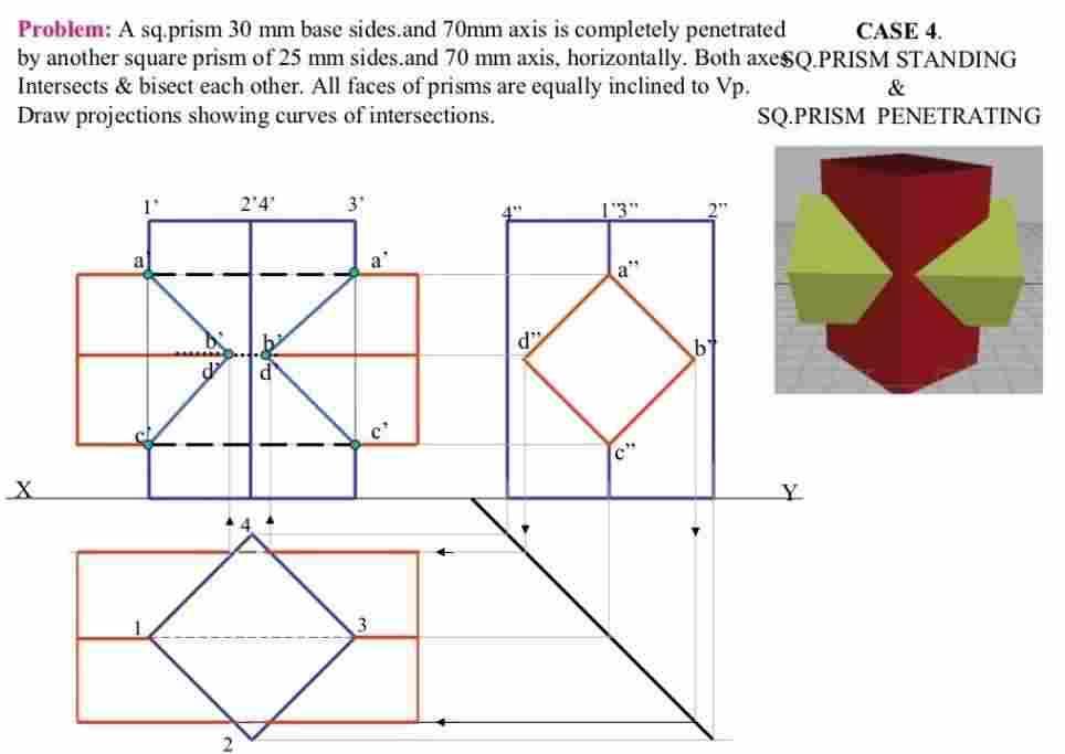
43 Questions: 1. A cylinder with a 60 base diameter and height 80 long is resting on its base on H.P. It is penetrated by another cylinder of 50 base diameter and height 90 long, such that their axes intersect each other at right angles. Draw the projections of the combination and show the curves of intersection. 2. A cylinder with a 60 base diameter and height 80 long is resting on its base on H.P. It is penetrated by another cylinder of 40 base diameter and height 90 long, the axis of which is parallel to both the principal planes. The two axes are 10 apart. Draw the projections of the combination and show the curves of intersection. 3. A cylinder with 60 base diameter and 80 long axis is resting on its base on H.P. It is penetrated by another cylinder with 30 base diameter and 110 long axis. The axis of both the cylinders is parallel to V.P. and bisects each other at an angle of Draw the projections and show their curves of intersection. 4. A square prism with 50 side and 80 long axis is resting on its base on the H.P., such that the face of the prism equally inclined to V.P. It is penetrated by cylinder of 40 base diameter and 90 long axis. The axes of prism and cylinder are 5 apart. Draw the projections of the combination and show the curves of intersection. 5. A cone of base 80 meter and 100 long axis is resting on its base on the H.P. It is completely penetrated by a cylinder with a 40 base meter. The axes of the solids interest each other at right angles, 30 above the base of the cone. Draw the projections of the combination and show COI. Page 43 of 56
44 Unit V: Isometric Projections: Principles of Isometric Projection Isometric Scale Isometric Views Conventions Isometric Views of Lines, Plane Figures, Simple and Compound Solids Isometric Projection of objects having non- isometric lines. Isometric Projection of Spherical Parts. Conversion of Isometric Views to Orthographic Views and Vice-versa Conventions Introduction to CAD: (For Internal Evaluation Weightage only): Introduction to CAD Software Package Commands.- Free Hand Sketches of 2D- Creation of 2D Sketches by CAD Package. Isometric Projections: Important Points / Definitions: When a solid is resting in its simple position, the front or top view, taken separately, gives an incomplete idea of the form of the object. When the solid is tilted from its simple position such that its axis is inclined to both H.P and V.P, the front view or the top view or sometimes both, give an air idea of the pictorial form of the object, i.e., all the surfaces are visualized in a single orthographic view. Iso means equal and metric projection means a projection to a reduced measure. An isometric projection is one type of pictorial projection in which the three dimensions of a solid are not only shown in one view, but also their dimension can be scaled from this drawing It is seen that all the edges and faces of the rectangular prism are equally inclined to the plane of all the edges and faces of the cube are equally inclined to the plane of projection. Hence the rectangular faces are seen as similar and equal rhombuses. The three lines AB, AD and AE are meeting at A. These edges are mutually perpendicular to each other in the solid. Since all these edges are equally inclined to H.P, they are making and angle of 120 o with each other in the plane of projection; also they are equally foreshortened. This leads us to the problem of selecting an isometric scale. Page 44 of 56
45 Isometric Axes: The lines AB, AD and AE meeting at a point A and making an angle of 120 o with each other are termed "isometric axes". Isometric Lines: The lines parallel to the isometric axes are termed isometric lines. The lines CD, CB etc are examples of isometric lines. Non-isometric Lines: The lines which are not parallel to isometric axes are termed non-isometric lines. The BD is an example. Isometric Planes: The planes representing the faces of the rectangular prism as well as other planes parallel to these planes are termed isometric planes. Isometric scale: Isometric projection is drawn using isometric scale, which converts true lengths into isometric lengths (foreshortened). Construction of isometric scale: Draw a horizontal line AB,From A draw a line AC at 45 o to represent actual or true length and another line AD at 30 o to AB to measure isometric length.,on AC mark the point 0, 1, 2 etc to represent actual lengths. From these points draw verticals to meet AD at 0, 1, 2 etc. The length A1 represents the isometric scale length of A1 and so on Difference between isometric view and isometric projection Isometric View Isometric Projection Drawn to actual scale Drawn to isometric scale When lines are drawn parallel to isometric When lines are drawn parallel to isometric axes, the axes, the true lengths are laid off. lengths are foreshortened to 0.81 time the actual lengths. Page 45 of 56
46 Problem: Draw the isometric projection of a rectangular prism of base 50 mm 10 mm and height 75 mm, when it rests with its base on H.P and one rectangular face is parallel to V.P. BOX METHOD: The isometric projection of solids like cube, square and rectangular prisms are drawn directly when their edges are parallel to the three isometric axes. The isometric projection of all other types of prisms and cylinders are drawn by enclosing them in a rectangular box. This method is called Box method. Example 1: Draw an isometric of a Pentagonal prism of base 1.5 and length 2.5 resting on one of its rectangular faces on H.P Page 46 of 56

47 ISOMETRIC VIEW OF A REGULAR HEXAGONAL PRISM (Resting on one of its rectangular faces on H.P) FOUR CENTERED METHOD: Example 2: Draw an isometric of a cylinder of base 1 and height 3 lyingon V.P Drawing Procedure 1. Join P with B and C which are the mid-points of the opposite sides of the rhombus. Similarly join R with A and D. 2. With P as centre and PC as radius draw an arc CB. Similarly with R as centre and RA as radius draw an arc AD 3. The lines PC and RD intersect at O1. With O1 as centre and O1D as radius draw an arc DC.Similarly with O2 (intersection of RA and PB) as centre and O2B as radius draw an arc BA. Thus complete the ellipse. 4. Refer step 1-3 in the Offset method and complete the isometric view of the cylinder. 3. Draw the Top view, Front view, Right view, Left view and Back view for the following isometric view. Page 47 of 56
48 Questions: 1) Draw an isometric view of a pentagonal prism having a base with 30 mm side and 60 mm long axis, resting on its base in H.P. with a face parallel and nearer to the V.P. 2) Draw an isometric projection of the hexagonal pyramid of base 30mm and axis height of 75mm long has its base is on H.P. and one of its base edge is parallel to the V.P. (ii) and also draw when its axis is parallel to H.P. and its base is parallel VP., the apex of the pyramid is closer than its base from V.P. 3) Draw an isometric projection of a frustum of the pentagonal pyramid with a 40 mm base side, 20mm top side, and 35mm height resting on its base in the H.P. 4) A hexagonal prism having base with a 30 mm side and a 70 mm long axis is resting on its base on the H.P. with a side of base parallel to the V.P. It is cut by an A.I.P. making 45 0 with the H.P. and bisecting the axis. Draw its isometric projection. 5) A cube with a 60 mm side has square holes of 30 mm side, cut through from all the six faces. The sides of the square holes are parallel to the edges of the cube. Draw the isometric view of the cube. Introduction to Auto CAD Important Points / Definitions: The term CAD (Computer Aided Drafting) applies to a wide range of programs that allow the user to create drawings, plans, and designs electronically. AutoCAD is one such program and its main claim to fame is that it is relatively easy to use, it is very comprehensive in its ability to create 2D and some 3D drawings, and it is very popular. Seventy percent of the CAD users in the world use AutoCAD. Applications of Computer aided drafting Mechanical: Design of machine elements, CNC machine tools, Robotics. Automotive: Kinematics, Hydraulics, Steering. Electrical: Circuit layout, Panel design, control system. Electronics: Schematic diagrams of PCs, Ics, etc. Communication: Communication network, satellite transmitting pictures, T.V Telecasting Civil: Mapping, contour plotting, building drawing, structural design. Architectural: Town planning, interior decorations, multi storied complex. Aerospace: Design of spacecraft, flight simulator, lofting Why with Auto CAD Current industrial practice (traditional drafting is obsolete). Helps students to explore other solid modelling softwares in their own disciplines Helps Mechanical students to generate 2-D Machine drawings as well as 3-D models using Pro-Engineers Page 48 of 56
49 AutoCAD Basics Tutorial Handout Drawing: When drawing in AutoCAD, you can type the command, into the command line at the bottom of the screen, or click on the toolbar icons. Next to each function is the shortcut, in parentheses) you can type to make drawing more efficient. POINT (po) draws a point at anywhere you specify by clicking on the location or by typing in the x-coordinate, tab, typing in the y-coordinate. Line (l) draws a line from one point to another. Same as above. Polyline (pl) draws a line/curve with multiple control points. If you hit Esc while drawing a polyline, the line is terminated from the last point you clicked or entered. If you type cl while drawing a polyline, it draws a line segment from your last clicked point to the starting point (closing the shape that you were drawing). If you type a while drawing a polyline, it allows you to draw an arc that are tangent to the last segment or arc. Notice that the arc only needs two points (starting and ending) point for the arc. If you type s while drawing an arc segment, you can draw an arc that is specified Rectangle draws a rectangle with two corners specified. Click to designate first corner of the rectangle. Click again to designate the opposite corner of the rectangle Polygon (pol) draws a polygon by the number of sides Enter in the number of sides Choose the center of the polygon If you choose inscribed in circle, it will draw the polygon inside a circle with your given radius. If you choose circumscribed in circle, it will draw the polygon with a circle inside of that polygon with your given radius. Circle (c) draws a circle centered at a point Click to pick the center of the circle Pick the radius length by entering it in or clicking how large the circle should be. If you type d after picking the center, you can enter in the diameter rather than the radius Page 49 of 56


50 Object Snap & Tracking: Settings that allow you to more specifically create your points, lines and polygons. : At the bottom of the screen, under the command line, there are some icons that allow you to turn on /off options listed below. AutoCAD Help: If you ever need help with a command, type in HELP. A window will pop up and you can type in the name of the command you need help with: line, circle, arc, etc. Page 50 of 56
51 Hatch (h) adds hatch patterns or fills to an enclosed area or to selected objects. BVRIT HYDERABAD As you scroll over enclosed areas, AutoCAD will display a preview of the hatch within that enclosed area, given your settings. After clicking hatch, type t to get the settings, as shown to the right. Click the for the Pattern option allows you to choose predefined hatches (shown below) You can adjust the angle and scale of the pattern. For the boundaries option: o When hatching a space defined by more than one object that causes overlapping zones, select Add Pick points. o When hatching a complete object, like a circle, rectangle, or polygon, select Add select object. Once the selections are set, you can click preview in the button on the left. Then ClickOk. Divide (div) divides a selected object into certain length or perimeter segment. You can draw from the node or you can place objects along the nodes (place trees 20 feet from each other on a sidewalk down a street). Select the object to divide, Enter the number of segments Modify: Erase (e): erases the selected objects. You can get the same effect by selecting objects and hitting Delete. Copy (cp): copies the selected objects from one place to another Select the object(s) Click or enter in the coordinates for your base point. Choose the second point, which will be where you want the copied object to go Move (m): moves your selected objects from one place to another Select the object(s) Choose your base point. Choose the point to move it to. Mirror (mi): mirrors objects along the line that you define. Select your object(s). Hit enter when all of them are selected Pick your first point, and then pick the end point of the mirror line. (Notice the mirrored object shows up as a preview while you draw the line. It will prompt you to erase the original object. Type y for yes or n for no. Page 51 of 56
52 Offset (o): offsets objects to the distance of your choice It will prompt you for a distance to offset first. Enter in that number or click two points on the screen giving the distance that you want. Pick the object that you want to offset and then choose the side you want to offset it. If you re offsetting the object(s) multiple times at the same distance, you can click on the new object that was offset and click on the side you want to continue offsetting it to. Scale (sc): scales objects by a given ratio Select the objects Click or enter in the base point Click or enter in the scale numerically Explode (x): break selected complex objects such as blocks and polylines down to lines and arcs. Select the blocks or polylines you want to explode. Hit esc to finish. Select objects to ensure they were successfully broken down. You should multiple end points for lines and arcs if successful. Trim (tr): trim objects using specified objects Using the following image as an example, select the object you want to use as the trimmer. For example, in this case, if you want to cut the circle and make it into an arc, you select the line first. And hit enter. Then choose the side you want to trim of the object you will be trimming. So for the example, if I want the arc to be the larger side of the circle, I would select the right side of the line, deleting the smaller side of the circle. Notice that it will trim the object immediately. Extend (ex): extend objects to reach specified objects Using the images below, select the object that you want to extend to. In this case, if you wanted to extend the line to the north end of the circle, you would select the circle first. Then hit enter. Page 52 of 56

53 Then choose the object you want to extend, which in this case would be the line itself. The line will extend immediately. Break (br): makes cuts through continuous lines. Select the object by choosing where you want the break to start and then click where you want the break to end. Keep in mind that if you re breaking a non-close shape, the break occurs between the two points (i.e. a line). If it s a closed shape, the portion that will be kept is going to be the portion between the points moving counterclockwise as shown below. Fillet (fillet): connects two objects with an arc that is tangent to the objects and has a specified radius. Select or type in fillet Type r for radius and enter in your radius (i.e. 0.5) Select the first object and then select the second object You can fillet: rectangles, tangential lines, arcs, etc. If the radius is 0, or you didn t enter in a number for the radius prior, fillet will just connect the two lines together (extends the lines so they join together).layers Page 53 of 56
54 In AutoCAD, layers are used to help give structure to your drawing. They are stacks of transparent overlays (or planes) located on the same coordinate system. It allows you to organize your drawings in a clearer manner. Turn off layer of a selected object,lock/unlock layer of a selected object Turn visibility on and off,each layer can be represented with different data, color. The default layer is 0 which cannot be deleted. Layer Properties include: Name Unique name for each layer (Be Descriptive) Color Color of the layer Linetype Continuous line, dashed line, dotted line, etc. Lineweight How thick or thin the line is On [Visibility] Makes the layer visible or not visible (If light bulb is yellow, it s on. If it s dark, it s off) Freeze Freezes the layer, doesn t allow you to see it Lock locks the layer from being selected but it is still visible (although more transparent then other layers) Difference between Visibility vs. Freeze is that frozen layers aren t included in regeneration, while layers with visibility off are. Dimensions Under Annotate, you can choose dimensions and leaders to makes notes on your drawings. Dimensions are simply the dimensions of the object (be it length, radius, etc.). Leaders are ways to make annotations in a drawing for a variety of reasons (manufacturing notes, detail bubbles, etc.). Page 54 of 56


55 Blocks Block: group of objects joined together as one entity. Type b for block. A block definition window will pop up, as shown below. Enter in a name (be descriptive) Click on Select Objects Make sure Convert to block is checked Select Pick point to choose a base point Click OK. You can now import the block as one entity. Page 55 of 56

56 View Zoom (z) Three ways to zoom in and out The middle wheel on the mouse allows you to zoom in and out (towards the computer monitor to zoom in, away to zoom out). Type z in the command line and choose from options. o All - use if you get lost o Extents zooms to the point where you can see all the objects drawn o Window allows you to select a window to zoom into that you specify o Previous takes you to the last view you saw View/Extents Pan (p) allows you to slide the drawing screen without changing the size. You can also pan by clicking on the wheel of the mouse and holding it down while you slide the mouse. Regen (re) regenerates the display, smoothing it out after zooming in or out and updates the screen, essentially a refresh button. Plot (or Print) To plot or print your drawing, the first thing you will want to do is switch Paper Space by clicking the Layout tab at the bottom of the screen. You will notice that the background should go from black to white. The dotted line, shown on the next page, represents the area that will be printed. Anything on the outside of that box will not show up on your paper. The inside box is your viewport. This shows you what will be printed out from your workspace, which you can adjust by zooming in and out or panning. To do so, make sure you double click on that box. If this is done correctly, you ll notice that the paper doesn t zoom in and out but everything inside the viewport will. Adjust the viewport window to eliminate as much white space as you can. Also, you will usually print out a drawing with a title block which you will need to insert into your layout before printing and which will take up some space on the paper. Page 56 of 56
DELHI TECHNOLOGICAL UNIVERSITY ENGINEERING GRAPHICS LAB MANUAL
 DELHI TECHNOLOGICAL UNIVERSITY ENGINEERING GRAPHICS LAB MANUAL NAME: - ROLL NO: - GROUP: - BRANCH: - GROUP TEACHER: Page 1 www.rooplalrana.com 1 GENERAL INSTRUCTIONS FOR ENGG. GRAPHICS LAB 1) Students
SIDDHARTH GROUP OF INSTITUTIONS :: PUTTUR
 SIDDHARTH GROUP OF INSTITUTIONS :: PUTTUR Siddharth Nagar, Narayanavanam Road 517583 QUESTION BANK Subject Code : Engineering Graphics& Design Course & Branch : B.Tech ALL Year & Sem : I B.Tech & I Sem
INSTITUTE OF AERONAUTICAL ENGINEERING
 Course Name Course Code Class Branch INSTITUTE OF AERONAUTICAL ENGINEERING Dundigal, Hyderabad - 500 043 MECHANICAL ENGINEERING TUTORIAL QUESTION BANK : ENGINEERING DRAWING : A10301 : I - B. Tech : Common
6. Draw the isometric view of a cone 40 mm diameter and axis 55 mm long when its axis is horizontal. Draw isometric scale. [16]
![6. Draw the isometric view of a cone 40 mm diameter and axis 55 mm long when its axis is horizontal. Draw isometric scale. [16]](/thumbs/85/92603403.jpg "6. Draw the isometric view of a cone 40 mm diameter and axis 55 mm long when its axis is horizontal. Draw isometric scale. [16]") Code No: R05010107 Set No. 1 I B.Tech Supplimentary Examinations, Aug/Sep 2007 ENGINEERING GRAPHICS ( Common to Civil Engineering, Mechanical Engineering, Mechatronics, Metallurgy & Material Technology,
Code No: R05010107 Set No. 1 I B.Tech Supplimentary Examinations, Aug/Sep 2007 ENGINEERING GRAPHICS ( Common to Civil Engineering, Mechanical Engineering, Mechatronics, Metallurgy & Material Technology,
ENGINEERING GRAPHICS (Engineering Drawing is the language of Engineers)
") ENGINEERING GRAPHICS (Engineering Drawing is the language of Engineers) UNIT 1 Conic Section (Ellipse, Parabola & Hyperbola) - Cycloids, epicycloids, hypocycloids & Involutes around circle and square scales
ENGINEERING GRAPHICS (Engineering Drawing is the language of Engineers) UNIT 1 Conic Section (Ellipse, Parabola & Hyperbola) - Cycloids, epicycloids, hypocycloids & Involutes around circle and square scales
GE ENGINEERING GRAPHICS
 ANNA UNIVERSITY, CHENNAI (REGULATION GE8152 - ENGINEERING GRAPHICS B.E SEMESTER I Lecture Tutorial Practical Marks Credits Total Hours 2 0 3 100 4 90 Mr.S.Gokul (Asst. Prof/Mech) Sri Eshwar College of
Drawing sheet: - The various size of the drawing sheet used for engineering drawing as per IS Are listed in the table
 Dronacharya Group of Institutions, Greater Noida Computer Aided Engineering Graphics (CAEG) (NCE 151/251) List of Drawing Sheets: 1. Letter writing & Dimensioning. 2. Projection of Points & Lines. 3. Projection
Engineering Graphics. Practical Book. Government Engineering College Bhuj (Kutch - Gujarat) Department of Mechanical Engineering
 Department of Mechanical Engineering") Engineering Graphics Practical Book ASHISH J. MODI Department of Mechanical Engineering Government Engineering College Bhuj 370 001 (Kutch - Gujarat) SYLLABUS (AS PER GUJARAT TECHNOLOGICAL UNIVERSITY,
Engineering Graphics Practical Book ASHISH J. MODI Department of Mechanical Engineering Government Engineering College Bhuj 370 001 (Kutch - Gujarat) SYLLABUS (AS PER GUJARAT TECHNOLOGICAL UNIVERSITY,
Second Semester Session Shri Ramdeobaba College of Engineering & Management, Nagpur. Department of Mechanical Engineering
 Second Semester Session- 2017-18 Shri Ramdeobaba College of Engineering & Management, Nagpur. Department of Mechanical Engineering Engineering Drawing Practical Problem Sheet Sheet No.:- 1. Scales and
4. Draw the development of the lateral surface of the part P of the cylinder whose front view is shown in figure 4. All dimensions are in cm.
 Code No: Z0122 / R07 Set No. 1 I B.Tech - Regular Examinations, June 2009 ENGINEERING GRAPHICS ( Common to Civil Engineering, Mechanical Engineering, Chemical Engineering, Bio-Medical Engineering, Mechatronics,
ENGINEERING DRAWING. 1. Set squares are used to draw different angles. What is the angel a formed by the 45⁰ set square? Give a brief answer.
 ENGINEERING DRAWING 1. Set squares are used to draw different angles. What is the angel a formed by the 45⁰ set square? Give a brief answer. 2. Which is the correct method of hatching a plane surface?
ENGINEERING DRAWING
 Subject Code: R13109/R13 Set No - 1 I B. Tech I Semester Regular/Supplementary Examinations Jan./Feb. - 2015 ENGINEERING DRAWING (Common to ECE, EIE, Bio-Tech, EComE, Agri.E) Time: 3 hours Max. Marks:
Set No - 1 I B. Tech I Semester Regular/Supplementary Examinations Jan./Feb ENGINEERING DRAWING (EEE)
") Set No - 1 I B. Tech I Semester Regular/Supplementary Examinations Jan./Feb. - 2015 ENGINEERING DRAWING Time: 3 hours (EEE) Question Paper Consists of Part-A and Part-B Answering the question in Part-A
Set No - 1 I B. Tech I Semester Regular/Supplementary Examinations Jan./Feb. - 2015 ENGINEERING DRAWING Time: 3 hours (EEE) Question Paper Consists of Part-A and Part-B Answering the question in Part-A
Chapter 4 ORTHOGRAPHIC PROJECTION
 Chapter 4 ORTHOGRAPHIC PROJECTION 4.1 INTRODUCTION We, the human beings are gifted with power to think. The thoughts are to be shared. You will appreciate that different ways and means are available to
M.V.S.R. ENGINEERING COLLEGE, NADERGUL HYDERABAD B.E. I/IV I - Internal Examinations (November 2014)
") Sub: Engineering Graphics Branches: Civil (1&2), IT-2 Time: 1 Hr 15 Mins Max. Marks: 40 Note: Answer All questions from Part-A and any Two from Part B. Assume any missing data suitably. 1. Mention any
Sub: Engineering Graphics Branches: Civil (1&2), IT-2 Time: 1 Hr 15 Mins Max. Marks: 40 Note: Answer All questions from Part-A and any Two from Part B. Assume any missing data suitably. 1. Mention any
Chapter 5 SECTIONS OF SOLIDS 5.1 INTRODUCTION
 Chapter 5 SECTIONS OF SOLIDS 5.1 INTRODUCTION We have studied about the orthographic projections in which a 3 dimensional object is detailed in 2-dimension. These objects are simple. In engineering most
B.E. 1 st Year Engineering Graphics ( )
") B.E. 1 st Year Engineering Graphics (2110013) Department of Mechanical Engineering Darshan Institute of Engg. & Tech., Rajkot Darshan Institute Of Engg. & Technology List Of Instruments SR NO. 1. Set-Square
B.E. 1 st Year Engineering Graphics (2110013) Department of Mechanical Engineering Darshan Institute of Engg. & Tech., Rajkot Darshan Institute Of Engg. & Technology List Of Instruments SR NO. 1. Set-Square
BHARATHIDASAN ENGINEERING COLLEGE MGR NAGAR, NATRAM PALLI. Department of Mechanical Engineering GE6152 ENGINEERING GRAPHICS NOTES
 BHARATHIDASAN ENGINEERING COLLEGE MGR NAGAR, NATRAM PALLI Department of Mechanical Engineering GE6152 ENGINEERING GRAPHICS NOTES GE6152 ENGINEERING GRAPHICS OBJECTIVES: concepts, ideas and design of Engineering
APJ ABDUL KALAM TECHNOLOGICAL UNIVERSITY SECOND SEMESTER B.TECH DEGREE EXAMINATION, MAY PART A Answer ANY Two questions. 10 marks each.
 B B2B111 Pages: 2 Reg. No. Name: SECOND SEMESTER B.TECH DEGREE EXAMINATION, MAY 2017 Max.Marks:50 Course Code: BE110 Duration:3Hours Answer ANY Two questions. 10 marks each. 1. A line AB 100 mm long and
NOTE: Topic No. 1, 8 and 9 of the above syllabus to be covered in Practical Hours.
 Subject Engineering Graphics Teaching scheme Theory Tutorial Practical Credits 2 0 4 6 Engineering Graphics syllabus 1. Introduction to Engineering Graphics, Drawing instruments and accessories, BIS SP
UNIT I PLANE CURVES AND FREE HAND SKETCHING CONIC SECTIONS
 UNIT I PLANE CURVES AND FREE HAND SKETCHING CONIC SECTIONS Definition: The sections obtained by the intersection of a right circular cone by a cutting plane in different positions are called conic sections
ISOMETRIC PROJECTION. Contents. Isometric Scale. Construction of Isometric Scale. Methods to draw isometric projections/isometric views
 ISOMETRIC PROJECTION Contents Introduction Principle of Isometric Projection Isometric Scale Construction of Isometric Scale Isometric View (Isometric Drawings) Methods to draw isometric projections/isometric
Unit-5 ISOMETRIC PROJECTION
 Unit-5 ISOMETRIC PROJECTION Importance Points in Isometric: 1. For drawing the isometric, the object must be viewed such that either the front -right or the left edges becomes nearest. 2. All vertical
SIMILARLY IN CASE OF TINY OBJECTS DIMENSIONS MUST BE INCREASED FOR ABOVE PURPOSE. HENCE THIS SCALE IS CALLED ENLARGING SCALE. FOR FULL SIZE SCALE R.
 DIMENSIONS OF LARGE OBJECTS MUST BE REDUCED TO ACCOMMODATE ON STANDARD SIZE DRAWING SHEET.THIS REDUCTION CREATES A SCALE OF THAT REDUCTION RATIO, WHICH IS GENERALLY A FRACTION.. SUCH A SCALE IS CALLED
ENGINEERING DRAWING. UNIT III - Part A
 DEVELOPMENT OF SURFACES: ENGINEERING DRAWING UNIT III - Part A 1. What is meant by development of surfaces? 2. Development of surfaces of an object is also known as flat pattern of the object. (True/ False)
GE 6152 ENGINEERING GRAPHICS
 GE 6152 ENGINEERING GRAPHICS UNIT - 4 DEVELOPMENT OF SURFACES Development of lateral surfaces of simple and truncated solids prisms, pyramids, cylinders and cones - Development of lateral surfaces of solids
ENGINEERING GRAPHICS UNIT V ISOMETRIC PROJECTION PERSPECTIVE PROJECTION
 ENGINEERING GRAPHICS UNIT V ISOMETRIC PROJECTION PERSPECTIVE PROJECTION 1.PICTORIAL PROJECTIONS To visualize the shape of the whole object in its 3- D form, all the two or three orthographic views of the
GOVERNMENT POLYTECHNIC, VALSAD MECHANICAL ENGINEERING DEPARTMENT ASSIGNMENT SUB: MECHANICAL DRAFTING (C321901) TERM:172
 TERM:172") GOVERNMENT POLYTECHNIC, VALSAD MECHANICAL ENGINEERING DEPARTMENT ASSIGNMENT SUB: MECHANICAL DRAFTING (C321901) TERM:172 1) When all the dimension are placed above the dimension line, it is called (a) Aligned
GOVERNMENT POLYTECHNIC, VALSAD MECHANICAL ENGINEERING DEPARTMENT ASSIGNMENT SUB: MECHANICAL DRAFTING (C321901) TERM:172 1) When all the dimension are placed above the dimension line, it is called (a) Aligned
ENGINEERING DRAWING I Semester (AE/ ME/ CE) IA-R16
 IA-R16") INSTITUTE OF AERONAUTICAL ENGINEERING (Autonomous) Dundigal, Hyderabad -500 043 MECHANICAL ENGINEERING ENGINEERING DRAWING I Semester (AE/ ME/ CE) IA-R16 Prepared By Prof B.V.S. N. Rao, Professor, Mr.
INSTITUTE OF AERONAUTICAL ENGINEERING (Autonomous) Dundigal, Hyderabad -500 043 MECHANICAL ENGINEERING ENGINEERING DRAWING I Semester (AE/ ME/ CE) IA-R16 Prepared By Prof B.V.S. N. Rao, Professor, Mr.
ORDINARY LEVEL PAST PAPERS
 ORDINARY LEVEL PAST PAPERS UNEB S4 1982 SECTION I PLANE GEOMETRY 1. (a) Construct a diagonal scale of 40mm to 10mm to read up to 20mm by 0.02mm. (b) Indicate on your scale the following readings. (i) 14.8mm.
Multi-View Drawing Review
 Multi-View Drawing Review Sacramento City College EDT 300/ENGR 306 EDT 300 / ENGR 306 - Chapter 5 1 Objectives Identify and select the various views of an object. Determine the number of views needed to
B.E. 1 st year ENGINEERING GRAPHICS
 B.E. 1 st year ENGINEERING GRAPHICS Introduction 1. What is an Engineering Graphics and its requirements? A standardized graphic representation of physical objects and their relationship is called Engineering
Change of position method:-
 Projections of Planes PROJECTIONS OF PLANES A plane is a two dimensional object having length and breadth only. Thickness is negligible. Types of planes 1. Perpendicular plane which have their surface
ENGINEERING CURVES (Week -2)
") UNIT 1(a) CONIC SECTIONS ENGINEERING CURVES (Week -2) These are non-circular curves drawn by free hand. Sufficient number of points are first located and then a smooth curve passing through them are drawn
UNIT 1(a) CONIC SECTIONS ENGINEERING CURVES (Week -2) These are non-circular curves drawn by free hand. Sufficient number of points are first located and then a smooth curve passing through them are drawn
ENGINEERING GRAPHICS
 ENGINEERING GRAPHICS Course Structure Units Topics Marks Unit I Plane Geometry 16 1 Lines, angles and rectilinear figures 2 Circles and tangents 3 Special curves: ellipse, parabola, involute, cycloid.
B.E. I & II SEM ENGINEERING GRAPHICS
 B.E. I & II SEM ENGINEERING GRAPHICS UNIT -I Drawing: The way of conveying the ideas through the systematic lines on the paper. The art of representation of an object by systematic lines on a paper. Classification:
ENGINEERING DRAWING I
 INSTITUTE OF ENGINEERING DEPARTMENT OF MECHANICAL ENGINEERING ENGINEERING DRAWING I [TUTORIAL SHEETS] 1 CONTENTS Sheet No. 1: Technical Lettering 3 Sheet No. 2: Plane Geometrical Construction 5 Sheet No.
Solutions to Exercise problems
 Brief Overview on Projections of Planes: Solutions to Exercise problems By now, all of us must be aware that a plane is any D figure having an enclosed surface area. In our subject point of view, any closed
Copyrighted Material. Copyrighted Material. Copyrighted. Copyrighted. Material
 Engineering Graphics ORTHOGRAPHIC PROJECTION People who work with drawings develop the ability to look at lines on paper or on a computer screen and "see" the shapes of the objects the lines represent.
Technical Drawing Paper 1 - Higher Level (Plane and Solid Geometry)
") Coimisiún na Scrúduithe Stáit State Examinations Commission 2008. M81 Leaving Certificate Examination 2008 Technical Drawing Paper 1 - Higher Level (Plane and Solid Geometry) (200 Marks) Friday 13 June
Coimisiún na Scrúduithe Stáit State Examinations Commission 2008. M81 Leaving Certificate Examination 2008 Technical Drawing Paper 1 - Higher Level (Plane and Solid Geometry) (200 Marks) Friday 13 June
Scales. 1. Basic Information. 2. Types and important units. 3. Plain Scales (3 Problems) 4. Diagonal Scales - information
 4. Diagonal Scales - information") Contents 1. Scales 2. Engineering Curves - I 3. Engineering Curves - II 4. Loci of Points 5. Orthographic Projections - Basics 6. Conversion of Pictorial View into Orthographic Views 7. Projections of
Contents 1. Scales 2. Engineering Curves - I 3. Engineering Curves - II 4. Loci of Points 5. Orthographic Projections - Basics 6. Conversion of Pictorial View into Orthographic Views 7. Projections of
UNIT 5a STANDARD ORTHOGRAPHIC VIEW DRAWINGS
 UNIT 5a STANDARD ORTHOGRAPHIC VIEW DRAWINGS 5.1 Introduction Orthographic views are 2D images of a 3D object obtained by viewing it from different orthogonal directions. Six principal views are possible
ORTHOGRAPHIC PROJECTION
 ORTHOGRAPHIC PROJECTION INTRODUCTION Any object has three dimensions, that is, length, width and thickness. A projection is defined as a representation of an object on a two dimensional plane. The projections
Trade of Metal Fabrication. Module 6: Fabrication Drawing Unit 13: Parallel Line Development Phase 2
 Trade of Metal Fabrication Module 6: Fabrication Drawing Unit 13: Parallel Line Development Phase 2 Table of Contents List of Figures... 4 List of Tables... 5 Document Release History... 6 Module 6 Fabrication
 RAKESH JALLA B.Tech. (ME), M.Tech. (CAD/CAM) Assistant Professor, Department Of Mechanical Engineering, CMR Institute of Technology. CONICS Curves Definition: It is defined as the locus of point P moving
Design & Communication Graphics
 L.84/85 Design & Communication Graphics Marking Scheme Ordinary Pg. 3 Higher Pg. 12 2013 L.84/85_MS 1/20 2013 L.84/85_MS 2/20 SECTION A - Core - Answer Any Three of the questions on this A3 sheet A-1.
3. The dimensioning SYMBOLS for arcs and circles should be given:
 Draft Student Name: Teacher: District: Date: Wake County Test: 9_12 T and I IC61 - Drafting I Test 2 Description: 4.08 Dimensioning Form: 501 1. The MINIMUM amount of space between two, ADJACENT DIMENSION
LECTURE NOTES skyupsmedia HYDRAULIC MACHINES II B. Tech I semester (JNTUH-R13) I B.TECH. JNTU (R16)
 I B.TECH. JNTU (R16)") LECTURE NOTES ON MECHANICS ENGINEERING OF FLUIDS DRAWING AND HDRAULIC MACHINES II B. Tech I semester (JNTUH-R13) I B.TECH. JNTU (R16) s ENGINEERING DRAWING I Semester: AE / CE / ME Course Code Category
LECTURE NOTES ON MECHANICS ENGINEERING OF FLUIDS DRAWING AND HDRAULIC MACHINES II B. Tech I semester (JNTUH-R13) I B.TECH. JNTU (R16) s ENGINEERING DRAWING I Semester: AE / CE / ME Course Code Category
Multiviews and Auxiliary Views
 Multiviews and Auxiliary Views Multiviews and Auxiliary Views Objectives Explain orthographic and multiview projection. Identifying the six principal views. Apply standard line practices to multiviews
I B.TECH- I SEMESTER DEPARTMENT OF MECHANICAL ENGINEERING ENGINEERING DRAWING
 I B.TECH- I SEMESTER DEPARTMENT OF MECHANICAL ENGINEERING ENGINEERING DRAWING ENGINEERING DRAWING UNIT-V DEFINITIONS: Axonometric Trimetric Dimetric Isometric It is a parallel technique used to create
Geometry 2001 part 1
 Geometry 2001 part 1 1. Point is the center of a circle with a radius of 20 inches. square is drawn with two vertices on the circle and a side containing. What is the area of the square in square inches?
ENGINEERING GRAPHICS
 ENGINEERING GRAPHICS CLASS - XII (046) DESIGN OF THE QUESTION PAPER Time : 3 Hrs Max. Marks : 70 The weightage of the distribution of marks over different contents of the question paper shall be as follows:
Course Title: ENGINEERING GRAPHICS-I Course Code: 15ME12D. Type of course: Lectures & Practice Total Contact Hours: 78
 Course Title: ENGINEERING GRAPHICS-I Course Code: 15ME12D Credits (L:T:P) : 0:2:4 Core/ Elective: Core Type of course: Lectures & Practice Total Contact Hours: 78 CIE- 25 Marks SEE 100 Marks (***(Common
Student Name: Teacher: Date: District: Rowan. Assessment: 9_12 T and I IC61 - Drafting I Test 2. Description: Drafting 1 - Test 6.
 Student Name: Teacher: Date: District: Rowan Assessment: 9_12 T and I IC61 - Drafting I Test 2 Description: Drafting 1 - Test 6 Form: 501 1. 2X on a hole note means: A. Double the size of the hole. B.
2. Line composed of closely and evenly spaced short dashes in a drawing represents
 1. Hidden lines are drawn as (a) dashed narrow lines (b) dashed wide lines (c) long-dashed dotted wide line (d) long-dashed double dotted wide line Ans: (a) 2. Line composed of closely and evenly spaced
Bridge Course On Engineering Drawing for Mechanical Engineers
 G. PULLAIAH COLLEGE OF ENGINEERING AND TECHNOLOGY Accredited by NAAC with A Grade of UGC, Approved by AICTE, New Delhi Permanently Affiliated to JNTUA, Ananthapuramu (Recognized by UGC under 2(f) and 12(B)
(As per New Revised Syllabus of Anna University) Department of Mechanical Engineering. SATHYABAMA UNIVERSITY Jeppiaar Nagar, Chennai
 Department of Mechanical Engineering. SATHYABAMA UNIVERSITY Jeppiaar Nagar, Chennai") (1*,1((5,1* *5$3+,&6 (As per New Revised Syllabus of Anna University) Dr. S.RAMACHANDRAN, M.E., Ph.D. Professor & Head K. PANDIAN, M.E., E.V.V.RAMANAMURTHY, M.Tech., R. DEVARAJ, M.E., Associate Professors
(1*,1((5,1* *5$3+,&6 (As per New Revised Syllabus of Anna University) Dr. S.RAMACHANDRAN, M.E., Ph.D. Professor & Head K. PANDIAN, M.E., E.V.V.RAMANAMURTHY, M.Tech., R. DEVARAJ, M.E., Associate Professors
Problem Set #4 Due 5/3 or 5/4 Pd
 Geometry Name Problem Set #4 Due 5/3 or 5/4 Pd Directions: To receive full credit, show all required work. Questions may have multiple correct answers. Clearly indicate the answers chosen. For multiple
Design & Communication Graphics Higher Level Section A (60 Marks)
") M.85A ªM.858 Leaving Certificate Examination, 2009 Design & Communication Graphics Higher Level Section A (60 Marks) Time: 3 Hours This examination is divided into three sections: SECTION A SECTION B SECTION
M.85A ªM.858 Leaving Certificate Examination, 2009 Design & Communication Graphics Higher Level Section A (60 Marks) Time: 3 Hours This examination is divided into three sections: SECTION A SECTION B SECTION
Understanding Projection Systems
 Understanding Projection Systems A Point: A point has no dimensions, a theoretical location that has neither length, width nor height. A point shows an exact location in space. It is important to understand
Whirlygigs for Sale! Rotating Two-Dimensional Figures through Space. LESSON 4.1 Skills Practice. Vocabulary. Problem Set
 LESSON.1 Skills Practice Name Date Whirlygigs for Sale! Rotating Two-Dimensional Figures through Space Vocabulary Describe the term in your own words. 1. disc Problem Set Write the name of the solid figure
DEPARTMENT OF MECHANICAL ENGINEERING, IIT DELHI
 MEL 110 LABORATORY 1 (to be done in CAGI Lab. Room: III 331) DURATION: 3 Hrs 50 Min. Note: Missing dimensions may be suitably assumed. Exercise 1: Visualize orthographic and isometric views of 3D models/objects:
Standards of Learning Guided Practice Suggestions. For use with the Mathematics Tools Practice in TestNav TM 8
 Standards of Learning Guided Practice Suggestions For use with the Mathematics Tools Practice in TestNav TM 8 Table of Contents Change Log... 2 Introduction to TestNav TM 8: MC/TEI Document... 3 Guided
Engineering Graphics, Class 8 Orthographic Projection. Mohammad I. Kilani. Mechanical Engineering Department University of Jordan
 Engineering Graphics, Class 8 Orthographic Projection Mohammad I. Kilani Mechanical Engineering Department University of Jordan Multi view drawings Multi view drawings provide accurate shape descriptions
Unit 4: Geometric Construction (Chapter4: Geometry For Modeling and Design)
") Unit 4: Geometric Construction (Chapter4: Geometry For Modeling and Design) DFTG-1305 Technical Drafting Instructor: Jimmy Nhan OBJECTIVES 1. Identify and specify basic geometric elements and primitive
Unit 4: Geometric Construction (Chapter4: Geometry For Modeling and Design) DFTG-1305 Technical Drafting Instructor: Jimmy Nhan OBJECTIVES 1. Identify and specify basic geometric elements and primitive
ENGINEERING GRAPHICS 1E9
 Lecture 3 Monday, 15 December 2014 1 ENGINEERING GRAPHICS 1E9 Lecture 3: Isometric Projections Lecture 3 Monday, 15 December 2014 2 What is ISOMETRIC? It is a method of producing pictorial view of an object
SAMPLE QUESTION PAPER III ENGINEERING GRAPHICS (046) Time Allowed: 3 hours Maximum Marks: 70
 Time Allowed: 3 hours Maximum Marks: 70") SAMPLE QUESTION PAPER III ENGINEERING GRAPHICS (046) Time Allowed: 3 hours Maximum Marks: 70 Note: (i) Attempt all the questions. (ii) Use both sides of the drawing sheet, if necessary. (iii) All dimensions
SAMPLE QUESTION PAPER III ENGINEERING GRAPHICS (046) Time Allowed: 3 hours Maximum Marks: 70 Note: (i) Attempt all the questions. (ii) Use both sides of the drawing sheet, if necessary. (iii) All dimensions
JUNIOR CERTIFICATE 2009 MARKING SCHEME TECHNICAL GRAPHICS HIGHER LEVEL
 . JUNIOR CERTIFICATE 2009 MARKING SCHEME TECHNICAL GRAPHICS HIGHER LEVEL Sections A and B Section A any ten questions from this section Q1 12 Four diagrams, 3 marks for each correct label. Q2 12 2 marks
1 st Subject: 2D Geometric Shape Construction and Division
 Joint Beginning and Intermediate Engineering Graphics 2 nd Week 1st Meeting Lecture Notes Instructor: Edward N. Locke Topic: Geometric Construction 1 st Subject: 2D Geometric Shape Construction and Division
Geometry For Technical Drawing Chapter 4
 Geometry For Technical Drawing Chapter 4 Sacramento City College EDT 300/ENGR 306 EDT 300/ENGR 306 1 Objectives Identify and describe geometric shapes and constructions used by drafters. Construct various
TPCT s College of Engineering, Osmanabad. Laboratory Manual. Engineering Graphics. For. First Year Students. Manual Prepared by B. G.
 TPCT s College of Engineering, Osmanabad Laboratory Manual Engineering Graphics For First Year Students Manual Prepared by B. G. Kadam Author COE, Osmanabad TPCT s College of Engineering Solapur Road,
MODELING AND DESIGN C H A P T E R F O U R
 MODELING AND DESIGN C H A P T E R F O U R OBJECTIVES 1. Identify and specify basic geometric elements and primitive shapes. 2. Select a 2D profile that best describes the shape of an object. 3. Identify
Period: Date Lesson 2: Common 3-Dimensional Shapes and Their Cross- Sections
 : Common 3-Dimensional Shapes and Their Cross- Sections Learning Target: I can understand the definitions of a general prism and a cylinder and the distinction between a cross-section and a slice. Warm
ENGINEERING DRAWING IM 09 AND GRAPHICAL COMMUNICATION
 IM SYLLABUS (2014) ENGINEERING DRAWING IM 09 AND GRAPHICAL COMMUNICATION SYLLABUS Engineering Drawing and Graphical Communication IM 09 (Available in September) Syllabus 1 Paper (3 hours) Aims The aims
Downloaded from
 Understanding Elementary Shapes 1 1.In the given figure, lines l and m are.. to each other. (A) perpendicular (B) parallel (C) intersect (D) None of them. 2.a) If a clock hand starts from 12 and stops
CE 100 Civil Engineering Drawing Sessional (Lab Manual)
") CE 100 Civil Engineering Drawing Sessional (Lab Manual) Department of Civil Engineering Ahsanullah University of Science and Technology November, 2017 1 Preface This course is designed to provide civil
CE 100 Civil Engineering Drawing Sessional (Lab Manual) Department of Civil Engineering Ahsanullah University of Science and Technology November, 2017 1 Preface This course is designed to provide civil
1 ISOMETRIC PROJECTION SECTION I: INTRODUCTION TO ISOMETRIC PROJECTION
 1 ISOMETRIC PROJECTION SECTION I: INTRODUCTION TO ISOMETRIC PROJECTION Orthographic projection shows drawings of an object in a two-dimensional format, with views given in plan, elevation and end elevation
Design & Communication Graphics Higher Level Sections B and C (180 marks)
") Coimisiún na Scrúduithe Stáit State Examinations Commission 2016. M81BC Leaving Certificate Examination, 2016 Design & Communication Graphics Higher Level Sections B and C (180 marks) Wednesday, 22 June
Coimisiún na Scrúduithe Stáit State Examinations Commission 2016. M81BC Leaving Certificate Examination, 2016 Design & Communication Graphics Higher Level Sections B and C (180 marks) Wednesday, 22 June
11/12/2015 CHAPTER 7. Axonometric Drawings (cont.) Axonometric Drawings (cont.) Isometric Projections (cont.) 1) Axonometric Drawings
 Axonometric Drawings (cont.) Isometric Projections (cont.) 1) Axonometric Drawings") CHAPTER 7 1) Axonometric Drawings 1) Introduction Isometric & Oblique Projection Axonometric projection is a parallel projection technique used to create a pictorial drawing of an object by rotating the
CHAPTER 7 1) Axonometric Drawings 1) Introduction Isometric & Oblique Projection Axonometric projection is a parallel projection technique used to create a pictorial drawing of an object by rotating the
ORTHOGRAPHIC PROJECTION
 ORTHOGRAPHIC PROJECTION C H A P T E R S I X OBJECTIVES 1. Recognize and the symbol for third-angle projection. 2. List the six principal views of projection. 3. Understand which views show depth in a drawing
Geometry. Practice Pack
 Geometry Practice Pack WALCH PUBLISHING Table of Contents Unit 1: Lines and Angles Practice 1.1 What Is Geometry?........................ 1 Practice 1.2 What Is Geometry?........................ 2 Practice
E GRAPHICS ISOMETRIC PROJECTIONS S.RAMANATHAN ASST PROF MVSREC PH: CONCEPTS.
 E GRPHIS ISOMETRI PROJETIONS S.RMNTHN SST PROF MVSRE ONEPTS. Isometric projections are 3-D representation of objects. Since we deal mostly with solids which are 3-D objects, we use isometric projections
ENGINEERING GRAPHICS (Code No. 046)
") ENGINEERING GRAPHICS (Code No. 046) CLASS XI-XII The subject of 'Engineering Graphics' has become an indispensable tool for Engineers, Technocrats, Architects, Draftsmen, Surveyors, Designers and many
ENGINEERING GRAPHICS (Code No. 046) CLASS XI-XII The subject of 'Engineering Graphics' has become an indispensable tool for Engineers, Technocrats, Architects, Draftsmen, Surveyors, Designers and many
David Anderson. Gill & Macmillan
 One Volume Edition David nderson 3 and 4 Online Worksheets Ideal as homework exercises Will save students time as the problems are already set up on the page Worksheets are referenced in the text The material
Engineering Graphics UNIVERSITY OF TEXAS RIO GRANDE VALLEY JAZMIN LEY HISTORY OF ENGINEERING GRAPHICS GEOMETRIC CONSTRUCTION & SOLID MODELING
 Engineering Graphics UNIVERSITY OF TEXAS RIO GRANDE VALLEY JAZMIN LEY HISTORY OF ENGINEERING GRAPHICS GEOMETRIC CONSTRUCTION & SOLID MODELING Overview History of Engineering Graphics: Sketching, Tools,
University of Houston High School Mathematics Contest Geometry Exam Spring 2016
 University of Houston High School Mathematics ontest Geometry Exam Spring 016 nswer the following. Note that diagrams may not be drawn to scale. 1. In the figure below, E, =, = 4 and E = 0. Find the length
ENGINEERING GRAPHICS (XI-XII) (Code No. 046)
 (Code No. 046)") ENGINEERING GRAPHICS (XI-XII) (Code No. 046) The subject of 'Engineering Graphics' has become an indispensable tool for Engineers, Technocrats, Architects, Draftsmen, Surveyors, Designers and many other
ENGINEERING GRAPHICS (XI-XII) (Code No. 046) The subject of 'Engineering Graphics' has become an indispensable tool for Engineers, Technocrats, Architects, Draftsmen, Surveyors, Designers and many other
SHOP MATHEMATICS CHAPTER 14. Hull Maintenance Technician NAVEDTRA DEPARTMENT OF THE NAVY. Prepared by: Garry A Pace PE
 SHOP MATHEMATICS CHAPTER 14 Hull Maintenance Technician NAVEDTRA 14119 DEPARTMENT OF THE NAVY Prepared by: Garry A Pace PE OCT 2015 1 Preface The intent of this document is to help potential welding inspectors
JK XY LJ LJ ZX KL KL YZ LJ KL YX KJ. Final Exam Review Modules 10 16, 18 19
 Geometry Final Exam Review Modules 10 16, 18 19 Use the following information for 1 3. The figure is symmetric about the x axis. Name: 6. In this figure ~. Which statement is not true? A JK XY LJ ZX C
TECHNICAL DRAWING APPLICATIONS (65)
") TECHNICAL DRAWING APPLICATIONS (65) Aims: 1. To develop competence among the students to pursue technical courses like Engineering, Architecture, Draftsmanship Surveying and other professional courses.
TECHNICAL DRAWING APPLICATIONS (65) Aims: 1. To develop competence among the students to pursue technical courses like Engineering, Architecture, Draftsmanship Surveying and other professional courses.
CHAPTER 01 PRESENTATION OF TECHNICAL DRAWING. Prepared by: Sio Sreymean
 CHAPTER 01 PRESENTATION OF TECHNICAL DRAWING Prepared by: Sio Sreymean 2015-2016 Why do we need to study this subject? Effectiveness of Graphics Language 1. Try to write a description of this object. 2.
Design & Communication Graphics Higher Level Section A (60 Marks)
") 1 L.85A Pre-Leaving Certificate Examination, 2011 Design & Communication Graphics Higher Level Section A (60 Marks) Time: 3 Hours This examination is divided into three sections: SECTION A SECTION B SECTION
1 L.85A Pre-Leaving Certificate Examination, 2011 Design & Communication Graphics Higher Level Section A (60 Marks) Time: 3 Hours This examination is divided into three sections: SECTION A SECTION B SECTION
ME 111: Engineering Drawing
 ME 111: Engineering Drawing Lecture 5 12-08-2011 Orthographic projection and Projection of Points Indian Institute of Technology Guwahati Guwahati 781039 1 Orthographic Projection A parallel projection
2. Here are some triangles. (a) Write down the letter of the triangle that is. right-angled, ... (ii) isosceles. ... (2)
 Write down the letter of the triangle that is. right-angled, ... (ii) isosceles. ... (2)") Topic 8 Shapes 2. Here are some triangles. A B C D F E G (a) Write down the letter of the triangle that is (i) right-angled,... (ii) isosceles.... (2) Two of the triangles are congruent. (b) Write down
Topic 8 Shapes 2. Here are some triangles. A B C D F E G (a) Write down the letter of the triangle that is (i) right-angled,... (ii) isosceles.... (2) Two of the triangles are congruent. (b) Write down
TIME SCHEDULE. Module Topic Periods 1 Importance of Engineering Graphics Drawing Instruments Drawing Standards Lettering and Numbering
 COURSE TITLE : ENGINEERING GRAPHICS (First Semester) COURSE CODE : COURSE CATEGORY : F PERIODS/WEEK : 3 PERIODS/SEMESTER : 54 CREDITS : Examination in the Second Semester RATIONALE: Engineering Graphics
Engineering Graphics. Class 2 Drafting Instruments Mohammad Kilani
 Engineering Graphics Class 2 Drafting Instruments Mohammad Kilani Drafting Instruments A Design is as good as its instruments A engineering drawing is a highly stylized graphic representation of an idea.
ENGINEERING DRAWING CLASS-XI THEORY
 CLASS-XI THEORY One Paper 3 Hours 7O Marks Unit Marks PLANE GEOMETRY 1. Construction of lines, angles and rectilner figures 4 2. Construction of circles, semi-circles and tangents 6 3. Construction of
Design & Communication Graphics Higher Level Section A (60 marks)
") Coimisiún na Scrúduithe Stáit State Examinations Commission 2011. M81A Leaving Certificate Examination, 2011 Design & Communication Graphics Higher Level Section A (60 marks) Friday, 17 June Afternoon,
Coimisiún na Scrúduithe Stáit State Examinations Commission 2011. M81A Leaving Certificate Examination, 2011 Design & Communication Graphics Higher Level Section A (60 marks) Friday, 17 June Afternoon,
Civil Engineering Drawing
 Civil Engineering Drawing Third Angle Projection In third angle projection, front view is always drawn at the bottom, top view just above the front view, and end view, is drawn on that side of the front
Student Name: Teacher: Date: District: Rowan. Assessment: 9_12 T and I IC61 - Drafting I Test 1. Description: Unit C - Sketching - Test 2.
 Student Name: Teacher: Date: District: Rowan Assessment: 9_12 T and I IC61 - Drafting I Test 1 Description: Unit C - Sketching - Test 2 Form: 501 1. The most often used combination of views includes the: