B.E. 1 st Year Engineering Graphics ( )
|
|
|
- Morgan Wells
- 5 years ago
- Views:
Transcription
 Department")

1 B.E. 1 st Year Engineering Graphics ( ) Department of Mechanical Engineering Darshan Institute of Engg. & Tech., Rajkot
2
 4. Engineering Compass 5. Sketch Book ( 3-20 page & 3-40 page) 6. Drawing Clip 7. Scale (1-foot) 8.")
3 Darshan Institute Of Engg. & Technology List Of Instruments SR NO. 1. Set-Square Pair INSTRUMENTS 2. Apsara Pencil (2H & 5H) 3. Eraser (Non-dust) 4. Engineering Compass 5. Sketch Book ( 3-20 page & 3-40 page) 6. Drawing Clip 7. Scale (1-foot) 8. Pro-Circle
4
5 INDEX Chapter. No. Chapter Name 1 Practice Work 2 Plane scale and diagonal scale 3 Engineering curves 4 Projection line 5 Projection of plane 6 Projection and section of solid 7 Orthographic projection 8 Isometric projection
6
7 GUJARAT TECHNOLOGICAL UNIVERSITY ENGINEERING GRAPHICS (Modified on 4 th Feb 2014) SUBJECT CODE: B.E. 1 st YEAR Type of course: Engineering Science Prerequisite: Zeal to learn the subject Rationale: Engineering Drawing is an effective language of engineers. It is the foundation block which strengthens the engineering & technological structure. Moreover, it is the transmitting link between ideas and realization. Teaching and Examination Scheme: Teaching Scheme Credits Examination Marks Total L T P C Theory Marks Practical Marks Marks ESE (E) PA (M) ESE Viva (V) PA (I) * 30# L- Lectures; T- Tutorial/Teacher Guided Student Activity; P- Practical; C- Credit; ESE- End Semester Examination; PA- Progressive Assessment Content: Sr. Topics No. Introduction to Engineering Graphics: Drawing 1 instruments and accessories, BIS SP 46. Use of plane scales, Diagonal Scales and Representative Fraction Engineering Curves: Classification and application of Engineering Curves, Construction of Conics, Cycloidal 2 Curves, Involutes and Spirals along with normal and tangent to each curve Projections of Points and Lines: Introduction to principal planes of projections, Projections of the points located in same quadrant and different quadrants, Projections of line 3 with its inclination to one reference plane and with two reference planes. True length and inclination with the reference planes Projections of Planes: Projections of planes (polygons, circle and ellipse) with its inclination to one reference plane 4 and with two reference planes, Concept of auxiliary plane method for projections of the plane Projections of Solids and Section of Solids: Classification of solids. Projections of solids (Cylinder, Cone, Pyramid 5 and Prism) along with frustum with its inclination to one reference plane and with two reference planes. Section of such solids and the true shape of the section Orthographic Projections: Fundamental of projection 6 along with classification, Projections from the pictorial Teaching Hrs Module Weightage 20% 30% 6 15% - 35%
8 7 view of the object on the principal planes for view from front, top and sides using first angle projection method and third angle projection method, full sectional view Isometric Projections and Isometric View or Drawing: Isometric Scale, Conversion of orthographic views into isometric projection, isometric view or drawing - Note: Topic No. 1, 6 and 7 of the above syllabus to be covered in Practical Hours. Reference Books: 1. A Text Book of Engineering Graphics by P.J.Shah S.Chand & Company Ltd., New Delhi 2. Elementary Engineering Drawing by N.D.Bhatt Charotar Publishing House, Anand 3. A text book of Engineering Drawing by R.K.Dhawan, S.Chand & Company Ltd., New Delhi 4. A text book of Engineering Drawing by P.S.Gill, S.K.Kataria & sons, Delhi 5. Engineering Drawing by B. Agrawal and C M Agrawal, Tata McGraw Hill, New Delhi Course Outcome: After learning the course the students should be able to 1. To know and understand the conventions and the methods of engineering drawing. 2. Interpret engineering drawings using fundamental technical mathematics. 3. Construct basic and intermediate geometry. 4. To improve their visualization skills so that they can apply these skills in developing new products. 5. To improve their technical communication skill in the form of communicative drawings. 6. Comprehend the theory of projection. List of Practical: Students are required to prepare drawing sheets on the following topics. Minimum three problems must be given for sheet number 3 to Practice sheet (which includes dimensioning methods, different types of line, construction of different polygon, divide the line and angle in parts, use of stencil,) 2. Plane scale and diagonal scale 3. Engineering curves 4. Projection of line and Projection of plane (minimum two problems on each) 5. Projection and section of solid 6. Orthographic projection 7. Isometric projection Open Ended Problems: Apart from above experiments a group of students has to undertake one open ended problem/design problem. Few examples of the same are given below. 1. Draw the few problems of above sheets in Google sketch up. 2. Draw the few problems of above sheets in Auto CAD. 3. Prepare the orthographic / isometric views of the working model/toy/game prepared by the students in the subject of workshop practice using Google sketch up/auto CAD.
9 Major Equipments: models and charts on the topics of curriculum List of Open Source Software/learning website: *PA (M): 10 marks for Active Learning Assignments, 20 marks for other methods of PA ACTIVE LEARNING ASSIGNMENTS: Preparation of power-point slides, which include videos, animations, pictures, graphics for better understanding theory and practical work The faculty will allocate chapters/ parts of chapters to groups of students so that the entire syllabus of Engineering Graphics is covered. The power-point slides should be put up on the web-site of the College/ Institute, along with the names of the students of the group, the name of the faculty, Department and College on the first slide. The best three works should be sent to # ESE Pr (V):10 marks for Open Ended Problems, 20 marks for VIVA. Note: Passing marks for PA (M) will be 12 out of 30. Passing marks for ESE Pract(V) will be 15 out of 30.
10
11
12
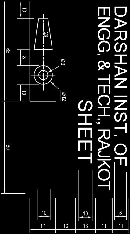
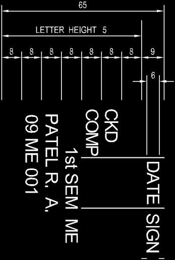
13 Practice Work INSTRUCTIONS: 1. All the Lettering must be in CAPITAL only 2. Letter height for Main Title = 10 mm, Sub Title = 8 mm, Detail = 5 mm SECTION 5 SCALES 1983/ISO 5455:1979 SCALES FOR USE ON TECHNICAL DRAWINGS CATEGORY ENLARGEMENT SCALE RECOMMENDED SCALES 50 : 1 20 : 1 10:1 5:1 2:1 FULL SIZE 1 : 1 REDUCTION SCALE 1:2 1:5 1:10 1 :20 1:50 1:100 1 :200 1:500 1:1000 Note In exceptional cases where for functional reasons the recommended scales cannot be applied, intermediate scales may be chosen. Darshan Institute of Engineering & Technology, Rajkot i
14 Engineering Graphics ( ) Practice Work TYPES OF LINES: Darshan Institute of Engineering & Technology, Rajkot ii
15 Practice Work Engineering Graphics ( ) USES OF LINES: Darshan Institute of Engineering & Technology, Rajkot iii
16 Engineering Graphics ( ) Practice Work LETTER & NUMBER: Darshan Institute of Engineering & Technology, Rajkot iv
17 Practice Work Engineering Graphics ( ) DIFFERENT ANGLE: Darshan Institute of Engineering & Technology, Rajkot v
18 Engineering Graphics ( ) Practice Work POLYGON: Darshan Institute of Engineering & Technology, Rajkot vi
19 Practice Work Engineering Graphics ( ) DIMENSIONING SYSTEM: 1. ALINGNED SYSTEM: 2. UNIDIRECTION SYSTEM: Darshan Institute of Engineering & Technology, Rajkot vii
20 Engineering Graphics ( ) Practice Work HOW TO DRAW POLYGONS BY THE UNIVERSAL METHOD OF POLYGON PROCEDURE: Step-1 First draw a line AB of the dimension equal to the side of a polygon. i.e., 50 mm. Step-2 Then draw a perpendicular bisector of the line AB and draw it of sufficient length. Step-3 Draw a perpendicular line BC from B of the length equal to the line AB. Step-4 Connect the two points A & C by a straight line. i.e., AC Step-5 Draw an arc by the center B and radius equal to AB between the points A & C. Step-6 Mark the point 4 at the intersection of line AC with the perpendicular bisector. Step-7 Mark the point 6 at the intersection of the arc AC with the perpendicular bisector. Step-8 Find out the midpoint of between the points 4 & 6 mark it as a point 5. Step-9 Mark points 7 & 8 at the distance equal to 4-5 or 5-6 in sequence. Step-10 Draw a triangle ABC by connecting the line AC & BC at point 6. Step-11 Draw circles by taking the points 4, 5,6,7,8 as center points and divide the respective circles with the compass measurement equal to the distance of the line AB. i.e., 50 mm. Step-12 Connect the divided points of respective circles in sequence with straight lines to get respective polygons. Like Square, Pentagon, Hexagon, Heptagon and Octagon. Step-13 Give the dimensions by any one method of dimensions and give the name of the components by leader lines wherever necessary. Darshan Institute of Engineering & Technology, Rajkot viii
21 1. Introduction to Engineering Graphics 1. Give the dimension of Title block and list the information given in it. 2. Divide a line PQ 100 mm long into six equal parts. 3. Without using protractor draw a regular pentagon of 40mm side. Scale 4. Define representative fraction. What is difference between plain scale and diagonal scale? 5. If the distance of 300 km is represented as 15 cm on the map find representative fraction. 6. Draw Figure shown below in Half Scale. Plain Scale 7. Construct a plain scale of R.F. = 1:50 to show meters and decimeters and long enough up to 8 meter. Indicate 6.7 m distance on scale. 8. Construct a plain scale with RF = 1/5 to show decimeters (dm) and centimeters. The scale should be long enough to measure 1 m. Show the length of 7.4 dm on it. 9. Construct a plain scale in which 1 cm represents 5 kms. It should be long enough to measure a distance of 95 kms indicate 76 kms in it. 10. On a map of a state, 1 cm represents 5 kms. Construct a plain scale long enough to measure a distance between two city 100 kms far from each other. 11. The distance between two places is 240 km and its equivalent distance on map is 12 cm. Draw plain scale & indicate 270 km and 120 km. 12. Construct a plain scale to show kilometers and hectometers when 25 mm is equal to 1 km and long enough to measure up to 6 km. Find RF and show a distance of 3km and 4 hectometer on the scale. 13. The length of the khandala tunnel on the Mumbai Pune express way is 330 meter on the road map. It is shown by 16.5 cm long line. Construct a plain scale to show meters and to measure up to 400 meter. Show the length of 290 meter long on the express way. 14. On map of Ahmedabad city 1 cm represents 1 Km. Construct a plain scale to measure the distance between Gujarat Technological University and Lal Darwaja which is 6 Km. Also indicate Darshan Institute of Engineering & Technology, Rajkot 1.1
22 Engineering Graphics ( ) 1. Introduction to EG on scale, the distance between Geeta mandir and Kankariya lake which is 3 Km and 7 hectameters. Diagonal Scale 15. Construct a diagonal scale of representative fraction = (1/36) showing yard, foot and inch. Scale should be long enough to measure 5 yard.. Measure 3 yard, 2 foot, and 9 inch. 16. The distance between Ahmedabad and Bombay is 500 km. It is represented on a railway map by 10 cm. Construct a diagonal scale to measure kilometers. Show on scale the distance between Ahmedabad and Surat which is 237 km. 17. The distance between Rashtrapatibhavan and Fort is 5.00 km. It is represented on a Delhi city map by 10 cm. Construct a diagonal scale to measure a kilometer and its fraction up to two decimal. Show on the scale the distance between Rashtrapatibhavan and India Gate which is 1.73 km. Isometric Scale 18. Draw an Isometric scale long enough to measure 12 cm. 19. A customer asked the shopkeeper to give an Aluminum sheet of 1m X 1m. Shopkeeper gave the sheet by measuring with isometric scale. How much percentage less sheet is given by shopkeeper to customer? Darshan Institute of Engineering & Technology, Rajkot 1.2
23 2. Engineering Curves 1. Explain the terms: (i) Eccentricity (ii) Involute (iii) Hypocycloid Ellipse 2. Construct an ellipse when the distance of the focus from the directrix is equalto 60 mm and eccentricity is 2/3. 3. Draw an ellipse if the distance of focus from the directrix is 70mm and the eccentricity is 3 / Construct the ellipse if the distance between the focus and the directrix is 50 mm. &the eccentricity is 2/3. Draw the tangent and the normal to the ellipse at given point. 5. Draw an ellipse having major axis 120 mm and minor axis 80 mm. UseArc of circle method. 6. Construct an ellipse by arcs of circle method. The major and minor axes are 140 mm & 100 mm respectively. Also draw the tangent and normal to the ellipse at any suitable point. 7. Draw an ellipse by an oblong method given the major and minor axes as120 mm and 90 mm respectively. 8. A Fish pond of elliptical shape is to be inscribed inside a rectangular plot of size 100m X 50m. Draw the boundary line of fish pond (use suitable scale) 9. Construct an ellipse in a parallelogram 125mm x 90mm sides. Take included angles of parallelogram as 120 and 60. Determine its major and minor axis. 10. Two points A and B are 100 mm apart. Third point C is 75mm froma and 50mm from B. Draw an ellipse passing through A, B &C. 11. The foci of an ellipse are 120 mm apart and the minor axis is 70 mm long. Draw the ellipse by concentric circle method. 12. The major axis and the minor axis of Ellipse are 125 mm and 75 mm. Construct half ellipse by Oblong method and another half byconcentric circle method. 13. The foci of an ellipse are 110 mm apart. The minor axis is 70 mm long. Determine the length of major axis and draw half ellipse by rectangle method and other half by concentric circle method. Parabola 14. Construct a parabola, when the distance of the focus from the directrix is 50mm and draw tangent and normal to the curve. 15. Construct the parabola of the base 105 mm and the axis length 98 mm using rectangle method. Locate focus, vertex and directrix of the parabola. Also draw tangent and normal to the parabola. 16. Construct a parabola having base length 100mm and axis height 60mm by tangent method. Darshan Institute of Engineering & Technology, Rajkot 2.1
24 Engineering Graphics ( ) 2. Engineering Curves 17. A throw of ball from boundary of a cricket ground reaches the wicket keeper s gloves following the parabolic path. Maximum height achieved by the ball above the ground is 31m. Assume the point of throw and point of catching position 1m above the ground. Radial distance of boundary from wicket keeper is 75m. Construct the path of ball. Hyperbola 18. Draw a hyperbola having eccentricity 8:5, the vertex V of which is at a distance of 25mm from the directrix AB. Find at least 8 points to draw the curve. Find the distance of the focus F from the directrix. Also draw a normal and a tangent to the curve at a distance 52mm from the focus. 19. A point P is 20mm and 30mm respectively from two straight lines which are at right angles to each other. Draw a rectangular hyperbola from P within 6mm distance from each asymptote line. Cycloid 20. A wheel of the diameter 50 mm rolls over the straight line without slipping for one rotation. Draw the path traced by the point P which is initially at the point of the contact between the wheel and the straight line. Name the path traced.name the curve and also draw tangent and normal to thecurve at suitable point on the curve. 21. A rolling circle, of 60 mm diameter rolling along a straight line without slipping. Take initial position of the tracing point at the bottom of the vertical centre line of the rolling circle. Name the curve and draw tangent and normal to the curve at a point 35 mm above the directing line. 22. A wheel rolls over the horizontal straight line path and covers 1980 mm distance in one rotation. Draw the path traced by the point P which isinitially at the point of contact between the wheel and the horizontal straightline. Name the path traced by the point P. 23. A circle of 50 mm diameter rolls along the circumference of another circle of 150 mm diameter from outside. Draw the path of a point P on the circumference of the rolling circle for one complete revolution and name the curve. 24. A circle of 50 mm diameter rolls on another circle of 175 mm diameter, outside it. Trace the locus of a point on the circumference of the rolling circle for one complete revolution. Name the curve. 25. Draw and name the curve traced by a point on the perimeter of 60 mmdiameter circle if it rolls by one revolution outside the circle with 160 mmdiameter. Darshan Institute of Engineering & Technology, Rajkot 2.2
25 2. Engineering Curves Engineering Graphics ( ) 26. A circle of 60mm diameter is rolling on a circle of 120mm radius and inside it. Initially point P is at contact point of two circles. Draw the locus of point P. Draw tangent and normal at any point on the curve. 27. Show graphically that the hypocycloid is a straight line, when the diameter of the rolling circle is half that of the directing circle. Take radius of the rolling circle as 40mm. Involute 28. A string is kept tight while unwinding it from a square prism which is resting with its base on the H.P. Trace the path of the end point of the string,if 100 mm long string can be unwound in one turn. Name the path traced bythe end point of the string. 29. A string is unwound from a pentagon of 25 mm side. Draw the locus of end P for unwounding the one turn of string. String is kept tight during the operation of unwounding. Give the name of curve. Draw the tangent and normal to the curve at any point. 30. A string is unwound from a hexagon of 25 mm side. Draw the locus of end P for unwinding the one turn of string 31. Construct the Involute of circle of 30 mm diameter for one turn. Draw tangent and normal to the Involute at any point on it. 32. An elastic string is unwounded to a length of 120 mm from a drum of diameter 30 mm. Draw the locus of the free end of the string which is held tight during unwinding. 33. Draw an involute of a circular arc which subtends an angle of 90 at the centre of the circle of diameter 120 mm. 34. Draw an involute of a line of 10 mm for either minimum 3 turns or maximum 5 turns. Spiral 35. Draw an Archimedean spiral of 2/3 convolution. When maximum and minimum radii being 60mm and 20mm respectively. 36. Construct an Archimedean spiral of one and half convolutions given thegreatest and shortest radii as 84mm and the 00 mm respectively. Draw thetangent and normal at point 60 mm away from the pole. 37. Draw an Archimedean spiral of 1.5 convolutions, the greatest and least radii being 125 mm and 35 mm respectively. Draw tangent and normal to the spiral at any point on the curve. 38. A point P moves towards another point O, 75 mm from it, and reaches it during 1¼ revolution around it in clockwise direction. Its movement towards O is uniform with its movement around it. Draw the curve traced out by the point P and name it. Darshan Institute of Engineering & Technology, Rajkot 2.3
26
27 3. Projections of Points & Lines 1. Draw the projection of points, the position of as per data given below: i. A point P 25 mm above H.P. and 20 mm behind V.P. ii. A point Q 20 mm below H.P. and 25 mm behind V.P. iii. A point R 25 mm below H.P. and 20 mm in front of V.P. iv. A point S 20 mm above H.P. and 25 mm in front of V.P. v. A point T on H.P. and 25 mm in front of V.P. vi. A point U on H.P. and 25 mm behind V.P. vii. A point V on V.P. and 20 mm above H.P. viii. A point W on V.P. and 20 mm below H.P. ix. A point X on H.P. as well as V.P. both. Position of an End Point & Inclination with H.P. & V.P. & TL 2. A line AB 75 mm long is inclined at an angle of 45ᵒ to H.P. and 30ᵒ to V.P.. One of its end point A is in H.P. as well as V.P.. Determine its apparent inclination with V.P.. T.L.= θ = L.F.V.= α = L.E.P. = φ = L.T.V.= β = 3. A line AB, 80mm long, is inclined to H.P. by 30ᵒ and inclined to V.P. by 45ᵒ. The line is in first quadrant with point A 15mm above H.P. and 30mm in front of V.P.. Draw the projection of line AB. T.L.= θ = L.F.V.= α = L.E.P. = φ = L.T.V.= β = Darshan Institute of Engineering & Technology, Rajkot 3.1
28 Engineering Graphics ( ) 3. Projections of Points & Lines 4. A line AB is 80 mm long. It is inclined at an angle of 45 to the Horizontal Plane and 30 to the Vertical Plane. The end A is 20 mm above Horizontal Plane and 40 mm in front of Vertical Plane. Draw the projections of the line and also write Elevation Length and Plan length of the line. T.L.= θ = L.F.V.= α = L.E.P. = φ = L.T.V.= β = 5. A line PQ, 65 mm long, is inclined to H.P. by 30 and inclined to V.P. by 45. The end P is 20 mm below H.P. and 25 mm behind V.P. Point Q is in fourth quadrant. Draw its projections and find the position of the point Q. T.L.= θ = L.F.V.= α = L.E.P. = φ = L.T.V.= β = 6. A straight line AB is inclined to the H.P. by 30ᵒ and to the V.P. by 60ᵒ, if true length of line is 100 mm. The end A is 10 mm above H.P and 25 mm infront of V.P. find lengths of plan and elevation of the line and draw the projections. T.L.= θ = L.F.V.= α = L.E.P. = φ = L.T.V.= β = 7. A line PQ, 80 mm long has its end P 15 mm above the H.P. Line makes an angle of 30ᵒ with the H.P. and 45ᵒ with the V.P. End Q of the line is 10 mm in front of V.P. Draw the projections of the line considering it in first quadrant. T.L.= θ = L.F.V.= α = L.E.P. = φ = L.T.V.= β = Position of Mid-Point is given 8. A line AB, 80 mm long is inclined at 45ᵒ to H.P. and 30ᵒ to V.P.. Its midpoint C is in V.P. and 15 mm above H.P.. The end A is in the third quadrant and B in the first quadrant. Draw the projections of the line. T.L.= θ = L.F.V.= α = L.E.P. = φ = L.T.V.= β = Darshan Institute of Engineering & Technology, Rajkot 3.2
29 3. Projections of Points & Lines Engineering Graphics ( ) 9. A straight line AB 80 mm long is inclined at 30 to the H.P. and at 45 to the V.P.. Its midpoint C is in the V.P. and 18 mm above the H.P., while its end A is in the third quadrant, and the end B is in the first quadrant. Draw its projections. T.L.= θ = L.F.V.= α = L.E.P. = φ = L.T.V.= β = Position of End Points & TL 10. A line AB 75 mm long has its end point A 15 mm above H.P. and 10 mm in front of V.P. and end point B 45 mm above H.P. and 50 mm in front of V.P.. Determine true inclination of line AB with H.P. and V.P. T.L.= θ = L.F.V.= α = L.E.P. = φ = L.T.V.= β = 11. A line AB, 75 mm long, has its end A 20mm below H.P. and 25 mm behind V.P. The end B is 50 mm below H.P. and 65 mm behind V.P. Draw the projections of line AB and find its inclinations with H.P. and V.P. T.L.= θ = L.F.V.= α = L.E.P. = φ = L.T.V.= β = Position of End Points & Distance between End Projectors 12. The projectors of the ends of a line AB are 50 mm apart. The end A is 20 mm above horizontal plane and 30 mm in front of the vertical plane. The end B is 10 mm below the H.P. and 40 mm behind the V.P. Determine the true length of line AB, its inclinations with H.P. and V.P. and apparent angles also. T.L.= θ = L.F.V.= α = L.E.P. = φ = L.T.V.= β = 13. The distance between end projectors of a straight line PQ is 130 mm point P is 40mm below H.P. and 25 mm in front of V.P. Point Q is 75mm above H.P. and 30 mm behind V.P. Draw the projection of a line and find out its true length and inclination with H.P. and V.P. T.L.= θ = L.F.V.= α = L.E.P. = φ = L.T.V.= β = Darshan Institute of Engineering & Technology, Rajkot 3.3
30 Engineering Graphics ( ) 3. Projections of Points & Lines 14. The distance between end projectors of a straight line CD is 65 mm. The point C is 30 mm above H.P. and 25 mm behind V.P. The point D is 40 mm above H.P. and 20 mm in front V.P. Draw the projections of straight line CD. Through which principal plane the straight line will pass and what will be the distance of the point of intersection of line from the other principal plane? T.L.= θ = L.F.V.= α = L.E.P. = φ = L.T.V.= β = 15. A line CD has its end C is 15mm above H.P. and 10mm in front of V.P. The end D is 60mm above H.P. The distance between the end projectors is 50mm. The line is inclined to H.P. by 25ᵒ. Draw the projections and find its inclination with V.P. and true length of line CD. T.L.= θ = L.F.V.= α = L.E.P. = φ = L.T.V.= β = 16. A line PQ has its end P 15 mm above H.P. and 10 mm in front of V.P. The end Q is 60 mm above H.P. The distance between the end projectors is 55 mm. The line is inclined to H.P. by 25 degree. Draw the projections and find its inclination with V.P. and true length of line PQ. T.L.= θ = L.F.V.= α = L.E.P. = φ = L.T.V.= β = Position of an End Point or Length of FV/TV or Inclination with H.P./V.P. or inclination of FV/TV 17. The top view of 75 mm long line AB measures 65 mm, while the length of its Front view is 50 mm. Its one end A is in the H.P. and 12 mm in front of the V.P. Draw the projections of line AB and its inclinations with the H.P. and the V.P. T.L.= θ = L.F.V.= α = L.E.P. = φ = L.T.V.= β = 18. A line AB 65 mm long appears to be 55 mm in plan and 45 mm in elevation. Its end A is 20 mm below H.P. and 40 mm behind V.P. Draw projections of a line and find the true angle of inclinations of line with H.P. and V.P. T.L.= θ = L.F.V.= α = L.E.P. = φ = L.T.V.= β = Darshan Institute of Engineering & Technology, Rajkot 3.4
31 3. Projections of Points & Lines Engineering Graphics ( ) 19. The top view and the front view of the line EF, measures 65 mm and 53 mm respectively. The line is inclined to H.P. and V.P. by 30ᵒ and 45ᵒ, respectively. The end E is on the H.P. and 10 mm in front of V.P.. Other end F is in the 1st quadrant. Draw the projections of the line EF and find its true length. T.L.= θ = L.F.V.= α = L.E.P. = φ = L.T.V.= β = 20. A line AB is having its end A 10 mm, above H.P. and 30 mm in front of V.P. It is inclined at 45 to H.P. and 30 to V.P. The end B is below H.P. and behind V.P. Draw the projections of the line AB if the plan length is 80 mm. Also, find the true length of the line. T.L.= θ = L.F.V.= α = L.E.P. = φ = L.T.V.= β = 21. A line is measuring 80 mm long has one of its end 60 mm above H.P. and 20 mm in front of V.P. The other end is 15 mm above H.P. and in front of V.P. The front view of the line is 60 mm long. Draw the projection of line and find the true angle of inclination of line with H.P. and V.P. T.L.= θ = L.F.V.= α = L.E.P. = φ = L.T.V.= β = 22. A line AB, 100 mm long, is inclined at 50 o to Horizontal Plane. The end A is 10 mm above the Horizontal Plane and end is 65 mm in front of the Vertical Plane. Draw projections of the line if its Front View measures 90 mm and find the inclination of the line with the Vertical Plane. T.L.= θ = L.F.V.= α = L.E.P. = φ = L.T.V.= β = 23. The front view of a line AB, 90mm long, measures 65mm. Front view is inclined to XY line by 45. Point A is 20 mm below H.P. and on V.P. Point B is in third quadrant. Draw the projections and find Inclinations of line with H.P. and V.P. T.L.= θ = L.F.V.= α = L.E.P. = φ = L.T.V.= β = 24. Plan of a 75 mm long line CD measures 50mm. End C is in H.P. and 50mm in front of V.P. End D is 15 mm in front of V.P. and it is above H.P. Draw projections of CD and find angles with V.P. and H.P. Darshan Institute of Engineering & Technology, Rajkot 3.5
32 Engineering Graphics ( ) 3. Projections of Points & Lines T.L.= θ = L.F.V.= α = L.E.P. = φ = L.T.V.= β = 25. A line AB 90 mm long is inclined at 30º to the H.P. Its end A is 12 mm above the H.P. and 20 mm in front of V.P. Its front view measures 65 mm. Draw the top view of AB and state its length. Determine the inclination of top view and line AB with V.P. T.L.= θ = L.F.V.= α = L.E.P. = φ = L.T.V.= β = 26. A line AB, 100 mm long, is inclined at 45 0 to H.P. The end A is 10 mm above the H.P. and is 65 mm in front of the V.P. Draw projections of the line if its Front View measures 90 mm and find the inclination of the line with the V.P. T.L.= θ = L.F.V.= α = L.E.P. = φ = L.T.V.= β = 27. The front view and top view of a line MN is inclined at an angle of 30 o and 40 o respectively. The front view of line MN measures 50 mm. Point M is 15 mm above H.P. and 10 mm in front of V.P. Draw the projections of line MN and find the true length of line MN. T.L.= θ = L.F.V.= α = L.E.P. = φ = L.T.V.= β = Miscellaneous 28. A straight line AB has its end A 10 mm above H.P. and end B 50 mm in front of the V.P. Draw the projections of line AB, if it is inclined to H.P. by 30ᵒ and to V.P. by 45ᵒ and it is 50 mm long. T.L.= θ = L.F.V.= α = L.E.P. = φ = L.T.V.= β = 29. A line PQ 70 mm long has its end P in V.P. and end Q in H.P.. Line is inclined to H.P. by 60ᵒ and V.P. by 30ᵒ.Draw the projections. T.L.= θ = L.F.V.= α = L.E.P. = φ = L.T.V.= β = 30. A line PQ 60 mm long has its end P on V.P and Q on H.P. Line is inclined to H.P. by 60ᵒ and V.P. by 30ᵒ and it is 20 mm away from the profile plane. Draw the projections of the line. Darshan Institute of Engineering & Technology, Rajkot 3.6
33 3. Projections of Points & Lines Engineering Graphics ( ) T.L.= θ = L.F.V.= α = L.E.P. = φ = L.T.V.= β = 31. A line AB measures 80 mm in top view and 70 mm in front view. The midpoint M of the line is 45 mm in front of V.P. and 35 mm above H.P. The end A is 10 mm in front of V.P. Draw the projections of the line and find its true length and inclination with H.P. and V.P. T.L.= θ = L.F.V.= α = L.E.P. = φ = L.T.V.= β = 32. The line AB has end A in front of V.P. and 30 mm above H.P, while end B is in V.P. and 20 mm below H.P. The line is inclined at 30ᵒ to the V.P. and the apparent angle in elevation is 30ᵒ. Draw the projections of the line AB. Find the true length, the elevation length and the plan length of the line. Measure the inclination of the line with the H.P. T.L.= θ = L.F.V.= α = L.E.P. = φ = L.T.V.= β = 33. A line AB has a point P on it such that AP: PB = 1: 2. The end A is in the first quadrant and it is 20 mm above H.P. while the end B is in the V.P. The point P is 35 mm from the H.P. The line is inclined at 30ᵒ to the H.P. and the elevation length of the line is 70 mm. Draw the projections of the line AB and the point P. Find the true length, the plan length and the inclination of the line with V.P. T.L.= θ = L.F.V.= α = L.E.P. = φ = L.T.V.= β = Darshan Institute of Engineering & Technology, Rajkot 3.7
34
35 4. Projections of Plane 1. An isosceles triangular plane XYZ having its base XY = 50 mm and altitude 60 mm is resting on HP on its base XY with its surface making an angle of 45ᵒ to HP. The base XY which is in HP makes an angle of 60ᵒ to VP. Draw projection of plane. 2. An isosceles triangle plate ABC having its base 50 mm and altitude 90 mm resting on H.P. on its base. The isosceles triangle is inclined at an angle 50 to the H.P. and the altitude in the top view is inclined at the angle 70 to the V.P. Draw the projections. 3. A semi-circular thin plate of 60 mm diameter rests on H.P. on its diameter, which is inclined at 45ᵒ to V.P. and the surface is inclined at 30ᵒ to the H.P. Draw the projections of the plate. 4. A circular plane of 60 mm diameter is resting on H.P. on a point A of its circumference. The plane (surface) is inclined at 30ᵒ to the H.P. The diameter AB of the plane makes an angle of 45ᵒ with the V.P. Draw the projections of the circular plane. 5. A square lamina of side 35 mm is resting on HP on one of its sides such that the surface of the lamina is inclined at 40 to HP. Draw its top view and front view when the side on which it rests is parallel to VP. 6. A regular pentagonal plane having the side 30 mm is resting on H.P. on one of its corners. The surface of the plane is inclined to the H.P. at 45ᵒ. Draw the projections of the plane when the side opposite to the corner on which it rest on H.P. is inclined at 30ᵒ to V.P. OR A pentagon plate, side 30mm is resting on H.P. on one of its corners with opposite edge to the corner making 30ᵒ with V.P. The plate (surface) is inclined to H.P. by 45ᵒ. Draw its projections. 7. ABCDE is a regular pentagonal plate of 40mm sides, has its corner A on the H.P. the plate is inclined at 30 to the H.P. such that the side CD is parallel to both the reference planes. Draw the projection of plate. 8. A pentagon plate, side 40mm is resting on H.P. on one of its corners. The plate is inclined to H.P. by 45 and perpendicular to VP. Draw its projections. 9. A hexagonal plate (30 mm) is resting on one of its side on H.P. The side on which it rests makes an angle of 60ᵒ with V.P. and the plate makes an angle of 45ᵒ with H.P. Draw the projections of the plate. 10. A Pentagonal plane of side 50 mm is kept on the HP on one of its side in such a way that its surface makes an angle of 45ᵒ with HP. Draw the projection of plane when side which is in HP is inclined at 60ᵒ with VP in such a way that nearest corner point is at a distance of 20 mm from VP. Darshan Institute of Engineering & Technology, Rajkot 4.1
36 Engineering Graphics ( ) 4. Projections of Plane 11. A square plate PQRS of side 35 mm is resting on corner P on H.P. with diagonal PR making 30ᵒ with H.P. and diagonal QS inclined to V.P. by 60ᵒ and parallel to H.P. Draw the projections of the square plate. 12. A Pentagonal plate having 30mm side is resting on V.P on one of its corner plate (surface) makes 45 0 with V.P. The side opposite to the corner on which it rest makes 30 0 with H.P. Draw its projection. 13. A thin 30º-60º set square has its longest edge is 80 mm in the VP and inclined at 45º to the HP. Its surface makes an angle of 60º with the VP. Draw its projections. 14. A regular pentagon of 30mm side has one side parallel to the V.P. and making an angle of 40 with the H.P. the plane surface of the pentagon make 35 the V.P. Draw its projections. 15. A regular pentagonal plate is resting in V.P. on one of its sides with surface making an angle 45 with V.P. The side on which it rests on V.P. makes 60 with H.P. Draw the projections of pentagonal plate having the side 30mm. 16. A circular plate of negligible thickness having 70mm diameter is resting on HP on a point of the circumference. Plate is kept perpendicular to VP and inclined to the HP such that the plan of it is an ellipse of minor axis 40mm. Draw the projections. 17. A square plate of side 60mm is held on a corner on H.P Plate is inclined to the H.P. such that the plan of it is rhombuses with a diagonal of 30mm. determine the angle it makes with H.P. The other diagonal is inclined at 45 V.P. Draw the projection of plate. 18. A square plate of side 40 mm is rest on one of its corner on H.P. with diagonal horizontal and inclined at 50 to V.P. The Plate is seen as a rhombus in plan with one of its diagonals measuring 30 mm. Draw the projections. 19. ABCD is a rhombus of diagonals AC =100 mm and BD=70 mm. Its corner A is in the H.P. and the plane is inclined to the H.P. such that its plan appears to be a square and the plan of the diagonal AC makes an angle of 20 to the V.P. Draw the projections of the plane and find its inclination with the H. P. 20. A circular plate of negligible thickness and 46 mm diameter appears as an ellipse in the top view, having its major axis 46 mm long and minor axis 28 mm long. Draw its front view when the major axis of ellipse makes an angle of 60ᵒ to V.P. 21. An elliptical plane with major axis 70 mm and minor axis 50 mm is inclined to H.P. such that the top view of the plane is a circle. Draw the projections of the plane when the major axis is inclined at 30ᵒ to the V.P. Find the inclination of the plane with the H.P. Use the concentric circle method to draw the top view of the plane in the initial stage. Darshan Institute of Engineering & Technology, Rajkot 4.2
37 4. Projections of Planes Engineering Graphics ( ) 22. An Elliptical plane of major axis 70mm and minor axis 50mm is resting on H.P on one end point of major axis. It appears as circle in the top view. Minor axis makes 45 0 with V.P. Draw its projection. 23. The top plan of a pair of equal legs AB and AC of compass appears as an isosceles triangle having base 50 mm and vertex angle at 45ᵒ.Actual lengths of compass legs AB and AC are 120 mm. Assume points B and C on H.P. and line connecting B and C is perpendicular to V.P. Draw the projections and find (I) the actual angle between two legs (ii) the height of point above HP and (iii) angle of plane, containing compass, makes with H.P. 24. A thin rectangular plate of 60 x 30 mm has its shorter side in the V.P. and inclined at 30ᵒ to the H.P. Project its top view, if its front view is a square of 30 mm long sides. 25. A rhombus is having its diagonals 100 mm and 50 mm long. Draw the projections of the rhombus when the longer diagonal is inclined at 30 to the Horizontal Plane and 30 to Vertical Plane. 26. A Square plate, side 40 mm, is resting on H.P with one side of plate inclined to V.P. by 30. Draw the projections. 27. An isosceles triangular plate ABC has its base 45 mm and altitude 60 mm. It is so placed that the front view is seen as an equilateral triangle of 45 mm side and (i) base is inclined at 45ᵒ to HP, (ii) side is inclined at 45ᵒ to HP. Draw its plan when its corner A is on HP. Darshan Institute of Engineering & Technology, Rajkot 4.3
38
39 5. Projections & Sections of Solids Projections of Solids Axis/Base Edge are inclined to HP/VP 1. A pentagonal prism rests on one of its edges of the base on H.P. with its axis inclined at 45º to the H.P. The top view of the axis is inclined at 30º to the V.P. Draw the projections of the prism, assuming the edge of the base to be 30 mm and the axis 70 mm long. 2. A pentagonal pyramid is having its base ABCDE and the apex O. The length of the axis is 80 mm and the edge of base is 30 mm. The pyramid is resting on the H.P. with the edge CD on it. Draw the projections when the axis of the pyramid is inclined at 30 0 to the H.P. and the plan of the axis of the pyramid makes 45 0 with the V.P. 3. Draw the projection of cylinder, base 30 mm diameter and axis 40 mm long, rests with a point of its base circle on H.P. such that the axis is making an angle of 30 o with H.P. and its top view perpendicular to V.P. 4. Draw the projection of a cone, base 44 mm diameter and axis 50 mm long, when it is resting on the H.P. on a point of its base circle with the axis making an angle of 45 o with H.P. and 30 o with V.P. 5. A cone diameter of base 60 mm and height 90 mm is resting on H.P. on the point of periphery of the base. Axis of the cone makes 60 degree with the H.P. and 30 degree with the V. P. Draw the projections of the cone, when the apex is nearer to observer. 6. A square pyramid, side of the base 40 mm and axis 60 mm long, has one of its base edges in the H.P. and axis inclined at 30 to the HP. Draw its projections when a) the top view of the axis makes an angle 45 with the V.P. and b) the axis makes an angle of 45 with the V.P. 7. A square prism, having base 30 mm side and axis 50 mm long, has its axis inclined at 45 o to the H.P. and has an edge of its base on the H.P. and inclined at 30 o to the V.P. Draw the projection. 8. A Hexagonal prism is resting on one of its side of base (30mm), such that axis(60mm) is inclined at 45 to H.P. and the side on which it is resting is inclined at 30 to V.P. Draw the projections. 9. A Square pyramid, side of base 50 mm and axis length 60 mm is kept on HP on one of its base edges in such a way that its axis makes an angle of 45o with HP. If the base edge which is on HP makes an angle of 45o with VP, draw the projections when apex is 30 mm away from VP. Triangular surface is inclined to HP/VP 10. A pentagonal pyramid has height 60 mm and the side of a base 30 mm. The pyramid rests on one of its sides of the base on the H.P. such that the triangular face containing that side is perpendicular to the H.P. and makes an angle of 45 degree with the V.P. Draw its projections. Darshan Institute of Engineering & Technology, Rajkot 5.1
40 Engineering Graphics ( ) 5. Projections & Sections of Solids 11. A hexagonal pyramid, side of the base 25 mm long and height 70 mm resting on HP on its side, has one of its triangular faces perpendicular to the HP and inclined at 60º to VP. Draw its projections. 12. A tetrahedron of 50mm edge is resting on H.P on one of its edge. Face passing through that edge is perpendicular to H.P and parallels to V.P. Draw its projections. 13. A pentagonal pyramid of 35 mm base edge and 70 mm height is resting on the Horizontal Plane with one of its triangular surfaces perpendicular to the Horizontal Plane and parallel and nearer to Vertical Plane. Draw its projections. 14. A Pentagonal pyramid, side of the base 35 mm and height 70 mm is resting on HP on its side, has one of its triangular faces perpendicular to the HP and VP both. Draw its projections. Slant edge is inclined to HP/VP 15. A hexagonal pyramid, base 25 mm side and axis 55 mm long, has one of its slant edges on the H.P. A plane containing that edge and the axis is perpendicular to the H.P. and inclined at 450 to the V.P. Draw its projections when the apex is nearer to V.P. than the base. 16. ABCD is tetrahedron of 60 mm long edge. The edge AB is in the H.P. The edge CD is inclined at an angle of 30 0 to the H.P. and 45 0 to the V.P. Draw the projections of the tetrahedron. 17. A pentagonal prism is resting on one of the corner of its base on the H.P. The longer edge containing that corner is inclined at 45 to the H.P. The axis of the prism makes an angle of 30 to the V.P. Draw the projections of the solid. Miscellaneous 18. A cube with a 30mm side resting on one of its corners on the HP. Draw the projections when the base is inclined at 45º to HP and axis parallel to VP. 19. A frustum of a cone, having base diameter 60 mm, top base diameter 25 mm and axis 45 mm, is resting on one of its generators on H.P. The axes of the frustum makes and angle of 300 with V.P. Draw the projections of the solid. 20. A circular cone is of 60 mm base diameter and 80 mm long generator. It i s resting on the H.P. with one of the points of its base on it and the apex 55 mm above it. Draw the projection of the cone when the plan of the axis is inclined at 45 0 to the V.P. Measure the inclination of the cone with the H.P. 21. A square pyramid, side of base 50 mm and height 64 mm, is freely suspended from one of the corners of the base. Draw its projection when vertical plane containing the axis makes an angle of 45 o to VP. Darshan Institute of Engineering & Technology, Rajkot 5.2
41 5. Projections & Sections of Solids Engineering Graphics ( ) Sections of Solids Cut by Auxiliary Inclined Plane 22. A square pyramid, base 40 mm side and axis 65mm long, has its base on the H.P. And all the edges of the base equally inclined to the V.P. It is cut by a section plane perpendicular to the V.P. inclined at 45 to the H.P. and bisecting the axis. Draw its sectional top view, sectional side view ant true shape of the section. 23. A pentagonal prism of side length of base 30 mm and height 60 mm is resting on HP with one edge of base perpendicular to VP. It is cut by an Auxiliary Inclined Plane included at 40º to HP and bisecting the axis. Draw sectional top view, sectional side view and true shape of the section. 24. A hexagonal Prism, side of base 30 mm and height 60 mm, is standing upright with base on H.P. one side of the base and axis are parallel to V.P. It is cut by section plane making an angle of 60 0 to H.P. and crossing the axis 10 mm from the top. Draw top view, sectional front view, sectional left hand side view and true shape of section. 25. A pentagonal pyramid, side of base 40 mm and height 80 mm, is resting on its base with one of the edges of the base away from V.P. is parallel to V.P. It is cut by an AIP bisecting the axis, the distance of the section plane from the apex being 20 mm. Draw the elevation and sectional plan of pyramid and draw the true shape of the section. Also find the i nclination of the section plane with the H.P. 26. A cone having the diameter of base 80 mm and the height 90 mm is resting with its base on the H.P. It is cut by A.I.P. inclined at 450 to the H.P. The cutting plane passes through the mid-point of the axis of the cone. Draw the elevation, the sectional plan and the true shape of the section. 27. A cone, base 75 mm diameter and axis 80 mm long is resting on its base on the H.P. It is cut by a section plane perpendicular to the V.P., inclined at 45 0 to the H.P. and cutting the axis at a 35 mm from the apex. Draw front view, sectional top view and true shape of the section. Cut by Auxiliary Inclined Plane (Base cut) 28. A solid made of half cone, diameter of base 60 mm, and half hexagonal pyramid, side of base 30 mm, is having 60 mm height. It is resting on HP on its base with middle edge of base perpendicular to VP. It is cut by an AIP inclined at 30o to HP, passing through a point on axis 12 mm above the base. Draw elevation, plan and true shape of the section. 29. A cone, base 40 mm diameter and axis 60 mm long, rests on its base on the HP. It is cut by a section plane perpendicular to the VP and parallel to one of its generators and passing through a Darshan Institute of Engineering & Technology, Rajkot 5.3
42 Engineering Graphics ( ) 5. Projections & Sections of Solids point on the axis at a distance of 25 mm from the apex. Draw the front view, sectional top view, sectional side view and the true shape of the section. Give the name of that True shape. Cut by Auxiliary Vertical Plane 30. A hexagonal pyramid of the base side 30 mm and axis length 70 mm is resting on H.P. with its base on it and one of the sides of the base parallel to V.P. The axis of the pyramid is 40 mm away from the V.P. The pyramid is cut by the A.V.P. inclined at 300. The cutting plane is 15 mm away from the axis and nearer to the observer. Draw the top view, sectional front vi ew and the true shape of the section. 31. A cone with base circle diameter 60 mm and axis length 75 mm is kept on its base on the ground. It is cut by a sectional plane perpendicular to HP and inclined at 600 to VP at a distance of 8 mm away from the top view of axis. Draw sectional elevation and true shape of the section. 32. A frustum of hexagonal pyramid, side of base 30 mm and height 60 mm, is cutting from a pyramid of height 80 mm, is standing upright with base on H.P. and axis parallel to V.P. It is cut by section plane making an angle of 50o to V.P. and remaining 20 mm away from the axis. Draw top view, sectional front view, sectional left hand side view and true shape of section. Combined projection and section cut by AIP 33. A cone diameter of base 50 mm and height 80 mm is resting on the H.P. on one of its generators with axis parallel to the V.P. It is cut by horizontal section plane passing through a point on the axis 55 mm away from the apex. Draw the elevation and sectional plan of cone. 34. A cone, having diameter of base 50 mm and axis 65 mm long, is lying on the ground on one of its generator with the axis parallel to V.P. It is cut by a horizontal section plane 12 mm above the H.P. Draw its sectional top view. 35. A triangular prism, with a base side of 50 mm and an axis length of 70 mm, is resting on a rectangular face on the HP, the axis being parallel to the VP. An AIP inclined at 450 to the HP cuts the prism. The cutting plane intersects the axis at a distance of 30 mm from one end of the prism. Draw Front View, Sectional Top view and sectional side view of the prism 36. A hexagonal pyramid of side of base 40 mm and height of axis 110 mm is resting on one of its inclined vertical surface on H.P. such that its axis remains parallel to the V.P. It is cut by a cutting plane which is inclined at an angle 45 with H.P. and bisecting the axis of the pyramid. Draw front view, sectional top view. Darshan Institute of Engineering & Technology, Rajkot 5.4
43 5. Projections & Sections of Solids Engineering Graphics ( ) Combined projection and section cut by AVP 37. A cylinder, diameter of base 75 mm and axis 84 mm is resting on one of its generator on the H.P. with its axis remaining parallel to V.P. It is cut by an A.V.P. inclined to the V.P. by 45 0 and passing through the midpoint of the axis of the cylinder. Draw sectional elevation, sectional end view and plan showing the cutting plane. 38. A hexagonal pyramid is resting on one of its triangular face on H.P. with axis remaining parallel to V.P. It is cut A.V.P. making 300 with V.P. passing through a point on the axis 33 mm from the apex. Draw plan, sectional elevation and the true shape of section. Take side of base 30 mm and height 75 mm. 39. A pentagonal pyramid, base 30 mm side and axis 60 mm long, is lying on one of its triangular faces on the H.P. with axis parallel to the V.P. A vertical section plane bisects the top view of the axis and makes an angle of 30o with V.P. Draw the sectional front view Reverse Problem (True Shape is given) 40. A cone, base diameter 60 mm and axis length 60 mm is kept on H.P. on its base. It is cut by a plane in such a way that the true shape of the section is an isosceles triangle of base 40 mm. Draw front view and sectional top view. 41. A tetrahedron of 50 mm long edges is lying on HP on one of its faces with one of its edges perpendicular to VP so that the true shape of its section is an isosceles triangle of base 40 mm and altitude 28 mm. Find the inclination of the section plane with HP. Draw the front view, sectional top view and the true shape of the section. 42. A tetrahedron of 70 mm long edges is lying on Horizontal Plane on one of its faces with an edge of that face perpendicular to the Vertical Plane. It is cut by a section plane perpendicular to both the reference plane in such a way that the true shape of section is an isosceles triangle of 45 mm height. Draw elevation, plan and side view when smaller cut piece of the object is assumed to be removed. 43. A cube of 50 mm long edges has its vertical faces equally inclined to VP. It is cut by a section plane perpendicular to VP so that the true shape of the section is a regular hexagon. Determine the inclination of the cutting plane with the HP and draw the sectional top view and true shape of the section. Darshan Institute of Engineering & Technology, Rajkot 5.5
44
45 6. Orthographic Projections 1. Explain the difference between 1 st angle and 3 rd angle orthographic projection. 2. In orthographic projection why second and fourth angle projection method are not used? 3. Draw the symbols for first angle and third angle projection method 4. Draw orthographic view (i) Elevation (ii) Top view (iii) Left Hand Side View of the following figure, Use 1 st angle projection system 5. Using the Third angle projection method, draw the following view for the FIGURE-1. Give the dimensions using the Aligned dimensioning method. (i) Front view (ii) Top view (iii) Full Sectional Right Hand Side End View. Darshan Institute of Engineering & Technology, Rajkot 6.1
46 Engineering Graphics ( ) 6. Orthographic Projections 6. Refer the object shown in figure. Draw the following orthographic views using the first angle projection method. Use the Aligned System of dimensioning. (i) Front View from the direction X (ii) Top View (iii) Left Hand Side View. 7. Draw front view and top view of the object shown in figure according to third angle projection method. Darshan Institute of Engineering & Technology, Rajkot 6.2
47 6. Orthographic Projections Engineering Graphics ( ) 8. Figure shows the pictorial view of the object. Draw the sectional front view, top view and left hand side view using first angle method of projection. 9. The following figure shows pictorial view of an object. Draw to the full scale the following views, using first angle projection method. Insert all dimensions. (1). Front view looking in the direction of arrow X (2). Top view, (3). Right hand side view Darshan Institute of Engineering & Technology, Rajkot 6.3
48 Engineering Graphics ( ) 6. Orthographic Projections 10. Draw the front view, top view and left hand side view of the object given in figure. Use first angle projection method. 11. Draw Elevation and Left Hand Side View and top view of figure according to First Angle projection method. Darshan Institute of Engineering & Technology, Rajkot 6.4
49 6. Orthographic Projections Engineering Graphics ( ) 12. Following figure shows the pictorial view of the object.draw the Front view, Top view and left hand side view using first angle method of projection. 13. Refer the object shown in figure. Draw the following views using the first angle projection method. Use the unidirectional system of the dimensioning. (i) Sectional Front View (ii) Top View (iii) Right Hand Side View Darshan Institute of Engineering & Technology, Rajkot 6.5
 R.H.S. view and (iii) Top view using 1 st angle Projection Method. 15. Figure shows the pictorial view of an object. Draw the following views. (I).")
50 Engineering Graphics ( ) 6. Orthographic Projections 14. Figure shows the pictorial view of an object. Draw the following views: (i) Sectional front view from A-A, (ii) R.H.S. view and (iii) Top view using 1 st angle Projection Method. 15. Figure shows the pictorial view of an object. Draw the following views. (I). Sectional front view. (ii). Right hand side view (iii). Top view. Use first angle projection method. Darshan Institute of Engineering & Technology, Rajkot 6.6
51 6. Orthographic Projections Engineering Graphics ( ) 16. Pictorial view of an object is given in figure. Draw (i) Front View and (ii) Full Sectional Right Hand Side View. Insert necessary dimensions using aligned system of dimensioning. Take section along X-X. 17. Figure shows pictorial view of an object. Draw following views (a) Sectional Elevation from X (b) Plan and ( c ) Right hand side view Darshan Institute of Engineering & Technology, Rajkot 6.7
52 Engineering Graphics ( ) 6. Orthographic Projections 18. Figure shows the three dimensional pictorial view of an object. Draw using first angle projection method, front view, top view and sectional side view. 19. Draw the following views for the Figure. Give the dimensions using Aligned dimensioning method. (i)front view (ii)top view (iii)sectional left hand side view Darshan Institute of Engineering & Technology, Rajkot 6.8
53 6. Orthographic Projections Engineering Graphics ( ) 20. Figure shows the Pictorial view of an object. Draw the following views using first angle projection method (a) Sectional Front elevation looking from direction X, take section along A-A (b) Top view (c) Side view from left. Show all dimensions. 21. Figure shows an object. Draw sectional front view along section P-Q looking in the direction of arrow X, top view and sectional left hand side view along section R-S using first angle projection method. Darshan Institute of Engineering & Technology, Rajkot 6.9
54 Engineering Graphics ( ) 6. Orthographic Projections 22. Using the first angle projection method, draw the following view for the figure Give the dimensions using the Aligned dimensioning method. (i) Sectional front view by taking section along C-D (ii) Sectional left hand side view by taking section along A-B (iii) Top view Darshan Institute of Engineering & Technology, Rajkot 6.10
55 7. Isometric Projections and Isometric View or Drawing 1. Construct an Isometric scale. 2. Differentiate between Isometric View and Isometric Projections. 3. The top view of an object is a square of 60 mm side while the front view is a circle of radius 30 mm. Draw the isometric projection of the object. 4. Draw the isometric drawing of the frustum of a square pyramid when the length of the bottom edge is 60 mm, the length of the top edge is 40 mm and the height of the frustum is 70 mm. 5. Draw the isometric projection and isometric drawing of a sphere of diameter 50 mm placed on a cylinder of base 60 mm diameter and height 30 mm. 6. Explain method of drawing cylinder in isometric draw. 7. Draw Isometric View of Square Prism with side of base 40 mm and length of axis 70 mm. 8. Draw the isometric view of the following orthographic views shown in Figure. 9. Figures shows elevation and plan of a bracket draw isometric projection of the bracket. Darshan Institute of Engineering & Technology, Rajkot 7.1
56 Engineering Graphics ( ) 7. Isometric Projections, view or Drawings 10. Draw the isometric view from the following orthographic views. 11. Figure shows two views of an object. Draw isometric projection. Darshan Institute of Engineering & Technology, Rajkot 7.2
57 7. Isometric Projections, view or Drawings Engineering Graphics ( ) 12. Draw the isometric view of the object, the orthographic views of which are shown in the figure below. 13. Figure shows two views of an object. Draw the Isometric Projection. Darshan Institute of Engineering & Technology, Rajkot 7.3

58 Engineering Graphics ( ) 7. Isometric Projections, view or Drawings 14. Draw the isometric view from the orthographic projections shown in figure Figure shows front view and top view of an object. Draw isometric view. Darshan Institute of Engineering & Technology, Rajkot 7.4
Engineering Graphics. Practical Book. Government Engineering College Bhuj (Kutch - Gujarat) Department of Mechanical Engineering
 Department of Mechanical Engineering") Engineering Graphics Practical Book ASHISH J. MODI Department of Mechanical Engineering Government Engineering College Bhuj 370 001 (Kutch - Gujarat) SYLLABUS (AS PER GUJARAT TECHNOLOGICAL UNIVERSITY,
Engineering Graphics Practical Book ASHISH J. MODI Department of Mechanical Engineering Government Engineering College Bhuj 370 001 (Kutch - Gujarat) SYLLABUS (AS PER GUJARAT TECHNOLOGICAL UNIVERSITY,
SIDDHARTH GROUP OF INSTITUTIONS :: PUTTUR
 SIDDHARTH GROUP OF INSTITUTIONS :: PUTTUR Siddharth Nagar, Narayanavanam Road 517583 QUESTION BANK Subject Code : Engineering Graphics& Design Course & Branch : B.Tech ALL Year & Sem : I B.Tech & I Sem
NOTE: Topic No. 1, 8 and 9 of the above syllabus to be covered in Practical Hours.
 Subject Engineering Graphics Teaching scheme Theory Tutorial Practical Credits 2 0 4 6 Engineering Graphics syllabus 1. Introduction to Engineering Graphics, Drawing instruments and accessories, BIS SP
INSTITUTE OF AERONAUTICAL ENGINEERING
 Course Name Course Code Class Branch INSTITUTE OF AERONAUTICAL ENGINEERING Dundigal, Hyderabad - 500 043 MECHANICAL ENGINEERING TUTORIAL QUESTION BANK : ENGINEERING DRAWING : A10301 : I - B. Tech : Common
ENGINEERING DRAWING
 Subject Code: R13109/R13 Set No - 1 I B. Tech I Semester Regular/Supplementary Examinations Jan./Feb. - 2015 ENGINEERING DRAWING (Common to ECE, EIE, Bio-Tech, EComE, Agri.E) Time: 3 hours Max. Marks:
Set No - 1 I B. Tech I Semester Regular/Supplementary Examinations Jan./Feb ENGINEERING DRAWING (EEE)
") Set No - 1 I B. Tech I Semester Regular/Supplementary Examinations Jan./Feb. - 2015 ENGINEERING DRAWING Time: 3 hours (EEE) Question Paper Consists of Part-A and Part-B Answering the question in Part-A
Set No - 1 I B. Tech I Semester Regular/Supplementary Examinations Jan./Feb. - 2015 ENGINEERING DRAWING Time: 3 hours (EEE) Question Paper Consists of Part-A and Part-B Answering the question in Part-A
6. Draw the isometric view of a cone 40 mm diameter and axis 55 mm long when its axis is horizontal. Draw isometric scale. [16]
![6. Draw the isometric view of a cone 40 mm diameter and axis 55 mm long when its axis is horizontal. Draw isometric scale. [16]](/thumbs/85/92603403.jpg "6. Draw the isometric view of a cone 40 mm diameter and axis 55 mm long when its axis is horizontal. Draw isometric scale. [16]") Code No: R05010107 Set No. 1 I B.Tech Supplimentary Examinations, Aug/Sep 2007 ENGINEERING GRAPHICS ( Common to Civil Engineering, Mechanical Engineering, Mechatronics, Metallurgy & Material Technology,
Code No: R05010107 Set No. 1 I B.Tech Supplimentary Examinations, Aug/Sep 2007 ENGINEERING GRAPHICS ( Common to Civil Engineering, Mechanical Engineering, Mechatronics, Metallurgy & Material Technology,
B.E. 1 st year ENGINEERING GRAPHICS
 B.E. 1 st year ENGINEERING GRAPHICS Introduction 1. What is an Engineering Graphics and its requirements? A standardized graphic representation of physical objects and their relationship is called Engineering
DELHI TECHNOLOGICAL UNIVERSITY ENGINEERING GRAPHICS LAB MANUAL
 DELHI TECHNOLOGICAL UNIVERSITY ENGINEERING GRAPHICS LAB MANUAL NAME: - ROLL NO: - GROUP: - BRANCH: - GROUP TEACHER: Page 1 www.rooplalrana.com 1 GENERAL INSTRUCTIONS FOR ENGG. GRAPHICS LAB 1) Students
M.V.S.R. ENGINEERING COLLEGE, NADERGUL HYDERABAD B.E. I/IV I - Internal Examinations (November 2014)
") Sub: Engineering Graphics Branches: Civil (1&2), IT-2 Time: 1 Hr 15 Mins Max. Marks: 40 Note: Answer All questions from Part-A and any Two from Part B. Assume any missing data suitably. 1. Mention any
Sub: Engineering Graphics Branches: Civil (1&2), IT-2 Time: 1 Hr 15 Mins Max. Marks: 40 Note: Answer All questions from Part-A and any Two from Part B. Assume any missing data suitably. 1. Mention any
BVRIT HYDERABAD College of Engineering for Women Department of Basic Sciences and Humanities
 BVRIT HYDERABAD College of Engineering for Women Department of Basic Sciences and Humanities Hand Out Subject Name: Engineering Graphics Prepared by (Faculty(s) Name): Mr. M Gopikrishna, Asst.Professor,
GE ENGINEERING GRAPHICS
 ANNA UNIVERSITY, CHENNAI (REGULATION GE8152 - ENGINEERING GRAPHICS B.E SEMESTER I Lecture Tutorial Practical Marks Credits Total Hours 2 0 3 100 4 90 Mr.S.Gokul (Asst. Prof/Mech) Sri Eshwar College of
4. Draw the development of the lateral surface of the part P of the cylinder whose front view is shown in figure 4. All dimensions are in cm.
 Code No: Z0122 / R07 Set No. 1 I B.Tech - Regular Examinations, June 2009 ENGINEERING GRAPHICS ( Common to Civil Engineering, Mechanical Engineering, Chemical Engineering, Bio-Medical Engineering, Mechatronics,
Second Semester Session Shri Ramdeobaba College of Engineering & Management, Nagpur. Department of Mechanical Engineering
 Second Semester Session- 2017-18 Shri Ramdeobaba College of Engineering & Management, Nagpur. Department of Mechanical Engineering Engineering Drawing Practical Problem Sheet Sheet No.:- 1. Scales and
BHARATHIDASAN ENGINEERING COLLEGE MGR NAGAR, NATRAM PALLI. Department of Mechanical Engineering GE6152 ENGINEERING GRAPHICS NOTES
 BHARATHIDASAN ENGINEERING COLLEGE MGR NAGAR, NATRAM PALLI Department of Mechanical Engineering GE6152 ENGINEERING GRAPHICS NOTES GE6152 ENGINEERING GRAPHICS OBJECTIVES: concepts, ideas and design of Engineering
ORDINARY LEVEL PAST PAPERS
 ORDINARY LEVEL PAST PAPERS UNEB S4 1982 SECTION I PLANE GEOMETRY 1. (a) Construct a diagonal scale of 40mm to 10mm to read up to 20mm by 0.02mm. (b) Indicate on your scale the following readings. (i) 14.8mm.
ENGINEERING GRAPHICS (Engineering Drawing is the language of Engineers)
") ENGINEERING GRAPHICS (Engineering Drawing is the language of Engineers) UNIT 1 Conic Section (Ellipse, Parabola & Hyperbola) - Cycloids, epicycloids, hypocycloids & Involutes around circle and square scales
ENGINEERING GRAPHICS (Engineering Drawing is the language of Engineers) UNIT 1 Conic Section (Ellipse, Parabola & Hyperbola) - Cycloids, epicycloids, hypocycloids & Involutes around circle and square scales
Drawing sheet: - The various size of the drawing sheet used for engineering drawing as per IS Are listed in the table
 Dronacharya Group of Institutions, Greater Noida Computer Aided Engineering Graphics (CAEG) (NCE 151/251) List of Drawing Sheets: 1. Letter writing & Dimensioning. 2. Projection of Points & Lines. 3. Projection
APJ ABDUL KALAM TECHNOLOGICAL UNIVERSITY SECOND SEMESTER B.TECH DEGREE EXAMINATION, MAY PART A Answer ANY Two questions. 10 marks each.
 B B2B111 Pages: 2 Reg. No. Name: SECOND SEMESTER B.TECH DEGREE EXAMINATION, MAY 2017 Max.Marks:50 Course Code: BE110 Duration:3Hours Answer ANY Two questions. 10 marks each. 1. A line AB 100 mm long and
ENGINEERING GRAPHICS
 ENGINEERING GRAPHICS Course Structure Units Topics Marks Unit I Plane Geometry 16 1 Lines, angles and rectilinear figures 2 Circles and tangents 3 Special curves: ellipse, parabola, involute, cycloid.
Unit-5 ISOMETRIC PROJECTION
 Unit-5 ISOMETRIC PROJECTION Importance Points in Isometric: 1. For drawing the isometric, the object must be viewed such that either the front -right or the left edges becomes nearest. 2. All vertical
GE 6152 ENGINEERING GRAPHICS
 GE 6152 ENGINEERING GRAPHICS UNIT - 4 DEVELOPMENT OF SURFACES Development of lateral surfaces of simple and truncated solids prisms, pyramids, cylinders and cones - Development of lateral surfaces of solids
Course Title: Basics Engineering Drawing (Code: )
") GUJARAT TECHNOLOGICAL UNIVERSITY, AHMEDABAD, GUJARAT COURSE CURRICULUM Course Title: Basics Engineering Drawing (Code: 3300007) Diploma Programmes in which this course is offered Automobile Engineering,
GUJARAT TECHNOLOGICAL UNIVERSITY, AHMEDABAD, GUJARAT COURSE CURRICULUM Course Title: Basics Engineering Drawing (Code: 3300007) Diploma Programmes in which this course is offered Automobile Engineering,
Course Title: ENGINEERING GRAPHICS-I Course Code: 15ME12D. Type of course: Lectures & Practice Total Contact Hours: 78
 Course Title: ENGINEERING GRAPHICS-I Course Code: 15ME12D Credits (L:T:P) : 0:2:4 Core/ Elective: Core Type of course: Lectures & Practice Total Contact Hours: 78 CIE- 25 Marks SEE 100 Marks (***(Common
ENGINEERING DRAWING. UNIT III - Part A
 DEVELOPMENT OF SURFACES: ENGINEERING DRAWING UNIT III - Part A 1. What is meant by development of surfaces? 2. Development of surfaces of an object is also known as flat pattern of the object. (True/ False)
ISOMETRIC PROJECTION. Contents. Isometric Scale. Construction of Isometric Scale. Methods to draw isometric projections/isometric views
 ISOMETRIC PROJECTION Contents Introduction Principle of Isometric Projection Isometric Scale Construction of Isometric Scale Isometric View (Isometric Drawings) Methods to draw isometric projections/isometric
Chapter 4 ORTHOGRAPHIC PROJECTION
 Chapter 4 ORTHOGRAPHIC PROJECTION 4.1 INTRODUCTION We, the human beings are gifted with power to think. The thoughts are to be shared. You will appreciate that different ways and means are available to
GOVERNMENT POLYTECHNIC, VALSAD MECHANICAL ENGINEERING DEPARTMENT ASSIGNMENT SUB: MECHANICAL DRAFTING (C321901) TERM:172
 TERM:172") GOVERNMENT POLYTECHNIC, VALSAD MECHANICAL ENGINEERING DEPARTMENT ASSIGNMENT SUB: MECHANICAL DRAFTING (C321901) TERM:172 1) When all the dimension are placed above the dimension line, it is called (a) Aligned
GOVERNMENT POLYTECHNIC, VALSAD MECHANICAL ENGINEERING DEPARTMENT ASSIGNMENT SUB: MECHANICAL DRAFTING (C321901) TERM:172 1) When all the dimension are placed above the dimension line, it is called (a) Aligned
ENGINEERING DRAWING I
 INSTITUTE OF ENGINEERING DEPARTMENT OF MECHANICAL ENGINEERING ENGINEERING DRAWING I [TUTORIAL SHEETS] 1 CONTENTS Sheet No. 1: Technical Lettering 3 Sheet No. 2: Plane Geometrical Construction 5 Sheet No.
ENGINEERING DRAWING. 1. Set squares are used to draw different angles. What is the angel a formed by the 45⁰ set square? Give a brief answer.
 ENGINEERING DRAWING 1. Set squares are used to draw different angles. What is the angel a formed by the 45⁰ set square? Give a brief answer. 2. Which is the correct method of hatching a plane surface?
Solutions to Exercise problems
 Brief Overview on Projections of Planes: Solutions to Exercise problems By now, all of us must be aware that a plane is any D figure having an enclosed surface area. In our subject point of view, any closed
UNIT I PLANE CURVES AND FREE HAND SKETCHING CONIC SECTIONS
 UNIT I PLANE CURVES AND FREE HAND SKETCHING CONIC SECTIONS Definition: The sections obtained by the intersection of a right circular cone by a cutting plane in different positions are called conic sections
ENGINEERING DRAWING I Semester (AE/ ME/ CE) IA-R16
 IA-R16") INSTITUTE OF AERONAUTICAL ENGINEERING (Autonomous) Dundigal, Hyderabad -500 043 MECHANICAL ENGINEERING ENGINEERING DRAWING I Semester (AE/ ME/ CE) IA-R16 Prepared By Prof B.V.S. N. Rao, Professor, Mr.
INSTITUTE OF AERONAUTICAL ENGINEERING (Autonomous) Dundigal, Hyderabad -500 043 MECHANICAL ENGINEERING ENGINEERING DRAWING I Semester (AE/ ME/ CE) IA-R16 Prepared By Prof B.V.S. N. Rao, Professor, Mr.
ENGINEERING CURVES (Week -2)
") UNIT 1(a) CONIC SECTIONS ENGINEERING CURVES (Week -2) These are non-circular curves drawn by free hand. Sufficient number of points are first located and then a smooth curve passing through them are drawn
UNIT 1(a) CONIC SECTIONS ENGINEERING CURVES (Week -2) These are non-circular curves drawn by free hand. Sufficient number of points are first located and then a smooth curve passing through them are drawn
ENGINEERING GRAPHICS
 ENGINEERING GRAPHICS CLASS - XII (046) DESIGN OF THE QUESTION PAPER Time : 3 Hrs Max. Marks : 70 The weightage of the distribution of marks over different contents of the question paper shall be as follows:
Change of position method:-
 Projections of Planes PROJECTIONS OF PLANES A plane is a two dimensional object having length and breadth only. Thickness is negligible. Types of planes 1. Perpendicular plane which have their surface
Chapter 5 SECTIONS OF SOLIDS 5.1 INTRODUCTION
 Chapter 5 SECTIONS OF SOLIDS 5.1 INTRODUCTION We have studied about the orthographic projections in which a 3 dimensional object is detailed in 2-dimension. These objects are simple. In engineering most
Technical Drawing Paper 1 - Higher Level (Plane and Solid Geometry)
") Coimisiún na Scrúduithe Stáit State Examinations Commission 2008. M81 Leaving Certificate Examination 2008 Technical Drawing Paper 1 - Higher Level (Plane and Solid Geometry) (200 Marks) Friday 13 June
Coimisiún na Scrúduithe Stáit State Examinations Commission 2008. M81 Leaving Certificate Examination 2008 Technical Drawing Paper 1 - Higher Level (Plane and Solid Geometry) (200 Marks) Friday 13 June
SAMPLE QUESTION PAPER III ENGINEERING GRAPHICS (046) Time Allowed: 3 hours Maximum Marks: 70
 Time Allowed: 3 hours Maximum Marks: 70") SAMPLE QUESTION PAPER III ENGINEERING GRAPHICS (046) Time Allowed: 3 hours Maximum Marks: 70 Note: (i) Attempt all the questions. (ii) Use both sides of the drawing sheet, if necessary. (iii) All dimensions
SAMPLE QUESTION PAPER III ENGINEERING GRAPHICS (046) Time Allowed: 3 hours Maximum Marks: 70 Note: (i) Attempt all the questions. (ii) Use both sides of the drawing sheet, if necessary. (iii) All dimensions
Course Structure : Lectures Tutorials Practical s Credits 2-4 6
 Department Course Code Course Title Course Category : MECHANICAL ENGINEERING : A10301 : ENGINEERING DRAWING : Core Course Structure : Lectures Tutorials Practical s Credits 2-4 6 I. Course Overview: One
(Common to E&E /MECHATRONICS/ HPT/ WSM/TEXTILE /MINING/CERAMICS/AGRICULTURE ENGG./ AERONAUTICAL ENGG./LEATHER & FASHION TECHNOLOGY Programmes)
") Government of Karnataka Department of Technical Education Board of Technical Examinations, Bengaluru Course Title: ENGINEERING Course Code: 15ME01D DRAWING Semester : I / II Core/ Elective: Core Teaching
Government of Karnataka Department of Technical Education Board of Technical Examinations, Bengaluru Course Title: ENGINEERING Course Code: 15ME01D DRAWING Semester : I / II Core/ Elective: Core Teaching
ENGINEERING GRAPHICS UNIT V ISOMETRIC PROJECTION PERSPECTIVE PROJECTION
 ENGINEERING GRAPHICS UNIT V ISOMETRIC PROJECTION PERSPECTIVE PROJECTION 1.PICTORIAL PROJECTIONS To visualize the shape of the whole object in its 3- D form, all the two or three orthographic views of the
Geometry 2001 part 1
 Geometry 2001 part 1 1. Point is the center of a circle with a radius of 20 inches. square is drawn with two vertices on the circle and a side containing. What is the area of the square in square inches?
2. Here are some triangles. (a) Write down the letter of the triangle that is. right-angled, ... (ii) isosceles. ... (2)
 Write down the letter of the triangle that is. right-angled, ... (ii) isosceles. ... (2)") Topic 8 Shapes 2. Here are some triangles. A B C D F E G (a) Write down the letter of the triangle that is (i) right-angled,... (ii) isosceles.... (2) Two of the triangles are congruent. (b) Write down
Topic 8 Shapes 2. Here are some triangles. A B C D F E G (a) Write down the letter of the triangle that is (i) right-angled,... (ii) isosceles.... (2) Two of the triangles are congruent. (b) Write down
Scales. 1. Basic Information. 2. Types and important units. 3. Plain Scales (3 Problems) 4. Diagonal Scales - information
 4. Diagonal Scales - information") Contents 1. Scales 2. Engineering Curves - I 3. Engineering Curves - II 4. Loci of Points 5. Orthographic Projections - Basics 6. Conversion of Pictorial View into Orthographic Views 7. Projections of
Contents 1. Scales 2. Engineering Curves - I 3. Engineering Curves - II 4. Loci of Points 5. Orthographic Projections - Basics 6. Conversion of Pictorial View into Orthographic Views 7. Projections of
ENGINEERING DRAWING CLASS-XI THEORY
 CLASS-XI THEORY One Paper 3 Hours 7O Marks Unit Marks PLANE GEOMETRY 1. Construction of lines, angles and rectilner figures 4 2. Construction of circles, semi-circles and tangents 6 3. Construction of
B.E. I & II SEM ENGINEERING GRAPHICS
 B.E. I & II SEM ENGINEERING GRAPHICS UNIT -I Drawing: The way of conveying the ideas through the systematic lines on the paper. The art of representation of an object by systematic lines on a paper. Classification:
TPCT s College of Engineering, Osmanabad. Laboratory Manual. Engineering Graphics. For. First Year Students. Manual Prepared by B. G.
 TPCT s College of Engineering, Osmanabad Laboratory Manual Engineering Graphics For First Year Students Manual Prepared by B. G. Kadam Author COE, Osmanabad TPCT s College of Engineering Solapur Road,
 RAKESH JALLA B.Tech. (ME), M.Tech. (CAD/CAM) Assistant Professor, Department Of Mechanical Engineering, CMR Institute of Technology. CONICS Curves Definition: It is defined as the locus of point P moving
Downloaded from
 Understanding Elementary Shapes 1 1.In the given figure, lines l and m are.. to each other. (A) perpendicular (B) parallel (C) intersect (D) None of them. 2.a) If a clock hand starts from 12 and stops
Engineering Graphics& Design Scheme and Credits L T P Credits Major Test Minor Test Total Time
 Course code ES-109A Course title Engineering Graphics& Design Scheme and Credits L T P Credits Major Test Minor Test Total Time 1 2 0 3 75 25 100 3h Course Outcomes Objective To expose students to the
LECTURE NOTES skyupsmedia HYDRAULIC MACHINES II B. Tech I semester (JNTUH-R13) I B.TECH. JNTU (R16)
 I B.TECH. JNTU (R16)") LECTURE NOTES ON MECHANICS ENGINEERING OF FLUIDS DRAWING AND HDRAULIC MACHINES II B. Tech I semester (JNTUH-R13) I B.TECH. JNTU (R16) s ENGINEERING DRAWING I Semester: AE / CE / ME Course Code Category
LECTURE NOTES ON MECHANICS ENGINEERING OF FLUIDS DRAWING AND HDRAULIC MACHINES II B. Tech I semester (JNTUH-R13) I B.TECH. JNTU (R16) s ENGINEERING DRAWING I Semester: AE / CE / ME Course Code Category
1 st Subject: 2D Geometric Shape Construction and Division
 Joint Beginning and Intermediate Engineering Graphics 2 nd Week 1st Meeting Lecture Notes Instructor: Edward N. Locke Topic: Geometric Construction 1 st Subject: 2D Geometric Shape Construction and Division
ENGINEERING GRAPHICS (XI-XII) (Code No. 046)
 (Code No. 046)") ENGINEERING GRAPHICS (XI-XII) (Code No. 046) The subject of 'Engineering Graphics' has become an indispensable tool for Engineers, Technocrats, Architects, Draftsmen, Surveyors, Designers and many other
ENGINEERING GRAPHICS (XI-XII) (Code No. 046) The subject of 'Engineering Graphics' has become an indispensable tool for Engineers, Technocrats, Architects, Draftsmen, Surveyors, Designers and many other
JK XY LJ LJ ZX KL KL YZ LJ KL YX KJ. Final Exam Review Modules 10 16, 18 19
 Geometry Final Exam Review Modules 10 16, 18 19 Use the following information for 1 3. The figure is symmetric about the x axis. Name: 6. In this figure ~. Which statement is not true? A JK XY LJ ZX C
ENGINEERING GRAPHICS (Code No. 046)
") ENGINEERING GRAPHICS (Code No. 046) CLASS XI-XII The subject of 'Engineering Graphics' has become an indispensable tool for Engineers, Technocrats, Architects, Draftsmen, Surveyors, Designers and many
ENGINEERING GRAPHICS (Code No. 046) CLASS XI-XII The subject of 'Engineering Graphics' has become an indispensable tool for Engineers, Technocrats, Architects, Draftsmen, Surveyors, Designers and many
3 In the diagram below, the vertices of DEF are the midpoints of the sides of equilateral triangle ABC, and the perimeter of ABC is 36 cm.
 1 In the diagram below, ABC XYZ. 3 In the diagram below, the vertices of DEF are the midpoints of the sides of equilateral triangle ABC, and the perimeter of ABC is 36 cm. Which two statements identify
11/12/2015 CHAPTER 7. Axonometric Drawings (cont.) Axonometric Drawings (cont.) Isometric Projections (cont.) 1) Axonometric Drawings
 Axonometric Drawings (cont.) Isometric Projections (cont.) 1) Axonometric Drawings") CHAPTER 7 1) Axonometric Drawings 1) Introduction Isometric & Oblique Projection Axonometric projection is a parallel projection technique used to create a pictorial drawing of an object by rotating the
CHAPTER 7 1) Axonometric Drawings 1) Introduction Isometric & Oblique Projection Axonometric projection is a parallel projection technique used to create a pictorial drawing of an object by rotating the
Engineering Graphics, Class 5 Geometric Construction. Mohammad I. Kilani. Mechanical Engineering Department University of Jordan
 Engineering Graphics, Class 5 Geometric Construction Mohammad I. Kilani Mechanical Engineering Department University of Jordan Conic Sections A cone is generated by a straight line moving in contact with
Technical Graphics Higher Level
 Coimisiún na Scrúduithe Stáit State Examinations Commission Junior Certificate Examination 2005 Technical Graphics Higher Level Marking Scheme Sections A and B Section A Q1. 12 Four diagrams, 3 marks for
David Anderson. Gill & Macmillan
 One Volume Edition David nderson 3 and 4 Online Worksheets Ideal as homework exercises Will save students time as the problems are already set up on the page Worksheets are referenced in the text The material
SIMILARLY IN CASE OF TINY OBJECTS DIMENSIONS MUST BE INCREASED FOR ABOVE PURPOSE. HENCE THIS SCALE IS CALLED ENLARGING SCALE. FOR FULL SIZE SCALE R.
 DIMENSIONS OF LARGE OBJECTS MUST BE REDUCED TO ACCOMMODATE ON STANDARD SIZE DRAWING SHEET.THIS REDUCTION CREATES A SCALE OF THAT REDUCTION RATIO, WHICH IS GENERALLY A FRACTION.. SUCH A SCALE IS CALLED
BOARD DIPLOMA EXAMINATION, (C 14) APRIL/MAY 2015 DECE FIRST YEAR EXAMINATION ENGINEERING DRAWING
 APRIL/MAY 2015 DECE FIRST YEAR EXAMINATION ENGINEERING DRAWING") C 14 CHPC/EC/PET 107 4037 BOARD DIPLOMA EXAMINATION, (C 14) APRIL/MAY 2015 DECE FIRST YEAR EXAMINATION ENGINEERING DRAWING Time : 3 hours ] [ Total Marks : 60 Instructions : (1) Answer all questions. PART
C 14 CHPC/EC/PET 107 4037 BOARD DIPLOMA EXAMINATION, (C 14) APRIL/MAY 2015 DECE FIRST YEAR EXAMINATION ENGINEERING DRAWING Time : 3 hours ] [ Total Marks : 60 Instructions : (1) Answer all questions. PART
INSTITUTE OF AERONAUTICAL ENGINEERING (Autonomous) Dundigal, Hyderabad
 Dundigal, Hyderabad") INSTITUTE OF AERONAUTICAL ENGINEERING (Autonomous) Dundigal, Hyderabad -500 043 MECHANICAL ENGINEERING COURSE INFORMATION SHEET Course Title ENGINEERING DRAWING (Common for AE / ME / CE) Course Code AME001
INSTITUTE OF AERONAUTICAL ENGINEERING (Autonomous) Dundigal, Hyderabad -500 043 MECHANICAL ENGINEERING COURSE INFORMATION SHEET Course Title ENGINEERING DRAWING (Common for AE / ME / CE) Course Code AME001
DEPARTMENT OF MECHANICAL ENGINEERING, IIT DELHI
 MEL 110 LABORATORY 1 (to be done in CAGI Lab. Room: III 331) DURATION: 3 Hrs 50 Min. Note: Missing dimensions may be suitably assumed. Exercise 1: Visualize orthographic and isometric views of 3D models/objects:
JUNIOR CERTIFICATE 2009 MARKING SCHEME TECHNICAL GRAPHICS HIGHER LEVEL
 . JUNIOR CERTIFICATE 2009 MARKING SCHEME TECHNICAL GRAPHICS HIGHER LEVEL Sections A and B Section A any ten questions from this section Q1 12 Four diagrams, 3 marks for each correct label. Q2 12 2 marks
Course objective: Understand the basic concepts of electrical current, voltage, resistance Ohm s law and semiconductors.
 Course Title: Elements of Electrical & Computer Engineering-1 Course: JTS (VIII std I semester) periods (L:T:P) : 2:0:0 :: L-Lecture, T-Tutorial, P-Practical. Total contact periods: 28 Pre-requisites:
ENGINEERING DRAWING IM 09 AND GRAPHICAL COMMUNICATION
 IM SYLLABUS (2014) ENGINEERING DRAWING IM 09 AND GRAPHICAL COMMUNICATION SYLLABUS Engineering Drawing and Graphical Communication IM 09 (Available in September) Syllabus 1 Paper (3 hours) Aims The aims
STRAND H: Angle Geometry
 Mathematics SKE, Strand H UNIT H3 onstructions and Loci: Text STRND H: ngle Geometry H3 onstructions and Loci Text ontents Section H3.1 Drawing and Symmetry H3.2 onstructing Triangles and ther Shapes H3.3
Coimisiún na Scrúduithe Stáit State Examinations Commission. Leaving Certificate Marking Scheme. Design and Communication Graphics.
 Coimisiún na Scrúduithe Stáit State Examinations Commission Leaving Certificate 2016 Marking Scheme Design and Communication Graphics Higher Level Note to teachers and students on the use of published
SAMPLE QUESTION PAPER II ENGINEERING GRAPHICS (046)
") SAMPLE QUESTION PAPER II ENGINEERING GRAPHICS (046) Time Allowed: 3 hours Maximum Marks: 70 Note: (i) Attempt all the questions. (ii) Use both sides of the drawing sheet, if necessary. (iii) All dimensions
SAMPLE QUESTION PAPER II ENGINEERING GRAPHICS (046) Time Allowed: 3 hours Maximum Marks: 70 Note: (i) Attempt all the questions. (ii) Use both sides of the drawing sheet, if necessary. (iii) All dimensions
Engineering Graphics UNIVERSITY OF TEXAS RIO GRANDE VALLEY JAZMIN LEY HISTORY OF ENGINEERING GRAPHICS GEOMETRIC CONSTRUCTION & SOLID MODELING
 Engineering Graphics UNIVERSITY OF TEXAS RIO GRANDE VALLEY JAZMIN LEY HISTORY OF ENGINEERING GRAPHICS GEOMETRIC CONSTRUCTION & SOLID MODELING Overview History of Engineering Graphics: Sketching, Tools,
Academic Course Description
 Academic Course Description BME 101 ENGINEERING GRAPHICS BHARATH UNIVERSITY Faculty of Engineering and Technology Department of Electrical and Electronics Engineering BME 102 ENGINEERING GRAPHICS First
Unit 4: Geometric Construction (Chapter4: Geometry For Modeling and Design)
") Unit 4: Geometric Construction (Chapter4: Geometry For Modeling and Design) DFTG-1305 Technical Drafting Instructor: Jimmy Nhan OBJECTIVES 1. Identify and specify basic geometric elements and primitive
Unit 4: Geometric Construction (Chapter4: Geometry For Modeling and Design) DFTG-1305 Technical Drafting Instructor: Jimmy Nhan OBJECTIVES 1. Identify and specify basic geometric elements and primitive
0810ge. Geometry Regents Exam y # (x $ 3) 2 % 4 y # 2x $ 5 1) (0,%4) 2) (%4,0) 3) (%4,%3) and (0,5) 4) (%3,%4) and (5,0)
 2 % 4 y # 2x $ 5 1) (0,%4) 2) (%4,0) 3) (%4,%3) and (0,5) 4) (%3,%4) and (5,0)") 0810ge 1 In the diagram below, ABC! XYZ. 3 In the diagram below, the vertices of DEF are the midpoints of the sides of equilateral triangle ABC, and the perimeter of ABC is 36 cm. Which two statements
0810ge 1 In the diagram below, ABC! XYZ. 3 In the diagram below, the vertices of DEF are the midpoints of the sides of equilateral triangle ABC, and the perimeter of ABC is 36 cm. Which two statements
GRAPHICAL COMMUNICATION SYLLABUS FORM 1 - FORM 5
 GRAPHICAL COMMUNICATION SYLLABUS FORM 1 - FORM 5 The Syllabus has been drawn within the parameters of the S.E.C. 29 Syllabus for Graphical Communication 2008-2010. It would be advisable to check the S.E.C.
The University of the State of New York REGENTS HIGH SCHOOL EXAMINATION GEOMETRY. Thursday, August 17, :30 to 3:30 p.m.
 GEOMETRY The University of the State of New York REGENTS HIGH SCHOOL EXAMINATION GEOMETRY Thursday, August 17, 2017 12:30 to 3:30 p.m., only Student Name: School Name: The possession or use of any communications
PESIT-BSC Department of Science & Humanities
 LESSON PLAN 15CED14/24 COMPUTER AIDED ENGINEERING DRAWING Course objectives: The Engineering drawing is an important tool for all Engineers and for many others professionals. It is the language of Engineers.
Government of Karnataka Department of Technical Education Board of Technical Examinations, Bengaluru Course Title: ENGINEERING DRAWING-II
 Government of Karnataka Department of Technical Education Board of Technical Examinations, Bengaluru Course Title: ENGINEERING DRAWING-II Credits (L:T:P) : 0:2:4 Total Contact Hours: 78 Course Code: 15CE22D
TIME SCHEDULE. Module Topic Periods 1 Importance of Engineering Graphics Drawing Instruments Drawing Standards Lettering and Numbering
 COURSE TITLE : ENGINEERING GRAPHICS (First Semester) COURSE CODE : COURSE CATEGORY : F PERIODS/WEEK : 3 PERIODS/SEMESTER : 54 CREDITS : Examination in the Second Semester RATIONALE: Engineering Graphics
Coimisiún na Scrúduithe Stáit State Examinations Commission. Junior Certificate Marking Scheme. Technical Graphics.
 Coimisiún na Scrúduithe Stáit State Examinations Commission Junior Certificate 2013 Marking Scheme Technical Graphics Higher Level Note to teachers and students on the use of published marking schemes
Design & Communication Graphics
 L.84/85 Design & Communication Graphics Marking Scheme Ordinary Pg. 3 Higher Pg. 12 2013 L.84/85_MS 1/20 2013 L.84/85_MS 2/20 SECTION A - Core - Answer Any Three of the questions on this A3 sheet A-1.
COMPUTER AIDED ENGINEERING DRAWING
 COMPUTER AIDED ENGINEERING DRAWING [As per Choice Based Credit System (CBCS) scheme] (Effective from the academic year 2017-2018) SEMESTER - I/II Subject Code 17CED14/17CED24 IA Marks 40 Number of Lecture
Design & Communication Graphics Higher Level Section A (60 marks)
") Coimisiún na Scrúduithe Stáit State Examinations Commission 2011. M81A Leaving Certificate Examination, 2011 Design & Communication Graphics Higher Level Section A (60 marks) Friday, 17 June Afternoon,
Coimisiún na Scrúduithe Stáit State Examinations Commission 2011. M81A Leaving Certificate Examination, 2011 Design & Communication Graphics Higher Level Section A (60 marks) Friday, 17 June Afternoon,
TECHNICAL DRAWING APPLICATIONS (65)
") TECHNICAL DRAWING APPLICATIONS (65) Aims: 1. To develop competence among the students to pursue technical courses like Engineering, Architecture, Draftsmanship Surveying and other professional courses.
TECHNICAL DRAWING APPLICATIONS (65) Aims: 1. To develop competence among the students to pursue technical courses like Engineering, Architecture, Draftsmanship Surveying and other professional courses.
Standards of Learning Guided Practice Suggestions. For use with the Mathematics Tools Practice in TestNav TM 8
 Standards of Learning Guided Practice Suggestions For use with the Mathematics Tools Practice in TestNav TM 8 Table of Contents Change Log... 2 Introduction to TestNav TM 8: MC/TEI Document... 3 Guided
1 ISOMETRIC PROJECTION SECTION I: INTRODUCTION TO ISOMETRIC PROJECTION
 1 ISOMETRIC PROJECTION SECTION I: INTRODUCTION TO ISOMETRIC PROJECTION Orthographic projection shows drawings of an object in a two-dimensional format, with views given in plan, elevation and end elevation
ENGINEERING GRAPHICS CLASS - XII (046) DESIGN OF THE QUESTION PAPER
 DESIGN OF THE QUESTION PAPER") ENGINEERING GRAPHICS CLASS - XII (046) DESIGN OF THE QUESTION PAPER Time : 3 Hrs Max. Marks : 70 The weightage of the distribution of marks over different contents of the question paper shall be as follows:
ENGINEERING GRAPHICS CLASS - XII (046) DESIGN OF THE QUESTION PAPER Time : 3 Hrs Max. Marks : 70 The weightage of the distribution of marks over different contents of the question paper shall be as follows:
2. Line composed of closely and evenly spaced short dashes in a drawing represents
 1. Hidden lines are drawn as (a) dashed narrow lines (b) dashed wide lines (c) long-dashed dotted wide line (d) long-dashed double dotted wide line Ans: (a) 2. Line composed of closely and evenly spaced
Key Stage 3 Mathematics. Common entrance revision
 Key Stage 3 Mathematics Key Facts Common entrance revision Number and Algebra Solve the equation x³ + x = 20 Using trial and improvement and give your answer to the nearest tenth Guess Check Too Big/Too
Department of Electrical and Electronics Engineering BME 102 ENGINEERING GRAPHICS First Semester, (odd Semester)
") Academic Course Description BME 102 ENGINEERING GRAPHICS BHARATH UNIVERSITY Faculty of Engineering and Technology Department of Electrical and Electronics Engineering BME 102 ENGINEERING GRAPHICS First
Academic Course Description BME 102 ENGINEERING GRAPHICS BHARATH UNIVERSITY Faculty of Engineering and Technology Department of Electrical and Electronics Engineering BME 102 ENGINEERING GRAPHICS First
FINAL REVIEW. 1) Always, Sometimes, or Never. If you answer sometimes, give an example for when it is true and an example for when it is not true.
 Always, Sometimes, or Never. If you answer sometimes, give an example for when it is true and an example for when it is not true.") FINL RVIW 1) lways, Sometimes, or Never. If you answer sometimes, give an eample for when it is true and an eample for when it is not true. a) rhombus is a square. b) square is a parallelogram. c) oth
FINL RVIW 1) lways, Sometimes, or Never. If you answer sometimes, give an eample for when it is true and an eample for when it is not true. a) rhombus is a square. b) square is a parallelogram. c) oth
FSA Geometry EOC Getting ready for. Circles, Geometric Measurement, and Geometric Properties with Equations.
 Getting ready for. FSA Geometry EOC Circles, Geometric Measurement, and Geometric Properties with Equations 2014-2015 Teacher Packet Shared by Miami-Dade Schools Shared by Miami-Dade Schools MAFS.912.G-C.1.1
I B.TECH- I SEMESTER DEPARTMENT OF MECHANICAL ENGINEERING ENGINEERING DRAWING
 I B.TECH- I SEMESTER DEPARTMENT OF MECHANICAL ENGINEERING ENGINEERING DRAWING ENGINEERING DRAWING UNIT-V DEFINITIONS: Axonometric Trimetric Dimetric Isometric It is a parallel technique used to create
SHOP MATHEMATICS CHAPTER 14. Hull Maintenance Technician NAVEDTRA DEPARTMENT OF THE NAVY. Prepared by: Garry A Pace PE
 SHOP MATHEMATICS CHAPTER 14 Hull Maintenance Technician NAVEDTRA 14119 DEPARTMENT OF THE NAVY Prepared by: Garry A Pace PE OCT 2015 1 Preface The intent of this document is to help potential welding inspectors
(As per New Revised Syllabus of Anna University) Department of Mechanical Engineering. SATHYABAMA UNIVERSITY Jeppiaar Nagar, Chennai
 Department of Mechanical Engineering. SATHYABAMA UNIVERSITY Jeppiaar Nagar, Chennai") (1*,1((5,1* *5$3+,&6 (As per New Revised Syllabus of Anna University) Dr. S.RAMACHANDRAN, M.E., Ph.D. Professor & Head K. PANDIAN, M.E., E.V.V.RAMANAMURTHY, M.Tech., R. DEVARAJ, M.E., Associate Professors
(1*,1((5,1* *5$3+,&6 (As per New Revised Syllabus of Anna University) Dr. S.RAMACHANDRAN, M.E., Ph.D. Professor & Head K. PANDIAN, M.E., E.V.V.RAMANAMURTHY, M.Tech., R. DEVARAJ, M.E., Associate Professors
MODELING AND DESIGN C H A P T E R F O U R
 MODELING AND DESIGN C H A P T E R F O U R OBJECTIVES 1. Identify and specify basic geometric elements and primitive shapes. 2. Select a 2D profile that best describes the shape of an object. 3. Identify
3. Given the similarity transformation shown below; identify the composition:
 Midterm Multiple Choice Practice 1. Based on the construction below, which statement must be true? 1 1) m ABD m CBD 2 2) m ABD m CBD 3) m ABD m ABC 1 4) m CBD m ABD 2 2. Line segment AB is shown in the
Geometry 1 FINAL REVIEW 2011
 Geometry 1 FINL RVIW 2011 1) lways, Sometimes, or Never. If you answer sometimes, give an eample for when it is true and an eample for when it is not true. a) rhombus is a square. b) square is a parallelogram.
ENGINEERING GRAPHICS 1E9
 Lecture 3 Monday, 15 December 2014 1 ENGINEERING GRAPHICS 1E9 Lecture 3: Isometric Projections Lecture 3 Monday, 15 December 2014 2 What is ISOMETRIC? It is a method of producing pictorial view of an object