Asst. Prof. Thavatchai Tayjasanant, PhD. Power System Research Lab 12 th Floor, Building 4 Tel: (02)
|
|
|
- Jerome Hamilton
- 5 years ago
- Views:
Transcription
1 Aircraft Electricity and Electronics Asst. Prof. Thavatchai Tayjasanant, PhD a co Power System Research Lab 12 th Floor, Building 4 Tel: (02)
2 Chapter 6: Logic Circuits 6.1 Basic Logic Circuit Concepts 6.2 Representation of Numerical Data in Binary Form 6.3 Combinatorial Logic Circuits 6.4 Synthesis of Logic Circuits 6.5 Minimization of Logic Circuits 2
3 6.1 Basic Logic Circuit Concepts Analog Signal Amplitudes are in a continuous range Each amplitude has a unique significance. Digital Signal Only a few restricted ranges of amplitude (discrete amplitudes) Each amplitude in a given range has the same significance. Most common are binary signals represented by the logic values 1 or 0 3
4 4
5 Advantages of the Digital Approach When the noise is added d to: An analog signal impossible to determine the precise amplitude A digital signal can still determine the logic values (noise amplitude is not too large) It is possible to manufacture exceedingly complex digital circuits economically, while this is impossible for analog circuits. 5
6 6
7 Positive versus Negative Logic Positive logic*: higher amplitude in a binary system represents 1 and the lower- amplitude range represents 0. Negative logic: 1 for lower amplitude and 0 for higher amplitude 1 = high, true or on, 0 = low, false or off * = Positive logic will be used throughout this course. 7
8 Digital Words A single binary digit = bit small information To represent more information groups of logic variables called digital words A byte consists of 8 bits A nibble consists of 4 bits 8
9 ADC = Analog-to-digital converter Digital computer uses digitized input signal to compute a sequence of values for the output t signal Digital it Signal Processing (DSP) DAC = Digital-to-analog converter 9
10 10
11 6.2 Representation of Numerical Data in Binary Form Binary Numbers Digital words can represent numerical data. Base 10: Base 2: = = = With N bits, we can form 2 N distinct words, e.g. with three bits, we can form 2 3 (= 8) distinct words. 11
12 Conversion of Decimal Numbers to Binary Form Decimal Integer to Binary Repeatedly divide by two until the quotient is zero then stop. The remainders read in reverse order give the binary form 12
13 13
14 Conversion of Decimal Numbers to Binary Form (Cont.) Decimal Fraction to Binary The fraction part of the number is repeatedly multiply by two. Stop when the desired degree of precision has been reached, e.g. closest six-bit. 14
15 15
16 Conversion of Decimal Numbers to Binary Form (Cont.) Decimal Number (having both integer and decimal fraction) to Binary Convert each part separately and then combine both parts, e.g
17 Addition Binary Arithmetic Rule of addition is given below. 17
18 18
19 Hexadecimal and Octal Numbers Binary numbers are inconvenient because it takes many bits to represent large numbers. Hexadecimal (base 16) and octal (base 8) numbers are easily converted to and form binary numbers. Note that Octal numbers use three-bit word and dhexadecimal numbers use four-bit word. 19
20 Conversion Octal and Hexadecimal numbers to Binary Replace each digit by its binary equivalent using Table 7.1 (next page) = Binary to Octal and Hexadecimal numbers For converting binary numbers to octal, arrange the bits in groups of three starting from the binary ypoint and work outward = =
21 21
22 Binary-Coded Decimal (BCD) Format Sometimes, binary numbers are represented in binary form by writing the four-bit equivalents for each digit = BCD Calculators frequently represent numbers internally in BCD format. Calculations are often carried out in true binary fashion in computers. 22
23 Complement Arithmetic One s complement Replace 1s by 0s, and vice versa: Two s complement Adding 1 to the one s complement, neglecting the carry (if any) out of the most significant bit Copy the number (from right to left) until after the first 1 is copied. Then the remaining bits are inverted. 23
24 24
25 Complement Arithmetic (Cont.) Subtraction using Complement Complements are useful for representing negative numbers and performing subtraction in computers. Signed two s complement representation, the first bit is taken as the sign bit (0 for positive and 1 for negative). Subtraction is done by first finding the two s complement of the subtrahend and then adding. 25
26 Perform using eight-bit signed two s complement arithmetic 26
27 There is a range that eight-bit words can represent, i.e. from -128 to
28 Overflow and Underflow In performing arithmetic using two s s- complement arithmetic, we must be aware of the possibility of Overflow result exceeds the maximum value that can be represented by the word length in use. Underflow result is less than the minimum value that can be represented by the word length in use. 28
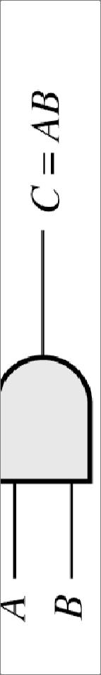
29 6.3 Combinatorial Logic Circuits Logic Gates Circuits that combine several logic- variable inputs to produce a logic-variable output. AND Gate AND operation = Logical Multiplication AB is 1 if and only if A and B are both 1. Truth table Table listing all the possible combinations of the input variables and the corresponding output values. 29
30 30
31 AA = A 1 = A A A0 0 = 0 AB = BA ( BC) ( AB) C ABC A = = 31
32 Logic Inverter It is the NOT operation on a logic variable. It is represented by placing a bar over the symbol. The bubble at the output is used to indicate inversion. OR Gate OR operation = logical addition A+B is 1 if A or B (or both) are 1. 32
33 A A = 0 A = A 33
34 34
35 ( A + B) + C = A + ( B + C) = A + B + C ( B C) AB AC A + = + A + 0 = A A + 1 = 1 A + A =1 1 A + A = A 35
36 Boolean Algebra Boolean algebra = Mathematical theory of logic variables Steps: 1) Produce a truth table 2) List all possible combinations 3) Show that both sides of the expression yield the same results. 36
37 Implementation of Boolean Expressions Implementation can be implemented by interconnection of AND gates, OR gates and inverters. Manipulate logic expression to find a simpler equivalent expression. F = ABC+ ABC+ CD+ CE+ DD+ DE = CA ( + D+ E) + DE 37
38 38
39 De Morgan s Laws ABC = A + B + C A+ B+ C= ABC If the variables in a logic expression are replaced by their inverses, 1) AND operation is replaced by OR 2) OR operation is replaced by AND, The entire expression is inverted, the resulting expression yields the same values. 39
40 De Morgan s Laws (Cont.) De Morgan s Laws provide an alternative way to write logic expressions. Any logic function can be implemented by using AND gates and inverters. Any logic function can be implemented by using OR gates and inverters. 40
41 Additional Logic Gates NAND = AND gate followed by an inverter NOR = OR gate followed by an inverter XOR (exclusive-or) Modulo-two addition (XOR yields 1 if A is 1 or if B is 1) Buffer Single input and produce the same output Equivalence gate = high output only if both inputs have the same value XOR followed by an inverter 41
42 42
43 Logical Sufficiency of NAND gates or of NOR gates Inverter = Inputs to a NAND gate tied together AND gate = NAND gate followed by an inverter Therefore, basic logic functions can be realized by using only NAND gates. 43
44 44
45 Logical Sufficiency of NAND gates or of NOR gates (Cont.) Similarly, basic logic functions can be realized by using only NOR gates. Are NAND gates or NOR gates more common? 45
46 46
47 6.4 Synthesis of Logic Circuits Methods to implement logic circuits given the specification for the output in terms of the inputs. Sum-of Products (SOP) Implementation Product terms that include all of the input variables (or their inverses) are called minterms. Finally, write an expression for the output variable as a logical sum of minterms. 47
48 Steps for SOP Implementation Form a product of all the input variables (or their inverses) for each row of the truth table for which the result is logic 1. The output is the sum of these products. 48
49 D= m( 0267,,, ) 49
50 50
51 Product of Sums (POS) Implementation Sum terms that include all of the input variables (or their inverses) are called maxterms. Finally, write an expression for the output variable as a logical product of maxterms. Steps for POS Implementation Form a sum of all the input variables (or their inverses) for each row of the truth th table for which the result is logic 0. The output is the product of these sums. 51
52 52
53 53
54 Decoders, Encoders, and Translators Many useful combinatorial circuits such as decoders, encoders and translators are available as integrated circuits. Examples: Calculator or Watch (BCD form) Calculator display needs a decoder to translate the four-bit binary-coded decimal words into seven-bit words (seven-segmentsegment display) 54
55 All segments except G are displayed for zero number so seven-bit word = four-bit binary-coded decimal word of 0000 (= number 0) 55
56 6.5 Minimization of Logic Circuits Logic functions can be expressed either as SOP or POS. Direct implementation may not yield the best circuit in terms of minimizing the number of gates required. Karnaugh Maps Graphical approach used to simplify logic expressions. Rectangular array of squares. Each square is one of minterms of logic variables 56
57 57
58 Karnaugh Maps (Cont.) The left and right (as well as top and bottom) edges are considered to be adjacent. Two squares with a common edge = 2-cube Four = 4-cube Also four squares in the map corners form a 4-cube 58
59 59
60 Spot the set of largest cube that cover the 1s in a Karnaugh map. Minimum SOP: 60
61 Conclusions Logic gates are the basic building blocks for complex digital systems. Complex combinatorial logic functions can be achieved simply pyby interconnecting NAND gates (or NOR gates). Logic gates can be interconnected to form flip-flops. A complex digital system consists of many gates, flip-flops, and registers. 61
62 Summary Digital it signals are more immune to the effect of noise than analog signals. Numerical data can be represented in decimal, binary, octal, hexadecimal, a or BCD. Logic variables take two values: 1 and 0. They can be combined by the AND, OR, and inverters. A truth table lists all combinations of input variables and the corresponding output. NAND (or NOR) gates are sufficient to realize any combinatorial logic functions. Any logic functions can be written as SOP or POS. Karnaugh maps is used to minimize the number of gates needed to implement a given logic function. 62
Odd-Prime Number Detector The table of minterms is represented. Table 13.1
 Odd-Prime Number Detector The table of minterms is represented. Table 13.1 Minterm A B C D E 1 0 0 0 0 1 3 0 0 0 1 1 5 0 0 1 0 1 7 0 0 1 1 1 11 0 1 0 1 1 13 0 1 1 0 1 17 1 0 0 0 1 19 1 0 0 1 1 23 1 0 1
CHAPTER 3 BASIC & COMBINATIONAL LOGIC CIRCUIT
 CHAPTER 3 BASIC & COMBINATIONAL LOGIC CIRCUIT CHAPTER CONTENTS 3.1 Introduction to Basic Gates 3.2 Analysing A Combinational Logic Circuit 3.3 Design A Combinational Logic Circuit From Boolean Expression
Number system: the system used to count discrete units is called number. Decimal system: the number system that contains 10 distinguished
 Number system: the system used to count discrete units is called number system Decimal system: the number system that contains 10 distinguished symbols that is 0-9 or digits is called decimal system. As
University of Technology
 University of Technology Lecturer: Dr. Sinan Majid Course Title: microprocessors 4 th year Lecture 7 & 8 NAND and XOR Implementations Combinational Design Procedure NAND-NAND & NOR-NOR Networks DeMorgan
Logic Design I (17.341) Fall Lecture Outline
 Fall Lecture Outline") Logic Design I (17.341) Fall 2011 Lecture Outline Class # 07 October 31, 2011 / November 07, 2011 Dohn Bowden 1 Today s Lecture Administrative Main Logic Topic Homework 2 Course Admin 3 Administrative
Logic Design I (17.341) Fall 2011 Lecture Outline Class # 07 October 31, 2011 / November 07, 2011 Dohn Bowden 1 Today s Lecture Administrative Main Logic Topic Homework 2 Course Admin 3 Administrative
Subject: Analog and Digital Electronics Code:15CS32
 Subject: Analog and Digital Electronics Code:15CS32 Syllabus: The Basic Gates : Review of Basic Logic gates, Positive and Negative Logic, Introduction to HDL. Combinational Logic Circuits:Sum-of-Products
Analysis procedure. To obtain the output Boolean functions from a logic diagram, proceed as follows:
 Combinational Logic Logic circuits for digital systems may be combinational or sequential. combinational circuit consists of input variables, logic gates, and output variables. 1 nalysis procedure To obtain
Name: Class: Date: 1. As more electronic systems have been designed using digital technology, devices have become smaller and less powerful.
 Name: Class: Date: DE Midterm Review 2 True/False Indicate whether the statement is true or false. 1. As more electronic systems have been designed using digital technology, devices have become smaller
CS302 Digital Logic Design Solved Objective Midterm Papers For Preparation of Midterm Exam
 CS302 Digital Logic Design Solved Objective Midterm Papers For Preparation of Midterm Exam MIDTERM EXAMINATION 2011 (October-November) Q-21 Draw function table of a half adder circuit? (2) Answer: - Page
Chapter 4: The Building Blocks: Binary Numbers, Boolean Logic, and Gates
 Chapter 4: The Building Blocks: Binary Numbers, Boolean Logic, and Gates Objectives In this chapter, you will learn about The binary numbering system Boolean logic and gates Building computer circuits
EECS 150 Homework 4 Solutions Fall 2008
 Problem 1: You have a 100 MHz clock, and need to generate 3 separate clocks at different frequencies: 20 MHz, 1kHz, and 1Hz. How many flip flops do you need to implement each clock if you use: a) a ring
Chapter 1: Digital logic
 Chapter 1: Digital logic I. Overview In PHYS 252, you learned the essentials of circuit analysis, including the concepts of impedance, amplification, feedback and frequency analysis. Most of the circuits
Digital. Design. R. Ananda Natarajan B C D
 Digital E A B C D 0 1 2 3 4 5 6 Design 7 8 9 10 11 12 13 14 15 Y R. Ananda Natarajan Digital Design Digital Design R. ANANDA NATARAJAN Professor Department of Electronics and Instrumentation Engineering
Positive and Negative Logic
 Course: B.Sc. Applied Physical Science (Computer Science) Year & Sem.: IInd Year, Sem - IIIrd Subject: Computer Science Paper No.: IX Paper Title: Computer System Architecture Lecture No.: 4 Lecture Title:
UNIT-IV Combinational Logic
 UNIT-IV Combinational Logic Introduction: The signals are usually represented by discrete bands of analog levels in digital electronic circuits or digital electronics instead of continuous ranges represented
(CSC-3501) Lecture 6 (31 Jan 2008) Seung-Jong Park (Jay) CSC S.J. Park. Announcement
 Lecture 6 (31 Jan 2008) Seung-Jong Park (Jay) CSC S.J. Park. Announcement") Seung-Jong Park (Jay) http://www.csc.lsu.edu/~sjpark Computer Architecture (CSC-3501) Lecture 6 (31 Jan 2008) 1 Announcement 2 1 Reminder A logic circuit is composed of: Inputs Outputs Functional specification
Seung-Jong Park (Jay) http://www.csc.lsu.edu/~sjpark Computer Architecture (CSC-3501) Lecture 6 (31 Jan 2008) 1 Announcement 2 1 Reminder A logic circuit is composed of: Inputs Outputs Functional specification
Digital Logic Circuits
 Digital Logic Circuits Let s look at the essential features of digital logic circuits, which are at the heart of digital computers. Learning Objectives Understand the concepts of analog and digital signals
COMBINATIONAL CIRCUIT
 Combinational circuit is a circuit in which we combine the different gates in the circuit, for example encoder, decoder, multiplexer and demultiplexer. Some of the characteristics of combinational circuits
DIGITAL ELECTRONICS QUESTION BANK
 DIGITAL ELECTRONICS QUESTION BANK Section A: 1. Which of the following are analog quantities, and which are digital? (a) Number of atoms in a simple of material (b) Altitude of an aircraft (c) Pressure
Module 4: Design and Analysis of Combinational Circuits 1. Module-4. Design and Analysis of Combinational Circuits
 1 Module-4 Design and Analysis of Combinational Circuits 4.1 Motivation: This topic develops the fundamental understanding and design of adder, substractor, code converter multiplexer, demultiplexer etc
Electronics. Digital Electronics
 Electronics Digital Electronics Introduction Unlike a linear, or analogue circuit which contains signals that are constantly changing from one value to another, such as amplitude or frequency, digital
Chapter 3 Digital Logic Structures
 Chapter 3 Digital Logic Structures Transistor: Building Block of Computers Microprocessors contain millions of transistors Intel Pentium 4 (2): 48 million IBM PowerPC 75FX (22): 38 million IBM/Apple PowerPC
UNIT-2: BOOLEAN EXPRESSIONS AND COMBINATIONAL LOGIC CIRCUITS
 UNIT-2: BOOLEAN EXPRESSIONS AND COMBINATIONAL LOGIC CIRCUITS STRUCTURE 2. Objectives 2. Introduction 2.2 Simplification of Boolean Expressions 2.2. Sum of Products 2.2.2 Product of Sums 2.2.3 Canonical
Dr. Nicola Nicolici COE/EE2DI4 Midterm Test #1 Oct 18, 2006
 COE/EE2DI4 Midterm Test #1 Fall 2006 Page 1 Dr. Nicola Nicolici COE/EE2DI4 Midterm Test #1 Oct 18, 2006 Instructions: This examination paper includes 10 pages and 20 multiple-choice questions starting
2 Logic Gates THE INVERTER. A logic gate is an electronic circuit which makes logic decisions. It has one output and one or more inputs.
 2 Logic Gates A logic gate is an electronic circuit which makes logic decisions. It has one output and one or more inputs. THE INVERTER The inverter (NOT circuit) performs the operation called inversion
EXPERIMENT NO 1 TRUTH TABLE (1)
") EPERIMENT NO AIM: To verify the Demorgan s theorems. APPARATUS REQUIRED: THEORY: Digital logic trainer and Patch cords. The digital signals are discrete in nature and can only assume one of the two values
EPERIMENT NO AIM: To verify the Demorgan s theorems. APPARATUS REQUIRED: THEORY: Digital logic trainer and Patch cords. The digital signals are discrete in nature and can only assume one of the two values
Digital Electronic Concepts
 Western Technical College 10662137 Digital Electronic Concepts Course Outcome Summary Course Information Description Career Cluster Instructional Level Total Credits 4.00 Total Hours 108.00 This course
Logic diagram: a graphical representation of a circuit
 LOGIC AND GATES Introduction to Logic (1) Logic diagram: a graphical representation of a circuit Each type of gate is represented by a specific graphical symbol Truth table: defines the function of a gate
LOGIC GATES AND LOGIC CIRCUITS A logic gate is an elementary building block of a Digital Circuit. Most logic gates have two inputs and one output.
 LOGIC GATES AND LOGIC CIRCUITS A logic gate is an elementary building block of a Digital Circuit. Most logic gates have two inputs and one output. At any given moment, every terminal is in one of the two
Gates and Circuits 1
 1 Gates and Circuits Chapter Goals Identify the basic gates and describe the behavior of each Describe how gates are implemented using transistors Combine basic gates into circuits Describe the behavior
M.Sc. (Computer Science) Master of Computer Application MS-03 / MCA-203 Course Curriculum for Digital Electronics
 Master of Computer Application MS-03 / MCA-203 Course Curriculum for Digital Electronics") M.Sc. (Computer Science) Master of Computer Application MS-03 / MCA-203 Course Curriculum for Digital Electronics 125001 Sr. No. Lesson Name Page No. 1. Introduction 3 2. Binary Algebra 13 3. Logic Gates
M.Sc. (Computer Science) Master of Computer Application MS-03 / MCA-203 Course Curriculum for Digital Electronics 125001 Sr. No. Lesson Name Page No. 1. Introduction 3 2. Binary Algebra 13 3. Logic Gates
TABLE 3-2 Truth Table for Code Converter Example
 997 by Prentice-Hall, Inc. Mano & Kime Upper Saddle River, New Jersey 7458 T-28 TABLE 3-2 Truth Table for Code Converter Example Decimal Digit Input BCD Output Excess-3 A B C D W Y Z 2 3 4 5 6 7 8 9 Truth
Course Overview. Course Overview
 Course Overview Where does this course fit into the Electrical Engineering curriculum? Page 5 Course Overview Where does this course fit into the Computer Engineering curriculum? Page 6 3 Course Content
Chapter 1 Binary Systems
 EEA051 - Digital Logic 數位邏輯 Chapter 1 Binary Systems 吳俊興高雄大學資訊工程學系 September 2005 Chapter 1. Binary Systems 1-1 Digital Systems 1-2 Binary Numbers 1-3 Number Base Conversions 1-4 Octal and Hexadecimal
Course Outline Cover Page
 College of Micronesia FSM P.O. Box 159 Kolonia, Pohnpei Course Outline Cover Page Digital Electronics I VEE 135 Course Title Department and Number Course Description: This course provides the students
Combinational Logic Circuits. Combinational Logic
 Combinational Logic Circuits The outputs of Combinational Logic Circuits are only determined by the logical function of their current input state, logic 0 or logic 1, at any given instant in time. The
CS302 - Digital Logic Design Glossary By
 CS302 - Digital Logic Design Glossary By ABEL : Advanced Boolean Expression Language; a software compiler language for SPLD programming; a type of hardware description language (HDL) Adder : A digital
EE292: Fundamentals of ECE
 EE292: Fundamentals of ECE Fall 2012 TTh 10:00-11:15 SEB 1242 Lecture 21 121113 http://www.ee.unlv.edu/~b1morris/ee292/ 2 Outline Chapter 7 - Logic Circuits Binary Number Representation Binary Arithmetic
SRV ENGINEERING COLLEGE SEMBODAI RUKMANI VARATHARAJAN ENGINEERING COLLEGE SEMBODAI
 SEMBODAI RUKMANI VARATHARAJAN ENGINEERING COLLEGE SEMBODAI 6489 (Approved By AICTE,Newdelhi Affiliated To ANNA UNIVERSITY::Chennai) CS 62 DIGITAL ELECTRONICS LAB (REGULATION-23) LAB MANUAL DEPARTMENT OF
Digital Applications (CETT 1415) Credit: 4 semester credit hours (3 hours lecture, 4 hours lab) Prerequisite: CETT 1403 & CETT 1405
 Credit: 4 semester credit hours (3 hours lecture, 4 hours lab) Prerequisite: CETT 1403 & CETT 1405") Digital Applications () Credit: 4 semester credit hours (3 hours lecture, 4 hours lab) Prerequisite: CETT 1403 & CETT 1405 Course Description This course covers digital techniques and numbering systems,
Digital Applications () Credit: 4 semester credit hours (3 hours lecture, 4 hours lab) Prerequisite: CETT 1403 & CETT 1405 Course Description This course covers digital techniques and numbering systems,
EEE 301 Digital Electronics
 EEE 301 Digital Electronics Lecture 1 Course Contents Introduction to number systems and codes. Analysis and synthesis of digital logic circuits: Basic logic functions, Boolean algebra,combinational logic
Digital Electronics Course Objectives
 Digital Electronics Course Objectives In this course, we learning is reported using Standards Referenced Reporting (SRR). SRR seeks to provide students with grades that are consistent, are accurate, and
Introduction to Digital Logic Missouri S&T University CPE 2210 Exam 1 Logistics
 Introduction to Digital Logic Missouri S&T University CPE 2210 Exam 1 Logistics Egemen K. Çetinkaya Egemen K. Çetinkaya Department of Electrical & Computer Engineering Missouri University of Science and
Encoders. Lecture 23 5
 -A decoder with enable input can function as a demultiplexer a circuit that receives information from a single line and directs it to one of 2 n possible output lines. The selection of a specific output
LOGIC DIAGRAM: HALF ADDER TRUTH TABLE: A B CARRY SUM. 2012/ODD/III/ECE/DE/LM Page No. 1
 LOGIC DIAGRAM: HALF ADDER TRUTH TABLE: A B CARRY SUM K-Map for SUM: K-Map for CARRY: SUM = A B + AB CARRY = AB 22/ODD/III/ECE/DE/LM Page No. EXPT NO: DATE : DESIGN OF ADDER AND SUBTRACTOR AIM: To design
Lecture 02: Digital Logic Review
 CENG 3420 Lecture 02: Digital Logic Review Bei Yu byu@cse.cuhk.edu.hk CENG3420 L02 Digital Logic. 1 Spring 2017 Review: Major Components of a Computer CENG3420 L02 Digital Logic. 2 Spring 2017 Review:
Digital Circuits Introduction
 Lecture #6 OUTLINE Logic inary representations Combinatorial logic circuits Chap 7-7.5 Reading EE4 Summer 25: Lecture 6 Instructor: Octavian lorescu Digital Circuits Introduction nalog: signal amplitude
NUMBER SYSTEM AND CODES
 NUMBER SYSTEM AND CODES INTRODUCTION:- The term digital refers to a process that is achieved by using discrete unit. In number system there are different symbols and each symbol has an absolute value and
LIST OF EXPERIMENTS. KCTCET/ /Odd/3rd/ETE/CSE/LM
 LIST OF EXPERIMENTS. Study of logic gates. 2. Design and implementation of adders and subtractors using logic gates. 3. Design and implementation of code converters using logic gates. 4. Design and implementation
Digital Electronics 8. Multiplexer & Demultiplexer
 1 Module -8 Multiplexers and Demultiplexers 1 Introduction 2 Principles of Multiplexing and Demultiplexing 3 Multiplexer 3.1 Types of multiplexer 3.2 A 2 to 1 multiplexer 3.3 A 4 to 1 multiplexer 3.4 Multiplex
BOOLEAN ALGEBRA AND LOGIC FAMILIES
 C H A P T E R 7 Learning Objectives Unique Feature of Boolean Algebra Laws of Boolean Algebra Equivalent Switching Circuits DeMorgan s Theorem s The Sum-of-Products (SOP) Form The Standard SOP Form The
Combinational Logic Design CH002
 Combinational Logic Design CH002 Figure 2.1 Circuit as a black box with inputs, outputs, and specifications Figure 2.2 Elements and nodes Figure 2.3 Combinational logic circuit Figure 2.4 Two OR implementations
Department of Electronics and Communication Engineering
 Department of Electronics and Communication Engineering Sub Code/Name: BEC3L2- DIGITAL ELECTRONICS LAB Name Reg No Branch Year & Semester : : : : LIST OF EXPERIMENTS Sl No Experiments Page No Study of
Approximate Hybrid Equivalent Circuits. Again, the impedance looking into the output terminals is infinite so that. conductance is zero.
 Again, the impedance looking into the output terminals is infinite so that conductance is zero. Hence, the four h-parameters of an ideal transistor connected in CE transistor are The hybrid equivalent
IES Digital Mock Test
 . The circuit given below work as IES Digital Mock Test - 4 Logic A B C x y z (a) Binary to Gray code converter (c) Binary to ECESS- converter (b) Gray code to Binary converter (d) ECESS- To Gray code
Objective Questions. (a) Light (b) Temperature (c) Sound (d) all of these
 Light (b) Temperature (c) Sound (d) all of these") Objective Questions Module 1: Introduction 1. Which of the following is an analog quantity? (a) Light (b) Temperature (c) Sound (d) all of these 2. Which of the following is a digital quantity? (a) Electrical
Objective Questions Module 1: Introduction 1. Which of the following is an analog quantity? (a) Light (b) Temperature (c) Sound (d) all of these 2. Which of the following is a digital quantity? (a) Electrical
1.) If a 3 input NOR gate has eight input possibilities, how many of those possibilities result in a HIGH output? (a.) 1 (b.) 2 (c.) 3 (d.) 7 (e.
 If a 3 input NOR gate has eight input possibilities, how many of those possibilities result in a HIGH output? (a.) 1 (b.) 2 (c.) 3 (d.) 7 (e.") Name: Multiple Choice 1.) If a 3 input NOR gate has eight input possibilities, how many of those possibilities result in a HIGH output? (a.) 1 (b.) 2 (c.) 3 (d.) 7 (e.) 8 2.) The output of an OR gate with
Name: Multiple Choice 1.) If a 3 input NOR gate has eight input possibilities, how many of those possibilities result in a HIGH output? (a.) 1 (b.) 2 (c.) 3 (d.) 7 (e.) 8 2.) The output of an OR gate with
Lecture 15 Analysis of Combinational Circuits
 Lecture 15 Analysis of Combinational Circuits Designing Combinational Logic Circuits A logic circuit having 3 inputs, A, B, C will have its output HIGH only when a majority of the inputs are HIGH. Step
Unit 3. Logic Design
 EE 2: Digital Logic Circuit Design Dr Radwan E Abdel-Aal, COE Logic and Computer Design Fundamentals Unit 3 Chapter Combinational 3 Combinational Logic Logic Design - Introduction to Analysis & Design
Combinational Logic. Combinational Logic Design Process, Three State Buffers, Decoders, Multiplexers, Encoders, Demultiplexers, Other Considerations
 Combinational Logic Combinational Logic Design Process, Three State Buffers, Decoders, Multiplexers, Encoders, Demultiplexers, Other Considerations Copyright (c) 2012 Sean Key Combinational Logic Design
Function Table of an Odd-Parity Generator Circuit
 Implementation of an Odd-Parity Generator Circuit The first step in implementing any circuit is to represent its operation in terms of a Truth or Function table. The function table for an 8-bit data as
Logic Circuit Design
 Logic Circuit Design we have studied Truth Tables Logic gates Logic algebra K-maps 1 All these are tools Tools Truth Tables Logic gates Logic algebra K-maps 2 All these are tools Tools Truth Tables Logic
Unit 1 Foundations in Electronics - Lesson 1.1 Introduction to Electronics Standards Essential Question Enduring Understandings
 Course: DIGITAL ELECTRONICS- PROJECT LEAD THE WAY (DE-PLTW) Year: 2017-2018 Teacher: Mr. Christopher Reynolds/ Mr. Kenneth Rice Unit 1 Foundations in Electronics - Lesson 1.1 Introduction to Electronics
UNIT III. Designing Combinatorial Circuits. Adders
 UNIT III Designing Combinatorial Circuits The design of a combinational circuit starts from the verbal outline of the problem and ends with a logic circuit diagram or a set of Boolean functions from which
Digital Applications (CETT 1415) Credit: 4 semester credit hours (3 hours lecture, 4 hours lab) Prerequisite: CETT 1403 & CETT 1405
 Credit: 4 semester credit hours (3 hours lecture, 4 hours lab) Prerequisite: CETT 1403 & CETT 1405") Digital Applications (CETT 1415) Credit: 4 semester credit hours (3 hours lecture, 4 hours lab) Prerequisite: CETT 1403 & CETT 1405 Course Description This course covers digital techniques and numbering
Digital Applications (CETT 1415) Credit: 4 semester credit hours (3 hours lecture, 4 hours lab) Prerequisite: CETT 1403 & CETT 1405 Course Description This course covers digital techniques and numbering
Paper No. Name of the Paper Theory marks Practical marks Periods per week Semester-I I Semiconductor
 Swami Ramanand Teerth Marathwada University, Nanded B. Sc. First Year Electronics Syllabus Semester system (To be implemented from Academic Year 2009-10) Name of the Theory marks Practical marks Periods
DIGITAL CIRCUITS AND SYSTEMS ASSIGNMENTS 1 SOLUTIONS
 DIGITAL CIRCUITS AND SYSTEMS ASSIGNMENTS 1 SOLUTIONS 1. Analog signal varies continuously between two amplitudes over the given interval of time. Between these limits of amplitude and time, the signal
Gates and and Circuits
 Chapter 4 Gates and Circuits Chapter Goals Identify the basic gates and describe the behavior of each Describe how gates are implemented using transistors Combine basic gates into circuits Describe the
DESIGN OF 4 BIT BINARY ARITHMETIC CIRCUIT USING 1 S COMPLEMENT METHOD
 e-issn 2455 1392 Volume 2 Issue 4, April 2016 pp. 176-187 Scientific Journal Impact Factor : 3.468 http://www.ijcter.com DESIGN OF 4 BIT BINARY ARITHMETIC CIRCUIT USING 1 S COMPLEMENT METHOD Dhrubojyoti
ECE380 Digital Logic
 ECE38 Digital Logic Optimized Implementation of Logic Functions: Karnaugh Maps and Minimum Sum-of-Product Forms Dr. D. J. Jackson Lecture 7- Karnaugh map The key to finding a minimum cost SOP or POS form
MAHARASHTRA STATE BOARD OF TECHNICAL EDUCATION (Autonomous) (ISO/IEC Certified) SUMMER-16 EXAMINATION Model Answer
 (ISO/IEC Certified) SUMMER-16 EXAMINATION Model Answer") Important Instructions to examiners: 1) The answers should be examined by key words and not as word-to-word as given in the model answer scheme. 2) The model answer and the answer written by candidate
Important Instructions to examiners: 1) The answers should be examined by key words and not as word-to-word as given in the model answer scheme. 2) The model answer and the answer written by candidate
This Figure here illustrates the operation for a 2-input OR gate for all four possible input combinations.
 Course: B.Sc. Applied Physical Science (Computer Science) Year & Sem.: IInd Year, Sem - IIIrd Subject: Computer Science Paper No.: IX Paper Title: Computer System Architecture Lecture No.: 5 Lecture Title:
EE40 Lecture 35. Prof. Chang-Hasnain. 12/5/07 Reading: Ch 7, Supplementary Reader
 EE4 Lecture 35 2/5/7 Reading: Ch 7, Supplementary Reader EE4 all 26 Slide Week 5 OUTLINE Need for Input Controlled Pull-Up CMOS Inverter nalysis CMOS Voltage Transfer Characteristic Combinatorial logic
Combinational Circuits: Multiplexers, Decoders, Programmable Logic Devices
 Combinational Circuits: Multiplexers, Decoders, Programmable Logic Devices Lecture 5 Doru Todinca Textbook This chapter is based on the book [RothKinney]: Charles H. Roth, Larry L. Kinney, Fundamentals
COMPUTER ORGANIZATION & ARCHITECTURE DIGITAL LOGIC CSCD211- DEPARTMENT OF COMPUTER SCIENCE, UNIVERSITY OF GHANA
 COMPUTER ORGANIZATION & ARCHITECTURE DIGITAL LOGIC LOGIC Logic is a branch of math that tries to look at problems in terms of being either true or false. It will use a set of statements to derive new true
INTRODUCTION TO DIGITAL CONCEPT
 COURSE / CODE DIGITAL SYSTEM FUNDAMENTALS (ECE 421) DIGITAL ELECTRONICS FUNDAMENTAL (ECE 422) INTRODUCTION TO DIGITAL CONCEPT Digital and Analog Quantities Digital relates to data in the form of digits,
1. The decimal number 62 is represented in hexadecimal (base 16) and binary (base 2) respectively as
 and binary (base 2) respectively as") BioE 1310 - Review 5 - Digital 1/16/2017 Instructions: On the Answer Sheet, enter your 2-digit ID number (with a leading 0 if needed) in the boxes of the ID section. Fill in the corresponding numbered
BioE 1310 - Review 5 - Digital 1/16/2017 Instructions: On the Answer Sheet, enter your 2-digit ID number (with a leading 0 if needed) in the boxes of the ID section. Fill in the corresponding numbered
ELECTRONIC CIRCUITS. Time: Three Hours Maximum Marks: 100
 EC 40 MODEL TEST PAPER - 1 ELECTRONIC CIRCUITS Time: Three Hours Maximum Marks: 100 Answer five questions, taking ANY TWO from Group A, any two from Group B and all from Group C. All parts of a question
B.C.A 2017 DIGITAL ELECTRONICS BCA104T MODULE SPECIFICATION SHEET. Course Outline
 Course Outline B.C.A 2017 DIGITAL ELECTRONICS BCA104T MODULE SPECIFICATION SHEET The purpose of the course is to teach principles of digital electronics. This course covers varieties of topics including
Introduction (concepts and definitions)
") Objectives: Introduction (digital system design concepts and definitions). Advantages and drawbacks of digital techniques compared with analog. Digital Abstraction. Synchronous and Asynchronous Systems.
Objectives: Introduction (digital system design concepts and definitions). Advantages and drawbacks of digital techniques compared with analog. Digital Abstraction. Synchronous and Asynchronous Systems.
4:Combinational logic circuits. 3 July
 4:Combinational logic circuits 3 July 2014 1 overview What is combinational logic circuit? Examples of combinational logic circuits Binary-adder Binary-subtractor Binary-multiplier Decoders Multiplexers
JEFFERSON COLLEGE COURSE SYLLABUS ETC255 INTRODUCTION TO DIGITAL CIRCUITS. 6 Credit Hours. Prepared by: Dennis Eimer
 JEFFERSON COLLEGE COURSE SYLLABUS ETC255 INTRODUCTION TO DIGITAL CIRCUITS 6 Credit Hours Prepared by: Dennis Eimer Revised Date: August, 2007 By Dennis Eimer Division of Technology Dr. John Keck, Dean
Lecture 2: Digital Logic Basis
 Lecture 2: Digital Logic Basis Xufeng Kou School of Information Science and Technology ShanghaiTech University 1 Outline Truth Table Basic Logic Operation and Gates Logic Circuits NOR Gates and NAND Gates
Multiple input gates. The AND gate
 Multiple input gates Inverters and buffers exhaust the possibilities for single-input gate circuits. What more can be done with a single logic signal but to buffer it or invert it? To explore more logic
DIGITAL ELECTRONICS. Methods & diagrams : 1 Graph plotting : - Tables & analysis : - Questions & discussion : 6 Performance : 3
 DIGITAL ELECTRONICS Marking scheme : Methods & diagrams : 1 Graph plotting : - Tables & analysis : - Questions & discussion : 6 Performance : 3 Aim: This experiment will investigate the function of the
Introduction. BME208 Logic Circuits Yalçın İŞLER
 Introduction BME208 Logic Circuits Yalçın İŞLER islerya@yahoo.com http://me.islerya.com 1 Lecture Three hours a week (three credits) No other sections, please register this section Tuesday: 09:30 12:15
Fan in: The number of inputs of a logic gate can handle.
 Subject Code: 17333 Model Answer Page 1/ 29 Important Instructions to examiners: 1) The answers should be examined by key words and not as word-to-word as given in the model answer scheme. 2) The model
Digital Electronics. A. I can list five basic safety rules for electronics. B. I can properly display large and small numbers in proper notation,
 St. Michael Albertville High School Teacher: Scott Danielson September 2016 Content Skills Learning Targets Standards Assessment Resources & Technology CEQ: WHAT MAKES DIGITAL ELECTRONICS SO IMPORTANT
Laboratory Manual CS (P) Digital Systems Lab
 Digital Systems Lab") Laboratory Manual CS 09 408 (P) Digital Systems Lab INDEX CYCLE I A. Familiarization of digital ICs and digital IC trainer kit 1 Verification of truth tables B. Study of combinational circuits 2. Verification
Laboratory Manual CS 09 408 (P) Digital Systems Lab INDEX CYCLE I A. Familiarization of digital ICs and digital IC trainer kit 1 Verification of truth tables B. Study of combinational circuits 2. Verification
DELD UNIT 3. Question Option A Option B Option C Option D Correct Option A B C
 Class : S.E.Comp Matoshri College of Engineering and Research Center Nasik Department of Computer Engineering Digital Elecronics and Logic Design (DELD) UNIT - III Subject : DELD Sr. No. Question Option
SYNTHESIS OF COMBINATIONAL CIRCUITS
 HPTER 6 SYNTHESIS O OMINTIONL IRUITS 6.1 Introduction oolean functions can be expressed in the forms of sum-of-products and productof-sums. These expressions can also be minimized using algebraic manipulations
Chapter 8. Chapter 9. Chapter 6. Chapter 10. Chapter 11. Chapter 7
 5.5 Series and Parallel Combinations of 246 Complex Impedances 5.6 Steady-State AC Node-Voltage 247 Analysis 5.7 AC Power Calculations 256 5.8 Using Power Triangles 258 5.9 Power-Factor Correction 261
Electronic Components And Circuit Analysis
 Theory /Practical Theory Semester /Annual Semester Semester No. I II Swami Ramanand Teerth Marathwada University, Nanded Syllabus B. Sc. First Year ELECTRONICS Semester System (MCQ Pattern) (To Be Implemented
Analog to digital and digital to analog converters
 Analog to digital and digital to analog converters A/D converter D/A converter ADC DAC ad da Number bases Decimal, base, numbers - 9 Binary, base, numbers and Oktal, base 8, numbers - 7 Hexadecimal, base
Veer Narmad South Gujarat University, Surat
 Unit I: Passive circuit elements (With effect from June 2017) Syllabus for: F Y B Sc (Electronics) Semester- 1 PAPER I: Basic Electrical Circuits Resistors, resistor types, power ratings, resistor colour
ELECTRONICS ADVANCED SUPPLEMENTARY LEVEL
 ELECTRONICS ADVANCED SUPPLEMENTARY LEVEL AIMS The general aims of the subject are : 1. to foster an interest in and an enjoyment of electronics as a practical and intellectual discipline; 2. to develop
OBJECTIVE TYPE QUESTIONS FOR PRACTICAL EXAMINATION Subject : Electronics-I ( EC 112)
") OBJECTIVE TYPE QUESTIONS FOR PRACTICAL EXAMINATION Subject : Electronics-I ( EC 112) 1. Which mathematical notation specifies the condition of periodicity for a continuous time signal? a. x(t) = x( t +T)
OBJECTIVE TYPE QUESTIONS FOR PRACTICAL EXAMINATION Subject : Electronics-I ( EC 112) 1. Which mathematical notation specifies the condition of periodicity for a continuous time signal? a. x(t) = x( t +T)
Combinational logic. ! Regular logic: multiplexers, decoders, LUTs and FPGAs. ! Switches, basic logic and truth tables, logic functions
 Combinational logic! Switches, basic logic and truth tables, logic functions! Algebraic expressions to gates! Mapping to different gates! Discrete logic gate components (used in labs and 2)! Canonical
Lab Report: Digital Logic
 Lab Report: Digital Logic Introduction The aim of the Digital Logic Lab was to construct a simple 4-bit Arithmetic Logic Unit (ALU) in order to demonstrate methods of using Boolean Algebra to manipulate
Syllabus: Digital Electronics (DE) (Project Lead The Way)
 (Project Lead The Way)") Course Overview: Digital electronics and micro computers. This is a course in applied logic that encompasses the application of electronic circuits and devices. Computer simulation software is used to
Course Overview: Digital electronics and micro computers. This is a course in applied logic that encompasses the application of electronic circuits and devices. Computer simulation software is used to