Logic Circuit Design
|
|
|
- Claude Bates
- 6 years ago
- Views:
Transcription
1 Logic Circuit Design
2 we have studied Truth Tables Logic gates Logic algebra K-maps 1
3 All these are tools Tools Truth Tables Logic gates Logic algebra K-maps 2
4 All these are tools Tools Truth Tables Logic gates Logic algebra K-maps To design digital logic circuits 3
5 Today we will learn Truth Tables Logic gates Logic algebra K-maps To set-up and implement logic circuit problems (Logic Circuit Design) 4
6 4-Questions for a design problem 1. What do we need to know for a design problem? Specifications (inputs, outputs, function) 2. Can we set-up a truth table? Truth tables determine the function of the problem 3. Can we simplify? - Use K- maps or logic algebra 4. Can we implement the result with a circuit? - Use gates 5
7 Steps to Design a Logic Circuit Given a word problem 6
8 Steps to Design a Logic Circuit Given a word problem Create Truth Table 7
9 Steps to Design a Logic Circuit Given a word problem Create Truth Table Derive Output Expression(s) 8
10 Steps to Design a Logic Circuit Given a word problem Logic Circuit Create Truth Table Derive Output Expression(s) 9
11 Steps to Design a Logic Circuit Given a word problem Logic Circuit Create Truth Table Derive Output Expression(s) Simplify 10
12 Steps to Design a Logic Circuit Given a word problem Logic Circuit Create Truth Table Derive Output Expression(s) Simplify Implement (Gates) 11
13 Algorithm: Logic circuit design 1. From the specifications of the problem: Determine the required number of inputs and outputs. Assign a letter symbol to each 2. Derive the truth table 3. Obtain the Boolean expressions for each output as a function of the input variables 4. Simplify all the output equations 5. Draw the logic diagram 6. Verify the correctness of the design 12
14 Algorithm: Logic circuit design S y n t h e s I s 1. From the specifications of the problem: Determine the required number of inputs and outputs. Assign a letter symbol to each 2. Derive the truth table 3. Obtain the Boolean expressions for each output as a function of the input variables 4. Simplify all the output equations 5. Draw the logic diagram Implementation 6. Verify the correctness of the design 13
15 Example: Design problem Design a digital logic circuit with three inputs and one output. The output of the logic circuit, must be logic one(1)2 when the binary value of the inputs is less than three(011)2 and zero(0)2 otherwise. 14
16 1. Inputs/Outputs Inputs = 3 Output = 1 15
17 Inputs/Outputs/Truth table Inputs = 3 Output = 1 Design a digital logic circuit with three inputs and one output. The output of the logic circuit, must be logic one(1)2 when the binary value of the inputs is less than three(011)2 and zero(0)2 otherwise. A B C X
18 2. Function - Truth table A B C X Design a digital logic circuit with three inputs and one output. The output of the logic circuit, must be logic one(1)2 when the binary value of the inputs is less than three(011)2 and zero(0)2 otherwise
19 Terms of the output expression A B C X ABC ABC ABC 18
20 3. Output Boolean expression _ X = ABC + ABC + ABC A B C X ABC ABC ABC 19
21 4. Simplification K-Map AB C ABC ABC ABC 20
22 4. Simplification K-Map AB C ABC ABC ABC 10 X = A B + A C 21
23 5. Implementation: Simplified logic circuit A = 1 B = 0 C = 1 X = A B + A C 22

24 6. Verification A = 1 B = 0 C =
25 Logic diagram-vhdl editor Not in the Exam 26
26 Design: 1-bit Binary Comparator Compare two binary digits New Example 29

27 Design: 1-bit Comparator A 1-bit binary comparator compares the values of two bits and produces the proper result. A B A, B = 0 or 1 30
28 Design: 1-bit Comparator An 1-bit binary comparator compares the values of two bits and produces the proper result. What is the proper result? 31
29 1-bit Comparator There are three cases: 1. The two bits are equal 2. One bit has a greater value that the other 3. One bit has a smaller value than the other 32
30 Inputs/Outputs/Function Inputs:? Outputs:? Function: Comparator 33
31 Inputs/Outputs/Function Inputs: 2 Outputs: 3 Function: Comparator 34
32 Label the Input/Output A B? E (A = B) L (A < B) G (A > B) 35
33 Truth table? A B A = B A < B A > B E L G 36
34 Truth table A B A = B A < B A > B E L G 37
35 Truth table E L G A B A = B A < B A > B
36 We have 3 output equations E L G A B A = B A < B A > B E = A B + AB L = A B G = AB 39
 E = A B + AB L = A B G")
37 1-bit Comparator (Logic Circuit) E = A B + AB L = A B G = AB 40
38 VHDL: Logic circuit E = A B + AB = A XNOR B G = AB L = A B 41
39 VHDL Not in the Exam 42
40 Another design example Design a BCD-to-7 Segment Display converter New Example 43
41 Input, outputs(s), function? BCD 7SD (7-Segment-Display) 44
42 BCD BCD = Binary Coded Decimal A B C D

43 7SD 46


44 7SD 47


45 BCD to 7SD converter A B C D BCD to 7-segment decoder 48

46 49


47 Simplify 50
48 K-maps 51

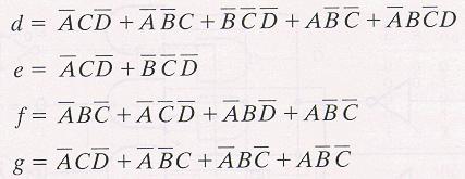
49 Simplified equations 52
50 Implement VHDL 53

 54")
51 Implement using a chip (7446) 54
52 Design a binary converter Design a binary logic circuit, to convert a 3-bit binary number to it s 2 s complement. a 3-bit binary converter 2 s complement(a) New Example 55
53 Design a binary converter Design a binary logic circuit, to convert a 3-bit binary number to it s 2 s complement. How many inputs and outputs? Inputs = 3 Outputs =? Need to set up the truth table. 56
54 Design a binary converter Design a binary logic circuit, to convert a 3-bit binary number to it s 2 s complement. Binary ABC s complement XYZ 57
55 Design a binary converter Design a binary logic circuit, to convert a 3-bit binary number to it s 2 s complement. Binary 1 s complement 2 s complement ABC XYZ
56 Design a binary converter Design a binary logic circuit, to convert a 3-bit binary number to it s 2 s complement. Binary 1 s complement 2 s complement ABC XYZ XYZW The X=1 is like an overflow Write the output equations Simplify Implement 5 minutes 59
57 2 s Complement + Logic Expressions Decimal A B C X Y Z W
58 61

59 Solution 62
Odd-Prime Number Detector The table of minterms is represented. Table 13.1
 Odd-Prime Number Detector The table of minterms is represented. Table 13.1 Minterm A B C D E 1 0 0 0 0 1 3 0 0 0 1 1 5 0 0 1 0 1 7 0 0 1 1 1 11 0 1 0 1 1 13 0 1 1 0 1 17 1 0 0 0 1 19 1 0 0 1 1 23 1 0 1
Number system: the system used to count discrete units is called number. Decimal system: the number system that contains 10 distinguished
 Number system: the system used to count discrete units is called number system Decimal system: the number system that contains 10 distinguished symbols that is 0-9 or digits is called decimal system. As
2 Logic Gates THE INVERTER. A logic gate is an electronic circuit which makes logic decisions. It has one output and one or more inputs.
 2 Logic Gates A logic gate is an electronic circuit which makes logic decisions. It has one output and one or more inputs. THE INVERTER The inverter (NOT circuit) performs the operation called inversion
Combinational Logic. Rab Nawaz Khan Jadoon DCS. Lecturer COMSATS Lahore Pakistan. Department of Computer Science
 Combinational Logic Rab Nawaz Khan Jadoon DCS COMSATS Institute of Information Technology Lecturer COMSATS Lahore Pakistan Digital Logic and Computer Design 2 Combinational logic A combinational circuit
University of Technology
 University of Technology Lecturer: Dr. Sinan Majid Course Title: microprocessors 4 th year Lecture 7 & 8 NAND and XOR Implementations Combinational Design Procedure NAND-NAND & NOR-NOR Networks DeMorgan
Lecture 15 Analysis of Combinational Circuits
 Lecture 15 Analysis of Combinational Circuits Designing Combinational Logic Circuits A logic circuit having 3 inputs, A, B, C will have its output HIGH only when a majority of the inputs are HIGH. Step
LOGIC GATES AND LOGIC CIRCUITS A logic gate is an elementary building block of a Digital Circuit. Most logic gates have two inputs and one output.
 LOGIC GATES AND LOGIC CIRCUITS A logic gate is an elementary building block of a Digital Circuit. Most logic gates have two inputs and one output. At any given moment, every terminal is in one of the two
EMT1250 LABORATORY EXPERIMENT. EXPERIMENT # 4: Combinational Logic Circuits. Name: Date:
 EXPERIMENT # 4: Combinational Logic Circuits Name: Date: Equipment/Parts Needed: 5V DC Power Supply Digital Trainer (Logic Probe) Breadboard DIP Switch 7400 NAND gate 7402 NOR gate 7404 Inverter 7408 AND
Function Table of an Odd-Parity Generator Circuit
 Implementation of an Odd-Parity Generator Circuit The first step in implementing any circuit is to represent its operation in terms of a Truth or Function table. The function table for an 8-bit data as
Dr. Nicola Nicolici COE/EE2DI4 Midterm Test #1 Oct 18, 2006
 COE/EE2DI4 Midterm Test #1 Fall 2006 Page 1 Dr. Nicola Nicolici COE/EE2DI4 Midterm Test #1 Oct 18, 2006 Instructions: This examination paper includes 10 pages and 20 multiple-choice questions starting
Digital Logic Design ELCT 201
 Faculty of Information Engineering and Technology Dr. Haitham Omran and Dr. Wassim Alexan Digital Logic Design ELCT 201 Winter 2017 Midterm Exam Second Chance Please tick the box of your major: IET MET
Logic Design I (17.341) Fall Lecture Outline
 Fall Lecture Outline") Logic Design I (17.341) Fall 2011 Lecture Outline Class # 07 October 31, 2011 / November 07, 2011 Dohn Bowden 1 Today s Lecture Administrative Main Logic Topic Homework 2 Course Admin 3 Administrative
Logic Design I (17.341) Fall 2011 Lecture Outline Class # 07 October 31, 2011 / November 07, 2011 Dohn Bowden 1 Today s Lecture Administrative Main Logic Topic Homework 2 Course Admin 3 Administrative
CHAPTER 3 BASIC & COMBINATIONAL LOGIC CIRCUIT
 CHAPTER 3 BASIC & COMBINATIONAL LOGIC CIRCUIT CHAPTER CONTENTS 3.1 Introduction to Basic Gates 3.2 Analysing A Combinational Logic Circuit 3.3 Design A Combinational Logic Circuit From Boolean Expression
Exercise 2: OR/NOR Logic Functions
 Exercise 2: OR/NOR Logic Functions EXERCISE OBJECTIVE When you have completed this exercise, you will be able to determine the operation of an OR and a NOR logic gate. You will verify your results by generating
Digital Electronics 8. Multiplexer & Demultiplexer
 1 Module -8 Multiplexers and Demultiplexers 1 Introduction 2 Principles of Multiplexing and Demultiplexing 3 Multiplexer 3.1 Types of multiplexer 3.2 A 2 to 1 multiplexer 3.3 A 4 to 1 multiplexer 3.4 Multiplex
Asst. Prof. Thavatchai Tayjasanant, PhD. Power System Research Lab 12 th Floor, Building 4 Tel: (02)
") 2145230 Aircraft Electricity and Electronics Asst. Prof. Thavatchai Tayjasanant, PhD Email: taytaycu@gmail.com aycu@g a co Power System Research Lab 12 th Floor, Building 4 Tel: (02) 218-6527 1 Chapter
2145230 Aircraft Electricity and Electronics Asst. Prof. Thavatchai Tayjasanant, PhD Email: taytaycu@gmail.com aycu@g a co Power System Research Lab 12 th Floor, Building 4 Tel: (02) 218-6527 1 Chapter
 Class Subject Code Subject Prepared By Lesson Plan for Time: Lesson. No 1.CONTENT LIST: Introduction to UnitII 2. SKILLS ADDRESSED: Learning I year, 02 sem CS6201 Digital Principles & System Design S.Seedhanadevi
Encoders. Lecture 23 5
 -A decoder with enable input can function as a demultiplexer a circuit that receives information from a single line and directs it to one of 2 n possible output lines. The selection of a specific output
Digital Circuits II Lecture 6. Lab Demonstration 3 Using Altera Quartus II to Determine Simplified Equations & Entering Truth Table into VHDL
 Digital Circuits II Lecture 6 Lab Demonstration 3 Using Altera Quartus II to Determine Simplified Equations & Entering Truth Table into VHDL References (Text Book): 1) Digital Electronics, 9 th editon,
Digital Electronic Concepts
 Western Technical College 10662137 Digital Electronic Concepts Course Outcome Summary Course Information Description Career Cluster Instructional Level Total Credits 4.00 Total Hours 108.00 This course
Chapter 4: The Building Blocks: Binary Numbers, Boolean Logic, and Gates
 Chapter 4: The Building Blocks: Binary Numbers, Boolean Logic, and Gates Objectives In this chapter, you will learn about The binary numbering system Boolean logic and gates Building computer circuits
4:Combinational logic circuits. 3 July
 4:Combinational logic circuits 3 July 2014 1 overview What is combinational logic circuit? Examples of combinational logic circuits Binary-adder Binary-subtractor Binary-multiplier Decoders Multiplexers
Digital Applications (CETT 1415) Credit: 4 semester credit hours (3 hours lecture, 4 hours lab) Prerequisite: CETT 1403 & CETT 1405
 Credit: 4 semester credit hours (3 hours lecture, 4 hours lab) Prerequisite: CETT 1403 & CETT 1405") Digital Applications () Credit: 4 semester credit hours (3 hours lecture, 4 hours lab) Prerequisite: CETT 1403 & CETT 1405 Course Description This course covers digital techniques and numbering systems,
Digital Applications () Credit: 4 semester credit hours (3 hours lecture, 4 hours lab) Prerequisite: CETT 1403 & CETT 1405 Course Description This course covers digital techniques and numbering systems,
Combinational Logic Circuits. Combinational Logic
 Combinational Logic Circuits The outputs of Combinational Logic Circuits are only determined by the logical function of their current input state, logic 0 or logic 1, at any given instant in time. The
Experiment # 4. Binary Addition & Subtraction. Eng. Waleed Y. Mousa
 Experiment # 4 Binary Addition & Subtraction Eng. Waleed Y. Mousa 1. Objectives: 1. To study adder and subtractor circuits using logic gates. 2. To construct and test various adders and subtractor circuits.
COMBINATIONAL CIRCUIT
 Combinational circuit is a circuit in which we combine the different gates in the circuit, for example encoder, decoder, multiplexer and demultiplexer. Some of the characteristics of combinational circuits
CS302 Digital Logic Design Solved Objective Midterm Papers For Preparation of Midterm Exam
 CS302 Digital Logic Design Solved Objective Midterm Papers For Preparation of Midterm Exam MIDTERM EXAMINATION 2011 (October-November) Q-21 Draw function table of a half adder circuit? (2) Answer: - Page
DIGITAL ELECTRONICS QUESTION BANK
 DIGITAL ELECTRONICS QUESTION BANK Section A: 1. Which of the following are analog quantities, and which are digital? (a) Number of atoms in a simple of material (b) Altitude of an aircraft (c) Pressure
2 Building Blocks. There is often the need to compare two binary values.
 2 Building Blocks 2.1 Comparators There is often the need to compare two binary values. This is done using a comparator. A comparator determines whether binary values A and B are: 1. A = B 2. A < B 3.
Unit 3. Logic Design
 EE 2: Digital Logic Circuit Design Dr Radwan E Abdel-Aal, COE Logic and Computer Design Fundamentals Unit 3 Chapter Combinational 3 Combinational Logic Logic Design - Introduction to Analysis & Design
TABLE 3-2 Truth Table for Code Converter Example
 997 by Prentice-Hall, Inc. Mano & Kime Upper Saddle River, New Jersey 7458 T-28 TABLE 3-2 Truth Table for Code Converter Example Decimal Digit Input BCD Output Excess-3 A B C D W Y Z 2 3 4 5 6 7 8 9 Truth
Digital Applications (CETT 1415) Credit: 4 semester credit hours (3 hours lecture, 4 hours lab) Prerequisite: CETT 1403 & CETT 1405
 Credit: 4 semester credit hours (3 hours lecture, 4 hours lab) Prerequisite: CETT 1403 & CETT 1405") Digital Applications (CETT 1415) Credit: 4 semester credit hours (3 hours lecture, 4 hours lab) Prerequisite: CETT 1403 & CETT 1405 Course Description This course covers digital techniques and numbering
Digital Applications (CETT 1415) Credit: 4 semester credit hours (3 hours lecture, 4 hours lab) Prerequisite: CETT 1403 & CETT 1405 Course Description This course covers digital techniques and numbering
Exercise 1: AND/NAND Logic Functions
 Exercise 1: AND/NAND Logic Functions EXERCISE OBJECTIVE When you have completed this exercise, you will be able to determine the operation of an AND and a NAND logic gate. You will verify your results
1.) If a 3 input NOR gate has eight input possibilities, how many of those possibilities result in a HIGH output? (a.) 1 (b.) 2 (c.) 3 (d.) 7 (e.
 If a 3 input NOR gate has eight input possibilities, how many of those possibilities result in a HIGH output? (a.) 1 (b.) 2 (c.) 3 (d.) 7 (e.") Name: Multiple Choice 1.) If a 3 input NOR gate has eight input possibilities, how many of those possibilities result in a HIGH output? (a.) 1 (b.) 2 (c.) 3 (d.) 7 (e.) 8 2.) The output of an OR gate with
Name: Multiple Choice 1.) If a 3 input NOR gate has eight input possibilities, how many of those possibilities result in a HIGH output? (a.) 1 (b.) 2 (c.) 3 (d.) 7 (e.) 8 2.) The output of an OR gate with
Introduction to Digital Logic Missouri S&T University CPE 2210 Exam 1 Logistics
 Introduction to Digital Logic Missouri S&T University CPE 2210 Exam 1 Logistics Egemen K. Çetinkaya Egemen K. Çetinkaya Department of Electrical & Computer Engineering Missouri University of Science and
BCD Adder. Lecture 21 1
 BCD Adder -BCD adder A 4-bit binary adder that is capable of adding two 4-bit words having a BCD (binary-coded decimal) format. The result of the addition is a BCD-format 4-bit output word, representing
UNIT III. Designing Combinatorial Circuits. Adders
 UNIT III Designing Combinatorial Circuits The design of a combinational circuit starts from the verbal outline of the problem and ends with a logic circuit diagram or a set of Boolean functions from which
Combinational Logic. Combinational Logic Design Process, Three State Buffers, Decoders, Multiplexers, Encoders, Demultiplexers, Other Considerations
 Combinational Logic Combinational Logic Design Process, Three State Buffers, Decoders, Multiplexers, Encoders, Demultiplexers, Other Considerations Copyright (c) 2012 Sean Key Combinational Logic Design
Chapter 4 Combinational Logic Circuits
 Chapter 4 Combinational Logic Circuits Chapter 4 Objectives Selected areas covered in this chapter: Converting logic expressions to sum-of-products expressions. Boolean algebra and the Karnaugh map as
UNIT-IV Combinational Logic
 UNIT-IV Combinational Logic Introduction: The signals are usually represented by discrete bands of analog levels in digital electronic circuits or digital electronics instead of continuous ranges represented
This Figure here illustrates the operation for a 2-input OR gate for all four possible input combinations.
 Course: B.Sc. Applied Physical Science (Computer Science) Year & Sem.: IInd Year, Sem - IIIrd Subject: Computer Science Paper No.: IX Paper Title: Computer System Architecture Lecture No.: 5 Lecture Title:
Chapter 3 Describing Logic Circuits Dr. Xu
 Chapter 3 Describing Logic Circuits Dr. Xu Chapter 3 Objectives Selected areas covered in this chapter: Operation of truth tables for AND, NAND, OR, and NOR gates, and the NOT (INVERTER) circuit. Boolean
Chapter 4 Combinational Logic Circuits
 Chapter 4 Combinational Logic Circuits Chapter 4 Objectives Selected areas covered in this chapter: Converting logic expressions to sum-of-products expressions. Boolean algebra and the Karnaugh map as
Subject: Analog and Digital Electronics Code:15CS32
 Subject: Analog and Digital Electronics Code:15CS32 Syllabus: The Basic Gates : Review of Basic Logic gates, Positive and Negative Logic, Introduction to HDL. Combinational Logic Circuits:Sum-of-Products
Subtractor Logic Schematic
 Function Of Xor Gate In Parallel Adder Subtractor Logic Schematic metic functions, including half adder, half subtractor, full adder, independent logic gates to form desired circuits based on dif- by integrating
LOGIC DIAGRAM: HALF ADDER TRUTH TABLE: A B CARRY SUM. 2012/ODD/III/ECE/DE/LM Page No. 1
 LOGIC DIAGRAM: HALF ADDER TRUTH TABLE: A B CARRY SUM K-Map for SUM: K-Map for CARRY: SUM = A B + AB CARRY = AB 22/ODD/III/ECE/DE/LM Page No. EXPT NO: DATE : DESIGN OF ADDER AND SUBTRACTOR AIM: To design
Design Problem 1 Solutions
 CS/EE 260 Digital Computers: Organization and Logical Design Design Problem 1 Solutions Jon Turner 2/6/02 General notes for design problems. The design problems are intended to give you the opportunity
DELD UNIT 3. Question Option A Option B Option C Option D Correct Option A B C
 Class : S.E.Comp Matoshri College of Engineering and Research Center Nasik Department of Computer Engineering Digital Elecronics and Logic Design (DELD) UNIT - III Subject : DELD Sr. No. Question Option
Digital Electronics Course Objectives
 Digital Electronics Course Objectives In this course, we learning is reported using Standards Referenced Reporting (SRR). SRR seeks to provide students with grades that are consistent, are accurate, and
UNIT-2: BOOLEAN EXPRESSIONS AND COMBINATIONAL LOGIC CIRCUITS
 UNIT-2: BOOLEAN EXPRESSIONS AND COMBINATIONAL LOGIC CIRCUITS STRUCTURE 2. Objectives 2. Introduction 2.2 Simplification of Boolean Expressions 2.2. Sum of Products 2.2.2 Product of Sums 2.2.3 Canonical
CHW 261: Logic Design
 CHW 6: Logic Design Instructors: Prof. Hala Zayed Dr. Ahmed Shalaby http://www.bu.edu.eg/staff/halazayed4 http://bu.edu.eg/staff/ahmedshalaby4# Slide Copyright 6 by Pearson Education, Inc. Upper Saddle
Chapter 3 Combinational Logic Design
 Logic and Computer Design Fundamentals Chapter 3 Combinational Logic Design Part 2 Combinational Logic Overview Part -Implementation Technology and Logic Design Design Concepts Fundamental concepts of
Syllabus: Digital Electronics (DE) (Project Lead The Way)
 (Project Lead The Way)") Course Overview: Digital electronics and micro computers. This is a course in applied logic that encompasses the application of electronic circuits and devices. Computer simulation software is used to
Course Overview: Digital electronics and micro computers. This is a course in applied logic that encompasses the application of electronic circuits and devices. Computer simulation software is used to
Lab 2: Combinational Circuits Design
 Lab : Combinational Circuits Design PURPOSE: The purpose of this laboratory assignment is to investigate the design of combinational circuits using SSI circuits and basic logic gates such as ANDs, ORs,
THE UNIVERSITY OF TRINIDAD & TOBAGO
 THE UNIVERSITY OF TRINIDAD & TOBAGO FINAL ASSESSMENT/EXAMINATIONS APRIL/MAY 2014 Course Code and Title: Digital Electronics Programme: Communications Engineering Technology Diploma Date: 16 th April 2014
DIGITAL LOGIC CIRCUITS
 LOGIC APPLICATIONS DIGITAL LOGIC CIRCUITS Noticed an analogy between the operations of switching devices, such as telephone switching circuits, and the operations of logical connectives What happens when
ICS 151 Final. (Last Name) (First Name)
 (First Name)") ICS 151 Final Name Student ID Signature :, (Last Name) (First Name) : : Instructions: 1. Please verify that your paper contains 19 pages including this cover and 3 blank pages. 2. Write down your Student-Id
ICS 151 Final Name Student ID Signature :, (Last Name) (First Name) : : Instructions: 1. Please verify that your paper contains 19 pages including this cover and 3 blank pages. 2. Write down your Student-Id
Solutions. ICS 151 Final. Q1 Q2 Q3 Q4 Total Credit Score. Instructions: Student ID. (Last Name) (First Name) Signature
 (First Name) Signature") ICS 151 Final Name Student ID Signature :, (Last Name) (First Name) : : Instructions: 1. Please verify that your paper contains 19 pages including this cover and 3 blank pages. 2. Write down your Student-Id
ICS 151 Final Name Student ID Signature :, (Last Name) (First Name) : : Instructions: 1. Please verify that your paper contains 19 pages including this cover and 3 blank pages. 2. Write down your Student-Id
Government of Karnataka Department of Technical Education Board of Technical Examinations, Bengaluru
 Prerequisites Government of Karnataka Department of Technical Education Board of Technical Examinations, Bengaluru Course Title :Digital Electronics Lab I Course Code : 15EC2P Semester : II Course Group
Gates and Circuits 1
 1 Gates and Circuits Chapter Goals Identify the basic gates and describe the behavior of each Describe how gates are implemented using transistors Combine basic gates into circuits Describe the behavior
MAHALAKSHMI ENGINEERING COLLEGE TIRUCHIRAPALLI
 MAHALAKSHMI ENGINEERING COLLEGE TIRUCHIRAPALLI 6 DEPARTMENT: ECE QUESTION BANK SUBJECT NAME: DIGITAL SYSTEM DESIGN SEMESTER III SUBJECT CODE: EC UNIT : Design of Combinational Circuits PART -A ( Marks).
UC Berkeley CS61C : Machine Structures
 CS61C L22 Representations of Combinatorial Logic Circuits (1) inst.eecs.berkeley.edu/~cs61c UC Berkeley CS61C : Machine Structures Lecture 22 Representations of Combinatorial Logic Circuits 27-3-9 TA David
Department of Electronics and Communication Engineering
 Department of Electronics and Communication Engineering Sub Code/Name: BEC3L2- DIGITAL ELECTRONICS LAB Name Reg No Branch Year & Semester : : : : LIST OF EXPERIMENTS Sl No Experiments Page No Study of
Digital Electronics. Functions of Combinational Logic
 Digital Electronics Functions of Combinational Logic Half-dder Basic rules of binary addition are performed by a half adder, which has two binary inputs ( and B) and two binary outputs (Carry out and Sum).
Project Part 1 A. The task was to design a 4 to 1 multiplexer that uses 8 bit buses on the inputs with an output of a single 8 bit bus.
 Project Part 1 A Circuit Description and Diagrams: The task was to design a 4 to 1 multiplexer that uses 8 bit buses on the inputs with an output of a single 8 bit bus. Shown below is a jpeg screenshot
Overview. This lab exercise requires. A windows computer running Xilinx WebPack A Digilent board. Contains material Digilent, Inc.
 Module 6: Combinational Circuit Blocks Revision: August 30, 2007 Overview This lab introduces several combinational circuits that are frequently used by digital designers, including a data selector (also
Module 4: Design and Analysis of Combinational Circuits 1. Module-4. Design and Analysis of Combinational Circuits
 1 Module-4 Design and Analysis of Combinational Circuits 4.1 Motivation: This topic develops the fundamental understanding and design of adder, substractor, code converter multiplexer, demultiplexer etc
UC Berkeley CS61C : Machine Structures
 inst.eecs.berkeley.edu/~cs61c UC Berkeley CS61C : Machine Structures Lecture 22 Representations of Combinatorial Logic Circuits Lecturer SOE Dan Garcia www.cs.berkeley.edu/~ddgarcia 100 MPG Car contest!
LIST OF EXPERIMENTS. KCTCET/ /Odd/3rd/ETE/CSE/LM
 LIST OF EXPERIMENTS. Study of logic gates. 2. Design and implementation of adders and subtractors using logic gates. 3. Design and implementation of code converters using logic gates. 4. Design and implementation
Syllabus for: Electronics for F Y B Sc (Electronics) Semester- 1 (With effect from June 2014) PAPER I: Basic Electrical Circuits
 Semester- 1 (With effect from June 2014) PAPER I: Basic Electrical Circuits") Unit I: Passive Devices Syllabus for: Electronics for F Y B Sc (Electronics) Semester- 1 (With effect from June 2014) PAPER I: Basic Electrical Circuits Resistors, Fixed resistors & variable resistors,
Unit I: Passive Devices Syllabus for: Electronics for F Y B Sc (Electronics) Semester- 1 (With effect from June 2014) PAPER I: Basic Electrical Circuits Resistors, Fixed resistors & variable resistors,
International Journal of Scientific & Engineering Research, Volume 5, Issue 5, May-2014 ISSN
 645 ANALYSIS AND IMPLEMENTATION OF TRIVIAL DELAY BASED ADDERS G.Priyadarshini,J.Robert Theivadas,Ranganathan Vijayaraghavan ABSTRACT- In present-day, all digital devices are designed to be portable in
Digital. Design. R. Ananda Natarajan B C D
 Digital E A B C D 0 1 2 3 4 5 6 Design 7 8 9 10 11 12 13 14 15 Y R. Ananda Natarajan Digital Design Digital Design R. ANANDA NATARAJAN Professor Department of Electronics and Instrumentation Engineering
Name: Class: Date: 1. As more electronic systems have been designed using digital technology, devices have become smaller and less powerful.
 Name: Class: Date: DE Midterm Review 2 True/False Indicate whether the statement is true or false. 1. As more electronic systems have been designed using digital technology, devices have become smaller
16 Multiplexers and De-multiplexers using gates and ICs. (74150, 74154)
") 16 Multiplexers and De-multiplexers using gates and ICs. (74150, 74154) Aim: To design multiplexers and De-multiplexers using gates and ICs. (74150, 74154) Components required: Digital IC Trainer kit,
16 Multiplexers and De-multiplexers using gates and ICs. (74150, 74154) Aim: To design multiplexers and De-multiplexers using gates and ICs. (74150, 74154) Components required: Digital IC Trainer kit,
Experiment 5: Basic Digital Logic Circuits
 ELEC 2010 Laboratory Manual Experiment 5 In-Lab Procedure Page 1 of 5 Experiment 5: Basic Digital Logic Circuits In-Lab Procedure and Report (30 points) Before starting the procedure, record the table
Introduction. BME208 Logic Circuits Yalçın İŞLER
 Introduction BME208 Logic Circuits Yalçın İŞLER islerya@yahoo.com http://me.islerya.com 1 Lecture Three hours a week (three credits) No other sections, please register this section Tuesday: 09:30 12:15
Analysis procedure. To obtain the output Boolean functions from a logic diagram, proceed as follows:
 Combinational Logic Logic circuits for digital systems may be combinational or sequential. combinational circuit consists of input variables, logic gates, and output variables. 1 nalysis procedure To obtain
EXPERIMENT 5 Basic Digital Logic Circuits
 ELEC 2010 Laborator Manual Eperiment 5 PRELAB Page 1 of 8 EXPERIMENT 5 Basic Digital Logic Circuits Introduction The eperiments in this laborator eercise will provide an introduction to digital electronic
Combinational logic. ! Regular logic: multiplexers, decoders, LUTs and FPGAs. ! Switches, basic logic and truth tables, logic functions
 Combinational logic! Switches, basic logic and truth tables, logic functions! Algebraic expressions to gates! Mapping to different gates! Discrete logic gate components (used in labs and 2)! Canonical
COMBINATIONAL LOGIC CIRCUIT First Class. Dr. AMMAR ABDUL-HAMED KHADER
 COMBINATIONAL LOGIC CIRCUIT First Class 1 BASIC ADDER Adders are important in computers and also in other types of digital system in which numerical data are processed. An understanding of the basic operation
*************************************************************************
 for EE 151 Circuits I, EE 153 Circuits II, EE 121 Introduction to Electronic Devices, and CpE 111 Introduction to Computer Engineering. Missouri University of Science and Technology Introduction The required
Combinational Circuits DC-IV (Part I) Notes
 Notes") Combinational Circuits DC-IV (Part I) Notes Digital Circuits have been classified as: (a) Combinational Circuits: In these circuits output at any instant of time depends on inputs present at that instant
Combinational Circuits DC-IV (Part I) Notes Digital Circuits have been classified as: (a) Combinational Circuits: In these circuits output at any instant of time depends on inputs present at that instant
SRV ENGINEERING COLLEGE SEMBODAI RUKMANI VARATHARAJAN ENGINEERING COLLEGE SEMBODAI
 SEMBODAI RUKMANI VARATHARAJAN ENGINEERING COLLEGE SEMBODAI 6489 (Approved By AICTE,Newdelhi Affiliated To ANNA UNIVERSITY::Chennai) CS 62 DIGITAL ELECTRONICS LAB (REGULATION-23) LAB MANUAL DEPARTMENT OF
a b y UC Berkeley CS61C : Machine Structures Hello Helo,world!
 CS61C L23 Representations of Combinatorial Logic Circuits (1) inst.eecs.berkeley.edu/~cs61c UC Berkeley CS61C : Machine Structures Lecture 23 Representations of Combinatorial Logic Circuits 2006-10-20
Paper No. Name of the Paper Theory marks Practical marks Periods per week Semester-I I Semiconductor
 Swami Ramanand Teerth Marathwada University, Nanded B. Sc. First Year Electronics Syllabus Semester system (To be implemented from Academic Year 2009-10) Name of the Theory marks Practical marks Periods
Electronics. Digital Electronics
 Electronics Digital Electronics Introduction Unlike a linear, or analogue circuit which contains signals that are constantly changing from one value to another, such as amplitude or frequency, digital
ECE 124 Digital Circuits and Systems Winter 2011 Introduction Calendar Description:
 ECE 124 Digital Circuits and Systems Winter 2011 Introduction Calendar Description: Number systems. Switching algebra. Hardware description languages. Simplification of Boolean functions. Combinational
BOOLEAN ALGEBRA AND LOGIC FAMILIES
 C H A P T E R 7 Learning Objectives Unique Feature of Boolean Algebra Laws of Boolean Algebra Equivalent Switching Circuits DeMorgan s Theorem s The Sum-of-Products (SOP) Form The Standard SOP Form The
SEMESTER SYSTEM, A. PROPOSED SCHEME FOR B.Sc. ELECTRONICS (PASS) COURSE. B.Sc. (ELECTRONICS MAINTENANCE) COURSE
 COURSE. B.Sc. (ELECTRONICS MAINTENANCE) COURSE") SEMESTER SYSTEM, 2010-2013 A PROPOSED SCHEME FOR B.Sc. ELECTRONICS (PASS) COURSE B.Sc. (ELECTRONICS MAINTENANCE) COURSE CLASS/ SEMESTER Sem -I Sem-II B. Sc (Elex) B. Sc (Elex. Maint) EL-1101 Components
SEMESTER SYSTEM, 2010-2013 A PROPOSED SCHEME FOR B.Sc. ELECTRONICS (PASS) COURSE B.Sc. (ELECTRONICS MAINTENANCE) COURSE CLASS/ SEMESTER Sem -I Sem-II B. Sc (Elex) B. Sc (Elex. Maint) EL-1101 Components
R09. 1.a) State and explain Kirchoff s laws. b) In the circuit given below Figure 1 find the current through 5 Ω resistor. [7+8] FIRSTRANKER.
![R09. 1.a) State and explain Kirchoff s laws. b) In the circuit given below Figure 1 find the current through 5 Ω resistor. [7+8] FIRSTRANKER.](/thumbs/95/125797779.jpg "R09. 1.a) State and explain Kirchoff s laws. b) In the circuit given below Figure 1 find the current through 5 Ω resistor. [7+8] FIRSTRANKER.") SET - 1 1.a) State and explain Kirchoff s laws. b) In the circuit given below find the current through 5 Ω resistor. [7+8] 2.a) Find the impedance between terminals A and B in the following circuit ().
SET - 1 1.a) State and explain Kirchoff s laws. b) In the circuit given below find the current through 5 Ω resistor. [7+8] 2.a) Find the impedance between terminals A and B in the following circuit ().
Larger 5 & 6variable Karnaugh maps
 Larger 5 & 6variable Karnaugh maps Larger Karnaugh maps reduce larger logic designs. How large is large enough? That depends on the number of inputs, fan-ins, to the logic circuit under consideration.
Objective Questions. (a) Light (b) Temperature (c) Sound (d) all of these
 Light (b) Temperature (c) Sound (d) all of these") Objective Questions Module 1: Introduction 1. Which of the following is an analog quantity? (a) Light (b) Temperature (c) Sound (d) all of these 2. Which of the following is a digital quantity? (a) Electrical
Objective Questions Module 1: Introduction 1. Which of the following is an analog quantity? (a) Light (b) Temperature (c) Sound (d) all of these 2. Which of the following is a digital quantity? (a) Electrical
COLLEGE OF ENGINEERING, NASIK
 Pune Vidyarthi Griha s COLLEGE OF ENGINEERING, NASIK LAB MANUAL DIGITAL ELECTRONICS LABORATORY Subject Code: 2246 27-8 PUNE VIDYARTHI GRIHA S COLLEGE OF ENGINEERING,NASHIK. INDEX Batch : - Sr.No Title
FUNCTION OF COMBINATIONAL LOGIC CIRCUIT
 HAPTER FUNTION OF OMBINATIONAL LOGI IRUIT OUTLINE HALF-ADDER ANF FULL ADDER IRUIT -BIT PARALLEL BINARY RIPPLE ARRY ADDER -BIT PARALLEL BINARY ARRY LOOK- AHEAD ADDER BD ADDER IRUIT DEODER ENODER MULTIPLEXER
Exercises: Fundamentals of Computer Engineering 1 PAGE: 1
 Exercises: Fundamentals of Computer Engineering PAGE: Exercise Minimise the following using the laws of Boolean algebra. f = a + ab + ab.2 f ( ) ( ) ( ) 2 = c bd + bd + ac b + d + cd a + b + ad( b + c)
Laboratory Manual CS (P) Digital Systems Lab
 Digital Systems Lab") Laboratory Manual CS 09 408 (P) Digital Systems Lab INDEX CYCLE I A. Familiarization of digital ICs and digital IC trainer kit 1 Verification of truth tables B. Study of combinational circuits 2. Verification
Laboratory Manual CS 09 408 (P) Digital Systems Lab INDEX CYCLE I A. Familiarization of digital ICs and digital IC trainer kit 1 Verification of truth tables B. Study of combinational circuits 2. Verification
ECE380 Digital Logic
 ECE38 Digital Logic Introduction Dr. D. J. Jackson Lecture - Digital hardware Logic circuits are used to build computer hardware as well as other products (digital hardware) Late 96 s and early 97 s saw
CS1800 Discrete Structures Fall 2016 Profs. Aslam, Gold, Ossowski, Pavlu, & Sprague 7 November, CS1800 Discrete Structures Midterm Version C
 CS1800 Discrete Structures Fall 2016 Profs. Aslam, Gold, Ossowski, Pavlu, & Sprague 7 November, 2016 CS1800 Discrete Structures Midterm Version C Instructions: 1. The exam is closed book and closed notes.
 free Online GATE coaching www.egate.ws Online IES coaching for free I.E.S-(Conv.)-2000 ELECTRONICS AND TELECOMMUNICATION ENGINEERING PAPER - II Candidates should attempt question no. 1 which is compulsory
De Morgan s second theorem: The complement of a product is equal to the sum of the complements.
 Q. What is Gate? State and prove De Morgan s theorems. nswer: digital circuit having one or more input signals but only one output signal is called a gate. De Morgan s first theorem: The complement of