Ansoft Electronic Design Automation
|
|
|
- Everett Noel Lawson
- 5 years ago
- Views:
Transcription

1 Ansoft Electronic Design Automation Desmond Tan Technical Manager ANSOFT, LLC. 28 Ansoft, LLC All rights reserved. Ansoft, LLC Proprietary
2 Ansoft Products And Technology Ansoft provides state-of-the-art electronic design solution for engineers to face the design challenge in the next generation products and applications from DC to Daylight. The products combine the power of software automation with the intuitive engineering knowhow of the designer, so they can autointeractively evaluate, design and optimize highperformance with all stream electronic design ranging from signal and power integrity, RF/microwave and communication system, and electromechanical system. 28 Ansoft, LLC All rights reserved. Ansoft, LLC Proprietary
3 Markets IC Design & Verification Signal & Power Integrity RF & Microwave 1. Torque Output Electromechanical Systems ICA: LL:=922u LDUM:=1m 7.8 RA:=2.991 LA.I [A] LB.I [A] LC.I [A] PWM_T:=6 PWM_PER:=18 I_TARG:= m 3.m I_HYST:=.2 2.m 3.m 15 rpm + Q3 Q1 RA Ohm Q5 sourcea1 Magnet1 sourcea2 Magnet2 ω LL H sourceb1 sourceb2 4 V sourcec1 Q4 Q6 Q2 sourcec2 FEA THRES := PWM_T VAL[] := mod( INPUT[],INPUT[1] ) QS1 INPUT[1] := PWM_PER + Φ GAIN LA.I CONST -LC.I FEA Outputs 32.k 2.k -3.k Name FEA1.FEA_STEPS SIMPARAM1.RunTime [s] SIMPARAM1.TotalIterations SIMPARAM1.TotalSteps 2.m Value 26.41k 34.51k 6.k 3.m EQUBL 28 Ansoft, LLC All rights reserved. -9+PWM_PER CONST -12+PWM_PER CONST -15+PWM_PER EQUBL QS6 INPUT := -LB.I THRES1 := I_TARG - I_HYST EQUBL EQUBL Y := 1 VAL1 := 1 VAL2 := 8.5 Q1.CTRL Q2.CTRL + 6. Q3.CTRL Q4.CTRL + 3. Q5.CTRL Q6.CTRL 2.m -6+PWM_PER CONST QS5 LC.I 5. CONST EQUBL QS4 -LA.I THRES2 := I_TARG + I_HYST -3+PWM_PER QS3 LB.I FEA1.WIRELOSS FEA1.CORELOSS FEA1.IsourceA FEA1.VsourceA FEA1.EIsourceA FEA1.FLUXsourceA FEA1.IsourceB FEA1.VsourceB FEA1.EIsourceB FEA1.FLUXsourceB FEA1.IsourceC FEA1.VsourceC FEA1.EIsourceC FEA1.FLUXsourceC FEA1.PHI FEA1.OMEGA 8.5 ANGRAD 57.3 EQUBL QS2 3.m QS1.VAL QS2.VAL QS3.VAL QS4.VAL QS5.VAL QS6.VAL 5. 2.m m Ansoft, LLC Proprietary
4 Maxwell s Equation Electrical engineering is largely derived from Maxwell s equations E= B t H=J+ D t D=ρ B= 28 Ansoft, LLC All rights reserved. Ansoft, LLC Proprietary

5 Increasing Demands on Engineering Energy Availability Time to Market Product Life Cycle Skilled Labor MARGIN FOR ERROR Competition Cost Constraints Lawsuits/Warranty Product Innovation Customer Expectations 28 Ansoft, LLC All rights reserved. Ansoft, LLC Proprietary
6 Traditional EDA Shortcomings Traditional EDA tools are based on circuit theory Circuit theory is limited to components that are Relatively large Switching slowly Isolated from others 28 Ansoft, LLC All rights reserved. Ansoft, LLC Proprietary

7 Real Lofe 28 Ansoft, LLC All rights reserved. Ansoft, LLC Proprietary
) 2GHz : DC_2GHz 25..85 db(st(2a,1a)) 2GHz : DC_2GHz Y1 2..8-3. L_nh 15..75 1..7-4..65 5..6.. 5. 1. 15. 2. 25. 3. 35. 4. Freq [GHz] -5.")
8 Physics-Based Modeling Q Ansoft Corporation. S-params MHC -1. Ansoft Corporation.95 Inductance, Q factor MHC 3. Curve Info L_nh 2GHz : DC_2GHz Q 2GHz : DC_2GHz Curve Info db(st(1a,1a)) 2GHz : DC_2GHz db(st(2a,1a)) 2GHz : DC_2GHz Y L_nh Freq [GHz] Freq [GHz] Frequency-dependent, full-wave effects described via scattering parameters 28 Ansoft, LLC All rights reserved. Ansoft, LLC Proprietary

9 Automatic Adaptive Meshing 28 Ansoft, LLC All rights reserved. Ansoft, LLC Proprietary

10 The Right Answer Automatically Measured 28 Ansoft, LLC All rights reserved. Ansoft, LLC Proprietary
11 Ansoft EM Market Focus Signal Integrity / Power Integrity / EMI High Frequency Applications RF / Microwave / Communication System Electromechanical System 28 Ansoft, LLC All rights reserved. Ansoft, LLC Proprietary


12 Wireless & Wired Communication Integrated RF/Analog/Digital 28 Ansoft, LLC All rights reserved. Ansoft, LLC Proprietary
13 Wired Communication Fast Data Rates, More Loss, Smaller Signal Levels Clean, open, logical 1 & at launch from transmitter Logical 1 & can be hard to distinguish at end of long interconnects; (this is often called a closed eye ) Small differences in levels being measured Tx + + path + + Rcv Fast, sharp, edges at transmitter launch Smeared edges at end of long interconnect. Reference Maxim Note HFDN-27. (Rev., 9/3) 28 Ansoft, LLC All rights reserved. Ansoft, LLC Proprietary
 Designers must consider effects of the entire channel, from the IC, through the package, onto the PCB")
14 High Performance Signal Integrity / Power Integrity / EMI Package Backplane Connector Daughter Card MS SL SL Package + + FB-DIMM - Via Via Via - Courtesy of Intel Corporation Trend: Slower parallel buses replaced with multiple Gigabit-speed, serial buses (PCI Express, Serial ATA, FBDimm) Designers must consider effects of the entire channel, from the IC, through the package, onto the PCB including all of the connectors 28 Ansoft, LLC All rights reserved. Ansoft, LLC Proprietary
15 Ansoft Signal Integrity / Power Integrity / EMI Solution HFSS 3D Geometry Full-Wave EM analysis SYZ parameter extraction, propagation constant SYZ parameters, Port Zo, Fields Full Wave Spice RLC parameter extraction SPICE/IBIS model creation (Hspice, Spectra ) 2D Extractor EXTRACTION High Frequency dependent SPICE models HSPICE, PSPICE, Spectre RF, Matlab RLGC and Zo parameter extraction for T-lines SPICE/IBIS/W-element model creation Nexxim SIMULATION High capacity, high speed circuit simulation engine Transistor level Tx/Rx models included Native support for HSpice and Spectre Time and Frequency domain SPICE/ Measured Data import Design management tool System Level Simulator Planar EM analysis Cascading models from different Ansoft tools DESIGN AUTOMATION AnsoftLinks 3 rd part CAD interface PCB CAD : Cadence, Zuken, Mentor, Synopsys MCAD geometry: 3D CAD, IGES, STEP, Pro/E Optimetrics Automatic Optimization Parametric analysis Q3D Extractor Designer SI Sensitivity Analysis 3D Geometry Fully Quasi-static EM Integrated analysis Single EM/Circuit Solution Statistical Analysis DSO (Distributed Solve Option) Distribute solving of large parametric and sweep projects across network of computers Linear Speed Increase with number of computers SIwave PCB/BGA Full-Wave solver for SI/PI analysis Applicable to Q3D and HFSS SYZ parameter extraction, Resonances, SSN/SSO Full-Wave Spice model creation TPA (Turbo Package Analyzer) BGA package Quasi static EM analysis RLC parameter extractor Spice/IBIS model creation 28 Ansoft, LLC All rights reserved. Ansoft, LLC Proprietary


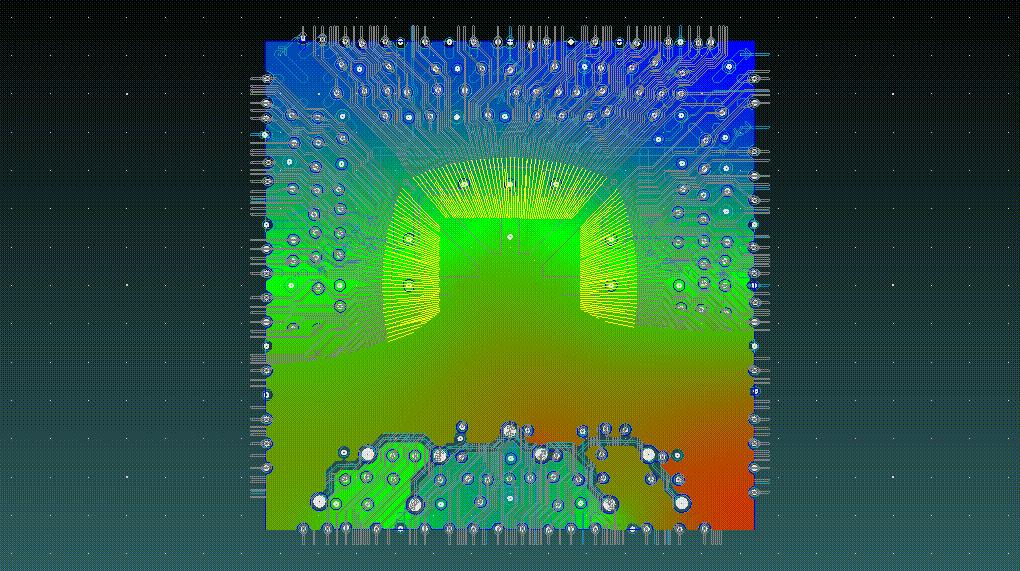


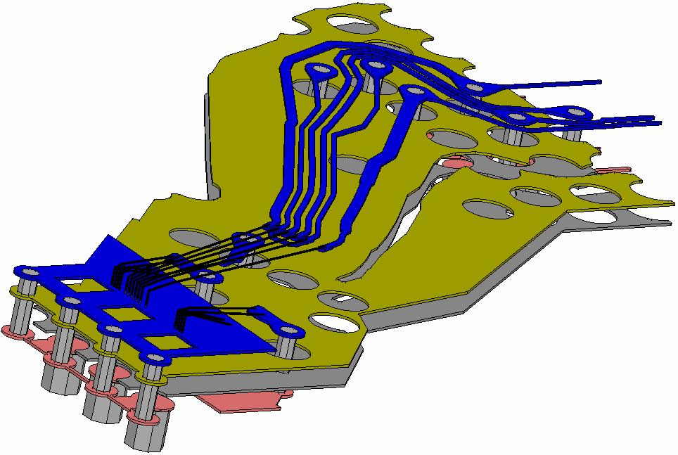


16 3D Parasitic Extraction 28 Ansoft, LLC All rights reserved. Ansoft, LLC Proprietary


17 Circuit & System Simulation SMA Connector S-Parameters logic_in PULLUP OUT logic_in pullup out Differential PRBS Microstrip Circuit Component Stripline Circuit Component enable PULLDOWN enable out_of _in pulldow n pullup POWER pu llup logic _in enable pulldow n GND out out_of _in BGA Package S-Parameters Dynamic Link to HFSS Via Model Dynamic Link to HFSS Stripline Transition Model lo gic_ in p ulldo w n OU T 28 Ansoft, LLC All rights reserved. Ansoft, LLC Proprietary


 Distribute")


18 Design Automation and Integration AnsoftLinks 3 rd part CAD interface PCB CAD : Cadence, Zuken, Mentor, Synopsys Fully setup, ready to solve HFSS and Q3D package models MCAD geometry: 3D CAD, IGES, STEP, Pro/E Optimetrics Automatic Optimization Parametric analysis Sensitivity Analysis Statistical Analysis DSO (Distributed Solve Option) Distribute solving of large parametric and sweep projects across network of computers Linear Speed Increase with number of computers Applicable to Q3D and HFSS Time (seconds) Distributed Solve One Computer 1x Speed-up 28 Ansoft, LLC All rights reserved. Ansoft, LLC Proprietary
 [mv] 61. 65. 6. 595. 59. 585")
![. 58. VCO tuning voltage (locking & settling transient). 5. 1. 15. 2. 25. 3. 35. 4. 45. 5. Time [ns] R1 V58 data_in V1=-.2 V2=.](/docs-images/84/91145572/images/19-2.jpg "2 TRF=1/data_rat/5 PW=4/data_rat/5 TONE= E2 GAIN=1 V34 E26 DC=.")


19 Name X Y m m1 Curve Info db(v(vco)-v(vcob)) Transient Virtual Measurement Environment Ansoft Corporation 615. XY Plot 7 Top_15cmTRL Curve Info Ansoft Corporation. XY Plot 8 Top_15cmTRL V(vco_tune) [mv] VCO tuning voltage (locking & settling transient) Time [ns] R1 V58 data_in V1=-.2 V2=.2 TRF=1/data_rat/5 PW=4/data_rat/5 TONE= E2 GAIN=1 V34 E26 DC=.782 GAIN=-1 V(vco_tune) Transient 5 R13 5 sig1_in sig2_in Input_ref db(v(vco)-v(vcob)) data datab Spectrum [GHz] sig1_out sig2_out Output_ref V27 DC= W65 agnd avdd avdd R16 v_irefp v_irefn 5 R19 Spectrum of VCO output (Clock output) 5 ch_out ch_outb in inb nbias vtune V4 DC=.6 agnd avdd out outb avdd V31 DC=1.2 eq_out eq_outb in inb agnd avdd CDR vcob vcob clk clkb out outb vco net164 vco_tune clk_o clk_ob cdr_data_o cdr_data_ob vco Eye & Jitter of VCO Output (=Clock Output) Channel Output CT Equalizer Output CDR Data Output 28 Ansoft, LLC All rights reserved. Ansoft, LLC Proprietary

 Channel to be Verified")

20 Signal Integrity / Power Integrity / EMI Full (PCIe, HDMI, etc.) Channel to be Verified 28 Ansoft, LLC All rights reserved. Ansoft, LLC Proprietary


21 Signal Integrity / Power Integrity / EMI Original Driver Filtered 1 Driver M Measurement Driver settings EMI is now sufficiently suppressed SIwave Pi Filter Added at IC output to Reduce Skew 28 Ansoft, LLC All rights reserved. Ansoft, LLC Proprietary
22 Ansoft High Frequency Solution HFSS EXTRACTION 3D Geometry Full-Wave EM analysis SYZ parameter extraction, propagation constant SYZ parameters, Port Zo, Fields Nexxim SIMULATION High capacity, high speed circuit simulation engine Transistor level Tx/Rx models included Native support for HSpice and Spectre Time and Frequency domain SPICE/ Measured Data import Designer Sensitivity Analysis Fully Integrated Single EM/Circuit Solution Design management tool DESIGN AUTOMATION AnsoftLinks 3 rd part CAD interface PCB CAD : Cadence, Zuken, Mentor, Synopsys MCAD geometry: 3D CAD, IGES, STEP, Pro/E Optimetrics Automatic Optimization Parametric analysis Statistical Analysis System Level Simulator Planar EM analysis Cascading models from different Ansoft tools DSO (Distributed Solve Option) Distribute solving of large parametric and sweep projects across network of computers Linear Speed Increase with number of computers Applicable to Q3D and HFSS 28 Ansoft, LLC All rights reserved. Ansoft, LLC Proprietary


23 High Performance High Frequency Applications Large Complex Solution Aircraft Model 28 Ansoft, LLC All rights reserved. Ansoft, LLC Proprietary


24 High Performance High Frequency Applications Antenna System Solution 28 Ansoft, LLC All rights reserved. Ansoft, LLC Proprietary


25 High Performance High Frequency Applications Bio-Medical Solution 28 Ansoft, LLC All rights reserved. Ansoft, LLC Proprietary


26 RF And Microwave 28 Ansoft, LLC All rights reserved. Ansoft, LLC Proprietary


27 High Performance High Frequency Applications EMI EMC Solution 28 Ansoft, LLC All rights reserved. Ansoft, LLC Proprietary
28 Conclusions IC Design & Verification Signal & Power Integrity RF & Microwave 1. Torque Output Electromechanical Systems ICA: LL:=922u LDUM:=1m 7.8 RA:=2.991 LA.I [A] LB.I [A] LC.I [A] PWM_T:=6 PWM_PER:=18 I_TARG:= m 3.m I_HYST:=.2 2.m 3.m 15 rpm + Q3 Q1 RA Ohm Q5 sourcea1 Magnet1 sourcea2 Magnet2 ω LL H sourceb1 sourceb2 4 V sourcec1 Q4 Q6 Q2 sourcec2 FEA THRES := PWM_T VAL[] := mod( INPUT[],INPUT[1] ) QS1 INPUT[1] := PWM_PER + Φ GAIN LA.I CONST -LC.I FEA Outputs 32.k 2.k -3.k Name FEA1.FEA_STEPS SIMPARAM1.RunTime [s] SIMPARAM1.TotalIterations SIMPARAM1.TotalSteps 2.m Value 26.41k 34.51k 6.k 3.m EQUBL 28 Ansoft, LLC All rights reserved. -9+PWM_PER CONST -12+PWM_PER CONST -15+PWM_PER EQUBL QS6 INPUT := -LB.I THRES1 := I_TARG - I_HYST EQUBL EQUBL Y := 1 VAL1 := 1 VAL2 := 8.5 Q1.CTRL Q2.CTRL + 6. Q3.CTRL Q4.CTRL + 3. Q5.CTRL Q6.CTRL 2.m -6+PWM_PER CONST QS5 LC.I 5. CONST EQUBL QS4 -LA.I THRES2 := I_TARG + I_HYST -3+PWM_PER QS3 LB.I FEA1.WIRELOSS FEA1.CORELOSS FEA1.IsourceA FEA1.VsourceA FEA1.EIsourceA FEA1.FLUXsourceA FEA1.IsourceB FEA1.VsourceB FEA1.EIsourceB FEA1.FLUXsourceB FEA1.IsourceC FEA1.VsourceC FEA1.EIsourceC FEA1.FLUXsourceC FEA1.PHI FEA1.OMEGA 8.5 ANGRAD 57.3 EQUBL QS2 3.m QS1.VAL QS2.VAL QS3.VAL QS4.VAL QS5.VAL QS6.VAL 5. 2.m m Ansoft, LLC Proprietary
ANSYS CPS SOLUTION FOR SIGNAL AND POWER INTEGRITY
 ANSYS CPS SOLUTION FOR SIGNAL AND POWER INTEGRITY Rémy FERNANDES Lead Application Engineer ANSYS 1 2018 ANSYS, Inc. February 2, 2018 ANSYS ANSYS - Engineering simulation software leader Our industry reach
EMI/EMC of Entire Automotive Vehicles and Critical PCB s. Makoto Suzuki Ansoft Corporation
 EMI/EMC of Entire Automotive Vehicles and Critical PCB s Makoto Suzuki Ansoft Corporation WT10_SI EMI/EMC of Entire Automotive Vehicles and Critical PCB s Akira Ohta, Toru Watanabe, Benson Wei Makoto Suzuki
Signal Integrity Modeling and Simulation for IC/Package Co-Design
 Signal Integrity Modeling and Simulation for IC/Package Co-Design Ching-Chao Huang Optimal Corp. October 24, 2004 Why IC and package co-design? The same IC in different packages may not work Package is
DesignCon Design of Gb/s Interconnect for High-bandwidth FPGAs. Sherri Azgomi, Altera Corporation
 DesignCon 2004 Design of 3.125 Gb/s Interconnect for High-bandwidth FPGAs Sherri Azgomi, Altera Corporation sazgomi@altera.com Lawrence Williams, Ph.D., Ansoft Corporation williams@ansoft.com CF-031505-1.0
Strategies for High Density and High Speed Packaging. Ride the Wave Workshop
 Strategies for High Density and High Speed Packaging Ride the Wave Workshop Topics! Trends in Packaging! Common Design Challenges! Design through Software! Supply Plane Analysis with SIwave! Non-ideal
Ansoft Designer with Nexxim. Statistical Eye Capabilities
 Ansoft Designer with Nexxim Statistical Eye Capabilities Problem Statement Load Generic 0.25um M odels Buffer PCIE Connector BYPASS Planar EM S S S TRL TRL TRL TRL TRL TRL Programmable W-Element SI Wave
How to anticipate Signal Integrity Issues: Improve my Channel Simulation by using Electromagnetic based model
 How to anticipate Signal Integrity Issues: Improve my Channel Simulation by using Electromagnetic based model HSD Strategic Intent Provide the industry s premier HSD EDA software. Integration of premier
Ansys Designer RF Training Lecture 3: Nexxim Circuit Analysis for RF
 Ansys Designer RF Solutions for RF/Microwave Component and System Design 7. 0 Release Ansys Designer RF Training Lecture 3: Nexxim Circuit Analysis for RF Designer Overview Ansoft Designer Advanced Design
Relationship Between Signal Integrity and EMC
 Relationship Between Signal Integrity and EMC Presented by Hasnain Syed Solectron USA, Inc. RTP, North Carolina Email: HasnainSyed@solectron.com 06/05/2007 Hasnain Syed 1 What is Signal Integrity (SI)?
EMI. Chris Herrick. Applications Engineer
 Fundamentals of EMI Chris Herrick Ansoft Applications Engineer Three Basic Elements of EMC Conduction Coupling process EMI source Emission Space & Field Conductive Capacitive Inductive Radiative Low, Middle
Using Sonnet EM Analysis with Cadence Virtuoso in RFIC Design. Sonnet Application Note: SAN-201B July 2011
 Using Sonnet EM Analysis with Cadence Virtuoso in RFIC Design Sonnet Application Note: SAN-201B July 2011 Description of Sonnet Suites Professional Sonnet Suites Professional is an industry leading full-wave
High-Performance Electronic Design: Predicting Electromagnetic Interference
 White Paper High-Performance Electronic Design: In designing electronics in today s highly competitive markets, meeting requirements for electromagnetic compatibility (EMC) presents a major risk factor,
ECEN 720 High-Speed Links: Circuits and Systems
 1 ECEN 720 High-Speed Links: Circuits and Systems Lab4 Receiver Circuits Objective To learn fundamentals of receiver circuits. Introduction Receivers are used to recover the data stream transmitted by
EMC cases study. Antonio Ciccomancini Scogna, CST of America CST COMPUTER SIMULATION TECHNOLOGY
 EMC cases study Antonio Ciccomancini Scogna, CST of America antonio.ciccomancini@cst.com Introduction Legal Compliance with EMC Standards without compliance products can not be released to the market Failure
ECEN 720 High-Speed Links Circuits and Systems
 1 ECEN 720 High-Speed Links Circuits and Systems Lab4 Receiver Circuits Objective To learn fundamentals of receiver circuits. Introduction Receivers are used to recover the data stream transmitted by transmitters.
Electromagnetic Simulation of Antennas Installed Inside Vehicles An Automotive EMC Approach Markus Kopp Product Manager, Electronics
 Electromagnetic Simulation of Antennas Installed Inside Vehicles An Automotive EMC Approach Markus Kopp Product Manager, Electronics 1 Automotive Antenna Systems and Automotive EMC Recent technology implementations
Electromagnetic Analysis and Verification of Probe Card Performance for First Pass System Success
 San Diego, CA Electromagnetic Analysis and Verification of Probe Card Performance for First Pass System Success Cristian Gozzi Application Engineer Manager Introduction Today in Multi Probe wafer level,
Evaluation of Package Properties for RF BJTs
 Application Note Evaluation of Package Properties for RF BJTs Overview EDA simulation software streamlines the development of digital and analog circuits from definition of concept and estimation of required
Lecture 5: Dynamic Link
 Lecture 5: Dynamic Link 2015.0 Release ANSYS HFSS for Antenna Design 1 2015 ANSYS, Inc. Antenna System Co-Simulation Transmit/Receive (T/R) Module Block Diagram Antenna Element Replicate Times Power
300 frequencies is calculated from electromagnetic analysis at only four frequencies. This entire analysis takes only four minutes.
 Electromagnetic Analysis Speeds RFID Design By Dr. James C. Rautio Sonnet Software, Inc. Liverpool, NY 13088 (315) 453-3096 info@sonnetusa.com http://www.sonnetusa.com Published in Microwaves & RF, February
RF MEMS Simulation High Isolation CPW Shunt Switches
 RF MEMS Simulation High Isolation CPW Shunt Switches Authored by: Desmond Tan James Chow Ansoft Corporation Ansoft 2003 / Global Seminars: Delivering Performance Presentation #4 What s MEMS Micro-Electro-Mechanical
Electrical Test Vehicle for High Density Fan-Out WLP for Mobile Application. Institute of Microelectronics 22 April 2014
 Electrical Test Vehicle for High Density Fan-Out WLP for Mobile Application Institute of Microelectronics 22 April 2014 Challenges for HD Fan-Out Electrical Design 15-20 mm 7 mm 6 mm SI/PI with multilayer
Constructing conducted emission models for integrated circuits
 Scholars' Mine Masters Theses Student Research & Creative Works Fall 2013 Constructing conducted emission models for integrated circuits Shuai Jin Follow this and additional works at: http://scholarsmine.mst.edu/masters_theses
Closing the loop part 1: Why use simulation tools for high speed signal channel design?
 Closing the loop part 1: Why use simulation tools for high speed signal channel design? Riccardo Giacometti Application Engineer Agilent EEsof EDA Page 1 High Speed Digital Design Flow Pre-Layout w/channel
Nonlinear Effects in Active Phased Array System Performance
 Nonlinear Effects in Active Phased Array System Performance Larry Williams, PhD Director of Product Management ANSYS Inc. 1 Advanced Simulation Simulate the Complete Product Real-life behavior in real-world
Reliable World Class Insights Your Silicon Valley Partner in Simulation ANSYS Sales, Consulting, Training & Support
 www.ozeninc.com info@ozeninc.com (408) 732 4665 1210 E Arques Ave St 207 Sunnyvale, CA 94085 Reliable World Class Insights Your Silicon Valley Partner in Simulation ANSYS Sales, Consulting, Training &
Trends in RF/Microwave & High Speed Digital and their effect on PCB Technology Requirements
 Trends in RF/Microwave & High Speed Digital and their effect on PCB Technology Requirements Jim Francey Technical Service Manager The need for speed is satisfied by the delivery of high-speed broadband
A Novel Embedded Common-mode Filter for above GHz differential signals based on Metamaterial concept. Tzong-Lin Wu
 c //3 A Novel Embedded Common-mode Filter for above GHz differential signals based on Metamaterial concept Tzong-Lin Wu Professor Graduate Institute of Communication Engineering, National Taiwan University,
DesignCon Full Chip Signal and Power Integrity with Silicon Substrate Effect. Norio Matsui Dileep Divekar Neven Orhanovic
 DesignCon 2004 Chip-Level Physical Design Full Chip Signal and Power Integrity with Silicon Substrate Effect Norio Matsui Dileep Divekar Neven Orhanovic Applied Simulation Technology, Inc. 408-436-9070
A Technical Discussion of TDR Techniques, S-parameters, RF Sockets, and Probing Techniques for High Speed Serial Data Designs
 A Technical Discussion of TDR Techniques, S-parameters, RF Sockets, and Probing Techniques for High Speed Serial Data Designs Presenter: Brian Shumaker DVT Solutions, LLC, 650-793-7083 b.shumaker@comcast.net
Taking the Mystery out of Signal Integrity
 Slide - 1 Jan 2002 Taking the Mystery out of Signal Integrity Dr. Eric Bogatin, CTO, GigaTest Labs Signal Integrity Engineering and Training 134 S. Wolfe Rd Sunnyvale, CA 94086 408-524-2700 www.gigatest.com
PCB Routing Guidelines for Signal Integrity and Power Integrity
 PCB Routing Guidelines for Signal Integrity and Power Integrity Presentation by Chris Heard Orange County chapter meeting November 18, 2015 1 Agenda Insertion Loss 101 PCB Design Guidelines For SI Simulation
CST s commercial Beam-Physics Codes Ulrich Becker CST (Computer Simulation Technique)
") CST s commercial Beam-Physics Codes Ulrich Becker CST (Computer Simulation Technique) 1 ICAP 2006 Chamonix-Mont Blanc Ulrich Becker www.cst.com Outline Overview CST STUDIO SUITE Accelerator related examples
CST s commercial Beam-Physics Codes Ulrich Becker CST (Computer Simulation Technique) 1 ICAP 2006 Chamonix-Mont Blanc Ulrich Becker www.cst.com Outline Overview CST STUDIO SUITE Accelerator related examples
Case Study Package Design & SI/PI analysis
 Caliber Interconnect Solutions Design for perfection Case Study Package Design & SI/PI analysis Caliber Interconnect Solutions (Pvt) Ltd No 6,1 st Street Gandhi Nagar, Kavundampalayam, Coimbatore-30. Tamil
TIE Plus. The step towards interconnect simulation technology
 Bitte decken Sie die schraffierte Fläche mit einem Bild ab. Please cover the shaded area with a picture. (24,4 x 11,0 cm) TIE Plus. The step towards interconnect simulation technology Catalin Negrea, Ph.
MMIC/RFIC Packaging Challenges Webcast (July 28, AM PST 12PM EST)
") MMIC/RFIC Packaging Challenges Webcast ( 9AM PST 12PM EST) Board Package Chip HEESOO LEE Agilent EEsof 3DEM Technical Lead 1 Agenda 1. MMIC/RFIC packaging challenges 2. Design techniques and solutions
MMIC/RFIC Packaging Challenges Webcast ( 9AM PST 12PM EST) Board Package Chip HEESOO LEE Agilent EEsof 3DEM Technical Lead 1 Agenda 1. MMIC/RFIC packaging challenges 2. Design techniques and solutions
Demystifying Vias in High-Speed PCB Design
 Demystifying Vias in High-Speed PCB Design Keysight HSD Seminar Mastering SI & PI Design db(s21) E H What is Via? Vertical Interconnect Access (VIA) An electrical connection between layers to pass a signal
MSPP Page 1. MSPP Competencies in SiP Integration for Wireless Applications
 MSPP Page 1 MSPP Competencies in SiP Integration for Wireless Applications MSPP Page 2 Outline Design, simulation and measurements tools MSPP competencies in electrical design and modeling Embedded passive
COMPACT DESIGN AND SIMULATION OF LOW PASS MICROWAVE FILTER ON MICROSTRIP TRANSMISSION LINE AT 2.4 GHz
 International Journal of Management, IT & Engineering Vol. 7 Issue 7, July 2017, ISSN: 2249-0558 Impact Factor: 7.119 Journal Homepage: Double-Blind Peer Reviewed Refereed Open Access International Journal
ABSTRACT. As data frequency increases beyond several Gbps range, low power chip to chip
 ABSTRACT SHAH, CHINTAN HEMENDRA. Inductively Coupled Interconnect for Chip to Chip Communication over Transmission Line. (Under the direction of Dr. Paul Franzon). As data frequency increases beyond several
Differential Signaling is the Opiate of the Masses
 Differential Signaling is the Opiate of the Masses Sam Connor Distinguished Lecturer for the IEEE EMC Society 2012-13 IBM Systems & Technology Group, Research Triangle Park, NC My Background BSEE, University
Ensuring Signal and Power Integrity for High-Speed Digital Systems
 Ensuring Signal and Power Integrity for High-Speed Digital Systems An EMC Perspective Christian Schuster Institut für Theoretische Elektrotechnik Technische Universität Hamburg-Harburg (TUHH) Invited Presentation
Highly Accurate and Robust Automotive Radar System Design. Markus Kopp Lead Application Specialist ANSYS Inc.
 Highly Accurate and Robust Automotive Radar System Design Markus Kopp Lead Application Specialist ANSYS Inc. Introduction This presentation is an overview of a proposed design methodology for automotive
DDR4 memory interface: Solving PCB design challenges
 DDR4 memory interface: Solving PCB design challenges Chang Fei Yee - July 23, 2014 Introduction DDR SDRAM technology has reached its 4th generation. The DDR4 SDRAM interface achieves a maximum data rate
EM Analysis of RFIC Inductors and Transformers. Dr.-Ing. Volker Mühlhaus Dr. Mühlhaus Consulting & Software GmbH, Witten
 EM Analysis of RFIC Inductors and Transformers Dr.-Ing. Volker Mühlhaus, Witten Do you love inductors? Image Kansas State University Inductors from the design kit tend to have the wrong value, optimized
Experience at INFN Padova on constrained PCB design Roberto Isocrate INFN-Padova
 Experience at INFN Padova on constrained PCB design Roberto Isocrate INFN-Padova Experience at INFN Padova on constrained design 1. Why do we need Signal Integrity (SI) analysis (and constrained design)?
Measuring Hot TDR and Eye Diagrams with an Vector Network Analyzer?
 Measuring Hot TDR and Eye Diagrams with an Vector Network Analyzer? Gustaaf Sutorius Application Engineer Agilent Technologies gustaaf_sutorius@agilent.com Page 1 #TDR fit in Typical Digital Development
Keysight Technologies Signal Integrity Tips and Techniques Using TDR, VNA and Modeling
 Keysight Technologies Signal Integrity Tips and Techniques Using, VNA and Modeling Article Reprint This article first appeared in the March 216 edition of Microwave Journal. Reprinted with kind permission
Touchstone v2.0 SI/PI S- Parameter Models for Simultaneous Switching Noise (SSN) Analysis of DDR4 Memory Interface Applications.
 Analysis of DDR4 Memory Interface Applications.") DesignCon 2014 Touchstone v2.0 SI/PI S- Parameter Models for Simultaneous Switching Noise (SSN) Analysis of DDR4 Memory Interface Applications. Romi Mayder, Xilinx, Inc. romi.mayder@xilinx.com Raymond
DesignCon 2014 Touchstone v2.0 SI/PI S- Parameter Models for Simultaneous Switching Noise (SSN) Analysis of DDR4 Memory Interface Applications. Romi Mayder, Xilinx, Inc. romi.mayder@xilinx.com Raymond
Optimization of Wafer Level Test Hardware using Signal Integrity Simulation
 June 7-10, 2009 San Diego, CA Optimization of Wafer Level Test Hardware using Signal Integrity Simulation Jason Mroczkowski Ryan Satrom Agenda Industry Drivers Wafer Scale Test Interface Simulation Simulation
Agilent EEsof EDA. Enabling First Pass Success. Chee Keong, Teo Business Development Manager EEsof South Asia. Agilent Restricted
 Agilent EEsof EDA Enabling First Pass Success Chee Keong, Teo Business Development Manager EEsof South Asia EEsof EDA is Strategic to Agilent Technologies As the world s premier measurement company, Agilent
Methods and Approaches for RF Circuit Simulation And Electromagnetic Modelling
 Methods and Approaches for RF Circuit Simulation And Electromagnetic Modelling T.A.M. Kevenaar 1, E.J.W. ter Maten 1, H.H.J. Janssen 1, S. Onneweer 2 1 Philips Research, Eindhoven, The Netherlands 2 Philips
L-BAND COPLANAR SLOT LOOP ANTENNA FOR INET APPLICATIONS
 L-BAND COPLANAR SLOT LOOP ANTENNA FOR INET APPLICATIONS Jeyasingh Nithianandam Electrical and Computer Engineering Department Morgan State University, 500 Perring Parkway, Baltimore, Maryland 5 ABSTRACT
Low Jitter, Low Emission Timing Solutions For High Speed Digital Systems. A Design Methodology
 Low Jitter, Low Emission Timing Solutions For High Speed Digital Systems A Design Methodology The Challenges of High Speed Digital Clock Design In high speed applications, the faster the signal moves through
SIGNAL INTEGRITY ANALYSIS AND MODELING
 1.00mm Pitch BGA Socket Adapter System SIGNAL INTEGRITY ANALYSIS AND MODELING Rev. 2 www.advanced.com Signal Integrity Data Reporting At Advanced Interconnections Corporation, our Signal Integrity reporting
APPH6040B / APPH20G-B Specification V2.0
 APPH6040B / APPH20G-B Specification V2.0 (July 2014, Serial XXX-XX33XXXXX-XXXX or higher) A fully integrated high-performance cross-correlation signal source analyzer for to 7 or 26 GHz 1 Introduction
Design and Matching of a 60-GHz Printed Antenna
 Application Example Design and Matching of a 60-GHz Printed Antenna Using NI AWR Software and AWR Connected for Optenni Figure 1: Patch antenna performance. Impedance matching of high-frequency components
Signal Technologies 1
 Signal Technologies 1 Gunning Transceiver Logic (GTL) - evolution Evolved from BTL, the backplane transceiver logic, which in turn evolved from ECL (emitter-coupled logic) Setup of an open collector bus
ON-CHIP TECHNOLOGY INDEPENDENT 3-D MOD- ELS FOR MILLIMETER-WAVE TRANSMISSION LINES WITH BEND AND GAP DISCONTINUITY
 Progress In Electromagnetics Research B, Vol. 22, 171 185, 2010 ON-CHIP TECHNOLOGY INDEPENDENT 3-D MOD- ELS FOR MILLIMETER-WAVE TRANSMISSION LINES WITH BEND AND GAP DISCONTINUITY G. A. Wang, W. Woods,
Si-Interposer Collaboration in IC/PKG/SI. Eric Chen
 Si-Interposer Collaboration in IC/PKG/SI Eric Chen 4/Jul/2014 Design Overview U-bump Logic IC Mem IC C4 bump Logic IC Silicon/Organic substrate Interposer Mem IC CAP Package substrate Solder Ball VRM BGA
Modeling Physical PCB Effects 5&
 Abstract Getting logical designs to meet specifications is the first step in creating a manufacturable design. Getting the physical design to work is the next step. The physical effects of PCB materials,
To learn statistical bit-error-rate (BER) simulation, BER link noise budgeting and using ADS to model high speed I/O link circuits
 simulation, BER link noise budgeting and using ADS to model high speed I/O link circuits") 1 ECEN 720 High-Speed Links: Circuits and Systems Lab6 Link Modeling with ADS Objective To learn statistical bit-error-rate (BER) simulation, BER link noise budgeting and using ADS to model high speed
1 ECEN 720 High-Speed Links: Circuits and Systems Lab6 Link Modeling with ADS Objective To learn statistical bit-error-rate (BER) simulation, BER link noise budgeting and using ADS to model high speed
High Speed Clock Distribution Design Techniques for CDC 509/516/2509/2510/2516
 High Speed Clock Distribution Design Techniques for CDC 509/516/2509/2510/2516 APPLICATION REPORT: SLMA003A Boyd Barrie Bus Solutions Mixed Signals DSP Solutions September 1998 IMPORTANT NOTICE Texas Instruments
v14.0 LF Electromagnetics Update
 v14.0 LF Electromagnetics Update and HF Introduction o Mark Christini ANSYS, Inc 1 ANSYS, Inc. September 12, 2 ANSYS Workbench R14 Highlights Simplorer Co simulation with RBD Push Back excitations for
Case Study: Spice Macromodeling for PCI Express using IBIS 4.2
 INVENTIVE Case Study: Spice Macromodeling for PCI Express using IBIS 4.2 Lance Wang Email: lwang@cadence.com IBIS Asian Summit Oct. 27 th, 2006, Shanghai, China Outline PCI Express Serial Link Macromodeling
To learn S-parameters, eye diagram, ISI, modulation techniques and their simulations in MATLAB and Cadence.
 1 ECEN 720 High-Speed Links: Circuits and Systems Lab2- Channel Models Objective To learn S-parameters, eye diagram, ISI, modulation techniques and their simulations in MATLAB and Cadence. Introduction
Time Domain EM Modelling. W. Simon, , serv0
 Time Domain EM Modelling Introduction 3D full wave electromagnetic field solver (FDTD) Accurate: Validated with theory & measurements Versatile: Covering all passive RF-structures Efficient: Low memory
IBIS Data for CML,PECL and LVDS Interface Circuits
 Application Note: HFAN-06.2 Rev.1; 04/08 IBIS Data for CML,PECL and LVDS Interface Circuits AVAILABLE IBIS Data for CML,PECL and LVDS Interface Circuits 1 Introduction The integrated circuits found in
The Challenges of Differential Bus Design
 The Challenges of Differential Bus Design February 20, 2002 presented by: Arthur Fraser TechKnowledge Page 1 Introduction Background Historically, differential interconnects were often twisted wire pairs
Signal Integrity Tips and Techniques Using TDR, VNA and Modeling. Russ Kramer O.J. Danzy
 Signal Integrity Tips and Techniques Using TDR, VNA and Modeling Russ Kramer O.J. Danzy Simulation What is the Signal Integrity Challenge? Tx Rx Channel Asfiakhan Dreamstime.com - 3d People Communication
Electronic Circuit Simulation Tools Using Pspice On Ac Analysis
 Electronic Circuit Simulation Tools Using Pspice On Ac Analysis This Design Idea shows it can handle digital filter simulation too. PSpice has become an industry standard tool for analog circuit simulations.
PDS Impact for DDR Low Cost Design
 PDS Impact for DDR3-1600 Low Cost Design Jack W.C. Lin Sr. AE Manager jackl@cadence.com Aug. g 13 2013 Cadence, OrCAD, Allegro, Sigrity and the Cadence logo are trademarks of Cadence Design Systems, Inc.
Signal Integrity Design of TSV-Based 3D IC
 Signal Integrity Design of TSV-Based 3D IC October 24, 21 Joungho Kim at KAIST joungho@ee.kaist.ac.kr http://tera.kaist.ac.kr 1 Contents 1) Driving Forces of TSV based 3D IC 2) Signal Integrity Issues
Characterization Methodology for High Density Microwave Fixtures. Dr. Brock J. LaMeres, Montana State University
 DesignCon 2008 Characterization Methodology for High Density Microwave Fixtures Dr. Brock J. LaMeres, Montana State University lameres@ece.montana.edu Brent Holcombe, Probing Technology, Inc brent.holcombe@probingtechnology.com
Preliminary Product Overview
 Preliminary Product Overview Features DC to > 3 GHz Frequency Range 25 Watt (CW), 200W (Pulsed) Max Power Handling Low On-State Insertion Loss, typical 0.3 db @ 3 GHz Low On-State Resistance < 0.75 Ω 25dB
ON THE STUDY OF LEFT-HANDED COPLANAR WAVEGUIDE COUPLER ON FERRITE SUBSTRATE
 Progress In Electromagnetics Research Letters, Vol. 1, 69 75, 2008 ON THE STUDY OF LEFT-HANDED COPLANAR WAVEGUIDE COUPLER ON FERRITE SUBSTRATE M. A. Abdalla and Z. Hu MACS Group, School of EEE University
Optimizing Design of a Probe Card using a Field Solver
 Optimizing Design of a Probe Card using a Field Solver Rey Rincon, r-rincon@ti.com Texas Instruments 13020 Floyd Rd MS 3616 Dallas, TX. 75243 972-917-4303 Eric Bogatin, bogatin@ansoft.com Bill Beale, beale@ansoft.com
Operating Instructions
 6 18 GHz Frequency Synthesizer PFS-618-CD-1 Operating Instructions 1) Frequency Control The Frequency Control Code is constructed of 17 bits (A0 - A16). The following equation and table describe the frequency
Realize Your Product Promise. Maxwell
 Realize Your Product Promise Maxwell DC permanent magnet motor solved by Maxwell with ANSYS RMxprt Build reliability and efficiency into your electromagnetic and electromechanical designs with ANSYS Maxwell.
Innovations in EDA Webcast Series
 Welcome Innovations in EDA Webcast Series August 2, 2012 Jack Sifri MMIC Design Flow Specialist IC, Laminate, Package Multi-Technology PA Module Design Methodology Realizing the Multi-Technology Vision
IBIS in the Frequency Domain. Michael Mirmak Intel Corporation DAC IBIS Summit 2006 July 25, 2006
 IBIS in the Frequency Domain Michael Mirmak Intel Corporation DAC IBIS Summit 2006 July 25, 2006 Agenda Frequency Domain and Related Aspects Area 1: Maximum Switching Frequency Area 2: C_comp Stability
High Speed Design Issues and Jitter Estimation Techniques. Jai Narayan Tripathi
 High Speed Design Issues and Jitter Estimation Techniques Jai Narayan Tripathi (jainarayan.tripathi@st.com) Outline Part 1 High-speed Design Issues Signal Integrity Power Integrity Jitter Power Delivery
PI6C557-03AQ. PCIe 2.0 Clock Generator with 2 HCSL Outputs for Automotive Applications. Description. Features. Pin Configuration (16-Pin TSSOP)
") PCIe.0 Clock Generator with HCSL Outputs for Automotive Applications Features ÎÎPCIe.0 compliant à à Phase jitter -.1ps RMS (typ) ÎÎLVDS compatible outputs ÎÎSupply voltage of 3.3V ±10% ÎÎ5MHz crystal
PCIe.0 Clock Generator with HCSL Outputs for Automotive Applications Features ÎÎPCIe.0 compliant à à Phase jitter -.1ps RMS (typ) ÎÎLVDS compatible outputs ÎÎSupply voltage of 3.3V ±10% ÎÎ5MHz crystal
EMC analysis workflow
 EMC analysis workflow Antonio Ciccomancini Scogna, CST of America antonio.ciccomancini@cst.com EMC/EMI Applications Emissions Susceptibility E3 Typical Emissions Issues 1 2 Image courtesy of Johnson Controls
10 COVER FEATURE CAD/EDA FOCUS
 10 COVER FEATURE CAD/EDA FOCUS Effective full 3D EMI analysis of complex PCBs by utilizing the latest advances in numerical methods combined with novel time-domain measurement technologies. By Chung-Huan
SIwave DC Inductance Solver Computing Low Frequency Inductance from Current Density
 Application Brief SIwave DC Inductance Solver Computing Low Frequency Inductance from Current Density ANSYS SIwave introduces a feature in the DC solver that computes the low frequency inductance from
Power Plane and Decoupling Optimization. Isaac Waldron
 Power Plane and Decoupling Optimization p Isaac Waldron Overview Frequency- and time-domain power distribution system specifications Decoupling design example Bare board Added d capacitors Buried Capacitance
Design, Optimization, Fabrication, and Measurement of an Edge Coupled Filter
 SYRACUSE UNIVERSITY Design, Optimization, Fabrication, and Measurement of an Edge Coupled Filter Project 2 Colin Robinson Thomas Piwtorak Bashir Souid 12/08/2011 Abstract The design, optimization, fabrication,
The Ground Myth IEEE. Bruce Archambeault, Ph.D. IBM Distinguished Engineer, IEEE Fellow 18 November 2008
 The Ground Myth Bruce Archambeault, Ph.D. IBM Distinguished Engineer, IEEE Fellow barch@us.ibm.com 18 November 2008 IEEE Introduction Electromagnetics can be scary Universities LOVE messy math EM is not
Comparative Analysis of Intel Pentium 4 and IEEE/EMC TC-9/ACEM CPU Heat Sinks
 Comparative Analysis of Intel Pentium 4 and IEEE/EMC TC-9/ACEM CPU Heat Sinks Author Lu, Junwei, Duan, Xiao Published 2007 Conference Title 2007 IEEE International Symposium on Electromagnetic Compatibility
EMI Modeling of a 32-bit Microcontroller in Wait Mode
 EMI Modeling of a 32-bit Microcontroller in Wait Mode Jean-Pierre Leca 1,2, Nicolas Froidevaux 1, Henri Braquet 2, Gilles Jacquemod 2 1 STMicroelectronics, 2 LEAT, UMR CNRS-UNS 6071 BMAS 2010 San Jose,
Complete RF And Microwave Design Flow with AWR Design Environment. Tabish Khan, AWR Corporation
 Complete RF And Microwave Design Flow with AWR Design Environment Tabish Khan, AWR Corporation Traditional Serial Design Flow Separate tools, user interfaces, netlists and databases System Design Design
Design and Optimization of a Novel 2.4 mm Coaxial Field Replaceable Connector Suitable for 25 Gbps System and Material Characterization up to 50 GHz
 Design and Optimization of a Novel 2.4 mm Coaxial Field Replaceable Connector Suitable for 25 Gbps System and Material Characterization up to 50 GHz Course Number: 13-WA4 David Dunham, Molex Inc. David.Dunham@molex.com
High Speed Digital Design & Verification Seminar. Measurement fundamentals
 High Speed Digital Design & Verification Seminar Measurement fundamentals Agenda Sources of Jitter, how to measure and why Importance of Noise Select the right probes! Capture the eye diagram Why measure
Narrowband Combline Filter Design with ANSYS HFSS
 Narrowband Combline Filter Design with ANSYS HFSS Daniel G. Swanson, Jr. DGS Associates, LLC Boulder, CO dan@dgsboulder.com www.dgsboulder.com Introduction N = 6 Inline, Cover Loaded, Combline Filter Single
Validation Report Comparison of Eye Patterns Generated By Synopsys HSPICE and the Agilent PLTS
 Comparison of Eye Patterns Generated By Synopsys HSPICE and the Agilent PLTS Using: Final Inch Test/Eval Kit, Differential Pair - No Grounds Configuration, QTE-DP/QSE-DP, 5mm Stack Height (P/N FIK-QxE-04-01)
Thank you for downloading one of our ANSYS whitepapers we hope you enjoy it.
 Thank you! Thank you for downloading one of our ANSYS whitepapers we hope you enjoy it. Have questions? Need more information? Please don t hesitate to contact us! We have plenty more where this came from.
Nonlinear Full Wave Time Domain Solutions using FDTD_SPICE for High Speed Digital and RF
 Nonlinear Full Wave Time Domain Solutions using FDTD_SPICE for High Speed Digital and RF Neven Orhanovic Raj Raghuram Norio Matsui 1641 North First Street, Ste 170 San Jose, CA-95112 PH: 408-436-9070 FAX:
Frequency Multiplier Development at e2v Technologies
 Frequency Multiplier Development at e2v Technologies Novak Farrington UK Millimetre-Wave User Group Meeting National Physical Laboratory 05-10-09 Outline Sources available Brief overview of doubler operation
Schematic-Level Transmission Line Models for the Pyramid Probe
 Schematic-Level Transmission Line Models for the Pyramid Probe Abstract Cascade Microtech s Pyramid Probe enables customers to perform production-grade, on-die, full-speed test of RF circuits for Known-Good