Highly Accurate and Robust Automotive Radar System Design. Markus Kopp Lead Application Specialist ANSYS Inc.
|
|
|
- Andrew Malone
- 6 years ago
- Views:
Transcription


1 Highly Accurate and Robust Automotive Radar System Design Markus Kopp Lead Application Specialist ANSYS Inc.
2 Introduction This presentation is an overview of a proposed design methodology for automotive radar systems. This presentation is meant to illustrate the advantages of simulation, as well as what can be reasonably simulated using state of the art electromagnetic field solvers. This presentation will concentrate on how to address some of the challenges faced when designing radar systems at, the very high, 77 GHz frequency. All results shown in this presentation were created using ANSYS HFSS RF.


3 HFSS RF Mechanical CAD (MCAD) Both interfaces Electrical are included Layout (ECAD) within the new unified desktop environment

4 HFSS RF HFSS RF using the new unified design environment also allows RF and μwave frequency domain circuit design Analysis types Linear Harmonic Balance Transient Loadpull Envelope PXF Analyses Oscillator TV Noise Phase Noise PlanarEM Simulations

5 Creating an Antenna Array Single Antenna Element Design


6 Initial Design Initial Design is implemented in HFSS for Layout interface Initial Designs are synthesized using built in calculators Transmission Line (TRL) Tool Antenna Estimator Tool Both tools use stackup definition provided by engineer


7 Initial Antenna Design Initial Design is created in layout Then solved using a planar MoM solver For simple structures MoM solver is extremely fast


8 Initial Planar EM Results (MoM) After some tweaking excellent S11 results are obtained However, Mom solver prefer 2D infinitely thin conductors At 77 GHz the finite thickness of the metal may change performance
 thick metal produces different S11 results HFSS 3D clearly shows that more tweaking is needed")
9 3D thick Metal Results Re-simulating same antenna with mm (half ounce) thick metal produces different S11 results HFSS 3D clearly shows that more tweaking is needed Fine tuning will be done in HFSS-3D using adjoint derivatives


10 Rapid Antenna Tuning using Adjoint Derivatives Functionality (only available in HFSS 3D) Extremely efficient method used for tuning, sensitivity studies, and optimization Computes the derivatives of SYZ parameters with respect to project and design variables Eliminates need to solve multiple variations with small differences and numerical noise Allows real-time tuning of reports to explore effects of small design changes


11 Final Antenna Element Performance


12 Creating an Antenna Array Antenna Array Design
13 Creating an Antenna Array Creating an array once the unit antenna has been design is a straight forward process Antenna elements are arranged in a specific pattern, and then a net resultant antenna performance can be calculated This final antenna performance metric can be obtained using an antenna factor calculation or using an infinite array approximation or a finite sized antenna array can be simulated. Both the Antenna Factor calculation or the infinite array calculation are likely to produce erroneous results with regard to side lobes and back lobes A finite array calculation will provide the best results Simulating a finite array can be time consuming especially when the exact array spacing is still being determined


14 Finite Array Domain Decomposition (FA-DDM) Utilizes Replicated DDM Unit Cell to Address Array Concerns Geometry and Mesh copied directly from Unit Cell Model Unit Cell geometry expanded to finite array through a simple GUI Adaptive Meshing Process imported from Unit Cell Simulation Dramatically reduces the meshing time associated with finite array analyses. Mesh periodicity reinforces array s periodicity.
 with domain decomposition")

15 Finite Array Calculation using FA-DDM Efficient solution for repeating geometries (array) with domain decomposition technique (DDM) Direct solver with 12 cores 5:05: GB RAM Patterns from 8X8 Array Finite Array DDM with 12 cores 00:44: GB
 can be determined efficiently and quickly Slave Master")
16 Unit Cell Model for FA-DDM Unit cell model uses the HFSS Linked Boundaries Master and slaves boundaries are applied on opposite faces With and depth of unit cell determines antenna array element spacing Optimal array spacing (it s not lambda) can be determined efficiently and quickly Slave Master

17 Finite Array Capability Initial Array was modeled using FA-DDM Array spacing was optimized using FA-DDM Final 1 x 10 Array shows good performance


18 Explicit 1 X 10 Array Solution Final 1 X 10 Array was also explicitly simulated in HFSS 3D

19 Comparison of Explicit and FA-DDM Results Results between explicit HFSS 3D simulation and FA-DDM show excellent agreement FA-DDM has clear time advantage however and lends itself to rapid tuning of element spacing
20 Creating an Antenna Array Power Divider Design


21 Initial Divider Design Initial Design was again created in HSS Layout and analyzed using MoM solver for efficiency reasons However, similarly to antenna, finite thickness of metal makes a difference so Power divider was tuned in similar manner

22 Final 10 way Power Divider Design Final 10 way Power divider was designed To have the following power distribution , 0.125, 0.25,0.5, 1,1,0.5, 0.25,0.125,
23 Final 10 way Power Divider Design
24 Creating a Transmit/Receive Module Designing a 77 GHz Automotive Radar Module


25 Effect of Feed Network on Antenna Pattern The feed network will effect the antenna array performance. Simulating our array with attached feed network can show how detrimental the feed network is to our overall array performance No Feed With Feed


26 Radar Tx/RX Module Final Module consisted of 1X 10 Transmit Array 1 X 10 Receive Array Matching feed networks for TX and RX sides Radome of 1mm thickness Duroid er=9.8, 5 mil thick substrate


27 Antenna Pattern for full TX/RX Module


28 Effect of Radome on Array Performance Radome housing reduces back lobes but also flattens and widens main lobe Radome and antenna spacings can be optimized to reduce this effect


29 Final Module Design These optimized results are inclusive of plastic Radome, finite ground planes, feed network and TX/RX antenna structures


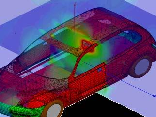
30 Full System Simulation Placing an Antenna Module inside a Car
31 Modeling an Antenna Array in its Deployment Environment Placing an Antenna Module in its deployment environment can be a very large and time consuming simulation. Using advanced modeling techniques and hybrid solvers can make these very large and time consuming simulations be manageable and efficient. Creating a hybrid FEM-MoM approach to solving very large simulations can be highly efficient and yield highly accurate results.

 Using a Hybrid Finite Element Method of")
32 TX/RX Module in Deployment Environment Car Hood (Perfect Electric Conductor) At 77 GHz this simulation is extremely large! Conventional simulation methods are not efficient. TXRX Module TXRX Module Car Bumper (Plastic) Using a Hybrid Finite Element Method of Moments Approach can be used to solve this model in an efficient and accurate manner


33 Hybrid Finite Element-Integral Equation Method Finite Element Based Method HFSS Efficient handle complex material and geometries Volume based mesh and field solutions Airbox required to model free space radiation Conformal radiation volume with Integral Equations Integral Equation Based Method HFSS-IE Efficient solution technique for open radiation and scattering Surface only mesh and current solution Airbox not needed to model free space radiation This Finite Element-Boundary Integral hybrid method leverages the advantages of both methods to Finite achieve Elements the most vs. accurate Integral and Equations robust solution for radiating and scattering problems


34 Finite Element-Boundary Integral = FEBI True solution to the open boundary condition Surface currents directly computed by IE solver Very accurate far fields No minimum distance from radiator Advantage over ABC Reflection-free boundary condition Ability to absorb incident fields is not dependent on the incident angle Arbitrary shaped boundary Outward facing normal's can intersect Can contain separated volumes FE-BI does come with a computational cost Ability to create air box with smaller volume than ABC or PML can significantly offset this cost Air volumes that much smaller than ABC/PML boundaries will be solvable in less RAM with FEBI

 2 G 2 ]/[16(πd/λ) 2 ] S11, ~0.3 and G ~4.")
35 FEBI Compare with Friis Transmission Two rectangular waveguide radiators contained in two separately spaced finite element and IE boundary domains Parametrically sweep separation and compare to theoretical Friis formula for free space transmission P r /P I = [(1- S 11 2 ) 2 G 2 ]/[16(πd/λ) 2 ] S11, ~0.3 and G ~4.5 computed from single radiator analysis
36 Transmit Antenna Location Investigation Proposed TX Antenna Location (Entire module not shown for clarity) High Location Low Location Using The FEBI method it is possible to investigate placement of Module within a deployment platform (Car, Truck, etc.) Effect of various plastic and metal obstructions can be evaluated Optimal Transmit antenna location can be determined


37 Transmit Antenna Location Investigation Low Antenna Pattern High Antenna Pattern


38 Transmit Antenna Location Investigation Low Antenna Pattern High Antenna Pattern
39 Obstructions at a Distance TX Array Large or infinite Metal Obstruction FEBI also allows engineers to place large or infinitely large obstructions at considerable distance from Antenna array. This can then be used to determine antenna performance in presence of obstruction or in a full system simulation where EM field solvers are combined with driving circuitry. This combined EM/circuit simulation is possible in HFSS RF but beyond the scope of todays presentation.


40 Obstructions at a Distance No Obstruction Large Obstruction at 5 m Distance


41 Obstructions at a Distance No Obstruction Large Obstruction at 5 m Distance
42 Final Thoughts Electromagnetic simulation can aid in the design of advanced radar modules helping to reduce time to market, design variability and manufacturing issues Advanced methods such as FEBI can be used to integrate Radar Modules into their deployment environment aiding design teams to ensure that Radar modules perform according to specifications Any questions?
Lecture 8: Introduction to Hybrid FEM IE
 Lecture 8: Introduction to Hybrid FEM IE 2015.0 Release ANSYS HFSS for Antenna Design 1 2015 ANSYS, Inc. Hybrid FEM-IE Solution Using HFSS and HFSS-IE Advantages of Hybrid Solution Leverage the strength
HFSS 13: Hybrid FE-BI for Efficient Simulation of Radiation and Scattering David Edgar Senior Application Engineer ANSYS Inc.
 HFSS 13: Hybrid FE-BI for Efficient Simulation of Radiation and Scattering David Edgar Senior Application Engineer ANSYS Inc. 2011 ANSYS, Inc. All rights reserved. 1 ANSYS, Inc. Proprietary Agenda FEM
Nonlinear Effects in Active Phased Array System Performance
 Nonlinear Effects in Active Phased Array System Performance Larry Williams, PhD Director of Product Management ANSYS Inc. 1 Advanced Simulation Simulate the Complete Product Real-life behavior in real-world
Electromagnetic Simulation of Antennas Installed Inside Vehicles An Automotive EMC Approach Markus Kopp Product Manager, Electronics
 Electromagnetic Simulation of Antennas Installed Inside Vehicles An Automotive EMC Approach Markus Kopp Product Manager, Electronics 1 Automotive Antenna Systems and Automotive EMC Recent technology implementations
Design and Matching of a 60-GHz Printed Antenna
 Application Example Design and Matching of a 60-GHz Printed Antenna Using NI AWR Software and AWR Connected for Optenni Figure 1: Patch antenna performance. Impedance matching of high-frequency components
EM Simulation of Automotive Radar Mounted in Vehicle Bumper
 EM Simulation of Automotive Radar Mounted in Vehicle Bumper Abstract Trends in automotive safety are pushing radar systems to higher levels of accuracy and reliable target identification for blind spot
EMDS for ADS Momentum
 EMDS for ADS Momentum ADS User Group Meeting 2009, Böblingen, Germany Prof. Dr.-Ing. Frank Gustrau Gustrau, Dortmund User Group Meeting 2009-1 Univ. of Applied Sciences and Arts (FH Dortmund) Presentation
Modeling Antennas with CREATE-RF's SENTRi Application
 Modeling Antennas with CREATE-RF's SENTRi Application Dr. Ryan Chilton, Dr. Jorge Villa-Giron, Dr. John D Angelo 1 CREATE-RF Requirement Summary Antennas on Air, Sea, Ground, and Space Platforms Communication,
When Should You Apply 3D Planar EM Simulation?
 When Should You Apply 3D Planar EM Simulation? Agilent EEsof EDA IMS 2010 MicroApps Andy Howard Agilent Technologies 1 3D planar EM is now much more of a design tool Solves bigger problems and runs faster
Lecture 5: Dynamic Link
 Lecture 5: Dynamic Link 2015.0 Release ANSYS HFSS for Antenna Design 1 2015 ANSYS, Inc. Antenna System Co-Simulation Transmit/Receive (T/R) Module Block Diagram Antenna Element Replicate Times Power
Using Sonnet EM Analysis with Cadence Virtuoso in RFIC Design. Sonnet Application Note: SAN-201B July 2011
 Using Sonnet EM Analysis with Cadence Virtuoso in RFIC Design Sonnet Application Note: SAN-201B July 2011 Description of Sonnet Suites Professional Sonnet Suites Professional is an industry leading full-wave
Design and Simulation of an ISM Band Antenna on PCB Technology
 Design and Simulation of an ISM Band Antenna on PCB Technology ISM radio bands have traditionally been reserved internationally for the use of radio frequencies (RF) for industrial, scientific, and medical
RF Board Design for Next Generation Wireless Systems
 RF Board Design for Next Generation Wireless Systems Page 1 Introduction Purpose: Provide basic background on emerging WiMax standard Introduce a new tool for Genesys that will aide in the design and verification
L-BAND COPLANAR SLOT LOOP ANTENNA FOR INET APPLICATIONS
 L-BAND COPLANAR SLOT LOOP ANTENNA FOR INET APPLICATIONS Jeyasingh Nithianandam Electrical and Computer Engineering Department Morgan State University, 500 Perring Parkway, Baltimore, Maryland 5 ABSTRACT
CFDTD Solution For Large Waveguide Slot Arrays
 I. Introduction CFDTD Solution For Large Waveguide Slot Arrays T. Q. Ho*, C. A. Hewett, L. N. Hunt SSCSD 2825, San Diego, CA 92152 T. G. Ready NAVSEA PMS5, Washington, DC 2376 M. C. Baugher, K. E. Mikoleit
Antenna Simulation Overview
 Antenna Simulation Overview Marc Rütschlin, Senior Application Engineer 2011 CST European UGM 18-19 May 2011 1 Antenna Choice Analysis Optimisation Environment Antenna Design Flow 2011 CST European UGM
The analysis of microstrip antennas using the FDTD method
 Computational Methods and Experimental Measurements XII 611 The analysis of microstrip antennas using the FDTD method M. Wnuk, G. Różański & M. Bugaj Faculty of Electronics, Military University of Technology,
High-Performance Electronic Design: Predicting Electromagnetic Interference
 White Paper High-Performance Electronic Design: In designing electronics in today s highly competitive markets, meeting requirements for electromagnetic compatibility (EMC) presents a major risk factor,
Multiscale Simulation for Automotive Radar
 Multiscale Simulation for Automotive Radar Marc Rütschlin Acknowledgments: Franz Hirtenfelder, Hassan Chreim Automotive Radar Architecture Our Topic Radar Architecture: Emitters and receivers (antennas)
FEKO-Based Method for Electromagnetic Simulation of Carcass Wires Embedded in Vehicle Tires
 ACES JOURNAL, VOL. 26, NO. 3, MARCH 2011 217 FEKO-Based Method for Electromagnetic Simulation of Carcass Wires Embedded in Vehicle Tires Nguyen Quoc Dinh 1, Takashi Teranishi 1, Naobumi Michishita 1, Yoshihide
Ansys Designer RF Training Lecture 3: Nexxim Circuit Analysis for RF
 Ansys Designer RF Solutions for RF/Microwave Component and System Design 7. 0 Release Ansys Designer RF Training Lecture 3: Nexxim Circuit Analysis for RF Designer Overview Ansoft Designer Advanced Design
Analysis of a Co-axial Fed Printed Antenna for WLAN Applications
 Analysis of a Co-axial Fed Printed Antenna for WLAN Applications G.Aneela 1, K.Sairam Reddy 2 1,2 Dept. of Electronics & Communication Engineering ACE Engineering College, Ghatkesar, Hyderabad, India.
Aut omot i ve EMI / EMC Si mul at i ons Usi ng ANSYS Hi gh Fr equency Tool s. Markus Kopp Product Manager, Electronics ANSYS, Inc.
 Aut omot i ve EMI / EMC Si mul at i ons Usi ng ANSYS Hi gh Fr equency Tool s 1 ANSYS, Inc. September 21, Markus Kopp Product Manager, Electronics ANSYS, Inc. System Engineering ISO/IEC15288:2008: "A combination
Chapter 1 - Antennas
 EE 483/583/L Antennas for Wireless Communications 1 / 8 1.1 Introduction Chapter 1 - Antennas Definition - That part of a transmitting or receiving system that is designed to radiate or to receive electromagnetic
Antenna Design: Simulation and Methods
 Antenna Design: Simulation and Methods Radiation Group Signals, Systems and Radiocommunications Department Universidad Politécnica de Madrid Álvaro Noval Sánchez de Toca e-mail: anoval@gr.ssr.upm.es Javier
Electromagnetic Band Gap Structures in Antenna Engineering
 Electromagnetic Band Gap Structures in Antenna Engineering FAN YANG University of Mississippi YAHYA RAHMAT-SAMII University of California at Los Angeles Hfl CAMBRIDGE Щ0 UNIVERSITY PRESS Contents Preface
Impact of the Coordinate System s Orientation
 April 25th 2016 Impact of the Coordinate System s Orientation Susanne Kürschner, KATHREIN-Werke KG Rosenheim Impact of the Coordinate System s Orientation 1. 2. 3. 4. Overview Simulation Settings Results
Modeling and Simulating Large Phased Array Systems
 Modeling and Simulating Large Phased Array Systems Tabrez Khan Senior Application Engineer Application Engineering Group 2015 The MathWorks, Inc. 1 Challenges with Large Array Systems Design & simulation
Determination of Transmission and Reflection Parameters by Analysis of Square Loop Metasurface
 Determination of Transmission and Reflection Parameters by Analysis of Square Loop Metasurface Anamika Sethi #1, Rajni *2 #Research Scholar, ECE Department, MRSPTU, INDIA *Associate Professor, ECE Department,
Modeling Techniques for Rapid Antenna Evaluation and the Power of Field Visualization
 Modeling Techniques for Rapid Antenna Evaluation and the Power of Field Visualization John Locke Technical Specialist, RF and Antenna Subsystems Ford Motor Company Introduction You are an Engineer Engineer
Effect of Slot Rotation on Rectangular Slot based Microstrip Patch Antenna
 International Journal of Current Engineering and Technology E-ISSN 2277 4106, P-ISSN 2347 5161 2015INPRESSCO, All Rights Reserved Available at http://inpressco.com/category/ijcet Research Article Effect
An Efficient Hybrid Method for Calculating the EMC Coupling to a. Device on a Printed Circuit Board inside a Cavity. by a Wire Penetrating an Aperture
 An Efficient Hybrid Method for Calculating the EMC Coupling to a Device on a Printed Circuit Board inside a Cavity by a Wire Penetrating an Aperture Chatrpol Lertsirimit David R. Jackson Donald R. Wilton
FDTD CHARACTERIZATION OF MEANDER LINE ANTENNAS FOR RF AND WIRELESS COMMUNICATIONS
 Progress In Electromagnetics Research, PIER 4, 85 99, 999 FDTD CHARACTERIZATION OF MEANDER LINE ANTENNAS FOR RF AND WIRELESS COMMUNICATIONS C.-W. P. Huang, A. Z. Elsherbeni, J. J. Chen, and C. E. Smith
Multilayer VIA simulations using ADS Anurag Bhargava, Application Consultant, Agilent EEsof EDA, Agilent Technologies
 Multilayer VIA simulations using ADS Anurag Bhargava, Application Consultant, Agilent EEsof EDA, Agilent Technologies Many a time designers find themselves in pretty confusing start when it comes to simulating
Study on Bluetooth Antenna Integration into Metal Environment Julnar Musmar, Dr. Ing Denis Sievers, Ralf Kakerow Continental, Paderborn University
 Bitte decken Sie die schraffierte Fläche mit einem Bild ab. Please cover the shaded area with a picture. (24,4 x 7,6 cm) Study on Bluetooth Antenna Integration into Metal Environment Julnar Musmar, Dr.
LTE Small-Cell Base Station Antenna Matched for Maximum Efficiency
 Application Note LTE Small-Cell Base Station Antenna Matched for Maximum Efficiency Overview When designing antennas for base stations and mobile devices, an essential step of the design process is to
1 PERFORMANCE COMPARISION BETWEEN HIGHER-ORDER AND RWG BASIS FUNCTIONS
 1 PERFORMANCE COMPARISION BETWEEN HIGHER-ORDER AND RWG BASIS FUNCTIONS Two monopoles are mounted on a PEC cylinder oriented along the z axis. The length and radius of the cylinder are 5. m and 1. m, respectively.
Design of Frequency Selective Surface Radome over a Frequency Range
 Vol.2, Issue.3, May-June 2012 pp-1231-1236 ISSN: 2249-6645 Design of Frequency Selective Surface Radome over a Frequency Range K. Renu 1, K.V. V. Prasad 2, S. Saradha Rani 3, A. Gayatri 4 1, 3, 4 (Department
RF simulations with COMSOL
 RF simulations with COMSOL ICPS 217 Politecnico di Torino Aug. 1 th, 217 Gabriele Rosati gabriele.rosati@comsol.com 3 37.93.8 Copyright 217 COMSOL. Any of the images, text, and equations here may be copied
CHAPTER 3 METHODOLOGY AND SOFTWARE TOOLS
 CHAPTER 3 METHODOLOGY AND SOFTWARE TOOLS Microstrip Patch Antenna Design In this chapter, the procedure for designing of a rectangular microstrip patch antenna is described. The proposed broadband rectangular
Prediction of Co-site interference in complex RF environments
 Prediction of Co-site interference in complex RF environments Frank Demming-Janssen CST AG The Cosite Scenario Multiple RF systems co-located in a common environment Diverse system characteristics Frequency
Full Wave Solution for Intel CPU With a Heat Sink for EMC Investigations
 Full Wave Solution for Intel CPU With a Heat Sink for EMC Investigations Author Lu, Junwei, Zhu, Boyuan, Thiel, David Published 2010 Journal Title I E E E Transactions on Magnetics DOI https://doi.org/10.1109/tmag.2010.2044483
Using Analyst TM to Quickly and Accurately Optimize a Chip-Module-Board Transition
 Using Analyst TM to Quickly and Accurately Optimize a Chip-Module-Board Transition 36 High Frequency Electronics By Dr. John Dunn 3D electromagnetic Optimizing the transition (EM) simulators are commonly
Monoconical RF Antenna
 Page 1 of 8 RF and Microwave Models : Monoconical RF Antenna Monoconical RF Antenna Introduction Conical antennas are useful for many applications due to their broadband characteristics and relative simplicity.
Jasmin Smajic 1, Christian Hafner 2, Dirk Baumann 2, Christophe Fumeaux 3, July 5, 2010 Simulations of Optical Plasmonic Nano-Antennas
 Jasmin Smajic 1, Christian Hafner 2, Dirk Baumann 2, Christophe Fumeaux 3, July 5, 2010 Simulations of Optical Plasmonic Nano-Antennas 1 ABB Switzerland Ltd. Corporate Research Dättwil Segelhofstrasse
Microwave Characterization and Modeling of Multilayered Cofired Ceramic Waveguides
 Microwave Characterization and Modeling of Multilayered Cofired Ceramic Waveguides Microwave Characterization and Modeling of Multilayered Cofired Ceramic Waveguides Daniel Stevens and John Gipprich Northrop
Combining Differential/Integral Methods and Time/Frequency Domain Analysis to Solve Complex Antenna Problems
 Combining Differential/Integral Methods and Time/Frequency Domain Analysis to Solve Complex Antenna Problems IEEE Long Island Section MTT-S Jan. 27, 20 Overview of Presentation Antenna design challenges
Introducing Antenna Magus. Presenter Location Date
 Introducing Antenna Magus Presenter Location Date Overview What is Antenna Magus? The design problem An Antenna Magus Demo Find Design Export Arrays, tools and Adding your own antenna Highlighting some
The wireless industry
 From May 2007 High Frequency Electronics Copyright Summit Technical Media, LLC RF SiP Design Verification Flow with Quadruple LO Down Converter SiP By HeeSoo Lee and Dean Nicholson Agilent Technologies
CHAPTER 3 DESIGN OF MICROSTRIP PATCH ARRAY ANTENNA
 CHAPTER 3 DESIGN OF MICROSTRIP PATCH ARRAY ANTENNA 3.1 Introduction This chapter is discussed on the various factors that affect the design of microstrips patch array antenna. This chapter will covered
RCS Computation, Reduction and Stealth Design
 RCS Computation, Reduction and Stealth Design Micah Li PhD EM Application Engineer Flomerics U.K. micah.li@flomerics.co.uk Agenda Introduction Background of TLM (MICROSTRIPES) Numerically predicting the
ELEC4604. RF Electronics. Experiment 1
 ELEC464 RF Electronics Experiment ANTENNA RADATO N PATTERNS. ntroduction The performance of RF communication systems depend critically on the radiation characteristics of the antennae it employs. These
Reduction of Mutual Coupling between Cavity-Backed Slot Antenna Elements
 Progress In Electromagnetics Research C, Vol. 53, 27 34, 2014 Reduction of Mutual Coupling between Cavity-Backed Slot Antenna Elements Qi-Chun Zhang, Jin-Dong Zhang, and Wen Wu * Abstract Maintaining mutual
Five Tips for Successful 3D Electromagnetic Simulation
 Application Example Five Tips for Successful 3D Electromagnetic Simulation Overview This application example documents the steps taken to help a customer resolve a complex EM simulation problem in Analyst
EMC cases study. Antonio Ciccomancini Scogna, CST of America CST COMPUTER SIMULATION TECHNOLOGY
 EMC cases study Antonio Ciccomancini Scogna, CST of America antonio.ciccomancini@cst.com Introduction Legal Compliance with EMC Standards without compliance products can not be released to the market Failure
WHITE PAPER. Hybrid Beamforming for Massive MIMO Phased Array Systems
 WHITE PAPER Hybrid Beamforming for Massive MIMO Phased Array Systems Introduction This paper demonstrates how you can use MATLAB and Simulink features and toolboxes to: 1. Design and synthesize complex
How to anticipate Signal Integrity Issues: Improve my Channel Simulation by using Electromagnetic based model
 How to anticipate Signal Integrity Issues: Improve my Channel Simulation by using Electromagnetic based model HSD Strategic Intent Provide the industry s premier HSD EDA software. Integration of premier
Modeling Physical PCB Effects 5&
 Abstract Getting logical designs to meet specifications is the first step in creating a manufacturable design. Getting the physical design to work is the next step. The physical effects of PCB materials,
Projects in microwave theory 2017
 Electrical and information technology Projects in microwave theory 2017 Write a short report on the project that includes a short abstract, an introduction, a theory section, a section on the results and
RECTANGULAR SLOT ANTENNA WITH PATCH STUB FOR ULTRA WIDEBAND APPLICATIONS AND PHASED ARRAY SYSTEMS
 Progress In Electromagnetics Research, PIER 53, 227 237, 2005 RECTANGULAR SLOT ANTENNA WITH PATCH STUB FOR ULTRA WIDEBAND APPLICATIONS AND PHASED ARRAY SYSTEMS A. A. Eldek, A. Z. Elsherbeni, and C. E.
FEM simulations of nanocavities for plasmon lasers
 FEM simulations of nanocavities for plasmon lasers S.Burger, L.Zschiedrich, J.Pomplun, F.Schmidt Zuse Institute Berlin JCMwave GmbH 6th Workshop on Numerical Methods for Optical Nano Structures ETH Zürich,
The Computer Simulation of Radiation Pattern for Cylindrical Conformal Microstrip Antenna
 The Computer Simulation of Radiation Pattern for Cylindrical Conformal Microstrip Antenna Ruying Sun School of Informatics, Linyi Normal University, Linyi 276005, China E-mail: srysd@163.com Abstract FEKO
MM QUALITY IXäSS&MÜ 4
 REPORT DOCUMENTATION PAGE Form Approved OMB NO. 0704-0188 Public Reporting burden for this collection of information is estimated to average 1 hour per response, including the time for reviewing instructions,
Inset Fed Microstrip Patch Antenna for X-Band Applications
 Inset Fed Microstrip Patch Antenna for X-Band Applications Pradeep H S Dept.of ECE, Siddaganga Institute of Technology, Tumakuru, Karnataka. Abstract Microstrip antennas play an important role in RF Communication.
Automotive 77GHz; Coupled 3D-EM / Asymptotic Simulations. Franz Hirtenfelder CST /AG
 Automotive Radar @ 77GHz; Coupled 3D-EM / Asymptotic Simulations Franz Hirtenfelder CST /AG Abstract Active safety systems play a major role in reducing traffic fatalities, including adaptive cruise control,
Design, Optimization, Fabrication, and Measurement of an Edge Coupled Filter
 SYRACUSE UNIVERSITY Design, Optimization, Fabrication, and Measurement of an Edge Coupled Filter Project 2 Colin Robinson Thomas Piwtorak Bashir Souid 12/08/2011 Abstract The design, optimization, fabrication,
Even / Odd Mode Analysis This is a method of circuit analysis that uses super-positioning to simplify symmetric circuits
 NOMNCLATUR ABCD Matrices: These are matrices that can represent the function of simple two-port networks. The use of ABCD matrices is manifested in their ability to be cascaded through simple matrix multiplication.
A Millimeter Wave Center-SIW-Fed Antenna For 60 GHz Wireless Communication
 A Millimeter Wave Center-SIW-Fed Antenna For 60 GHz Wireless Communication M. Karami, M. Nofersti, M.S. Abrishamian, R.A. Sadeghzadeh Faculty of Electrical and Computer Engineering K. N. Toosi University
Lattice Spacing Effect on Scan Loss for Bat-Wing Phased Array Antennas
 Lattice Spacing Effect on Scan Loss for Bat-Wing Phased Array Antennas I. Introduction Thinh Q. Ho*, Charles A. Hewett, Lilton N. Hunt SSCSD 2825, San Diego, CA 92152 Thomas G. Ready NAVSEA PMS500, Washington,
Wideband Bow-Tie Slot Antennas with Tapered Tuning Stubs
 Wideband Bow-Tie Slot Antennas with Tapered Tuning Stubs Abdelnasser A. Eldek, Atef Z. Elsherbeni and Charles E. Smith. atef@olemiss.edu Center of Applied Electromagnetic Systems Research (CAESR) Department
Radar and Wind Farms. Dr Laith Rashid Prof Anthony Brown. The University of Manchester
 Radar and Wind Farms Dr Laith Rashid Prof Anthony Brown The Microwave and Communication Systems Research Group School of Electrical and Electronic Engineering The University of Manchester Summary Introduction
Designing Next-Generation AESA Radar Part 2: Individual Antenna Design
 Design Designing Next-Generation AESA Radar Part 2: Individual Antenna Design Figure 8: Antenna design Specsheet user interface showing the electrical requirements input (a), physical constraints input
RCS Reduction of Patch Array Antenna by Complementary Split-Ring Resonators Structure
 Progress In Electromagnetics Research C, Vol. 51, 95 101, 2014 RCS Reduction of Patch Array Antenna by Complementary Split-Ring Resonators Structure Jun Zheng 1, 2, Shaojun Fang 1, Yongtao Jia 3, *, and
TAPERED MEANDER SLOT ANTENNA FOR DUAL BAND PERSONAL WIRELESS COMMUNICATION SYSTEMS
 are closer to grazing, where 50. However, once the spectral current distribution is windowed, and the level of the edge singularity is reduced by this process, the computed RCS shows a much better agreement
Analysis of Microstrip Circuits Using a Finite-Difference Time-Domain Method
 Analysis of Microstrip Circuits Using a Finite-Difference Time-Domain Method M.G. BANCIU and R. RAMER School of Electrical Engineering and Telecommunications University of New South Wales Sydney 5 NSW
CHAPTER 4 DESIGN OF BROADBAND MICROSTRIP ANTENNA USING PARASITIC STRIPS WITH BAND-NOTCH CHARACTERISTIC
 CHAPTER 4 DESIGN OF BROADBAND MICROSTRIP ANTENNA USING PARASITIC STRIPS WITH BAND-NOTCH CHARACTERISTIC 4.1 INTRODUCTION Wireless communication technology has been developed very fast in the last few years.
Space-Efficient UWB 2-D and 3- D antenna elements. Anatoliy Boryssenko* and Elen Boryssenko A&E Partnership, Belchertown, MA, USA
 Space-Efficient UWB 2-D and 3- D antenna elements Anatoliy Boryssenko* and Elen Boryssenko A&E Partnership, Belchertown, MA, USA 1 Outline Background and Motivations Attempt of Design Systematization Case
Full-Wave Analysis of Planar Reflectarrays with Spherical Phase Distribution for 2-D Beam-Scanning using FEKO Electromagnetic Software
 Full-Wave Analysis of Planar Reflectarrays with Spherical Phase Distribution for 2-D Beam-Scanning using FEKO Electromagnetic Software Payam Nayeri 1, Atef Z. Elsherbeni 1, and Fan Yang 1,2 1 Center of
Brief Overview of EM Computational Modeling Techniques for Real-World Engineering Problems
 Brief Overview of EM Computational Modeling Techniques for Real-World Engineering Problems Bruce Archambeault, Ph.D. IEEE Fellow, IBM Distinguished Engineer Emeritus Bruce@brucearch.com Archambeault EMI/EMC
Design Fundamentals by A. Ciccomancini Scogna, PhD Suppression of Simultaneous Switching Noise in Power and Ground Plane Pairs
 Design Fundamentals by A. Ciccomancini Scogna, PhD Suppression of Simultaneous Switching Noise in Power and Ground Plane Pairs Photographer: Janpietruszka Agency: Dreamstime.com 36 Conformity JUNE 2007
Circular polarization 10GHz slot antenna
 Circular polarization 10GHz slot antenna Agilent Momentum&EMDS Nicolae CRISAN, PhD 1 Objectives: Design a rectangular microstrip slot antenna Geometry: square 11.9x11.9 [mm] Two input ports: 50 [Ohm] Dielectric:
Magnetic Response of Rectangular and Circular Split Ring Resonator: A Research Study
 Magnetic Response of Rectangular and Circular Split Ring Resonator: A Research Study Abhishek Sarkhel Bengal Engineering and Science University Shibpur Sekhar Ranjan Bhadra Chaudhuri Bengal Engineering
Mobile/Tablet Antenna Design and Analysis
 Chapter 4 Mobile/Tablet Antenna Design and Analysis Antenna design for Mobile Application is an important research topic nowadays. Main reason for this being difficult but attractive is the increased number
DESIGN AND SIMULATION OF TRI-BAND RECTANGULAR PATCH ANTENNA USING HFSS
 National Conference on Emerging Trends in Information, Management and Engineering Sciences (NC e-times#1.0) 2018 RESEARCH ARTICLE DESIGN AND SIMULATION OF TRI-BAND RECTANGULAR PATCH ANTENNA USING HFSS
R. A. Abd-Alhameed and C. H. See Mobile and Satellite Communications Research Centre University of Bradford, Bradford, BD7 1DP, UK
 Progress In Electromagnetics Research C, Vol. 17, 121 130, 2010 HARMONICS MEASUREMENT ON ACTIVE PATCH ANTENNA USING SENSOR PATCHES D. Zhou Surrey Space Centre, University of Surrey Guildford, GU2 7XH,
Time Domain EM Modelling. W. Simon, , serv0
 Time Domain EM Modelling Introduction 3D full wave electromagnetic field solver (FDTD) Accurate: Validated with theory & measurements Versatile: Covering all passive RF-structures Efficient: Low memory
ELE3310 Basic Electromagnetics Lab Session 1
 ELE3310 Basic Electromagnetics Lab Session 1 Gao Xin By modifying CST MICROWAVE STUDIO 2006 tutorials Geometric Construction and Solver Settings Introduction and Model Dimensions In this tutorial you will
Innovations in EDA Webcast Series
 Welcome Innovations in EDA Webcast Series August 2, 2012 Jack Sifri MMIC Design Flow Specialist IC, Laminate, Package Multi-Technology PA Module Design Methodology Realizing the Multi-Technology Vision
The Effects of PCB Fabrication on High-Frequency Electrical Performance
 The Effects of PCB Fabrication on High-Frequency Electrical Performance John Coonrod, Rogers Corporation Advanced Circuit Materials Division Achieving optimum high-frequency printed-circuit-board (PCB)
Modeling & Simulating Antenna Arrays and RF Beamforming Algorithms Giorgia Zucchelli Product Marketing MathWorks
 Modeling & Simulating Antenna Arrays and RF Beamforming Algorithms Giorgia Zucchelli Product Marketing MathWorks giorgia.zucchelli@mathworks.nl 2016 The MathWorks, Inc. 1 Agenda Introducing antenna design
Investigation on Octagonal Microstrip Antenna for RADAR & Space-Craft applications
 International Journal of Scientific & Engineering Research, Volume 2, Issue 11, November-2011 1 Investigation on Octagonal Microstrip Antenna for RADAR & Space-Craft applications Krishan Kumar, Er. Sukhdeep
Projects in microwave theory 2009
 Electrical and information technology Projects in microwave theory 2009 Write a short report on the project that includes a short abstract, an introduction, a theory section, a section on the results and
A Beam Switching Planar Yagi-patch Array for Automotive Applications
 PIERS ONLINE, VOL. 6, NO. 4, 21 35 A Beam Switching Planar Yagi-patch Array for Automotive Applications Shao-En Hsu, Wen-Jiao Liao, Wei-Han Lee, and Shih-Hsiung Chang Department of Electrical Engineering,
CHAPTER 7 CONCLUSIONS AND SCOPE OF FUTURE WORK
 CHAPTER 7 CONCLUSIONS AND SCOPE OF FUTURE WORK Future aircraft systems must have the ability to adapt to fend for itself from rapidly changing threat situations. The aircraft systems need to be designed
A NOVEL ANALYSIS OF ULTRA-WIDEBAND PLANAR DIPOLE ARRAY ANTENNA
 Volume 120 No. 6 2018, 9783-9793 ISSN: 1314-3395 (on-line version) url: http://www.acadpubl.eu/hub/ http://www.acadpubl.eu/hub/ A NOVEL ANALYSIS OF ULTRA-WIDEBAND PLANAR DIPOLE ARRAY ANTENNA SVSPrasad
Part I: Finite Planar Array Model Design:
 In the name of Allah A two dimensional N x N y array based on Rectangular Waveguide Aperture Element In this example we tried to practice the modelling of two dimensional phased array configurations with
4G MIMO ANTENNA DESIGN & Verification
 4G MIMO ANTENNA DESIGN & Verification Using Genesys And Momentum GX To Develop MIMO Antennas Agenda 4G Wireless Technology Review Of Patch Technology Review Of Antenna Terminology Design Procedure In Genesys
Design of Rectangular-Cut Circular Disc UWB Antenna with Band-Notched Characteristics
 Design of Rectangular-Cut Circular Disc UWB Antenna with Band-Notched Characteristics Swapnil Thorat PICT, Pune-411043,India Email:swapnil.world01@gmail.com Raj Kumar DIAT (Deemed University), Girinagar,
Impedance Modeling for a Unit Cell of the Square Loop Frequency Selective Surface at 2.4 GHz
 Impedance Modeling for a Unit Cell of the Square Loop Frequency Selective Surface at 2.4 GHz M.Z.A. Abd. Aziz #1, M. Md. Shukor #2, B. H. Ahmad #3, M. F. Johar #4, M. F. Abd. Malek* 5 #Center for Telecommunication
Lecture #3 Microstrip lines
 November 2014 Ahmad El-Banna Benha University Faculty of Engineering at Shoubra Post-Graduate ECE-601 Active Circuits Lecture #3 Microstrip lines Instructor: Dr. Ahmad El-Banna Agenda Striplines Forward