Electromagnetic Simulation of Antennas Installed Inside Vehicles An Automotive EMC Approach Markus Kopp Product Manager, Electronics
|
|
|
- Phillip Daniels
- 6 years ago
- Views:
Transcription

1 Electromagnetic Simulation of Antennas Installed Inside Vehicles An Automotive EMC Approach Markus Kopp Product Manager, Electronics 1

 Bluetooth and Wi-Fi Automotive EMC standards can now be virtually applied from chip level up to vehicle level due to advance in")
2 Automotive Antenna Systems and Automotive EMC Recent technology implementations in the automotive industry have increased the requirement for antenna system expertise. Digital FM radio broadcasting Remote keyless entry (RKE) and tire pressure monitoring systems (TPMS) Global position systems (GPS) Satellite digital audio radio service (SDARS) Bluetooth and Wi-Fi Automotive EMC standards can now be virtually applied from chip level up to vehicle level due to advance in numerical simulation. More ECUs Higher OBDII data rates CAN lines More electronics is brought into the car More mounting locations EMI INCREASE OF EMI 2

 Low Frequency and EM Maxwell RMxprt Simplorer")


3 ANSYS Solutions to the Electronics Industry ANSYS Multiphysics Solutions Electromagnetic Simulation Mechanical Simulation Computational Fluid Dynamics (CFD) Low Frequency and EM Maxwell RMxprt Simplorer Q3D High Frequency HFSS SIwave Designer Redhawk PowerArtist Implicit ANSYS Mechanical ANSYS Structural ANSYS Professional Explicit ANSYS AUTODYN ANSYS LS-Dyna Electronics cooling ANSYS Icepak General CFD ANSYS CFD Pathfinder Sentinel 3


4 HFSS Premier 3D Electromagnetic Analysis Tool Test case from ACES: The Applied Computational Electromagnetics Society Measurement Ansoft Corporation 2.50 Adapt_Pass_Compare Slot_Symmetry_PMLs Pass Simulation Freq [GHz] 4
 mounted at roof center 10 adaptive passes to 0.")
5 Automobile with GPS Patch Antenna GPS (1.575 GHz) mounted at roof center 10 adaptive passes to delta S convergence Some distortion from pattern of ideal groundplane 5


6 Automobile with GPS Patch Antenna GPS mounted near front edge 10 adaptive passes to delta S convergence Some distortion from pattern of ideal groundplane 6

7 Automobile with GPS Patch Antenna GPS (1.575 GHz) mounted at roof center 9 adaptive passes to delta S convergence more distortion of pattern ~12 RAM in ~ 1hr 4X core processor Includes adaptive passes 7


8 Induced Noise on FM Antenna FM Antenna on PT Cruiser Ansoft Corporation XY Plot 2 HertzianDipole Curve Info VoltageAtFMPort 98MHz : FMband VoltageAtFMPort Spark Plug Fields on PT Cruiser Voltage induced on FM antenna Freq [MHz] ANSYS Maxwell to ANSYS HFSS link. 8


![06 Time [s] Setup1 : Transient Motor](/docs-images/71/65971690/images/9-5.jpg "Noise/EMI in AM Receiver HFSS model")


9 Ansoft LLC Winding Currents Maxwell2DDesign Time [s] Setup1 : Transient Motor Noise/EMI in AM Receiver HFSS model incorporates: shell of entire vehicle vehicle frame, motor window mounted antenna full DC motor geometry Close up of window mounted AM antenna Select Motor Topology Bring into HFSS Create Motor Export to Maxwell 3D Bring waveforms into Designer/Nexxim Close up of DC Motor 9 Export to Solve for Maxwell 2D Drive Waveforms Current(Coil0) [A]
 Transient Ansoft LLC 8.00 6.00 4.00 2.00 0.00-2.00-4.00-6.00-8.")
![00 Winding Currents Maxwell2DDesign2 0.00 0.01 0.02 0.03 0.04 0.05 0.06 Time [s] Setup1 : Transient Ansoft LLC 375.00 250.](/docs-images/71/65971690/images/10-5.jpg "00 125.00 0.00-125.00-250.00-375.00 XY Plot 2 AMRecvrwithNoiseSrc 0.00 20.00 40.00 60.00 80.00 100.00 120.")
![00 Time [ms] Transient Curve Info V(AudioOutput) Motor Noise/EMI in AM Receiver AM modulated waveform Audio signal Motor](/docs-images/71/65971690/images/10-6.jpg "noise waveform Current(Coil0) [A] V(AudioOutput) [uv] Speaker output AM Modulated Signal generating sub-circuit HFSS model")
10 10.00 Ansoft LLC XY Plot 1 AMRecvrwithNoiseSrc Time [ms] Curve Info V(ModulatedSignal) Transient Ansoft LLC Winding Currents Maxwell2DDesign Time [s] Setup1 : Transient Ansoft LLC XY Plot 2 AMRecvrwithNoiseSrc Time [ms] Transient Curve Info V(AudioOutput) Motor Noise/EMI in AM Receiver AM modulated waveform Audio signal Motor noise waveform Current(Coil0) [A] V(AudioOutput) [uv] Speaker output AM Modulated Signal generating sub-circuit HFSS model with motor as noise source AM receiver circuit 10
11 Motor Noise/EMI in AM Receiver Audio Signal Only Ansoft LLC AM Signal and Activated Motor XY Plot 2 Audio Signal Only AMRecvrwithNoiseSrc Curve Info V(AudioOutput) Transient V(AudioOutput) [uv] Time [ms] 11


12 In-Vehicle GPS Reception 12

.")
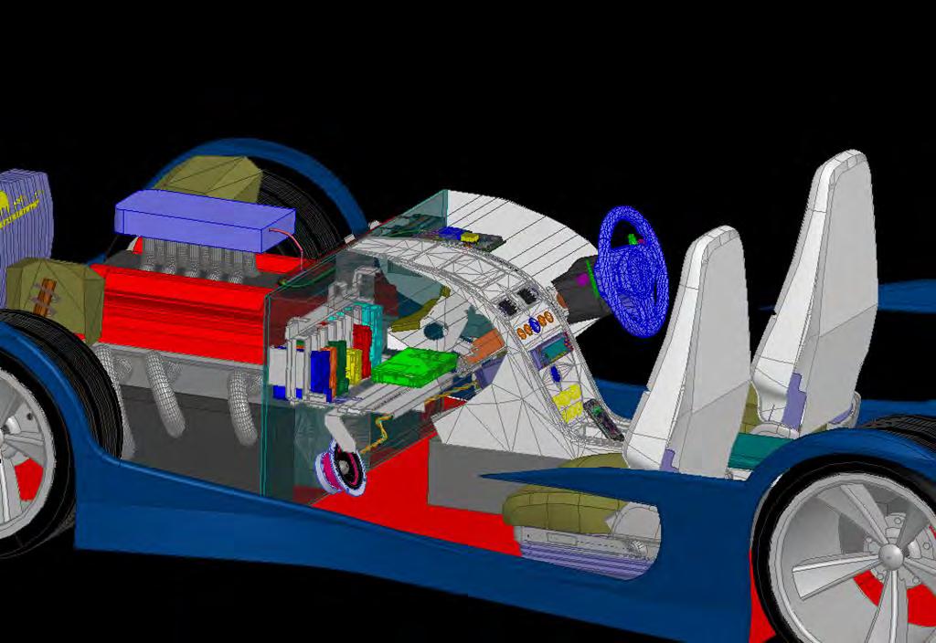
13 In-Vehicle GPS Reception A GPS telematics ECU receives the signal broadcasted by satellites at L1 frequency (1.575 GHz), calculates the actual position of the vehicle and send this information through a data network (usually an EDGE or GPRS network). How can we evaluate the GPS reception to chose the proper placement of the ECU? GPS Antenna GPS Telematics ECU 13


14 In-Vehicle GPS Reception Intuitively one can use a transient solver, having a incident plane wave coming from above, RHCP polarized at 1.575GHz, flowing normally towards the vehicle surface to simulate a GPS signal. The electric field can be visualized anywhere in time, showing the reflections due to vehicle s structures which will cause multipath and also the attenuation and phase shift. 14 Voltage on GPS Antenna


15 In-Vehicle GPS Reception A GPS signal is received by numerous incident angles. Transient analysis for numerous waves becomes very time consuming. One alternative is to use Radiation Efficiency by having the GPS antenna of the ECU transmitting a L1 signal instead of receiving. Radiation Efficiency is the ratio of the radiated power to the accepter power. Radiating Power is the amount of time-averaged power (in watts) exiting a radiating antenna structure through a radiation boundary (the lateral walls of the airbox). e=83% Airbox E-FIELD on airbox surfaces 15
16 In-Vehicle GPS Reception Radiation Efficiency can give us fast results in frequency domain indicating the best candidates for GPS antenna placement inside the vehicle. The example below shows a comparison between the ECU installed in the current position (position 1) and a new position (position 2) under the dashboard near the throttle. Near field plots are shown (3D polar plot and radiation pattern) as well as the radiation efficiency. 16


17 Automotive EMC Standards ISO Picture taken at INPE. Courtesy of Volvo Brasil. 17


18 ISO Automotive EMC Standards ISO The international standard ISO is applied to road vehicles and describes a vehicle test methods for electrical disturbances from narrowband radiated electromagnetic energy. It determines the immunity of passenger cars and commercial vehicles to electrical disturbances from off-vehicle radiation sources, regardless of the vehicle propulsion system. It can also be readily applied to other types of vehicles including hybrid electric vehicles (HEV). The test should be performed in an absorber-lined shielded enclosure, trying to create an indoor electromagnetic compatibility testing facility that simulates open field testing. Work Developed by FIAT Brazil (FIASA) 18


19 Automotive EMC Standards ISO WIRING HARNESS The antenna illuminates the vehicle and two simulations are performed: 1- The ECU is placed inside the vehicle without wiring harness and a clock signal is applied to the connector and goes to the uprocessor through a PCB trace. 2-The same ECU is now connected to the wiring harness and the same clock signal is now applied to the end of the harness near the motor that is connected to the ECU through the connector. CLK SIGNAL SIGNAL? 19
20 Automotive EMC Standards ISO This simulation shows that when the ECU is connected to the wiring harness the EMI is higher for a given bandwidth. Bit Error Rate (BER) for 165MHz is 1E-3 when the ECU is connected to the cable harness and it is 1E-17 when there is no cables and the clock is applied directly to the connector 20


21 Full Vehicle EMC tests PAPER Domain Decomposition Method HPC High Performance Computing DOMAIN DECOMPOSITION TECHNIQUE ENABLES THE SIMULATION OF VERY LARGE FIELD PROBLEMS BY SHARING THE ORIGINAL MESH INTO SUB DOMAINS USING PARALLEL PROCESSING COMPUTING 21

22 Full Vehicle EMC tests PAPER Domain Decomposition Method COMPUTATIONAL EFFORT 22


23 Full Vehicle EMC tests PAPER FEBI Finite Element Boundary Integral DDM IE FEM FEBI FEM 23


24 Full Vehicle EMC tests PAPER FEBI Finite Element Boundary Integral 310 min and 75 GB RAM 28 min and 6.8 GB RAM 24
 with")

25 EMC ON AUTOMOTIVE COMPONENTS Printed circuit board (PCB) with multiple package chips Chip (IC) Package PCB MCU: Chip inside wire-bond package 25

26 EMC ON AUTOMOTIVE COMPONENTS Increasing Accuracy through Chip Power Model - CPM Traditional Model Apache CPM Chip Parasitics Chip Current Single Lumped Model 26


 Package Chip Power Model (RedHawk-CPM) Package Parasitic Model")

27 EMC ON AUTOMOTIVE COMPONENTS Operation of safety (airbag) and infotainment systems depend on MCU speed Operating speed of MCU depends on quality of power supply it receives Poor PCB design can cause 100+mV drop Can reduce MCU performance by more than 40-60MHz Must design PCB considering MCU and impact on its performance Chip (IC) Package Chip Power Model (RedHawk-CPM) Package Parasitic Model (SIwave) PCB Parasitic Model (SIwave) V PCB Yellow ~ voltage at MCU with pkg/pcb Red ~ voltage at MCU/pkg but no PCB -100+mV drop from PCB - MCU speed lower by 40MHz 27

28 EMC ON AUTOMOTIVE COMPONENTS Project Development Phase Currently EMI checks done here only EMI needs to be improved in all of above levels 28
![EMC ON AUTOMOTIVE COMPONENTS Chip Package System Example J3 Voltage [db V]](/docs-images/71/65971690/images/29-4.jpg "The proposed simulation framework allows to predict the true post-silicon EMC")

29 EMC ON AUTOMOTIVE COMPONENTS Chip Package System Example J3 Voltage [db V] The proposed simulation framework allows to predict the true post-silicon EMC behavior vs. increasingly aggressive EMC targets dictated by marketing, customers, and international standards Frequency [Hz] Dr. Davide Pandini, ST Agrate 29


30 CISPR25 STANDARD 30


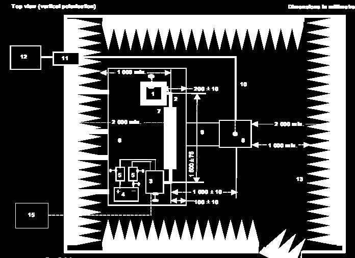
31 CISPR25 - RADIATED EMISSIONS An entire anechoic chamber can be simulated, including the absorber elements, DUT, antennas and the complete environment. This chamber can be used for simulating radiated emissions and immunity analysis. 31
32 CISPR25 - RADIATED EMISSIONS RADIATED EMISSIONS In this example the radiated emissions (Quasi Peak detector) are captured by the biconical antenna for every angular position of the DUT. PCB MODEL COURTESY OF 32


33 CISPR25 Radiated Emissions MEASUREMENT 3 meter sphere Simulated results show very good agreement with measurements HFSS SIMULATION (FEBI) 33

34 Physical Optics Solver Far Field Data Bigger environments can be simulated using different solvers. This example uses the Far Field data of a FEM antenna array model as a source to a bigger model solved using Physical Optics FEM Physical Optics Solver 34


35 Physical Optics Solver Physical Optics solver gives fast results of Far Fields by approximating the current density on surfaces and considering J equals to zero in shadow regions. No S-Matrix though FEM Far Field Data PHYSICAL OPTICS SOLVER 35


36 GSM Communication Using FEBI and IE Regions FEBI DOMAINS IE REGION S-Matrix can be calculated using FEBI and IE Regions. 36 INFINITE GND PLANE


37 GSM Communication Using FEBI and IE Regions AUDIO SYSTEM 37 CELL PHONE


38 GSM Communication Using FEBI and IE Regions The complete vehicle was simulated considering all geometries 38

39 GSM Communication Using FEBI and IE Regions We can couple the 3D HFSS model to ANSYS Designer and run a complete system level analysis of GSM communications. ANSYS Designer has complete libraries of system levels such as Wi-Fi, Bluetooth, WCDMA, GSM, etc Results including eye diagrams, frequency and time domain, BER can be plotted for the whole system. AUDIO TX1 AUDIO TX2 CELL CLK_IN AUDIO RX1 AUDIO RX2 CELL CLK_IN GSM IN GSM RX HFSS MODEL ECU IN1 ECU IN2 ECU RX1 ECU RX2 39

40 GSM Communication Using FEBI and IE Regions Rx EYE DIAGRAM GMSK SPECTRUM Tx EYE DIAGRAM Tx Time Domain Signal 40


41 GSM Communication Using FEBI and IE Regions We can also use signals measured on lab on our simulations. This case an actual song was used as excitation for our model and the EMI caused by GSM can be seen in time and frequency domain. MEASUREMENTS SIMULATION 41
42 Summary i. Simulation examples of antenna placement in vehicles and automotive EMC were shown using realistic models and Automotive Standards. ii. Electronics content in car are increasing exponentially and numerical simulation is required to reduce time to market and reduce costs through virtual prototyping. Simulation Driven Product Development. iii. Automotive EMC depends on every component, including chip level, so a Chip Package System (CPS) was presented allowing to predict the true post-silicon EMC behavior vs. increasingly aggressive EMC targets dictated by marketing, customers, and international standards. iv. Comparison between simulations vs. measurements has shown the effectiveness and the accuracy of ANSYS electromagnetic simulation tools. v. With the acquisition of APACHE, ANSYS provides a unique capability to accurately simulate EMC from Chip level up to a complete System Level fully integrating 3D full wave models with circuit/system solvers. 42
Aut omot i ve EMI / EMC Si mul at i ons Usi ng ANSYS Hi gh Fr equency Tool s. Markus Kopp Product Manager, Electronics ANSYS, Inc.
 Aut omot i ve EMI / EMC Si mul at i ons Usi ng ANSYS Hi gh Fr equency Tool s 1 ANSYS, Inc. September 21, Markus Kopp Product Manager, Electronics ANSYS, Inc. System Engineering ISO/IEC15288:2008: "A combination
HFSS 13: Hybrid FE-BI for Efficient Simulation of Radiation and Scattering David Edgar Senior Application Engineer ANSYS Inc.
 HFSS 13: Hybrid FE-BI for Efficient Simulation of Radiation and Scattering David Edgar Senior Application Engineer ANSYS Inc. 2011 ANSYS, Inc. All rights reserved. 1 ANSYS, Inc. Proprietary Agenda FEM
Nonlinear Effects in Active Phased Array System Performance
 Nonlinear Effects in Active Phased Array System Performance Larry Williams, PhD Director of Product Management ANSYS Inc. 1 Advanced Simulation Simulate the Complete Product Real-life behavior in real-world
Highly Accurate and Robust Automotive Radar System Design. Markus Kopp Lead Application Specialist ANSYS Inc.
 Highly Accurate and Robust Automotive Radar System Design Markus Kopp Lead Application Specialist ANSYS Inc. Introduction This presentation is an overview of a proposed design methodology for automotive
ANSYS CPS SOLUTION FOR SIGNAL AND POWER INTEGRITY
 ANSYS CPS SOLUTION FOR SIGNAL AND POWER INTEGRITY Rémy FERNANDES Lead Application Engineer ANSYS 1 2018 ANSYS, Inc. February 2, 2018 ANSYS ANSYS - Engineering simulation software leader Our industry reach
Investigation of Electromagnetic Field Coupling from DC-DC Buck Converters to Automobile AM/FM Antennas
 CST North American Automotive Workshop Investigation of Electromagnetic Field Coupling from DC-DC Buck Converters to Automobile AM/FM Antennas Patrick DeRoy, CST of America, Framingham, Massachusetts,
EMI Reduction on an Automotive Microcontroller
 EMI Reduction on an Automotive Microcontroller Design Automation Conference, July 26 th -31 st, 2009 Patrice JOUBERT DORIOL 1, Yamarita VILLAVICENCIO 2, Cristiano FORZAN 1, Mario ROTIGNI 1, Giovanni GRAZIOSI
Test and Measurement for EMC
 Test and Measurement for EMC Bogdan Adamczyk, Ph.D., in.c.e. Professor of Engineering Director of the Electromagnetic Compatibility Center Grand Valley State University, Michigan, USA Ottawa, Canada July
Lecture 8: Introduction to Hybrid FEM IE
 Lecture 8: Introduction to Hybrid FEM IE 2015.0 Release ANSYS HFSS for Antenna Design 1 2015 ANSYS, Inc. Hybrid FEM-IE Solution Using HFSS and HFSS-IE Advantages of Hybrid Solution Leverage the strength
EMI. Chris Herrick. Applications Engineer
 Fundamentals of EMI Chris Herrick Ansoft Applications Engineer Three Basic Elements of EMC Conduction Coupling process EMI source Emission Space & Field Conductive Capacitive Inductive Radiative Low, Middle
High-Performance Electronic Design: Predicting Electromagnetic Interference
 White Paper High-Performance Electronic Design: In designing electronics in today s highly competitive markets, meeting requirements for electromagnetic compatibility (EMC) presents a major risk factor,
EMC cases study. Antonio Ciccomancini Scogna, CST of America CST COMPUTER SIMULATION TECHNOLOGY
 EMC cases study Antonio Ciccomancini Scogna, CST of America antonio.ciccomancini@cst.com Introduction Legal Compliance with EMC Standards without compliance products can not be released to the market Failure
Prediction of Co-site interference in complex RF environments
 Prediction of Co-site interference in complex RF environments Frank Demming-Janssen CST AG The Cosite Scenario Multiple RF systems co-located in a common environment Diverse system characteristics Frequency
CHAPTER 6 EMI EMC MEASUREMENTS AND STANDARDS FOR TRACKED VEHICLES (MIL APPLICATION)
") 147 CHAPTER 6 EMI EMC MEASUREMENTS AND STANDARDS FOR TRACKED VEHICLES (MIL APPLICATION) 6.1 INTRODUCTION The electrical and electronic devices, circuits and systems are capable of emitting the electromagnetic
147 CHAPTER 6 EMI EMC MEASUREMENTS AND STANDARDS FOR TRACKED VEHICLES (MIL APPLICATION) 6.1 INTRODUCTION The electrical and electronic devices, circuits and systems are capable of emitting the electromagnetic
L.S. Compliance, Inc. W66 N220 Commerce Court Cedarburg, WI
 L.S. Compliance, Inc. W66 N220 Commerce Court Cedarburg, WI 53012 262-375-4400 COMPLIANCE TESTING OF: Quartex Synchronization Transmitter Model FM-72 PREPARED FOR: Quartex, Division of Primex, Inc. 965
Verifying Simulation Results with Measurements. Scott Piper General Motors
 Verifying Simulation Results with Measurements Scott Piper General Motors EM Simulation Software Can be easy to justify the purchase of software packages even costing tens of thousands of dollars Upper
EMI/EMC of Entire Automotive Vehicles and Critical PCB s. Makoto Suzuki Ansoft Corporation
 EMI/EMC of Entire Automotive Vehicles and Critical PCB s Makoto Suzuki Ansoft Corporation WT10_SI EMI/EMC of Entire Automotive Vehicles and Critical PCB s Akira Ohta, Toru Watanabe, Benson Wei Makoto Suzuki
Comparative Analysis of Intel Pentium 4 and IEEE/EMC TC-9/ACEM CPU Heat Sinks
 Comparative Analysis of Intel Pentium 4 and IEEE/EMC TC-9/ACEM CPU Heat Sinks Author Lu, Junwei, Duan, Xiao Published 2007 Conference Title 2007 IEEE International Symposium on Electromagnetic Compatibility
Large E Field Generators in Semi-anechoic Chambers for Full Vehicle Immunity Testing
 Large E Field Generators in Semi-anechoic Chambers for Full Vehicle Immunity Testing Vince Rodriguez ETS-Lindgren, Inc. Abstract Several standards recommend the use of transmission line systems (TLS) as
Facility Grounding & Bonding Based on the EMC/PI/SI Model for a High Speed PCB/Cabinet
 Facility Grounding & Bonding Based on the EMC/PI/SI Model for a High Speed PCB/Cabinet and: SILICON LABS AN203 PRINTED CIRCUIT BOARD DESIGN NOTES www.silabs.com William Bush (wbush@ieee.org) Industry Consultant
Co-site interference analysis. Marli Strydom CST AG
 Co-site interference analysis Marli Strydom CST AG The Cosite Scenario Victim Rx trying to hear desired signal from remote Tx At the same time, local emitters are transmitting Emitters can interfere with
Course Introduction. Content 16 pages. Learning Time 30 minutes
 Course Introduction Purpose This course discusses techniques for analyzing and eliminating noise in microcontroller (MCU) and microprocessor (MPU) based embedded systems. Objectives Learn what EMI is and
Normalized Site Attenuation Test Report
 NVLAP LAB CODE 200974-0 Normalized Site Attenuation Test Report Test Specification NORMALIZED SITE ATTENUATION (NSA) Range 30 MHz 1GHz using the methods of ANSI C63.4-2009; EN 50147-2 (1997); CISPR 16-1-4
Design for Guaranteed EMC Compliance
 Clemson Vehicular Electronics Laboratory Reliable Automotive Electronics Automotive EMC Workshop April 29, 2013 Design for Guaranteed EMC Compliance Todd Hubing Clemson University EMC Requirements and
Electromagnetic Compatibility
 Electromagnetic Compatibility Introduction to EMC International Standards Measurement Setups Emissions Applications for Switch-Mode Power Supplies Filters 1 What is EMC? A system is electromagnetic compatible
UL Japan, Inc. Head Office EMC Lab Asama-cho, Ise-shi, Mie-ken JAPAN Telephone : Facsimile :
 Page : 2 of 19 CONTENTS PAGE SECTION 1: Client information... 3 SECTION 2: Equipment under test (E.U.T.)... 3 SECTION 3: Test specification, procedures & results... 5 SECTION 4: Operation of E.U.T. during
IEEE RTPGE Automotive Datalinks over Twisted Quad Cabling
 Automotive Datalinks over Twisted Quad Cabling T. Müller, G. Armbrecht, S. Kunz Rosenberger Hochfrequenztechnik GmbH & Co. KG Outline Automotive Datalinks over Twisted Quad Cabling Twisted Quad fundamentals
Preliminary Design and Development of Open Field Antenna Test Site
 Preliminary Design and Development of Open Field Antenna Test Site A. Ignatius Agung Wibowo 1, *,B. Mohammad Zarar Mohamed Jenu 1 and C. Alireza Kazemipour 1 1 Faculty of Electrical & Electronic Engineering,
Test Results #TR 4012, v1.0
 ITT Industries, Electronic Components/X2Y Attenuators Case Study of Filtered Connector Application in Blower Motor to Meet EMC Requirements Test Results #TR 4012, v1.0 DISCLAIMER: Information and suggestions
AUTOMOTIVE ELECTROMAGNETIC COMPATIBILITY (EMC)
") AUTOMOTIVE ELECTROMAGNETIC COMPATIBILITY (EMC) AUTOMOTIVE ELECTROMAGNETIC COMPATIBILITY (EMC) Terence Rybak Mark Steffka KLUWER ACADEMIC PUBLISHERS NEW YORK, BOSTON, DORDRECHT, LONDON, MOSCOW ebook ISBN:
AUTOMOTIVE ELECTROMAGNETIC COMPATIBILITY (EMC) AUTOMOTIVE ELECTROMAGNETIC COMPATIBILITY (EMC) Terence Rybak Mark Steffka KLUWER ACADEMIC PUBLISHERS NEW YORK, BOSTON, DORDRECHT, LONDON, MOSCOW ebook ISBN:
Todd Hubing. Clemson University. Cabin Environment Communication System. Controls Airbag Entertainment Systems Deployment
 Automotive Component Measurements for Determining Vehicle-Level Radiated Emissions Todd Hubing Michelin Professor of Vehicular Electronics Clemson University Automobiles are Complex Electronic Systems
Course Introduction Purpose Objectives Content Learning Time
 Course Introduction Purpose This course discusses techniques for analyzing and eliminating noise in microcontroller (MCU) and microprocessor (MPU) based embedded systems. Objectives Learn about a method
Design and Matching of a 60-GHz Printed Antenna
 Application Example Design and Matching of a 60-GHz Printed Antenna Using NI AWR Software and AWR Connected for Optenni Figure 1: Patch antenna performance. Impedance matching of high-frequency components
Heat sink. Insulator. µp Package. Heatsink is shown with parasitic coupling.
 X2Y Heatsink EMI Reduction Solution Summary Many OEM s have EMI problems caused by fast switching gates of IC devices. For end products sold to consumers, products must meet FCC Class B regulations for
EM Simulation of Automotive Radar Mounted in Vehicle Bumper
 EM Simulation of Automotive Radar Mounted in Vehicle Bumper Abstract Trends in automotive safety are pushing radar systems to higher levels of accuracy and reliable target identification for blind spot
REVERBERATION CHAMBER FOR EMI TESTING
 1 REVERBERATION CHAMBER FOR EMI TESTING INTRODUCTION EMI Testing 1. Whether a product is intended for military, industrial, commercial or residential use, while it must perform its intended function in
Todd H. Hubing Michelin Professor of Vehicular Electronics Clemson University
 Essential New Tools for EMC Diagnostics and Testing Todd H. Hubing Michelin Professor of Vehicular Electronics Clemson University Where is Clemson University? Clemson, South Carolina, USA Santa Clara Valley
EMC Simulation of Consumer Electronic Devices
 of Consumer Electronic Devices By Andreas Barchanski Describing a workflow for the EMC simulation of a wireless router, using techniques that can be applied to a wide range of consumer electronic devices.
GTEM cell simplifies EMC test
 GTEM cell simplifies EMC test Check the EMC performance of your designs in the lab with a GTEM cell and a spectrum analyzer. James P. Muccioli, Jastech EMC Consulting, Farmington Hills, MI Anthony A. Anthony
Demo / Application Guide for DSA815(-TG) / DSA1000 Series
 / DSA1000 Series") Demo / Application Guide for DSA815(-TG) / DSA1000 Series TX1000 Mobile Phone Frontend Mixer Bandpass Filter PA The schematic above shows a typical front end of a mobile phone. Our TX1000 RF Demo Kit shows
Demo / Application Guide for DSA815(-TG) / DSA1000 Series TX1000 Mobile Phone Frontend Mixer Bandpass Filter PA The schematic above shows a typical front end of a mobile phone. Our TX1000 RF Demo Kit shows
Ave output power ANT 1(dBm) Ave output power ANT 2 (dbm)
 Ave output power ANT 2 (dbm)") Page 41 of 103 9.6. Test Result The test was performed with 802.11b Channel Frequency (MHz) power ANT 1(dBm) power ANT 2 (dbm) power ANT 1(mW) power ANT 2 (mw) Limits dbm / W Low 2412 7.20 7.37 5.248 5.458
Page 41 of 103 9.6. Test Result The test was performed with 802.11b Channel Frequency (MHz) power ANT 1(dBm) power ANT 2 (dbm) power ANT 1(mW) power ANT 2 (mw) Limits dbm / W Low 2412 7.20 7.37 5.248 5.458
RF Emissions Test Report To Determine Compliance With: FCC, Part 15 Rules and Regulations
 RF Emissions Test Report To Determine Compliance With: FCC, Part 15 Rules and Regulations Model numbers: HT130022 Rev. B. December 17, 2002 Manufacturer: HQ, Inc. 210 9th Steet Drive Palmetto, FL 34221
Sunlight Supply, Inc.
 FCC Part 18 Subpart C Non-Consumer For RF Lighting Equipment Electromagnetic Compatibility Test Report Sunlight Supply, Inc. Commercial Ballast 1000 Watt - July 18, 2017 Tests Conducted by:, LLC 20811
Automotive EMC. IEEE EMC Society Melbourne Chapter October 13, 2010 By Mark Steffka IEEE EMCS Distinguished Lecturer
 Automotive EMC IEEE EMC Society Melbourne Chapter October 13, 2010 By Mark Steffka IEEE EMCS Distinguished Lecturer Email: msteffka@ieee.org IEEE 1 Automotive Systems Past and Present Today s vehicles
Research on Electromagnetic Compatibility of New Energy Vehicles
 2017 4th International Conference on Vehicle, Mechanical and Electrical Engineering (ICVMEE 2017) ISBN: 978-1-60595-477-6 Research on Electromagnetic Compatibility of New Energy Vehicles YUE ZHANG, XU
Saturation of Active Loop Antennas
 Saturation of Active Loop Antennas Alexander Kriz EMC and Optics Seibersdorf Laboratories 2444 Seibersdorf, Austria Abstract The EMC community is working towards shorter test distances for radiated emission
Automotive Systems Past and Present
 Automotive EMC IEEE EMC Society Eastern North Carolina Section February 9, 2010 By Mark Steffka IEEE EMCS Distinguished Lecturer Email: msteffka@ieee.org IEEE 1 Automotive Systems Past and Present Today
Broadband Antenna FDTD Modeling for EMC Test
 Broadband Antenna FDTD Modeling for EMC Test R. Jauregui, M. A. Heras and F. Silva Grup de Compatibilitat Electromagnètica (GCEM),Departament d Enginyeria Electrònica (DEE), Universitat Politècnica de
Antenna Simulation Overview
 Antenna Simulation Overview Marc Rütschlin, Senior Application Engineer 2011 CST European UGM 18-19 May 2011 1 Antenna Choice Analysis Optimisation Environment Antenna Design Flow 2011 CST European UGM
NUMERICAL METHODOLOGY FOR THE EMI RISK ASSESSMENT OF VEHICULAR ANTENNAS
 NUMERICAL METHODOLOGY FOR THE EMI RISK ASSESSMENT OF VEHICULAR ANTENNAS Alberto Buttiglieri EMEA Product Development Electrical Electronics Unit Audio & Telematics Darmstadt, Germany Content Automotive
Investig&ion of the Theoretical Basis for Using a 1 G& TEM Cell to Evaluate the Radiated Emissions from Integrated Circuits
 Investig&ion of the Theoretical Basis for Using a 1 G& TEM Cell to Evaluate the Radiated Emissions from Integrated Circuits James P. Muccioli JASTECH P.O. Box 3332 Farmington Hills, MI 48333 Terty M. North
NSA Calculation of Anechoic Chamber Using Method of Moment
 200 Progress In Electromagnetics Research Symposium 2006, Cambridge, USA, March 26-29 NSA Calculation of Anechoic Chamber Using Method of Moment T. Sasaki, Y. Watanabe, and M. Tokuda Musashi Institute
EMI Modeling of a 32-bit Microcontroller in Wait Mode
 EMI Modeling of a 32-bit Microcontroller in Wait Mode Jean-Pierre Leca 1,2, Nicolas Froidevaux 1, Henri Braquet 2, Gilles Jacquemod 2 1 STMicroelectronics, 2 LEAT, UMR CNRS-UNS 6071 BMAS 2010 San Jose,
Calibration and Validation for Automotive EMC
 Calibration and Validation for Automotive EMC Wolfgang Müllner Patrick Preiner Alexander Kriz Seibersdorf Labor GmbH 2444 Seibersdorf, Austria http://rf.seibersdorf-laboratories.at rf@seibersdorf-laboratories.at
Realize Your Product Promise. Maxwell
 Realize Your Product Promise Maxwell DC permanent magnet motor solved by Maxwell with ANSYS RMxprt Build reliability and efficiency into your electromagnetic and electromechanical designs with ANSYS Maxwell.
 1.0 Job Description 1.1 Client Information This EUT has been tested at the request of: Company: Spectronic Denmark A/S Contact: John Herlev Telephone: 011 45 863-87-222 Fax: 011 45 863-87-704 Email: jhe@spectronic-denmark.com
A Study of Conducted-Emission Stable Source Applied to the EMC US and EU Standards
 Fourth LACCEI International Latin American and Caribbean Conference for Engineering and Technology (LACCEI 2006) Breaking Frontiers and Barriers in Engineering: Education, Research and Practice, 21-23
Combining Differential/Integral Methods and Time/Frequency Domain Analysis to Solve Complex Antenna Problems
 Combining Differential/Integral Methods and Time/Frequency Domain Analysis to Solve Complex Antenna Problems IEEE Long Island Section MTT-S Jan. 27, 20 Overview of Presentation Antenna design challenges
TEST REPORT: ELECTROMAGNETIC COMPATIBILITY - ESA Regulation Consolidated to Supplement 2 (Revision 4 Amendment 2)
") Vehicle Certification Agency, 1 The Eastgate Office Centre Eastgate Road, Bristol, BS5 6XX, United Kingdom. Telephone: +44 (0) 117 951 5151 Fax: +44 (0) 117 952 4103 Email: enquiries@vca.gov.uk www.dft.gov.uk/vca
Vehicle Certification Agency, 1 The Eastgate Office Centre Eastgate Road, Bristol, BS5 6XX, United Kingdom. Telephone: +44 (0) 117 951 5151 Fax: +44 (0) 117 952 4103 Email: enquiries@vca.gov.uk www.dft.gov.uk/vca
Relationship Between Signal Integrity and EMC
 Relationship Between Signal Integrity and EMC Presented by Hasnain Syed Solectron USA, Inc. RTP, North Carolina Email: HasnainSyed@solectron.com 06/05/2007 Hasnain Syed 1 What is Signal Integrity (SI)?
Unclassified Distribution A: Unlimited Public Release
 IMPACT OF INADVERTENT ELECTROMAGNETIC EMISSIONS ON ORGANIC VEHICLES THAT AFFECT THE TACTICAL COMMUNICATIONS OPERATING BANDS By Erick Ortiz and Frank A. Bohn US ARMY CERDEC Antennas & Spectrum Analysis
This document is a preview generated by EVS
 INTERNATIONAL STANDARD ISO 11452-9 First edition 2012-05-15 Road vehicles Component test methods for electrical disturbances from narrowband radiated electromagnetic energy Part 9: Portable transmitters
The Association of Loudspeaker Manufacturers & Acoustics International presents. Dr. David R. Burd
 The Association of Loudspeaker Manufacturers & Acoustics International presents Dr. David R. Burd Manager of Engineering and Technical Support Free Field Technologies an MSC Company Tutorial Actran for
5G Antenna Design for Mobile Phones
 3DS.COM Dassault Systèmes 11/30/2018 ref.: 3DS_Document_2015 5G Antenna Design for Mobile Phones 29 November 2018, 17h00 CET Marc Rütschlin marc.ruetschlin@3ds.com Rodrigo Enjiu, Brian Woods, Marcel Plonka,
Electromagnetic Compliance: Pre-Compliance Test Basics October 19, 2017
 Electromagnetic Compliance: Pre-Compliance Test Basics October 19, 2017 Today s products are subjected to more standardized test requirements than ever before. These standards (UL, CE, and others) ensure
Full Wave Solution for Intel CPU With a Heat Sink for EMC Investigations
 Full Wave Solution for Intel CPU With a Heat Sink for EMC Investigations Author Lu, Junwei, Zhu, Boyuan, Thiel, David Published 2010 Journal Title I E E E Transactions on Magnetics DOI https://doi.org/10.1109/tmag.2010.2044483
Modeling and Simulation of Powertrains for Electric and Hybrid Vehicles
 Modeling and Simulation of Powertrains for Electric and Hybrid Vehicles Dr. Marco KLINGLER PSA Peugeot Citroën Vélizy-Villacoublay, FRANCE marco.klingler@mpsa.com FR-AM-5 Background The automotive context
EMDS for ADS Momentum
 EMDS for ADS Momentum ADS User Group Meeting 2009, Böblingen, Germany Prof. Dr.-Ing. Frank Gustrau Gustrau, Dortmund User Group Meeting 2009-1 Univ. of Applied Sciences and Arts (FH Dortmund) Presentation
INTERNATIONAL STANDARD
 INTERNATIONAL STANDARD ISO 11452-7 Second edition 2003-11-15 Road vehicles Component test methods for electrical disturbances from narrowband radiated electromagnetic energy Part 7: Direct radio frequency
Heat Sink Design Flow for EMC
 DesignCon 2008 Heat Sink Design Flow for EMC Philippe Sochoux, Cisco Systems, Inc. psochoux@cisco.com Jinghan Yu, Cisco Systems, Inc. jinyu@cisco.com Alpesh U. Bhobe, Cisco Systems, Inc. abhobe@cisco.com
150Hz to 1MHz magnetic field coupling to a typical shielded cable above a ground plane configuration
 150Hz to 1MHz magnetic field coupling to a typical shielded cable above a ground plane configuration D. A. Weston Lowfreqcablecoupling.doc 7-9-2005 The data and information contained within this report
Design Considerations for Highly Integrated 3D SiP for Mobile Applications
 Design Considerations for Highly Integrated 3D SiP for Mobile Applications FDIP, CA October 26, 2008 Joungho Kim at KAIST joungho@ee.kaist.ac.kr http://tera.kaist.ac.kr Contents I. Market and future direction
EMC Evaluation at Green Bank: Emissions and Shield Effectiveness
 EMC Evaluation at Green Bank: Emissions and Shield Effectiveness National Radio Astronomy Observatory Carla Beaudet Green Bank RFI Group Leader Emissions Evaluation: Standards ITU-R RA.769 specifies (typical)
EMC review for Belle II (Grounding & shielding plans) PXD DEPFET system
 PXD DEPFET system") EMC review for Belle II (Grounding & shielding plans) PXD DEPFET system Outline 1. Introduction 2. Grounding strategy Implementation aspects 3. Noise emission issues Test plans 4. Noise immunity issues
EMC review for Belle II (Grounding & shielding plans) PXD DEPFET system Outline 1. Introduction 2. Grounding strategy Implementation aspects 3. Noise emission issues Test plans 4. Noise immunity issues
EM Noise Mitigation in Electronic Circuit Boards and Enclosures
 EM Noise Mitigation in Electronic Circuit Boards and Enclosures Omar M. Ramahi, Lin Li, Xin Wu, Vijaya Chebolu, Vinay Subramanian, Telesphor Kamgaing, Tom Antonsen, Ed Ott, and Steve Anlage A. James Clark
Automotive EMI/EMC Pre-compliance Tests
 Automotive EMI/EMC Pre-compliance Tests Introduction Electromagnetic interference (EMI) regulations are in place throughout the world to provide improved reliability and safety for users of electrical
of sound radiation from electric motors
 Titelmasterformat Mid-frequency challenge durch Klicken efficient bearbeiten simulation of sound radiation from electric motors M. Moosrainer, M. Jegham, CADFEM GmbH 19.03.2018, DAGA 2018 Munich ANSYS
High Frequency Structure Simulator (HFSS) Tutorial
 Tutorial") High Frequency Structure Simulator (HFSS) Tutorial Prepared by Dr. Otman El Mrabet IETR, UMR CNRS 6164, INSA, 20 avenue Butte des Coësmes 35043 Rennes, FRANCE 2005-2006 TABLE OF CONTENTS INTRODUCTION...
High Frequency Structure Simulator (HFSS) Tutorial Prepared by Dr. Otman El Mrabet IETR, UMR CNRS 6164, INSA, 20 avenue Butte des Coësmes 35043 Rennes, FRANCE 2005-2006 TABLE OF CONTENTS INTRODUCTION...
TEST REPORT FROM RADIO FREQUENCY INVESTIGATION LTD.
 TEST REPORT FROM RADIO FREQUENCY INVESTIGATION LTD. Test Of: Wood & Douglas Ltd ST500 Transmitter Test Report Serial No: RFI/EMCB2/RP39403B This Test Report supersedes RFI Test Report No.: RFI/EMCB1/RP39403B
Test sites for EMC measurements
 Test sites for EMC measurements EMV Fachtagung 21. Januar 2014 Christophe Perrenoud www.montenaemc.ch montena emc Route de Montena 75 CH - 1728 Rossens Tel. +41 26 411 93 33 Fax +41 26 411 93 30 office.emc@montenaemc.ch
EMC aspects associated to 5G networks
 EMC aspects associated to 5G networks ETSI TC-EE/ITU-T SG5 Workshop on Towards Setting Environmental Requirements for 5G Beniamino Gorini 23-11-2017 1 Outline 1. Scenario of present EMC requirements 2.
An Introduction to FFT EMI Receivers
 An Introduction to FFT EMI Receivers Introduction An evolution in EMI receiver design is underway to take advantage of today s digital signal processing (DSP) technologies, using fast Fourier transform
EMC simulation addresses ECU validation issues
 EMC simulation addresses ECU validation issues A more straightforward validation of electromagnetic compatibility can be achieved by combining tools. By Stefan Heimburger, Andreas Barchanski, and Thorsten
LTE Band 7. Channel
 Bandwidth 5MHz Frequency (MHz) LTE Band 7 Bandwidth 10MHz Peak To Average Ratio (db) Frequency Peak To Average Ratio (db) QPSK 16QAM (MHz) QPSK 16QAM 20775 2502.5 3.57 4.34 20800 2505 3.51 4.28 21100 2535
Measurement of RF Emissions from a Caterpillar Inc. MSS3s RF ID Key Fob
 Measurement of RF Emissions from a Caterpillar Inc. MSS3s RF ID Key Fob For Caterpillar Inc. 330 S.W. Adams Street Peoria, IL 61630 P.O. Number JBL 11260 Date Tested May 11, 2016 Test Personnel Mark Longinotti
Test Report No
 x Test Report No.8312314587 For Synel Industries Ltd. Equipment Under Test: Proximity Reader From The Standards Institution Of Israel Industry Division Telematics Laboratory EMC Section Certificate No.
Introduction to Electromagnetic Compatibility
 Introduction to Electromagnetic Compatibility Second Edition CLAYTON R. PAUL Department of Electrical and Computer Engineering, School of Engineering, Mercer University, Macon, Georgia and Emeritus Professor
SPECIFICATION. Part No. : MA1060.A.LBCT.001
 SPECIFICATION Part No. : MA1060.A.LBCT.001 Product Name : Raptor I MA1060 Sharkfin 4in1 Next Generation Permanent Mount External Antenna with LTE, GNSS, Wi-Fi and AM/FM Features : High Efficiency Omnidirectional
Novel Modeling Strategy for a BCI set-up applied in an Automotive Application
 Novel Modeling Strategy for a BCI set-up applied in an Automotive Application An industrial way to use EM simulation tools to help Hardware and ASIC designers to improve their designs for immunity tests.
CHARACTERISATION OF IN -HOUSE EMC TESTING FACILITIES FOR PRODUCT DESIGNERS. Paul Kay* and Andrew Nafalski**
 CHARACTERISATION OF IN -HOUSE EMC TESTING FACILITIES FOR PRODUCT DESIGNERS Paul Kay* and Andrew Nafalski** *Austest Laboratories, Adelaide **University of South Australia School of Electrical and Information
OPEN TEM CELLS FOR EMC PRE-COMPLIANCE TESTING
 1 Introduction Radiated emission tests are typically carried out in anechoic chambers, using antennas to pick up the radiated signals. Due to bandwidth limitations, several antennas are required to cover
ENGINEERING TEST REPORT # C LSR Job #: C-2411 Compliance Testing of: RM186-SM
 W66 N220 Commerce Court Cedarburg, WI 53012 USA Phone: 262.375.4400 Fax: 262.375.4248 www.lsr.com ENGINEERING TEST REPORT # 316062C LSR Job #: C-2411 Compliance Testing of: RM186-SM Test Date(s): 3-28-16
IEEE Electromagnetic Compatibility Standards (Active & Archive) Collection: VuSpec
 Collection: VuSpec") IEEE Electromagnetic Compatibility Standards (Active & Archive) Collection: VuSpec This value-packed VuSpec represents the most complete resource available for professional engineers looking for best practices
IEEE Electromagnetic Compatibility Standards (Active & Archive) Collection: VuSpec This value-packed VuSpec represents the most complete resource available for professional engineers looking for best practices
Specification. Patent Pending. Description : AccuraUWB Flex Series 3~10GHz Ultra-Wide Band (UWB) Flex Antenna with 100mm 1.
 Flex Antenna with 100mm 1.") Specification Patent Pending Part No. : FXUWB10.07.0100C Description : AccuraUWB Flex Series 3~10GHz Ultra-Wide Band (UWB) Flex Antenna with 100mm 1.37mm IPEX MHFHT Features : Flexible UWB Antenna Mounting
Specification Patent Pending Part No. : FXUWB10.07.0100C Description : AccuraUWB Flex Series 3~10GHz Ultra-Wide Band (UWB) Flex Antenna with 100mm 1.37mm IPEX MHFHT Features : Flexible UWB Antenna Mounting
Influence of Termination Impedance on conducted Emissions in Automotive High Voltage Networks
 Influence of Termination Impedance on conducted Emissions in Automotive High Voltage Networks M. Reuter *, S. Tenbohlen, W. Koehler Institute of Power Transmission and High Voltage Technology (IEH), University
OPEN TEM CELLS FOR EMC PRE-COMPLIANCE TESTING
 1 Introduction Radiated emission tests are typically carried out in anechoic chambers, using antennas to pick up the radiated signals. Due to bandwidth limitations, several antennas are required to cover
Electromagnetic Compatibility Test Report
 Electromagnetic Compatibility Test Report Test Report No: SAE 140711 Issued on: July 14, 2011 Product Name Transceiver for Antenna Tag Identification Model: Ideal Atmega 358/200 khz Tested According to
Test specification: Section (e)(1), Radiated emissions below 40 GHz Test procedure: ANSI C63.4, Sections 8.3.2, 13.2, 13.4 Test mode: Compliance
(1), Radiated emissions below 40 GHz Test procedure: ANSI C63.4, Sections 8.3.2, 13.2, 13.4 Test mode: Compliance") Test specification: Section 15.253(e)(1), Radiated emissions below 40 GHz Test procedure: ANSI C63.4, Sections 8.3.2, 13.2, 13.4 Plot 7.2.7 Radiated emission measurements at frequency 7280 MHz Low channel
Test specification: Section 15.253(e)(1), Radiated emissions below 40 GHz Test procedure: ANSI C63.4, Sections 8.3.2, 13.2, 13.4 Plot 7.2.7 Radiated emission measurements at frequency 7280 MHz Low channel
ITG Electronics, Inc.
 Mitigating EMI Problems & Filter Selection By Rafik Stepanian EMI Noise Generators A change of state (On/Off ) in an Electronic component has the potential to generate EMI. Typical examples are Electronic
5G Antenna Design & Network Planning
 5G Antenna Design & Network Planning Challenges for 5G 5G Service and Scenario Requirements Massive growth in mobile data demand (1000x capacity) Higher data rates per user (10x) Massive growth of connected