Strategies for High Density and High Speed Packaging. Ride the Wave Workshop
|
|
|
- Patrick Gordon
- 6 years ago
- Views:
Transcription


1 Strategies for High Density and High Speed Packaging Ride the Wave Workshop
2 Topics! Trends in Packaging! Common Design Challenges! Design through Software! Supply Plane Analysis with SIwave! Non-ideal Power/Ground Planes! Plane Impedance vs. Frequency! Package Design Automation with TPA 4.0! Broadband BGA Characterization! Bit-Error Rate (BER) Testing for BGA! Design Rule Generation from Simulation! Demonstration SIwave and TPA 4.0! Summary
3 Trends in Packaging Intel Microprocessor Product Advancement Freq: GHz Bus: 100 MHz (400 MTS) Wire bond Technology Freq: 800 MHz GHz Bus: 200 MHz (400 MTS) Speed/Complexity PIV OLGA2/INT PIII - Celeron FCPGA1 Freq: MHz Bus: 66/100 MHz Mobile OLGA1/INT Freq: MHz Bus: 100/133 MHz IA64 - Itanium OLGA2/INT PIII SECC Slot 1 Freq: 500 MHz GHz Bus: 100/133 MHz Freq: MHz Bus: 100/133 MHz PIII - Xeon SECC Slot Package Area (mm 2 ) [1]
! Microball Grid Array (µbga)! Flip Chip!")
4 Trends in Packaging Speed and Topology Issues! Broadband Behavior Critical! Clock Frequencies Continue to Increase! Edge Rates in the Tens of ps Range! Package structures more tightly coupled! Minimum Line Width decreasing! Solderball and Wirebond Pitch decreasing! Wide Range of Packaging Choices to understand! Chip-Scale Packaging (CSP)! Microball Grid Array (µbga)! Flip Chip! Stacked Bare IC s


5 Trends in Packaging Packaging and its Effects on Circuits VCO design with package effects neglected! VCO in Ansoft Serenade! Oscillation Freq. of 520 MHz


6 Trends in Packaging Packaging and its Effects on Circuits VCO design with package effects included! VCO in Ansoft Serenade! Extracted Package Parasitics included from Q3D Extractor! Oscillation Disappears Oscillation disappears!!
7 Trends in Packaging Design Flow of the 90s IC Designer Package Designer Final Component! IC Design and Package Design are Critically Linked! Packaging Effects MUST be Considered During Design Process
8 Trends in Packaging Design Flow for the this Century IC Designer Final Component Package Designer! IC Designer and Package Designer need to work together for success! Packaging has become its own discipline
9 Common Design Challenges! Reflection Noise! Impedance Mismatch, Vias, Other Discontinuities! Crosstalk Noise! Electromagnetic coupling between traces and vias! Power/Ground Noise! Non-ideal planes cause parasitic effects! Commonly referred to as Ground Bounce, Delta- I Noise or Simultaneous Switching Noise (SSN)! High Frequency Effects! Radiation, Resonances, Dispersion
10 Common Design Challenges Understanding Through Simulation Packaging structures and their PCB s contain complex signal paths with many types of 2D and 3D discontinuities. Successful designs require a good understanding of the signal path and the power delivery system. Signal Path Landmines:! Connectors, Split Planes, Vias! Multiple Substrates, Dispersive Substrates! Solder Balls, Bond Pads, Bondwires, Solderbumps! Parallel Plate Modes
11 Common Design Challenges Understanding Through Simulation Effective designs for advanced packaging evolve from an understanding of the fundamental Electromagetics. A total package analysis solution consists of:! Industry Standard Layout/Design Tools! Effective Quasi-Static Simulation/Extraction for low speed characterization! Full-Wave Analysis for critical high bandwidth applications! Circuit and System level analysis to integrate the results of simulations. These tools will help reduce design cycle time and save money in prototyping costs.

! TPA! Full-Wave!")

12 Common Design Challenges Methods Available for Simulation! Packaging simulation requires careful consideration of application needs.! Tools available across the spectrum of operating frequencies and electrical sizes 0 λ/100 λ/10! Quasi-Static! Spicelink Use a Quasi-Static Solver (OVERLAP)! TPA! Full-Wave! Ensemble w/full-wave Spice! HFSS w/full-wave Spice! SIwave! Circuit and System! Serenade! Symphony S21 First order Spicelink Lumped model is valid up to 2GHz! Problem Scale Use a FEM Full-Wave Solver HFSS Result First order Spicelink Result
 Optimetrics /Modeling HFSS (3D FEM) Ensemble (2.")
13 Common Design Challenges Strategies Needed to Overcome Challenges Incorporate simulation in design flow: CAD Layout Data for Design Rule Generation or Validation AnsoftLinks TPA (3D BEM/NFM) RLC Spicelink (2D/3D FEM/BEM) Optimetrics /Modeling HFSS (3D FEM) Ensemble (2.5D MoM) RLC S-Parameters Modeling SIwave (FEM) S-Parameters RLC Distributed Model (PEEC) Lumped Model (RLC) Full-Wave Spice Full-Wave Spice SPICE Sub-Circuit PSpice HSpice Maxwell Spice PN Spice Harmonica
14 Common Design Challenges Strategies Needed to Overcome Challenges Design rules are needed for complex signal structures along with effective verification! Power Integrity! Parasitic Coupling! Package Resonances! Substrate Coupling! Dispersion! Circuit/Package Interaction

15 Power/Ground Resonances SIwave for Full-Wave Package and Board Analysis


16 Power/Ground Resonances

17 Power/Ground Resonances! Decoupling Capacitors are added to the board! Simulation is a quick way to develop design guidelines


18 Power/Ground Resonances
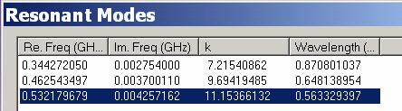
19 Plane Impedance vs. Frequency Structure! 50mm x 50mm! 0.8mm FR4 substrate! Two metal planes Simulation! Compute first twelve resonant modes! Compute S, Y, Z Parameters! Correlate Z11 with resonances Port 1 Port 2

!")
20 Plane Impedance vs. Frequency ! First twelve resonant modes listed! Degenerate modes are grouped (these exist due to square planes)! Seven distinct frequencies are labeled and correlated with Z11 in the plot
21 Design Automation with TPA 4.0! New GUI with native Windows and UNIX versions! Interface to APD, Encore, Zuken CR5000! Lumped Extraction using Multipole technology from Q3D! Distributed Models using Multipole Accelerated PEEC! Automatic Partitioning for full package analysis! Support for all BGA style packages (i.e. CSP, Flip-Chip)


22 Design Automation with TPA 4.0! Easily select critical nets for analysis! Quickly define size and shape of supply planes to be included in analysis! Extract the parasitics for the entire package using Auto-Partitioning! Package data provided in matrix form and as Spice subcircuits


23 3D model of 4 Layer BGA Package for Broadband Simulation Net in green is connected to p-substrate contact. Net in gray is power trace. Net in red is differential trace. Net in deep blue is ground trace. To to make a good noise return path! Vss2 plane Assumed Chip_GND VDD2 plane Package s Vdd1 plane PCB_GND VDD3 plane Package s Vss1 plane Vss2 plane

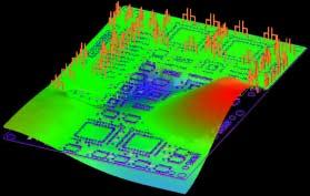
24 Current Distribution with Single-ended 10GHz (single tone)
25 Rough Calculation of Signal Bandwidth For PRBS (Psuedo Random Bit Sequence) signal with the rate of 10Gbps, what will the signal bandwidth will be?? Amp db T 1 T b = 0. 1ns = Rule of Thumb for Signal Bandwidth = rise time T 0.35 b Let' s assume, T = Signal BW = = time 10 Tb 10 rise 35 10GHz 20GHz 30GHz 0.35 t rise time GHz Package is a kind of Low Pass Filter and signal distortion may come from large group delay near the high ripple frequency range of LPF. Therefore, designer need broadband accurate result to predict waveform distortion. Frequency selective channel due to package!!! Signal spectrum! freq 10GHz 20GHz 30GHz
 (I.L. of TxD-)")
26 Broadband Accurate S 31, S 42 for 4 Layer BGA (I.L. of TxD+) (I.L. of TxD-)

27 Broadband Accurate S 21, S 41 for 4 Layer BGA

28 Broadband Accurate S 11, S 22, S 33, S 44 for 4 Layer BGA

29 Broadband Accurate S 77, S 88, S 78 for 4 Layer BGA

30 Broadband Accurate S 55, S 66 for 4 Layer BGA

31 Bit Error Rate (BER) Testing for a Low Voltage Differential Signal (LVDS) with 4 layer BGA package as a Communication Channel Single-ended Waveform Testing in Symphony


32 Symphony s Waveform Check against Full-Wave SPICE Waveform Full Wave SPICE

33 BER Testing Setup in Symphony Data for DC Offset Calibration DC Offset Calibration Creation for LVDS Clock Recovery Section With Early/Late Gate Implementation


34 Post Channel Waveform for High SNR 10 Gbps DC Calibration Eye open ~360mv 20 Gbps Eye open ~275mv

35 BER Testing Result in Symphony 20Gbps 10Gbps
.")

36 CORPORATE OVERVIEW ConnectCom MicroSystems Inc. is a Venture Capital backed Internet Chip Company. It designs and manufactures ultralow power, very high-speed analog and mixed-signal integrated circuits (ICs). These ICs enable and support terabit optical switching equipment and networks that form the new backbone infrastructure for the exploding Internet traffic. ConnectCom employs innovative and patented designs techniques that are technology independent; to achieve power savings of up to 70% over traditional solutions for standards compliant SONET and SDH based applications. This will allow the company to offer superior, predictable economies, reliability and flexibility to the system designers of switch fabrics, DWDM equipment and optical modules. Flip-Chip BGA Package design courtesy of ConnectCom MicroSystems Inc.

37 BGA: Design Example AnsoftLinks IGES, STEP, GDSII, ACIS, DXF, AutoCAD APD Allegro Encore Zuken 3D Physical Model

.! 3D Solid Model is extracted from APD using AnsoftLinks.")
 Critical Nets Power Net Ground Net Victim Net")
38 BGA: Design Example How do we figure out what matters?! Dissect a pair of critical nets and a victim net! Initial design Gb/s Flip-Chip BGA, that was routed using Cadence Advanced Package Designer(APD).! 3D Solid Model is extracted from APD using AnsoftLinks.! Goal: Use Strategic Simulation for improving package performance at higher data rates (25 GHz Bandwidth) Critical Nets Power Net Ground Net Victim Net Return Path Power Signal Net Ground Net Via Solder Balls
39 BGA: Design Example! For initial analysis, create an equivalent circuit model using Ansoft Serenade, assuming:! Nets are on the top layer(trace layer)! Infinite ground/dielectrics and zero thickness traces! The via pads and solder mask are ignored! Approximate trace dimensions and spacing! Demonstrate correlation between tools and show the benefit of first-order design iterations HFSS Model A B C t-line models Ensemble Model Multi-Coupled Line Models (MCPL)
40 BGA: Design Example! Serenade is acceptable comparing with 3D HFSS model S11! Variations in the cross-talk can be attributed to the assumption of uniform spacing, used in the Serenade model, for Section B(See previous slide). Serenade Model! The approximate dimensions used in the Serenade model can be shown to account for the frequency shift. S11! By replacing the transmission line models in Section A with multicoupled lines, the accuracy of the Serenade model can be improved to capture the resonance frequencies that occur above 30GHz. Since this is above the frequency band of interest, we will continue to use the current model. HFSS Model
41 BGA: Design Example! The size of the return path does not appear to have a major impact on the performance. S11! This is further validation that the infinite ground assumption used for the Serenade and Ensemble models is valid.! If we look closer, the finite return path does appear to influence the crosstalk. We will need to investigate and develop guidelines for trace placement relative to the edge of the return path. HFSS Model (Large Return Path ) S11 HFSS Model (Finite Return Path )
42 BGA: Design Example! We see good correlation between Ensemble and HFSS.! In the Ensemble model we used probe ports and assume an infinite ground plane.! Unlike Ensemble, HFSS does not explicitly define ground planes. This will be important as we proceed with the BGA analysis. S11 S11 Ensemble Model (Infinite Ground )! Since Ensemble is only solving for the currents on the conductors, it is considerably faster than HFSS for this problem. HFSS Model (Large Return Path )
 is causing some problems.")

43 BGA: Design Example Viewing the Complex Magnitude of the E-Field in HFSS or Magnitude of J in Ensemble reveals that the guard trace(ground Net) is causing some problems. Ansoft HFSS Ground Net Guard trace is ~λ/2 ~ at 24GHz Ground Net Ansoft Ensemble The Fast Frequency Sweep capabilities in Ansoft HFSS computes S- Parameters and field solutions, swept over frequency, in a single simulation. This allows the engineer to quickly identify, using the Fields Post Processor, any anomalies in the S-Parameters without re-solving.
44 BGA: Design Example It is interesting to note, that if the multi-coupled line models are replaced with a simple microstrip model, the resonance problem that was caused by the guard trace would not have been identified using a circuit tool.! There is no substitute for accurate broad-band models in a circuit simulator! microstrip MCPL
45 BGA: Design Example Since we are getting good agreement between the circuit and field simulator, lets continue to investigate several iterations of the design using only the circuit tool.! First, lets remove the guard trace.! We fixed the resonance, but the system does not appear to be 50Ω S11

46 BGA: Design Example There are several possibilities that could account for the impedance of the transmission lines! We made assumptions about the trace thickness, took liberties with the stack-up, and failed to make adjustments to the trace width.! The Ansoft Serenade Transmission Line Designer reveals that the line impedance is ~100Ω Renormalized to 100 Ω
47 BGA: Design Example! To investigate the stack-up, trace thickness, trace spacing, and trace to edge spacing, we will utilize Spicelink 2D

 Crosstalk")
48 BGA: Design Example Characteristic Impedance vs. Trace Width W d Backward(Near-End) Crosstalk vs. Trace Separation
49 BGA: Design Example Impedance vs. Trace to Ground Edge Spacing l

50 BGA: Design Example! Based on the design rules we generated using Ansoft Spicelink 2D lets pick some guidelines for improving the layout we currently have.! Design Rule: maintain 0.2mm Trace to Ground! Expectation: less then a 0.5Ω impedance variation compared to a trace centered on the return path.! As the rise-times increase, re-routing non-critical nets will become essential to the performance of the the critical nets. The victim net (a non-critical net) may have to be moved. Trace to Edge keep out
51 BGA: Design Example! Design Rule: maintain 0.5mm trace to trace! Note: It is impossible to maintain this spacing with the pin-to-pin spacing at the Die. Removing the victim net could become necessary if the the coupling is determined to be unacceptable.! Before we physically change the routing, lets update our Ansoft Serenade model and quickly verify the design guidelines we have chosen. Trace to Trace Separation
52 BGA: Design Example Renormalized to 100 Ω No Via Pads S11! The Ansoft Serenade model was modified to simulate our new layout design rules.! In addition, the via pads were added to the model. It is obvious from the simulation that something will have to be done to improve the match between the via pad and the transmission lines. Investigation of the via in more detail is recommended.! Ansoft Ensemble was used to verify the circuit model. S11 S11 Renormalized to 100 Ω Via Pads Renormalized to 100 Ω Ansoft Ensemble
53 Summary! Feature Sizes are Decreasing! Clock Frequencies/Edge Rates are Increasing! Digital Design is faced with RF issues! Wide Range of Packaging Choices! Good Design Rules can be Generated with the Appropriate Simulation Tools! Simulation tools can be used to dissect Packages to understand the signal path! Full Packages can be simulated for verification! Successful designs with reduced costs and design cycle time are possible with IC and Package Designers working together through Simulation
54 References [1] David C. Wittwer, William P. Pinello, Intel Corporation, Investigation of Power and Ground Plane Resonance, National Radio Science Meeting, Boulder, CO, Jan. 8-11, 2001
Signal Integrity Modeling and Simulation for IC/Package Co-Design
 Signal Integrity Modeling and Simulation for IC/Package Co-Design Ching-Chao Huang Optimal Corp. October 24, 2004 Why IC and package co-design? The same IC in different packages may not work Package is
EMI. Chris Herrick. Applications Engineer
 Fundamentals of EMI Chris Herrick Ansoft Applications Engineer Three Basic Elements of EMC Conduction Coupling process EMI source Emission Space & Field Conductive Capacitive Inductive Radiative Low, Middle
Evaluation of Package Properties for RF BJTs
 Application Note Evaluation of Package Properties for RF BJTs Overview EDA simulation software streamlines the development of digital and analog circuits from definition of concept and estimation of required
How to anticipate Signal Integrity Issues: Improve my Channel Simulation by using Electromagnetic based model
 How to anticipate Signal Integrity Issues: Improve my Channel Simulation by using Electromagnetic based model HSD Strategic Intent Provide the industry s premier HSD EDA software. Integration of premier
Relationship Between Signal Integrity and EMC
 Relationship Between Signal Integrity and EMC Presented by Hasnain Syed Solectron USA, Inc. RTP, North Carolina Email: HasnainSyed@solectron.com 06/05/2007 Hasnain Syed 1 What is Signal Integrity (SI)?
ANSYS CPS SOLUTION FOR SIGNAL AND POWER INTEGRITY
 ANSYS CPS SOLUTION FOR SIGNAL AND POWER INTEGRITY Rémy FERNANDES Lead Application Engineer ANSYS 1 2018 ANSYS, Inc. February 2, 2018 ANSYS ANSYS - Engineering simulation software leader Our industry reach
PDS Impact for DDR Low Cost Design
 PDS Impact for DDR3-1600 Low Cost Design Jack W.C. Lin Sr. AE Manager jackl@cadence.com Aug. g 13 2013 Cadence, OrCAD, Allegro, Sigrity and the Cadence logo are trademarks of Cadence Design Systems, Inc.
Microcircuit Electrical Issues
 Microcircuit Electrical Issues Distortion The frequency at which transmitted power has dropped to 50 percent of the injected power is called the "3 db" point and is used to define the bandwidth of the
Optimization of Wafer Level Test Hardware using Signal Integrity Simulation
 June 7-10, 2009 San Diego, CA Optimization of Wafer Level Test Hardware using Signal Integrity Simulation Jason Mroczkowski Ryan Satrom Agenda Industry Drivers Wafer Scale Test Interface Simulation Simulation
A Simulation Study of Simultaneous Switching Noise
 A Simulation Study of Simultaneous Switching Noise Chi-Te Chen 1, Jin Zhao 2, Qinglun Chen 1 1 Intel Corporation Network Communication Group, LOC4/19, 9750 Goethe Road, Sacramento, CA 95827 Tel: 916-854-1178,
Design Considerations for Highly Integrated 3D SiP for Mobile Applications
 Design Considerations for Highly Integrated 3D SiP for Mobile Applications FDIP, CA October 26, 2008 Joungho Kim at KAIST joungho@ee.kaist.ac.kr http://tera.kaist.ac.kr Contents I. Market and future direction
Figure 1. Inductance
 Tools for On-Chip Interconnect Inductance Extraction Jerry Tallinger OEA International Inc. 155 East Main Ave., Ste. 110 Morgan Hill, CA 95037 jerry@oea.com Haris Basit OEA International Inc. 155 East
EMI Reduction on an Automotive Microcontroller
 EMI Reduction on an Automotive Microcontroller Design Automation Conference, July 26 th -31 st, 2009 Patrice JOUBERT DORIOL 1, Yamarita VILLAVICENCIO 2, Cristiano FORZAN 1, Mario ROTIGNI 1, Giovanni GRAZIOSI
Signal Integrity Design of TSV-Based 3D IC
 Signal Integrity Design of TSV-Based 3D IC October 24, 21 Joungho Kim at KAIST joungho@ee.kaist.ac.kr http://tera.kaist.ac.kr 1 Contents 1) Driving Forces of TSV based 3D IC 2) Signal Integrity Issues
Taking the Mystery out of Signal Integrity
 Slide - 1 Jan 2002 Taking the Mystery out of Signal Integrity Dr. Eric Bogatin, CTO, GigaTest Labs Signal Integrity Engineering and Training 134 S. Wolfe Rd Sunnyvale, CA 94086 408-524-2700 www.gigatest.com
EMC cases study. Antonio Ciccomancini Scogna, CST of America CST COMPUTER SIMULATION TECHNOLOGY
 EMC cases study Antonio Ciccomancini Scogna, CST of America antonio.ciccomancini@cst.com Introduction Legal Compliance with EMC Standards without compliance products can not be released to the market Failure
DL-150 The Ten Habits of Highly Successful Designers. or Design for Speed: A Designer s Survival Guide to Signal Integrity
 Slide -1 Ten Habits of Highly Successful Board Designers or Design for Speed: A Designer s Survival Guide to Signal Integrity with Dr. Eric Bogatin, Signal Integrity Evangelist, Bogatin Enterprises, www.bethesignal.com
3D IC-Package-Board Co-analysis using 3D EM Simulation for Mobile Applications
 3D IC-Package-Board Co-analysis using 3D EM Simulation for Mobile Applications Darryl Kostka, CST of America Taigon Song and Sung Kyu Lim, Georgia Institute of Technology Outline Introduction TSV Array
A passive circuit based RF optimization methodology for wireless sensor network nodes. Article (peer-reviewed)
") Title Author(s) Editor(s) A passive circuit based RF optimization methodology for wireless sensor network nodes Zheng, Liqiang; Mathewson, Alan; O'Flynn, Brendan; Hayes, Michael; Ó Mathúna, S. Cian Wu,
Title Author(s) Editor(s) A passive circuit based RF optimization methodology for wireless sensor network nodes Zheng, Liqiang; Mathewson, Alan; O'Flynn, Brendan; Hayes, Michael; Ó Mathúna, S. Cian Wu,
Source: Nanju Na Jean Audet David R Stauffer IBM Systems and Technology Group
 Title: Package Model Proposal Source: Nanju Na (nananju@us.ibm.com) Jean Audet (jaudet@ca.ibm.com), David R Stauffer (dstauffe@us.ibm.com) Date: Dec 27 IBM Systems and Technology Group Abstract: New package
Reliable World Class Insights Your Silicon Valley Partner in Simulation ANSYS Sales, Consulting, Training & Support
 www.ozeninc.com info@ozeninc.com (408) 732 4665 1210 E Arques Ave St 207 Sunnyvale, CA 94085 Reliable World Class Insights Your Silicon Valley Partner in Simulation ANSYS Sales, Consulting, Training &
EMI/EMC of Entire Automotive Vehicles and Critical PCB s. Makoto Suzuki Ansoft Corporation
 EMI/EMC of Entire Automotive Vehicles and Critical PCB s Makoto Suzuki Ansoft Corporation WT10_SI EMI/EMC of Entire Automotive Vehicles and Critical PCB s Akira Ohta, Toru Watanabe, Benson Wei Makoto Suzuki
DL-150 The Ten Habits of Highly Successful Designers. or Design for Speed: A Designer s Survival Guide to Signal Integrity
 Slide -1 Ten Habits of Highly Successful Board Designers or Design for Speed: A Designer s Survival Guide to Signal Integrity with Dr. Eric Bogatin, Signal Integrity Evangelist, Bogatin Enterprises, www.bethesignal.com
PCB Routing Guidelines for Signal Integrity and Power Integrity
 PCB Routing Guidelines for Signal Integrity and Power Integrity Presentation by Chris Heard Orange County chapter meeting November 18, 2015 1 Agenda Insertion Loss 101 PCB Design Guidelines For SI Simulation
Design of the Power Delivery System for Next Generation Gigahertz Packages
 Design of the Power Delivery System for Next Generation Gigahertz Packages Madhavan Swaminathan Professor School of Electrical and Computer Engg. Packaging Research Center madhavan.swaminathan@ece.gatech.edu
Optimizing Design of a Probe Card using a Field Solver
 Optimizing Design of a Probe Card using a Field Solver Rey Rincon, r-rincon@ti.com Texas Instruments 13020 Floyd Rd MS 3616 Dallas, TX. 75243 972-917-4303 Eric Bogatin, bogatin@ansoft.com Bill Beale, beale@ansoft.com
High Speed Digital Systems Require Advanced Probing Techniques for Logic Analyzer Debug
 JEDEX 2003 Memory Futures (Track 2) High Speed Digital Systems Require Advanced Probing Techniques for Logic Analyzer Debug Brock J. LaMeres Agilent Technologies Abstract Digital systems are turning out
MSPP Page 1. MSPP Competencies in SiP Integration for Wireless Applications
 MSPP Page 1 MSPP Competencies in SiP Integration for Wireless Applications MSPP Page 2 Outline Design, simulation and measurements tools MSPP competencies in electrical design and modeling Embedded passive
When Should You Apply 3D Planar EM Simulation?
 When Should You Apply 3D Planar EM Simulation? Agilent EEsof EDA IMS 2010 MicroApps Andy Howard Agilent Technologies 1 3D planar EM is now much more of a design tool Solves bigger problems and runs faster
DesignCon Design of Gb/s Interconnect for High-bandwidth FPGAs. Sherri Azgomi, Altera Corporation
 DesignCon 2004 Design of 3.125 Gb/s Interconnect for High-bandwidth FPGAs Sherri Azgomi, Altera Corporation sazgomi@altera.com Lawrence Williams, Ph.D., Ansoft Corporation williams@ansoft.com CF-031505-1.0
Compensation for Simultaneous Switching Noise in VLSI Packaging Brock J. LaMeres University of Colorado September 15, 2005
 Compensation for Simultaneous Switching Noise in VLSI Packaging Brock J. LaMeres University of Colorado 1 Problem Statement Package Interconnect Limits VLSI System Performance The three main components
Design and Matching of a 60-GHz Printed Antenna
 Application Example Design and Matching of a 60-GHz Printed Antenna Using NI AWR Software and AWR Connected for Optenni Figure 1: Patch antenna performance. Impedance matching of high-frequency components
Ansoft Electronic Design Automation
 Ansoft Electronic Design Automation Desmond Tan Technical Manager ANSOFT, LLC. 28 Ansoft, LLC All rights reserved. Ansoft, LLC Proprietary Ansoft Products And Technology Ansoft provides state-of-the-art
Aries Kapton CSP socket
 Aries Kapton CSP socket Measurement and Model Results prepared by Gert Hohenwarter 5/19/04 1 Table of Contents Table of Contents... 2 OBJECTIVE... 3 METHODOLOGY... 3 Test procedures... 4 Setup... 4 MEASUREMENTS...
Engineering the Power Delivery Network
 C HAPTER 1 Engineering the Power Delivery Network 1.1 What Is the Power Delivery Network (PDN) and Why Should I Care? The power delivery network consists of all the interconnects in the power supply path
Signal integrity means clean
 CHIPS & CIRCUITS As you move into the deep sub-micron realm, you need new tools and techniques that will detect and remedy signal interference. Dr. Lynne Green, HyperLynx Division, Pads Software Inc The
Ansys Designer RF Training Lecture 3: Nexxim Circuit Analysis for RF
 Ansys Designer RF Solutions for RF/Microwave Component and System Design 7. 0 Release Ansys Designer RF Training Lecture 3: Nexxim Circuit Analysis for RF Designer Overview Ansoft Designer Advanced Design
Si-Interposer Collaboration in IC/PKG/SI. Eric Chen
 Si-Interposer Collaboration in IC/PKG/SI Eric Chen 4/Jul/2014 Design Overview U-bump Logic IC Mem IC C4 bump Logic IC Silicon/Organic substrate Interposer Mem IC CAP Package substrate Solder Ball VRM BGA
Electrical Characterization of a 64 Ball Grid Array Package
 EMC Europe - Hamburg, 8 th September 008 Summary Electrical Characterization of a 64 Ball Grid Array A. Boyer (), E. Sicard (), M. Fer (), L. Courau () () LATTIS - INSA of Toulouse - France () ST-Microelectronics
The Design Challenge to Integrate High Performance Organic Packaging into High End ASIC Strategic Space Based Applications.
 The Design Challenge to Integrate High Performance Organic Packaging into High End ASIC Strategic Space Based Applications May 8, 2007 Abstract: The challenge to integrate high-end, build-up organic packaging
Adding On-Chip Capacitance in IBIS Format for SSO Simulation
 Adding On-Chip Capacitance in IBIS Format for SSO Simulation Raymond Y. Chen SIGRITY, Inc. Jan. 2004 DesignCon 2004 - IBIS Summit Presentation Agenda 1. Is IBIS good for SSO simulation 2. SSO simulation
MMIC/RFIC Packaging Challenges Webcast (July 28, AM PST 12PM EST)
") MMIC/RFIC Packaging Challenges Webcast ( 9AM PST 12PM EST) Board Package Chip HEESOO LEE Agilent EEsof 3DEM Technical Lead 1 Agenda 1. MMIC/RFIC packaging challenges 2. Design techniques and solutions
MMIC/RFIC Packaging Challenges Webcast ( 9AM PST 12PM EST) Board Package Chip HEESOO LEE Agilent EEsof 3DEM Technical Lead 1 Agenda 1. MMIC/RFIC packaging challenges 2. Design techniques and solutions
Aries CSP microstrip socket Cycling test
 Aries CSP microstrip socket Cycling test RF Measurement Results prepared by Gert Hohenwarter 2/18/05 1 Table of Contents TABLE OF CONTENTS... 2 OBJECTIVE... 3 METHODOLOGY... 3 Test procedures... 6 Setup...
Preliminary Product Overview
 Preliminary Product Overview Features DC to > 3 GHz Frequency Range 25 Watt (CW), 200W (Pulsed) Max Power Handling Low On-State Insertion Loss, typical 0.3 db @ 3 GHz Low On-State Resistance < 0.75 Ω 25dB
Chip Package - PC Board Co-Design: Applying a Chip Power Model in System Power Integrity Analysis
 Chip Package - PC Board Co-Design: Applying a Chip Power Model in System Power Integrity Analysis Authors: Rick Brooks, Cisco, ricbrook@cisco.com Jane Lim, Cisco, honglim@cisco.com Udupi Harisharan, Cisco,
Case Study Package Design & SI/PI analysis
 Caliber Interconnect Solutions Design for perfection Case Study Package Design & SI/PI analysis Caliber Interconnect Solutions (Pvt) Ltd No 6,1 st Street Gandhi Nagar, Kavundampalayam, Coimbatore-30. Tamil
Application Note 5525
 Using the Wafer Scale Packaged Detector in 2 to 6 GHz Applications Application Note 5525 Introduction The is a broadband directional coupler with integrated temperature compensated detector designed for
Introduction to Electromagnetic Compatibility
 Introduction to Electromagnetic Compatibility Second Edition CLAYTON R. PAUL Department of Electrical and Computer Engineering, School of Engineering, Mercer University, Macon, Georgia and Emeritus Professor
On Chip Active Decoupling Capacitors for Supply Noise Reduction for Power Gating and Dynamic Dual Vdd Circuits in Digital VLSI
 ELEN 689 606 Techniques for Layout Synthesis and Simulation in EDA Project Report On Chip Active Decoupling Capacitors for Supply Noise Reduction for Power Gating and Dynamic Dual Vdd Circuits in Digital
Development and Validation of a Microcontroller Model for EMC
 Development and Validation of a Microcontroller Model for EMC Shaohua Li (1), Hemant Bishnoi (1), Jason Whiles (2), Pius Ng (3), Haixiao Weng (2), David Pommerenke (1), and Daryl Beetner (1) (1) EMC lab,
BASIS OF ELECTROMAGNETIC COMPATIBILITY OF INTEGRATED CIRCUIT Chapter VI - MODELLING PCB INTERCONNECTS Corrections of exercises
 BASIS OF ELECTROMAGNETIC COMPATIBILITY OF INTEGRATED CIRCUIT Chapter VI - MODELLING PCB INTERCONNECTS Corrections of exercises I. EXERCISE NO 1 - Spot the PCB design errors Spot the six design errors in
Validation Report Comparison of Eye Patterns Generated By Synopsys HSPICE and the Agilent PLTS
 Comparison of Eye Patterns Generated By Synopsys HSPICE and the Agilent PLTS Using: Final Inch Test/Eval Kit, Differential Pair - No Grounds Configuration, QTE-DP/QSE-DP, 5mm Stack Height (P/N FIK-QxE-04-01)
A DESIGN EXPERIMENT FOR MEASUREMENT OF THE SPECTRAL CONTENT OF SUBSTRATE NOISE IN MIXED-SIGNAL INTEGRATED CIRCUITS
 A DESIGN EXPERIMENT FOR MEASUREMENT OF THE SPECTRAL CONTENT OF SUBSTRATE NOISE IN MIXED-SIGNAL INTEGRATED CIRCUITS Marc van Heijningen, John Compiet, Piet Wambacq, Stéphane Donnay and Ivo Bolsens IMEC
Demystifying Vias in High-Speed PCB Design
 Demystifying Vias in High-Speed PCB Design Keysight HSD Seminar Mastering SI & PI Design db(s21) E H What is Via? Vertical Interconnect Access (VIA) An electrical connection between layers to pass a signal
VLSI is scaling faster than number of interface pins
 High Speed Digital Signals Why Study High Speed Digital Signals Speeds of processors and signaling Doubled with last few years Already at 1-3 GHz microprocessors Early stages of terahertz Higher speeds
544 IEEE TRANSACTIONS ON ADVANCED PACKAGING, VOL. 31, NO. 3, AUGUST /$ IEEE
 544 IEEE TRANSACTIONS ON ADVANCED PACKAGING, VOL. 31, NO. 3, AUGUST 2008 Modeling and Measurement of Interlevel Electromagnetic Coupling and Fringing Effect in a Hierarchical Power Distribution Network
Broadband Methodology for Power Distribution System Analysis of Chip, Package and Board for High Speed IO Design
 DesignCon 2009 Broadband Methodology for Power Distribution System Analysis of Chip, Package and Board for High Speed IO Design Hsing-Chou Hsu, VIA Technologies jimmyhsu@via.com.tw Jack Lin, Sigrity Inc.
Logic Analyzer Probing Techniques for High-Speed Digital Systems
 DesignCon 2003 High-Performance System Design Conference Logic Analyzer Probing Techniques for High-Speed Digital Systems Brock J. LaMeres Agilent Technologies Abstract Digital systems are turning out
Advanced Transmission Lines. Transmission Line 1
 Advanced Transmission Lines Transmission Line 1 Transmission Line 2 1. Transmission Line Theory :series resistance per unit length in. :series inductance per unit length in. :shunt conductance per unit
Flip-Chip for MM-Wave and Broadband Packaging
 1 Flip-Chip for MM-Wave and Broadband Packaging Wolfgang Heinrich Ferdinand-Braun-Institut für Höchstfrequenztechnik (FBH) Berlin / Germany with contributions by F. J. Schmückle Motivation Growing markets
Innovations in EDA Webcast Series
 Welcome Innovations in EDA Webcast Series August 2, 2012 Jack Sifri MMIC Design Flow Specialist IC, Laminate, Package Multi-Technology PA Module Design Methodology Realizing the Multi-Technology Vision
CROSSTALK DUE TO PERIODIC PLANE CUTOUTS. Jason R. Miller, Gustavo Blando, Istvan Novak Sun Microsystems
 CROSSTALK DUE TO PERIODIC PLANE CUTOUTS Jason R. Miller, Gustavo Blando, Istvan Novak Sun Microsystems 1 Outline 1 Introduction 2 Crosstalk Theory 3 Measurement 4 Simulation correlation 5 Parameterized
Modeling and Simulation of Powertrains for Electric and Hybrid Vehicles
 Modeling and Simulation of Powertrains for Electric and Hybrid Vehicles Dr. Marco KLINGLER PSA Peugeot Citroën Vélizy-Villacoublay, FRANCE marco.klingler@mpsa.com FR-AM-5 Background The automotive context
Signal/Power Integrity Analysis of High-Speed Memory Module with Meshed Reference Plane 1
 , pp.119-128 http//dx.doi.org/10.14257/ijca.2018.11.7.10 Signal/Power Integrity Analysis of High-Speed Memory Module with Meshed Reference Plane 1 Moonjung Kim Institute of IT Convergence Technology, Dept.
Impact of On-Chip Multi-Layered Inductor on Signal and Power Integrity of Underlying Power-Ground Net
 22 nd IEEE Workshop on Signal and Power Integrity, Brest, FRANCE May 25, 2018 Impact of On-Chip Multi-Layered Inductor on Signal and Power Integrity of Underlying Power-Ground Net Akira Tsuchicya 1, Akitaka
A Simulation Methodology for Wirebonds Interconnects of Radiofrequency Integrated Circuits
 A Simulation Methodology for Wirebonds Interconnects of Radiofrequency Integrated Circuits Hercílio M. Cavalcanti 1 and Leandro T. Manera 2 1 Hercílio M. Cavalcanti, CTI Renato Archer, Campinas, São Paulo,
3 GHz Wide Frequency Model of Surface Mount Technology (SMT) Ferrite Bead for Power/Ground and I/O Line Noise Simulation of High-speed PCB
 Ferrite Bead for Power/Ground and I/O Line Noise Simulation of High-speed PCB") 3 GHz Wide Frequency Model of Surface Mount Technology (SMT) Ferrite Bead for Power/Ground and I/O Line Noise Simulation of High-speed PCB Tae Hong Kim, Hyungsoo Kim, Jun So Pak, and Joungho Kim Terahertz
3 GHz Wide Frequency Model of Surface Mount Technology (SMT) Ferrite Bead for Power/Ground and I/O Line Noise Simulation of High-speed PCB Tae Hong Kim, Hyungsoo Kim, Jun So Pak, and Joungho Kim Terahertz
Electromagnetic Simulation of Antennas Installed Inside Vehicles An Automotive EMC Approach Markus Kopp Product Manager, Electronics
 Electromagnetic Simulation of Antennas Installed Inside Vehicles An Automotive EMC Approach Markus Kopp Product Manager, Electronics 1 Automotive Antenna Systems and Automotive EMC Recent technology implementations
DATASHEET CADENCE QRC EXTRACTION
 DATASHEET Cadence QRC Etraction, the industry s premier 3D fullchip parasitic etractor that is independent of design style or flow, is a fast and accurate RLCK etraction solution used during design implementation
Design Guide for High-Speed Controlled Impedance Circuit Boards
 IPC-2141A ASSOCIATION CONNECTING ELECTRONICS INDUSTRIES Design Guide for High-Speed Controlled Impedance Circuit Boards Developed by the IPC Controlled Impedance Task Group (D-21c) of the High Speed/High
Low Noise Amplifier Design Methodology Summary By Ambarish Roy, Skyworks Solutions, Inc.
 February 2014 Low Noise Amplifier Design Methodology Summary By Ambarish Roy, Skyworks Solutions, Inc. Low Noise Amplifiers (LNAs) amplify weak signals received by the antenna in communication systems.
Using Sonnet EM Analysis with Cadence Virtuoso in RFIC Design. Sonnet Application Note: SAN-201B July 2011
 Using Sonnet EM Analysis with Cadence Virtuoso in RFIC Design Sonnet Application Note: SAN-201B July 2011 Description of Sonnet Suites Professional Sonnet Suites Professional is an industry leading full-wave
Best Design and Layout Practices for SiTime Oscillators
 March 17, 2016 Best Design and Layout Practices 1 Introduction... 1 2 Decoupling... 1 3 Bypassing... 4 4 Power Supply Noise Reduction... 5 5 Power Supply Management... 6 6 Layout Recommendations for SiTime
Hot Topics and Cool Ideas in Scaled CMOS Analog Design
 Engineering Insights 2006 Hot Topics and Cool Ideas in Scaled CMOS Analog Design C. Patrick Yue ECE, UCSB October 27, 2006 Slide 1 Our Research Focus High-speed analog and RF circuits Device modeling,
MPC 5534 Case study. E. Sicard (1), B. Vrignon (2) Toulouse France. Contact : web site :
, B. Vrignon (2) Toulouse France. Contact : web site :") MPC 5534 Case study E. Sicard (1), B. Vrignon (2) (1) INSA-GEI, 135 Av de Rangueil 31077 Toulouse France (2) Freescale Semiconductors, Toulouse, France Contact : etienne.sicard@insa-toulouse.fr web site
MPC 5534 Case study E. Sicard (1), B. Vrignon (2) (1) INSA-GEI, 135 Av de Rangueil 31077 Toulouse France (2) Freescale Semiconductors, Toulouse, France Contact : etienne.sicard@insa-toulouse.fr web site
Chapter 16 PCB Layout and Stackup
 Chapter 16 PCB Layout and Stackup Electromagnetic Compatibility Engineering by Henry W. Ott Foreword The PCB represents the physical implementation of the schematic. The proper design and layout of a printed
DesignCon 2003 High-Performance System Design Conference (HP3-5)
") DesignCon 2003 High-Performance System Design Conference (HP3-5) Logic Analyzer Probing Techniques for High-Speed Digital Systems Author/Presenter: Brock LaMeres Hardware Design Engineer Logic Analyzer
DesignCon 2003 High-Performance System Design Conference (HP3-5) Logic Analyzer Probing Techniques for High-Speed Digital Systems Author/Presenter: Brock LaMeres Hardware Design Engineer Logic Analyzer
Challenges and Solutions for Removing Fixture Effects in Multi-port Measurements
 DesignCon 2008 Challenges and Solutions for Removing Fixture Effects in Multi-port Measurements Robert Schaefer, Agilent Technologies schaefer-public@agilent.com Abstract As data rates continue to rise
SUBSTRATE NOISE FULL-CHIP LEVEL ANALYSIS FLOW FROM EARLY DESIGN STAGES TILL TAPEOUT. Hagay Guterman, CSR Jerome Toublanc, Ansys
 SUBSTRATE NOISE FULL-CHIP LEVEL ANALYSIS FLOW FROM EARLY DESIGN STAGES TILL TAPEOUT Hagay Guterman, CSR Jerome Toublanc, Ansys Speakers Hagay Guterman, CSR Hagay Guterman is a senior signal and power integrity
March 4-7, 2018 Hilton Phoenix / Mesa Hotel Mesa, Arizona Archive
 March 4-7, 2018 Hilton Phoenix / Mesa Hotel Mesa, Arizona Archive 2018 BiTS Workshop Image: pilgrims49 / istock COPYRIGHT NOTICE The presentation(s)/poster(s) in this publication comprise the Proceedings
High Frequency Structure Simulator (HFSS) Tutorial
 Tutorial") High Frequency Structure Simulator (HFSS) Tutorial Prepared by Dr. Otman El Mrabet IETR, UMR CNRS 6164, INSA, 20 avenue Butte des Coësmes 35043 Rennes, FRANCE 2005-2006 TABLE OF CONTENTS INTRODUCTION...
High Frequency Structure Simulator (HFSS) Tutorial Prepared by Dr. Otman El Mrabet IETR, UMR CNRS 6164, INSA, 20 avenue Butte des Coësmes 35043 Rennes, FRANCE 2005-2006 TABLE OF CONTENTS INTRODUCTION...
Electromagnetic Analysis of AC Coupling Capacitor Mounting Structures
 Simbeor Application Note #2008_02, April 2008 2008 Simberian Inc. Electromagnetic Analysis of AC Coupling Capacitor Mounting Structures Simberian, Inc. www.simberian.com Simbeor : Easy-to-Use, Efficient
Simulation and Design of Printed Circuit Boards Utilizing Novel Embedded Capacitance Material
 Simulation and Design of Printed Circuit Boards Utilizing Novel Embedded Capacitance Material April 28, 2010 Yu Xuequan, Yanhang, Zhang Gezi, Wang Haisan Huawei Technologies CO., LTD. Shanghai, China Tony_yu@huawei.com
A Miniaturized Wide-Band LTCC Based Fractal Antenna
 A Miniaturized Wide-Band LTCC Based Fractal Antenna Farhan A. Ghaffar, Atif Shamim and Khaled N. Salama Electrical Engineering Program King Abdullah University of Science and Technology Thuwal 23955-6500,
RF Board Design for Next Generation Wireless Systems
 RF Board Design for Next Generation Wireless Systems Page 1 Introduction Purpose: Provide basic background on emerging WiMax standard Introduce a new tool for Genesys that will aide in the design and verification
Nonlinear Full Wave Time Domain Solutions using FDTD_SPICE for High Speed Digital and RF
 Nonlinear Full Wave Time Domain Solutions using FDTD_SPICE for High Speed Digital and RF Neven Orhanovic Raj Raghuram Norio Matsui 1641 North First Street, Ste 170 San Jose, CA-95112 PH: 408-436-9070 FAX:
DesignCon Effect of Power Plane Inductance on Power Delivery Networks. Shirin Farrahi, Cadence Design Systems
 DesignCon 2019 Effect of Power Plane Inductance on Power Delivery Networks Shirin Farrahi, Cadence Design Systems shirinf@cadence.com, 978-262-6008 Ethan Koether, Oracle Corp ethan.koether@oracle.com Mehdi
ECE 497 JS Lecture - 22 Timing & Signaling
 ECE 497 JS Lecture - 22 Timing & Signaling Spring 2004 Jose E. Schutt-Aine Electrical & Computer Engineering University of Illinois jose@emlab.uiuc.edu 1 Announcements - Signaling Techniques (4/27) - Signaling
Full Wave Solution for Intel CPU With a Heat Sink for EMC Investigations
 Full Wave Solution for Intel CPU With a Heat Sink for EMC Investigations Author Lu, Junwei, Zhu, Boyuan, Thiel, David Published 2010 Journal Title I E E E Transactions on Magnetics DOI https://doi.org/10.1109/tmag.2010.2044483
Practical Limitations of State of the Art Passive Printed Circuit Board Power Delivery Networks for High Performance Compute Systems
 Practical Limitations of State of the Art Passive Printed Circuit Board Power Delivery Networks for High Performance Compute Systems Presented by Chad Smutzer Mayo Clinic Special Purpose Processor Development
Digital Systems Power, Speed and Packages II CMPE 650
 Speed VLSI focuses on propagation delay, in contrast to digital systems design which focuses on switching time: A B A B rise time propagation delay Faster switching times introduce problems independent
DesignCon Control of Electromagnetic Radiation from Integrated Circuit Heat sinks. Cristian Tudor, Fidus Systems Inc.
 DesignCon 2009 Control of Electromagnetic Radiation from Integrated Circuit Heat sinks Cristian Tudor, Fidus Systems Inc. Cristian.Tudor@fidus.ca Syed. A. Bokhari, Fidus Systems Inc. Syed.Bokhari@fidus.ca
AN ABSTRACT OF THE THESIS OF
 AN ABSTRACT OF THE THESIS OF Shannon Mark for the degree of Master of Science in Electrical and Computer Engineering presented on June 3, 2011. Title: Dual Referencing Guidelines to Minimize Power Delivery
Aries Center probe CSP socket Cycling test
 Aries Center probe CSP socket Cycling test RF Measurement Results prepared by Gert Hohenwarter 10/27/04 1 Table of Contents TABLE OF CONTENTS... 2 OBJECTIVE... 3 METHODOLOGY... 3 Test procedures... 5 Setup...
The number of layers The number and types of planes (power and/or ground) The ordering or sequence of the layers The spacing between the layers
 The ordering or sequence of the layers The spacing between the layers") PCB Layer Stackup PCB layer stackup (the ordering of the layers and the layer spacing) is an important factor in determining the EMC performance of a product. The following four factors are important with
PCB Layer Stackup PCB layer stackup (the ordering of the layers and the layer spacing) is an important factor in determining the EMC performance of a product. The following four factors are important with
Signal Integrity Tips and Techniques Using TDR, VNA and Modeling. Russ Kramer O.J. Danzy
 Signal Integrity Tips and Techniques Using TDR, VNA and Modeling Russ Kramer O.J. Danzy Simulation What is the Signal Integrity Challenge? Tx Rx Channel Asfiakhan Dreamstime.com - 3d People Communication
Five Emerging Technologies that will Revolutionize High Speed Systems
 lide - 1 Five Emerging Technologies that will Revolutionize High peed ystems Dr. Eric Bogatin, CTO eric@gigatest.com 913-393-1305 GigaTest Labs 134 Wolfe Rd unnyvale, CA 94086 Presented at the High-peed
MICTOR. High-Speed Stacking Connector
 MICTOR High-Speed Stacking Connector Electrical Performance Report for the 0.260" (6.6-mm) Stack Height Connector.......... Connector With Typical Footprint................... Connector in a System Report
ISSCC 2006 / SESSION 10 / mm-wave AND BEYOND / 10.1
 10.1 A 77GHz 4-Element Phased Array Receiver with On-Chip Dipole Antennas in Silicon A. Babakhani, X. Guan, A. Komijani, A. Natarajan, A. Hajimiri California Institute of Technology, Pasadena, CA Achieving
10 COVER FEATURE CAD/EDA FOCUS
 10 COVER FEATURE CAD/EDA FOCUS Effective full 3D EMI analysis of complex PCBs by utilizing the latest advances in numerical methods combined with novel time-domain measurement technologies. By Chung-Huan