important notice This manual contains suggestions and guidelines on how to install the subject Quality Metals
|
|
|
- Augusta Doyle
- 5 years ago
- Views:
Transcription
1 ml-200
2 important notice This manual contains suggestions and guidelines on how to install the subject Quality Metals time without incurring any obligations. To insure you have the latest information available, please inquire or visit our website. Application and design details are for illustrative purposes only and may not be appropriate for all environmental conditions and/or building designs. Projects should be engineered and installed to conform to applicable building codes, regulations, and accepted industry practices.
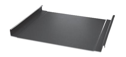
3 Introduction ML-200 is a non-structural panel which is mechanically seamed during installation. The product is an integral interlocking system by design meaning the panels install in one direction from a given starting point. with a wide range of building designs. Two clips are center point allowing for multi-directional expansion. Factory Apply Sealant available. Applications fascia, equipment screens, mansards, and wall panels. This system may also be installed on tapered and curved roof areas. other applications. Design ML-200 Standing Seam requires low maintenance. The panel is secured with concealed clips and the panel side laps are locked together using a rooftop seaming machine. Testing UL 790 Fire Test of Roof Coverings, Class A, B, C UL 2218 For Impact Resistance, Class 4 UL 580 Uplift Resistance. Class 90 Construction No. 90, 176, 180, 238, 238A, 238B, 298, 437, 449, 451, 452, 482, 487, 633, 639 INSTALLATION Solid Substrate Required Snap Seam No Field Seaming Required Weather Tight Warranty is not Available Underlayment Polystick-MTS - Polyglass Oil Canning reduce the incidence of oil canning in the panels. Specifications Color and Finishes 24 and 26 Gauge Galvalume 35 Year Finish Warranty on Kynar 500 Finish Widths Actual Panel Coverage (Width): Minimum Slope = ½":12" Lengths ML-200 Panel is available in standard lengths from 4 to 40. Longer lengths require additional handling, packaging, and shipping considerations. An extra handling charge may apply to panels over 40. Continuous Rollformed Lengths: eliminates need for panel lap joints. Installer must have prior experience and knowledge of the tolls listed below and their uses in working with Caulking Gun Snips Cordless Screw Gun Pop Rivet Tool Tape Measure Hemming Tool Electrical Extension Cord Heavy Gloves Safety Glasses
4 Packaging Options Standard packing A packaging charge will be added to all orders. Standard packing is crating for all orders. Storage Bare Galvalume and painted panels can be expected to give many years of rust-free service when precautions are taken during storage. If metal is not to be used immediately, store inside in a well ventilated, dry location. Any outdoor storage is at the customer s own risk! At time of delivery, inspect panels for moisture. If moisture has formed, the panels should be uncrated, wiped dry, and allowed to dry completely. Failure to remove the entrapped moisture between the sheets immedi- Extended storage of panels in a bundle is not recommended. Storage on Roof, Crates need to be placed parallel to the framing members and the slope of the roof. LTL packing For LTL, panels are packaged in a completely enclose crate to provide optimum protection. Additional charges will apply for non-standard packing and special requests. Strippable film Removal applied to the topside of the panel to prevent possible damage to the painted surface. If panel has a protective sunlight and high temperatures. remain on the panels after installation. Lead Time Please allow 2-3 days for delivery for material or colors we have in stock. Color we have to paint please allow working days. Receiving Materials It is the responsibility of the installer to unload material from the delivery truck. The installer shall be responsible for providing suitable equipment for unloading of material from the delivery truck. After receiving material, check the condition of the material, and review the shipment against the shipping list to ensure all materials are accounted for. If damages or shortages are discovered, it should be noted on the shipping copy at time of delivery. If material is delivered by common carrier, a claim must be made with the carrier as soon as possible
5 mechanical handling: Forklift A forklift may be used for panels up to 20 long. Please make sure the forks are at their maximum separation. Do nor transport open crates. When transporting crates across rough terrain, or for a long distance, some means of supporting the panel load must be used. Improper loading and unloading of crates may result in bodily harm and /or material damage. Union Corrugating is not responsible for bodily injuries and/or material damages resulting from impoper loading and unloading. general handling Each crate should be handled carefully to avoid being damaged. Care should be taken to prevent bending of for proper care while unloading and handling crates in order to prevent panel damage: 1. Crates should remain intact during any handling, and until the individual panels in each bundle are ready to be installed. Crates should never be lifted by the banding. 2. Lift each crate as close as possible to its center of gravity. crane A crane should be used when lifting panels with lengths greater than 20. please be sure to utilize a spreader bar to ensure the even distribution of the weight to the pick up points. As a rule, when lifting panels, no more than 1/3 of the length of the panel should be left unsupported. Canvas or nylon slings should be used to pick up the panels. DO NOT use cable or chains because this will damage the panels. 3. If the crates are to be lifted with a crane, use a spreader bar of appropriate length, and nylon band slings. (Do not use wire rope slings as they will damage the panels). 4. Depending on panel length, some crates may be lifted by a forklift. When using a forklift, the forks should be spread apart to their maximum spacing, and the load must be centered on the forks to prevent scratching the next panel. A panel should never be picked up by it s ends. Instead, lift the panel along its longitudinal panels over 10 feet long, two or more people should lift the panel along the same edge. 5. After creates are opened, individual panels must also be handled carefully to prevent panel buckling or damage to the panel coating. When removing a panel from a crate, it should never be allowed to slide over another panel. The individual panels should be rolled out of the crate in order to minimize the chance of panel damage
6 manual handling: 6. Soft gloves must be worn when handling panels. A panel should never be picked up by its ends. Instead, lift the panel along its longitudinal edge and carry in a All applicable safety regulations, including OSHA regulations, must be complied with during the panel installation process. FOOT TRAFFIC: 6-8 MAX necessary for maintenance over certain areas of the roof, then a permanent walkaway should be installed. field cutting The snips or a nibbler type electric tool are recom- Mechanical Lock panels. If a skill saw is used, the blade will generate silvers of metal chips. Any silvers of metal chips must be immediately removed from the Mechanical Lock panels because product. panels over when cutting. This allows the silvers of metal chips to be brushed from the back side and avoids damaging the paint on the top side of the panels. - tion, provide walking platforms to avoid any panel damage as shown below. Walking on the ribs can cause damage of the panels. Walking Platforms All product surfaces should be free of debris at all times. Installed surfaces should be wiped clean at the end of each work period. Never cut panels over metal surfaces. Metal shavings will rust on the surface thus voiding the warranty. Quality Metals Panels Foot Traffic When cutting metal panels, goggles must be worn for eye protection Quality Metals Panels
7 design considerations & calculations Proper design and installation of vapor barriers and ventilation systems are important to prevent condesation and the resulting problems of moisture damage an Vent Attic Insulation Concensation occurs when moisture-laden air comes in contact with a surface temperature equal to or below the dew point of the air. This phenomenon creates problems that are not unique with metal buildings; these problems are common to all types of construction. In addition to providing resistance to heat transfer, insulation can also protect against condensation forming on cold surfaces, either inside the building or within the wall/roof system cavity. The arrangement of the building s insulation system and vapor retarder is the responsibility of the building designer. These are some basic guidelines to help contro condensation in a metal building: 1. The insulation should have a vapor retarder face on the warm side of the insulation. For most buildings, this means that the vapor retarder is on the side surface. (toward the building s interior) 2. The thickness of the insulation must be designed to maintain the temperature of the vapor retarder above the interior dew point, using the worst-case expected outside temperature. 3. All perimeter conditions, seams, and penetrations of the vapor retarder must be adequately sealed in order to provide a continuous membrane to resist the passage of water vapor. Touch Up Paint: Vent at Eave result in some small scratches or nicks to the paint Touch-up paint is available in matching colors. It is recommended that a small brush be used to apply touch-up paint to those areas that are in need of repair. Touch-up paint does not have the superior chalk and will normally discolor at an accelerated rate. Periodic touch-up may be required to maintain color match. There is no warranty on touch-up paint in regards to color match because the paint processes are Aerosol paint should not be used because of the overspray that may occur. 4. Building ventilation, wheter by gravity ridge vent, power operated fans, or other means, contributes, signifacly to reduce condensation. The movement of air to the outside of the building reduces the interior level of vapor pressure. On buildings that have an attic space or are being retroplaced at both ends of the eave and peak of the roof in order to prevent a buildup of moisture (humidity) in the attic space. Touch-Up Paint Small Brush
8 accesories ¼ 14 x 7/8 Hex Head Lap Tek Screw metal to metal #10 x 1-½ Hex Head Woodmate Screw Metal-to-Wood #10 x 1 Pancake Head Woodscrew 2 Pancake Head Woodgrip 1-½" 1-½" 36" 1-3/4" 1 Pancake Head Tek Screw 2-½ Pancake Head Tek Screw Neoprene Universal Closure Vented Ridge Closure Closure Tube Sealant Hand Crimper Double Bead Butyl Tape (7/8 x 3/16 x 40 ) Pipe Boot (Various sized, heat treated Clips Roll Valley 20 x 50 Hemming Tool Bearing Plate
9 fastener installation recomended toll type Use depth locating nose or adjustable clutch on screw gun to prevent over-drilling and strip out. Do not use impact tools or runners. washer. DO NOT OVERDRIVE THE FASTENER. self driller correct too loose too tight Sealing material slightly visible at edge of metal washer. Sealing material is not visible; not enough compression to seal. woodscrew Metal washer deformed; sealing matereial pressed beyond washer edge. condition of substructure: Whether over solid substrate or open structural framing, panel distortion may occur if not applied over properly aligned and uniform substructure. The installer should check the roof deck for squareness before installing Mechanical Lock ML-100 panels. Several methods can be used to verify squareness for proper installation of the panels. Method 1 Measure diagonally across one slope of the roof from similar points at the ridge and eave and obtain the same dimension. Method 2 Measure a point from the corner along the edge of the roof at a module of three (3). Measure a point from the same corner along another edge at a module of four (4). Then by measuring diagonally between the two points stablished, the dimension corner. Multiple uses of this system may be required to determine building squareness. If the endwall cannot be made square, the roof system cannot be installed as shown in these instructions. To prevent wobbling make sure fastener head is completely engaged in the socket. If the head does not go all the way in the socket tap the magnet deeper into the socket to allow full head engagement. Metal chips will build up from drilling and should be removed from time to time. Protect drill point. Push only hard enough on the screw gun to engage clutch. This prevents excess friction and burn out of the drill point. Correct pressure will allow screw to drill and tap without binding. Drilling through sheet and insulation ease up on pressure when drilling through insulation to avoid striking the purlin or girt with the pont apply more pressure after drill point contacts purlin or girt. Drilling through purlin overlaps. Drilling through lapped purlins requires extra care. Excessive voids between purlins sometimes damages drill ponts and two self drillers might be necessary to complete the operation
10 ML SERIES installation The three drawings below ilustrate the seaming process. Starting with Step 1, clips are installed over the male leg and fastened to the substrate. Step 2. involves the female leg of the adjoining panel to then be set on the male leg/clip assembly. Step 3 involves the panels to be seamed, with either a mechanical or hand seamer. The seam shown is a 90 degree seam or a 180 degree or double seam is optional. This type of seam is typically required where high wind loads are needed. Data from extensive wind step 1 Hand tool positioned over seam step 1 step 2 step 3 HAND CRIMPER step 2 Hand tool locked onto seam step 3 Hand tool crimps seam
11 2 ML SERIES installation MECHANICAL LOCK SERIES PANEL OR CURVED PANEL CONTINUOUS FACTORY APPLY VINYL WEATHER SEAL CONTINUOUS CLIP FASTENERS; 2 AT EVERY PURLIN FOR OPEN FRAMING CONDITIONS 2 FASTENERS 36 O.C. MAX. FOR SOLID SHEATING 1 3/8 11/16 1 3/ /16 2 1/4 PANEL SECTION CONTINUOUS CLIP WITH FACTORY APPLIED VINYL WEATHER SEAL MECHANICAL LOCK SERIES PANEL OR CURVED PANEL 1 3/8 PANEL SUPPORT CONTINUOUS CLIP FACTORY APPLIED EXTRUDED VINYL WEATHERSEAL PANEL SUPPORT OPTIONAL SEAM SECTION 1/
12 ML SERIES installation electric seamer: The electric seamer will run in one direction only. To determine the direction of the seamer, stand at the eave and look upslope. If the roof is being installed left to right, the seamer will run upslope. If the roof is being installed right, the seamer will run upslope, an orientation plate is on the seamer to assist you in placing the seamer onto the seam properly. Shen the roof has endlaps, the panels will always be installed right to left. When the roof slope is 6 on 12 or greater, panels must run right lo left. To begin seaming, set seamer on seam with the locking bar up and to the open side of the seam. The rear wheels should be even with the edge of the roof panel. Push the locking bar down to engage the rolls and turn the seamer on. Stop seamer about one foot from end panels. Disengage locking bar and remove the electric seamer. Finish seam with hand tool. caution Seamer operation should be closely supervised at all times. A safety line should be attached to the seamer. Do not entangle the electrical cords in the seamer tooling while it is in operation. This could couse serious injury or death to the operator and severely damage the seamer. Electrical cords should be 10-gouge to provide power to the semaer and never be over 200 feet from the electrical source
13 trim diagram 2 5 RAKE / EAVE 1 end wall ridge cap gutter valley PITCH CHANGE downspot
14 RC24-SO16 A=7 B=1 RCS24-SO16 A= 4½ B=1 C=2 D=½ PC24-SO16 A= 7 B=1 C=5 D=6 E= Z24-SO414 A=1 B=2 ¼ C= VENTED ZEE AVAILABLE, PLEASE INQUIRE
15 GUS24-SO235 A=4 B=6 C=7 D=5 E=1 24 GU24-SO2114 A= 6 B= 5 C= 6 D= 4 E= 1 F= DS24-SO1618 A= 4 B= 3 14 VC24-SO24 A=4 B=1 C=5 D=1 E=1-13 -
16 CS24-SO418 A=2 B=5/8 C=1½ D=3/16 DRIP EDGE (DL) DL24-SO08 A=4 ½ B=1 C=1½ D=1½ EAVE (OFFSET CLEAT) A EC24-SO08 A=4 B=3 C=½ B C SIDEWALL SW24-SO09 A=3 B=5 C= A C B
17 J-TRIM A JC24-SO06 A=3 3/8 B=1 1/8 C=1 D=½ D B C FW24-SO1078 A=6 B=5 5/8 C=1 ¼ D=½ EW24-SO09 A=3 B=5 C=1 HIGH SIDE FASCIA FH24-SO13 A=3 B=5 C=½
18 vented z VZ24-SO414 A=1 B= 1 C=1 D= 2¼ E= B C D E endwall-q EWQ24-SO06 A=1 B= 3 C=1 D=1/ counter flashing COF24-SO45 A=¾ B=¾ C=1¼ D=1¼ E= e BOX RAKE BOR24-SO45 A=3 B= 2 ½ C=1 ½ D=5/
19 valley VA24-SO24 A=11 B= A valley single VAS24-SO25 A=11 B= b A rake B C RA24-SO1078 A=3 B=2 ½ C=5/8 D=1 E=5/8 7 ¾ 6.12 D e continuous cleat CC24 A=2 ½ B= ½ A 135 b
20 eave detail 10-12X1 WOOD SCREWS -12 O.C. ML PANEL SERIES DRIP EDGE WOOD DECK 10-12X1 WOOD SCREWS -12 O.C. CLEAT FASCIA BOARD ML PANEL SERIES 10-12X1 WOOD SCREWS -12 O.C X1 WOOD SCREWS -12 O.C. 1 SOLID DECK DRIP EDGE 2 CLEAT 1. Install cleat onto fascia with #10-12x1 wood screw 12 O.C. 2. install drip edge by sliding open hem onto cleat & fastening with #10-12x1 wood screw, 12 O.C. on to substrate. 3. Engage drip edge into open hem of panel to begin panel installation
21 gutter detail ML SERIES PANEL GUTTER STRAP POP RIVET SOLID DECK WOODGRIP 10 X 1 GUTTER FASCIA BOARD ML SERIES PANEL CLIP 1. Install all gutter flashings before panel installation. 2. Fasten back of gutter top of fascia w/ #10-12 x 1 Pancake head 24 O.C. 3. Install drip edge over back of gutter & fasten # 10-12x1 Pancake head wood 12 O.C. on top of substrate. 4. Engage field hemmed end of panel top hem of drip edge. DRIP EDGE 3 PANCAKE HEAD 10 x 1 SOLID DECK FASCIA BOARD 4 PANCAKE HEAD 10 x 1 WOODGRIP 10 X 1 POP RIVET GUTTER 1 2 GUTTER STRAP
22 hip/ridge detail RIDGE/HIP CAP FLASHING Z CLOSURE DOUBLE BEADED TYPE 1. Box ends of panels. 2. Field cut Z closures to fit between panel ribs. 3. Set Z closure in tape sealant or 2 cont. beans of sealant and attach to panel. with (3) #10-12 x1 wood screws. 4. Apply sealant on side legs of Z closure, filling any gaps around panel ribs. 5. Attach ridge/hip flashing to Z closures with a pop rivet on one side at 24 O.C. 6. If additional flashing lengths are required, apply sealant and lap the flashing over the installed flashing by a minimum of 3 securing the connection with pop rivets. ML SERIES ROOF PANEL POP RIVET ONE SIDE ONLY 5 #10-12 X 1 SCREWS 1 BOX END PANEL Z CLOSURE CUT TO FIT BETWEEN PANEL. SET IN 2 CONT. BEADS OF AND CAULKED VERTICALLY AT SEAMS. RIDGE/HIP CAP FLASHING Z CLOSURE SOLID DECK
23 metal VENTED Z BAR DETAIL RIDGE/HIP CAP FLASHING VENTED Z PANEL DOUBLE BADED TYPE 1. Box ends of panels. 2. Set VENTED Z in tape sealant or 2 cont. beads of sealant and attach to panel with (3) #10-12 x 1 wood screws. 3. Hook other hem side of ridge cap onto the long end of the other vented Z closure and pop rivet both 24 O.C. RIDGE CAP FLASHING BOX END OF PANEL 1 POP 24 O.C. 4 5 #10-12 X 1 SCREW (3) PER PANEL ML SERIES ROOF PANEL 2 VENTED Z BAR SOLID DECK
24 VENTED RIDGE DETAIL RIDGE CAP VENTING MATERIAL Z CLOSURE ML SERIES ROOF PANEL DOUBLE BADED TYPE 1. Box ends of panels. 2. Field cut Z closures to fit between panel ribs. Set Z closure in tape sealant or 2 cont. beads of sealant and attach to panel with (3) x 1 wood screws. 3. Apply sealant on side legs of Z closure, filling any gaps around panel ribs. 4. Attach ridge flashing to Z closures through venting material with a stich screw at 24 O.C. 5. If additional flashing over the installed flashing by a minimum of 3 securing the connection with pop rivets. 1 BOX END OF PANEL 4 RIDGE CAP VENTING MATERIAL STITCH SCREW #10-12 X 1 SCREWS PER PANEL Z CLOSURE CUT TO FIT 2 3 BETWEEN PANEL, SET IN 2 CONT. BEADS OF AND CAULKED VERTICALLY AT SEAMS ML-SERIES ROOF PANEL Z CLOSURE SOLID DECK
25 GABLE DETAIL ML SERIES ROOF PANEL GABLE FLASHING SOLID DECK CLEAT #10-12 X 1 WOOD 12 O.C. STITCH SCREW AT 12 O.C. 5 ML SERIES ROOF PANEL 2 CONT. BUTYL TAPE SOLID DECK GABLE FLASHING CLEAT Install cleat on to fascia with #10-12x1 pancake wood screws at 12 O.C. 2. Field bend panel at 90 degrees 1-1/2 minimum. 3. Adhere a continuous length of butyl tape onto the top inside of the panel leg. 4. Slide gable flashing onto cleat and align with panel. 5. Connect gable flashing with a stitch screw at 12 O.C. #10-12 X 1 WOOD 12 O.C
26 valley DETAIL ML SERIES ROOF PANEL OFFSET CLEAT VALLEY FLASHING #10-12 x 1 PANCAKE SCREWS AT 24 O.C. CONT. 3/8 x 1 BUTYL TAPE 1. Install all valley flashings before panel installation. 2. Fasten valley flashing to substrate with #10-12 x 1 pancake head wood screws 24 O.C. 3. Align and install offset cleat with tape sealant on both sides of valley flashing. 4. Fasten offset cleat through valley flashing and tape sealant to substrate with #10-12x1 pancake head wood screws 24 O.C. 5. Field hem panel. 6. Engage field hemmed end of panel to offset cleat and attach panel as usual. ROOF PANEL FIELD CUT & PANEL ML SERIES ROOF PANEL #10-12 x 1 PANCAKE SCREWS AT 24 O.C VALLEY FLASHING 5 6 OFFSET CLEAT 3 SOLID DECK CONT. 3/8 x 1 BUTYL TAPE
27 endwall DETAIL WALL SYSTEM ENDWALL FLASHING Z CLOSURE POP RIVET AT 24 O.C. #10-12 X 1 SCREWS WALL SYSTEM ENDWALL FLASHING ML SERIES PANEL ROOF #10-12 x 1 SCREWS (3) PER PANEL 1 1. Box panel ends. 2. Field cut Z closures to fit between panel ribs. 3. Set Z closure in tape sealant of cont. beads or sealant and attach to panel with (3) #10-12x-1 wood screws. 4. Caulk Z closure vertically at panel seam. 5. Attach high side transitions flashing to Z closure with pop rivets. Z CLOSURE POP RIVET AT 24 O.C. 5 Z CLOSURE CUT TO FIT BETWEEN PANEL, SET IN 2 CONT. BEADS OF AND CAULKED VERTICALLY AT SEAMS SOLID DECK
28 endwall DETAIL WOODGRIP 10 x 1 CAULKING BUTYL TAPE COUNTER FLASHING POP RIVET AT 24 O.C. ENDWALLFLASHING Z CLOSURE #10-12 X1 SCREW (3) PER PANEL SOLID DECK CAULKING WOODGRIP 10 x 1 BUTYL TAPE COUNTER FLASHING ENDWALL FLASHING 5 FIELD BOX END OF PANEL 1 6 ML SERIES ROOF PANEL #10-12 X1 SCREW (3) PER PANEL Z CLOSURE POP RIVET AT 24 O.C. 1. Box panel ends. 2. Field cut Z closures to fit between panel ribs. 3. Set Z closure in tape sealant or cont. beads of sealant and attach to panel with (3) #10-12x-1 wood screws. 4. Caulk Z closure vertically at panel seam. 5. Attach endwall flashing to Z closure with pop rivets 24 O.C. 6. Install counter flashing and caulk top with sealant. Z CLOSURE CUT TO FIT BETWEEN PANEL, SET IN 2 CONT. BEADS OF AND CAULKED VERTICALLY AT SEAMS SOLID DECK
29 endwall DETAIL ENDWALL C FLASHING POP RIVET AT 24 O.C. Z CLOSURE BUTYL TAPE CAULKING 6 ENDWALL WITH REGLET FLASHING 5 FIELD BOX END PANEL 1 ML SERIES ROOF PANEL #10-12 x 1 SCREW PANEL 1. Box panel ends. 2. Field cut Z closures to fit between panel ribs. 3. Set Z closure in tape sealant or cont. beads of sealant and attach to panel with (3) #10-12x-1 wood screws. 4. Caulk Z closure vertically at panel seam. 5. Attach endwall flashing to Z closure with pop rivets 24 O.C. and set top of flashing in wall. 6. Caulk with sealant.- Z CLOSURE POP RIVET AT 24 O.C. Z CLOSURE CUT TO FIT BETWEEN PANEL, SET IN 2 CONT. BEADS OF AND CAULKED VERTICALLY AT SEAMS SOLID DECK
30 side wall DETAIL FINISHED WALL COUNTER FLASHING FASTENER AT 24 OC BUTYL TAPE FINISHED WALL 1. Apply sealant tape to inside of panel leg. 2. Attach sidewall flashing by installing fastener at 24 O.C. through sealant tape into panel 3. Install counter flashing. 3 FASTENER COUNTER FLASHING 2 SIDEWALL FLASHING BUTYL TAPE FASTENER AT 24 O.C. 1 ML SERIES ROOF PANEL SOLID DECK
31 side wall DETAIL FASTENER AT 24 O.C. CONT. BUTYL TAPE STITCH SCREW COUNTER FLASHING SIDEWALL FLASHING CONT. BUTYL TAPE ML SERIES ROOF PANEL 1. Apply sealant tape to inside of panel leg. 2. Attach sidewall flashing by installing fastener at 24 O.C. through sealant tape into panel 3. Install counter flashing and caulk with sealant. FASTENER AT 24 O.C. CONT. BUTYL TAPE 3 COUNTER FLASHING 2 SIDEWALL FLASHING BUTYL TAPE STITCH SCREW 1 ML SERIES ROOF PANEL SOLID DECK
32 side wall DETAIL FASTENER COUNTER FLASHING SIDEWALL FLASHING FASTENER ML SERIES ROOF PANEL 1. Apply sealant tape to inside of panel leg. 2. Attach sidewall flashing by installing fastener at 24 O.C. through sealant tape into panel 3. Install counter flashing and caulk with sealant. 3 COUNTER FLASHING 2 SIDEWALL FLASHING BUTYL TAPE 1 FASTENER ML SERIES ROOF PANEL SOLID DECK
33 ridge/hip cap RIDGE / HIP CAP POP RIVET FASTENERS, (5) PER PANEL Z CLOSURE BUTYL TAPE ML SERIES PANEL 18 GA. STEEL BACK UP PLATE OR WOOD BLOCKING METAL DECK 5 RIDGE / HIP CAP FASTENERS, (5) PER PANEL BOX PANEL END POP RIVET 2 FASTENERS, (5) PER PANEL BUTYL TAPE BUTYL TAPE 1. Box ends of panels. 2. Field cut Z closures to fit between panel ribs. 3. Set Z closure in tape sealant or 2 cont. beans of sealant and attach to panel. with (3) #10 x 1 screws 4. Apply sealant on side legs of Z closure, filling any gaps around panel ribs. 5. Attach ridge/hip flashing to Z closures with a pop rivet on one side at 24 O.C. 6. If additional flashing lengths are required, apply sealant and lap the flashing over the installed flashing by a minimum of 3 securing the connection with pop rivets. METAL DECK
34 VALLEY WITH INTEGRAL CLEAT VALLEY WITH INTEGRAL CLEAT ML SERIES PANEL FILL PANEL HEM WITH BUYTL PANCAKE FASTENER, 12.C. RIGID INSULATION PLATE OR WOOD BLOCKING CAULK BETWEEN WEBS FILL PANEL HEM W/ BUTYL ML SERIES PANEL FASTENER 12 0.C /2 INSULATION METAL DECK 1 VALLEY 12 OVERLAP
35 GUTTER ML SERIES ROOF PANEL EAVE FLASHING WOOD BLOCKING PANCAKE FASTENERS, 12 O.C. METAL DECK BUTYL TAPE FASTENER 12 O.C. CLEAT STRAP GUTTER ML SERIES ROOF PANEL 4 PANCAKE FASTENERS, 12 O.C. BUTYL TAPE CAULK BETWEEN WEBS FASTENER, 12 O.C. 1-1/2 INSULATION METAL DECK CLEAT 2 EAVE FLASHING 3 WOOD BLOCKING STRAP GUTTER 1 2. Install cleat on to wood blocking with #10 x 1 pancake wood screws 12 O.C
36 EAVE POLYSTICK MTS POLYGLASS ML SERIES ROOF PANEL BUTYL TAPE WOOD BLOCKING PANCAKE FASTENERS, 12 EAVE FLASHING FASTENER 12 O.C. CLEAT METAL DECK ML SERIES ROOF PANEL PANCAKE FASTENERS 12 O.C. CAULK BETWEEN WEBS BUTYL TAPE INSULATION METAL DECK FASTENER 12 O.C. EAVE FLASHING 2 WOOD BLOCKING CLEAT 1 1. Install cleat on to wood blocking with #10 x 1 screws 12 O.C. 3. Engage drip edge into open hem of panel to begin panel installation
37 eave 90 PANCAKE FASTENERS, 12 O.C. ML SERIES ROOF PANEL RAKE FLASHING FASTENER 12 O.C. CLEAT METAL DECK WOOD BLOCKING ML SERIES ROOF PANEL PANCAKE FASTENERS, 12 O.C. METAL DECK INSULATION WOOD BLOCKING FASTENER 12 O.C. CLEAT 1 RAKE FLASHING 2 1. Install cleat on to wood blocking with 10 x 1 screw 12 O.C. 2. Install Rake Flashing by siding open hem on to cleat and fastening with #10-1 screws 12 O.C. 3. Engage Drip Edge into open hem of panel
38 sidewall FASTENER, 12 O.C. SIDEWALL FLASHING Z CLOSURE ML SERIES ROOF PANEL BUTYL TAPE BUTYL TAPE BASE DRIP 2 Z CLOSURE SET IN BUTYL TAPE ATTACHED W/ (5) FASTENERS PER PANEL FASTENER, 12 O.C. BUTYL TAPE ML SERIES ROOF PANEL BOX PANEL END 1 SIDEWALL FLASHING PANEL, BOX, PANEL END 1 SD FASTENERS (3) PER PANEL 4 Z CLOSURE POP RIVET 6 3 FASTENER, 12 O.C. BASE DRIP 1. Box panel end. 3. Set Z closures in the tape sealant of cont beds of sealant and attach to panel with #10-1 screws. 4. Caulk Z closure vertically at panel seam
39 RAKE RAKE FLASHING Z CLOSURE ML SERIES ROOF PANEL FASTENERS, 12 O.C. BOX END OF PANEL BUTYL TAPE WOOD BLOCKING RAKE FLASHING ML SERIES ROOF PANEL BOX END OF PANEL 1 FASTENERS, 12 O.C. Z CLOSURE WOOD BLOCKING 1. Box panel end. 1-1/2 INSULATION 3. Set Z closures in the tape sealant of cont. beds of sealant and attach to panel with (3) #10-1 screws. 4. Caulk Z closure vertically at panel seam
40 ENDWALL FASTENER, 12 O.C. COUNTER FLASHING ENDWALL FLASHING FASTENER 12 O.C. Z CLOSURE ATTACHED W/ (5) FASTENERS PER PANEL BUTYL TAPE ML SERIES PANEL 5 COUNTER FLASHING FASTENERS, 12 O.C. ENDWALL FLASHING POP RIVET 5 BUTYL TAPE ML SERIES PANEL 1 Z CLOSURE 2 4 BUTYL TAPE 3 FASTENER (5) PER PANEL WOOD BLOCKING 1. Box panel end. 1-1/2 INSULATION METAL DECK 3. Set Z closures in the tape sealant of cont. of bead of sealant and attach to panel with #10 x 1 screws. 4. Caulk Z closure vertically at panel seam
41 ENDWALL FASTENER, 12 O.C. COUNTER FLASHING ENDWALL FLASHING FASTENER 12 O.C. Z CLOSURE ATTACHED W/ (5) FASTENERS PER PANEL BUTYL TAPE ML SERIES PANEL POLYSTICK MTS POLYGLASS 5 COUNTER FLASHING FASTENERS, 12 O.C. ENDWALL FLASHING POP RIVET 5 BUTYL TAPE ML SERIES PANEL 1 Z CLOSURE 2 4 BUTYL TAPE 3 FASTENER (5) PER PANEL WOOD BLOCKING 1. Box panel end. 1-1/2 INSULATION METAL DECK 3. Set Z closures in the tape sealant of cont. of bead of sealant and attach to panel with #10 x 1 screws. 4. Caulk Z closure vertically at panel seam
42 ENDWALL SIDING FASTENER, 12 O.C. ENDWALL FLASHING FASTENER 12 O.C. WOOD BLOCKING FASTENER Z CLOSURE SIDING FASTENERS, 12 O.C. ENDWALL FLASHING POP RIVET 5 BUTYL TAPE ML SERIES PANEL 1 Z- CLOSURE 2 4 BUTYL TAPE 3 FASTENERS, (5) PER PANEL WOOD BLOCKING 1-1/2 INSULATION 1. Box panel end. METAL DECK 3. Set Z closures in the tape sealant of cont. beads of sealant and attach to panel with (3) #10-1 screws. 4. Caulk Z closure vertically at panel seam
43 ENDWALL FASTENERS 12 O.C. COUNTER FLASHING Z CLOSURE FASTENERS, (5) PER PANEL ML SERIES ROOF PANEL APPROVED FASTENERS COUNTER FLASHING FASTENERS, 12 O.C. ENDWALL FLASHING POP RIVET 5 ML SERIES PANEL 1 6 Z CLOSURE 2 4 BUTYL TAPE 3 FASTENERS, (5) PER PANEL WOOD BLOCKING 1. Box panel end. 1-1/2 INSULATION METAL DECK 3. Set Z closures in the tape sealant of cont. beads of sealant and attach to panel with (3) #10-1 screws. 4. Caulk Z closure vertically at panel seam
44 vent pipe flashing detail 1. Cut pipe boot at appropiate pipe diameter. 2. Slide the pipe boot down over the pipe using water to lubricate it of necessary. 4. Seal between base and roof with tube sealant. 5. Fasten the pipe boot with 1-1/2 woodscrew at 1-1/2 centers to complete the seal. 1-½" 1-½" Centers Pipe Boot
45 step 1 Install lower panels around curb. curb detail (chimneys & skylights) Field form legs against curb sides min. 1 high 12" min. Remove half of female leg 6 Panel Installation Direction Field trimmed female leg: Remove lower hook to allow overlapping panel condition. step 2 Install Z-Closure w/ screws at 4 o.c. double bead mastic Install butyl tape each side for seal between Z-Closure and panel. Panel Installation Direction
46 Fold curb detail (chimneys & skylights) step 3 Install sidewall and high wall Field form tabs to return around high end of curb Field form tabs to return around sides of curb Highwall flashing: hook hem onto Z-Closure Side wall flashing: hook hem onto Z-Closure Panel Installation Direction step 4 Install (2) layers of mastic tape sealant under perimeter of low wall flashing Remove material each side after field tracing profile Set flashing & field trace against curb to determine trim profile prior to cutting 12 min. Remove Excess Fold Apply sealant at trim laps typically Fastener as required by condition Panel Installation Direction
47 step 5 Install cleat and prepare for upper panel installation curb detail (chimneys & skylights) Pancake head fastener at overlap location Continuous cleat set in sealant: fasten at 4 o.c. Hex head w/ washer at exposed face Install field hemmed upper panels over low wall flashing onto cleat 6 min. lap Panel Installation Direction Sealant at Z & low wall intersection at both sides of curb step 6 6 Install final upper panel over low wall flashing onto cleat Field trim male leg: remove as shown to allow flush fit against adjacent continuous panel
48 CURB DETAIL STEP 1 POLYSTICK MTS POLYGLASS NAILER BASE ISO BOARD ML SERIES ROOF PANELS
49 CURB DETAIL STEP 2 FASTENERS INSTALL CURB OVER HIDDEN FASTENERS AREA DIRECT TO METAL DECK POLYSTICK MTS-POLYGLASS APPLY 3 LINES OF FLAT SHEET GAUGE 24 FLASHING BASE 12 MIN REMOVE HALF OF FEMALE LEG 6 6 ML SERIES ROOF PANEL PANEL INSTALLATION DIRECTION TERMINATION BENDING LAP ON HIGH RIB, CUT ON SITE step 1 step 2 step 3 step
50 CURB DETAIL STEP 3 MECHANICAL LOCK PANEL HIDDEN FASTENERS DIRECT TO METAL DECK PANEL RIB COVER (OPTIONAL) APPLY 3 LINES OF MECHANICAL LOCK PANEL 3/16 X 7/8 DOUBLE BEAD TAPE 3/32 X 1 ROLL TAPE MTS POLYGLASS
51 CURB DETAIL STEP 4 ML SERIES ROOF PANEL FASTENERS 1/4-14 x 1/4 LONG LIFE SELF TAPPING SCREWS PANEL RIB COVER (OPTIONAL) 3/16 X 7/8 DOUBLE BEAD TAPE 3/32 X 1 ROLL TAPE MTS POLYGLASS NOTE: THIS DETAIL APPLIES FOR RIGID INSULATION SYSTEM
Features 24 ga steel or 26 ga steel. Colors available on standard or premium and metallic. 16 to 24 o.c. On site factory made.
 Strip Width Base Material Thickness Min Tensible Min Yield Coatings 16.00 to 24 in Steel.0128 to.027 in 52 - ksi 50 - ski Painted / Galvalume UL CONSTRUCTION NUMBERS: TGKX539 The Nail Strip 1.5 (NS-150)
REGAL. Installation Manual
 REGAL Installation Manual General Information The details shown on the following pages are suggestions or guidelines for installing the Regal system. The installation details shown here are proven methods
TABLE OF CONTENTS A-1
 TABLE OF CONTENTS PAGE NUMBER: DETAIL DESCRIPTION A-1...TABLE OF CONTENTS A-2...GENERAL NOTES B-1...GENERAL INFORMATION C-1...EAVE DRIP DETAIL C-2...EAVE DRIP with GUTTER DETAIL C-3 & C-4...FIXED RIDGE
Tuff-Rib Install Guide
 Install Guide bestbuymetalroof.com Page 2 of 27 Page 3 of 27 1. Page 4 2. a. Installation Guide b. Panel Squaring Pages 5, 6 Pages 7, 8 3. Pages 9, 10 4. a. Fascia (optional) b. Eave / 1.5x3.5 Angle c.
TIOGA Table of Contents
 Table of Contents TABLE OF CONTENTS Product Data Sheet...2 Engineering Data...3 General Information...4 Handling...5 Roof Preparation...5 Fastening Recommendations...6 Field Cutting...7 Touch-up Paint...7
 TremLock T-138 INSTALLATION MANUAL T-138 www.tremcoroofing.com 3735 Green Road Beachwood, Ohio 44122 1.800.852.6013 50 Beth Nealson Drive Toronto, Ontario M4H 1M6 1.800.668.9879 7241 6/8/18 TABLE OF CONTENTS
Steel Roofing & Siding INSTALLATION GUIDE
 Steel Roofing & Siding INSTALLATION GUIDE Your Authorized Dealer is: WASHINGTON Auburn (800) 700-7228 WASHINGTON Spokane (866) 321-5954 www.nuraymetals.com CALIFORNIA Redlands (800) 806-8729 CONTENTS BEFORE
Table of Contents Light Gauge Metal Roof & Wall Panels
 Table of Contents Light Gauge Metal Roof & Wall Panels Installation Guide for Delta Rib, Nor-Clad, Strata Rib & 2-1/2 Corrugated Introduction Important Notice Notes: April 2008 Minimum Recommended Tools
Best Buy Metals Toll Free / Phone / Fax
 DETAIL MANUAL for Vertical Seam Best Buy Metals Toll Free 1-800-728-4010 / Phone 423-479-6382 / Fax 423-728-3066 www.bestbuymetals.com Vertical Seam Roofing Panels Fig. 2 Vertical Seam Has 1-3/4" high
Installation Guide. Step 3. Valley Flashing. Step 7. Transition Flashings and Accessories. Step 6. Hip and Ridge Installation
 Step 7. Transition s and Accessories Step 3. Valley Step 6. Hip and Ridge Installation Step 2. Rake Trim Step 5. Installing the Shingles Step 1. Eave Starter Installation Step 4. Endwall s Installation
TABLE OF CONTENTS A. PBR
 TABLE OF CONTENTS A. PBR Panel 1. PBR Panel Architect/Engineer Information....................................... 2 2. PBR Panel UL 90 Requirements............................................... 3 3. PBR
METAL ROOFING INSTALLATION GUIDE
 METAL ROOFING INSTALLATION GUIDE STANDING SEAM ROOFING PANELS Horizon 16 and Climaguard 16 Regardless of whether your roofing project is a new installation or a re-roof, and whether your building is residential,
Tuff-Rib. Installation Manual. Nationwide supplier of quality metal roofing. Toll-Free (800) S. Lee Hwy. Cleveland, TN 37311
 S. Lee Hwy. Cleveland, TN 37311") Installation Manual Nationwide supplier of quality metal roofing. 65 S. Lee Hwy. Cleveland, TN 7.. www.bestbuymetals.com Toll-Free (800) 78-00 IMPORTANT NOTICE This manual contains suggestions and guidelines
Installation Manual Nationwide supplier of quality metal roofing. 65 S. Lee Hwy. Cleveland, TN 7.. www.bestbuymetals.com Toll-Free (800) 78-00 IMPORTANT NOTICE This manual contains suggestions and guidelines
DETAIL MANUAL for Standing Seam / Image II
 DETAIL MANUAL for Standing Seam / Image II Best Buy Metals Toll Free 1-800-728-4010 / Phone 423-479-6382 / Fax 423-728-3066 www.bestbuymetals.com Best Buy Metals Standing Seam Roofing Panels Fig. 2 Standing
900 SERIES PANEL SHEET INDEX STAGGERED ENDLAP STAGGERED MALE LEG AT ENDLAP CONTINUOUS FEMALE ENDLAP INSTALLATION SEQUENCE CI-WR
 900 SERIES PANEL CI-DS-01-900 CI-PJ-01-900 CI-PJ-02-900 CI-EL-01-900 CI-EL-02-900 CI-EL-03-900 CI-EL-04-900 CI-EL-05-900 CI-EL-06-900 CI-EL-07-900 CI-EL-08-900 CI-RD-01-900 CI-RD-02-900 CI-RD-03-900 CI-EV-01-900
SPAN-LINE 36A. Panel Information. Flashing Profiles. Accessory Profiles. Testing Information. Design/Installation Considerations.
 Product Table of ontents Page No. Panel Information Span-Line 6A Panel Profile... PSP-2 Panel Overview... PSP-2 Flashing Profiles Span-Line 6A Inside orner... PSP- Span-Line 6A Outside orner... PSP- 1.5"
Table of Contents. Notes to Designer/User Map of Typical Roof Conditions Fastener Placement Fastener Selection...
 Table of Contents Section Page Notes to Designer/User... 2-3 Map of Typical Roof Conditions... 4 Fastener Placement... 5 Fastener Selection... 6 Ridge/Hip Flashing... 7 Valley Flashing... 8 Eave Flashings...
CertainTeed. Shake / Slate Installation Guide
 CertainTeed Shake / Slate Installation Guide Table of Contents System Components... 2 General Conditions, Safety and Roof Preparations... 3... 4 Eave/Drip Edge... 5 Inner Gable... 6 Outer Gable... 7 Open
Horizon-Loc. Installation Details 16" COVERAGE C GUID_INSTL_HLOC_160606
 Horizon-Loc Installation Details ¾" 1" 4" 16" COVERAGE D C GUID_INSTL_HLOC_160606 INDEX Information in the catalog may vary by plant location. Please call your salesperson to verify product availability.
ProSnap 100 STANDARD DETAILS
 ProSnap 100 OVER WOOD DECK STANDARD DETAILS Austin - Headquarters/Sales Office 830 Sagebrush Drive Austin, TX 78758 (512) 452-1515 (800) 428-7412 Fax (512) 833-7499 www.ctmrs.com email: info@ctmrs.com
MasterRib. Installation Manual. July Toll-Free (888) MTL-ROOF. PO Box 229 Fayetteville, NC Rev.
 MTL-ROOF. PO Box 229 Fayetteville, NC Rev.") MasterRib Installation Manual July 010 PO Box 9 Fayetteville, NC 80.. www.unionmetalroofing.com Toll-Free (888) MTL-ROOF Rev. 7/10 IMPORTANT NOTICE This manual contains suggestions and guidelines on how
MasterRib Installation Manual July 010 PO Box 9 Fayetteville, NC 80.. www.unionmetalroofing.com Toll-Free (888) MTL-ROOF Rev. 7/10 IMPORTANT NOTICE This manual contains suggestions and guidelines on how
KS SERIES - VERTICAL INSTALLATION
 CS-DS-01-KSV CS DISCLAIMER CS-PJ-01-KSV KS42SL EXPANDED PANEL JOINT CS-PJ-02-KSV KS42SL ENGAGED PANEL JOINT CS-PJ-03-KSV KS45SL EXPANDED PANEL JOINT CS-PJ-04-KSV KS45 FLAT ENGAGED PANEL JOINT CS-PJ-05-KSV
Storing, Handling, and Cutting Steel Panels
 Storing, Handling, and Cutting Steel s Storing Specifically check your quantities, colors, and lengths All materials should be used as soon as possible Steel bundles should be stored indoors with enough
DETAIL MANUAL. Metal Roofing Wholesalers. Classic Rib Roofing Panels
 Metal Roofing Wholesalers Classic Rib Roofing Panels DETAIL MANUAL 1178 Topside Rd Louisville, TN 37777 The Classic Rib Roofing Panel Figure 1 House With Classic Rib Metal Roofing Installed Classic Rib
BARRELL VAULT BATTENLESS
 i BARRELL VAULT BATTENLESS INSTALLATION GUIDE INSTALLATION NOTIFICATION The installation procedures demonstrated in this manual are recommended methods for the installation of the Gerard Barrel Vault battenless
Table of Contents. Installation Guide for Profile with Hidden Fasteners 3. Installation Steps 4, 5. Prestige Series Moldings 6, 7. Other Accessories 8
 1 Table of Contents Page(s) Installation Guide for Profile with Hidden Fasteners 3 Installation Steps 4, 5 Prestige Series Moldings 6, 7 Other Accessories 8 Trims & Accessories 9 Eave Starters 10 Gableboards
Five Star Panel Installation Instructions
 Five Star Panel Installation Instructions How to Store Five Star Panels You will need to store FIVE STAR PANELS in dry place to prevent staining, deterioration and possibly void all warranties. Stand the
900 SERIES WALL PANELS
 CI-DS-01-900 CI-PP-01-900 CI-PJ-01-900 CI-PJ-02-900 CI-PJ-03-900 CI-BS-01-900 CI-BS-02-900 CI-BS-03-900 CI-BS-04-900 CI-BS-05-900 CI-OC-01-900 CI-OC-02-900 CI-IC-01-900 CI-FO-01-900 CI-FO-02-900 CI-FO-03-900
WESTERN WAVE Panel. Vertical Installation and Technical Information
 WESTERN WAVE Panel Vertical Installation and Technical Information Western States Western Wave Wall and Soffit Panels (Vertical) Installation, Flashings & Shop Drawing Detail Guide Section Notes to Designer
DW HORIZONTAL INSTALLATION
 AR-PJ-01-DW2H 2" HORIZONTAL PANEL JOINT AR-PJ-02-DW2H 2" VERTICAL PANEL JOINT AR-PJ-03-DW2H 3" HORIZONTAL PANEL JOINT AR-PJ-04-DW2H 3" VERTICAL PANEL JOINT AR-PJ-05-DW2H CUSTOM REVEAL AR-PJ-06-DW2H DW-2000S
Phone (662) Fax (662) DETAIL MANUAL. and guide to Reed s Metals products
 Fax (662) DETAIL MANUAL. and guide to Reed s Metals products") Phone (662) 869-7797 www.reedsmetals.com Fax (662) 869-7799 DETAIL MANUAL and guide to Reed s Metals products Perma-Loc & Secure-Seam Standing Seam Roofing Panels & Accessories -1- Reed s Metals Standing
Phone (662) 869-7797 www.reedsmetals.com Fax (662) 869-7799 DETAIL MANUAL and guide to Reed s Metals products Perma-Loc & Secure-Seam Standing Seam Roofing Panels & Accessories -1- Reed s Metals Standing
Straight Rib Series Metal Roofing Panel Installation Guide
 D-Rib G-Rib C-Rib Straight Rib Series Metal Roofing Panel Installation Guide 7000 AIRPORT LINE R.R., BOX 7 HENSALL, ONTARIO N0M X0 EASY BUILDING PRODUCTS TEL. : 5-6-07 TOLL FREE : -888-76-777 FAX: 5-6-08
installation guide 7 8 Corrugated corrugated metal panel
 installation guide / 7 8 Corrugated corrugated metal panel Table of Contents General Notes Handling and Storage 1-3 Tools and Equipment, Field Cutting Panels 4 Safety 5 Preparing to Install your New Roofing
E-Z BUILD STEEL BARN 12' 12' 12' 16' 12' 20'
 E-Z BUILD STEEL BARN 12' 12' 12' 16' 12' 20' BUILD You can construct your own E-Z frame barn with the help of this step by step guide. North American softwood dimensional lumber sizes: Nominal Actual in
MANUAL. Perma-Loc & Secure-Seam. Standing Seam Roofing Panels & Accessories. and guide to Town and Country Metals products
 DETAIL MANUAL and guide to Town and Country Metals products Perma-Loc & Secure-Seam Standing Seam Roofing Panels & Accessories Town & Country Metals, LLC 10 Progress Parkway Union, MO 63084 Town and Country
Tuff Rib Panel Installation Specifications
 Tuff Rib Panel Installation Specifications ROOF APPLICATION: Roof slope must be a minimum of a 2/12 pitch to use this product. For slopes lower than a 3/12 pitch, lap sealant is suggested on the side laps
or Ordering Installation and Self-Help Guide
 1-800-467-0626 or 479-787-6264 Ordering Installation and Self-Help Guide MBS Self-Storage buildings offer a wide variety of layouts Typically based on 5ft spacing. Common roof slopes 1:12 to 1/2:12 and
Barrel Vault Counter Batten and Batten
 Barrel Vault Counter Batten and Batten INSTALLATION GUIDE www.gerardusa.com INSTALLATION NOTIFICATION The installation procedures demonstrated in this manual are recommended methods for the installation
INSTALLATION DETAILS
 INSTALLATION DETAILS Front Issued January 23rd, 2005 These install details are provided to demonstrate the recommended installation method for Metro Roof products and accessories. The details and information
Skyline Roofing. Installation, Flashings and Details Guide
 Skyline Roofing Installation, Flashings and Details Guide Table of Contents Section Page Introduction...2 Delivery, Handling and Storage...3 Safety Considerations...3 Equipment......................................4
WESTERN WAVE Panel. Horizontal Installation and Technical Information
 WESTERN WAVE Panel Horizontal Installation and Technical Information Western States Western Wave Wall and Soffit Panels Installation, Flashings & Shop Drawing Detail Guide Table of Contents Section Page
Inspire Aledora Slate Application Guidelines
 July 2014 Inspire Aledora Slate Application Guidelines Only Basic Roofing Tools Required Hand fastened or fastened with a pneumatic nail gun Utility knife or a standard circular saw Tape measure, pry bar,
Ekoroof LiteTile Dimensions
 Ekoroof LiteTile Dimensions 7 3 3.5 Height 40 Width 20 Length Weight per Panel: 3 kg / 6.61 lbs 2 2 Area per panel 800 in / 5.55 ft 2 Panels per Square: 20 (including overlap, for a 100 ft covered area)
installation guide Villa
 installation guide Villa Table of Contents Introduction............................. 2 Safety................................... 2 Tools.................................... 2 Codes & Requirements....................
Light Gauge Metal Roof and Wall Panels. Installation Guide for Delta Rib, Delta Rib III, Nor-Clad, Strata Rib & Corrugated
 Light Gauge Metal Roof and Wall Panels Installation Guide for Delta Rib, Delta Rib III, Nor-Clad, Strata Rib & 2 1 2 Corrugated Light Gauge Metal Roof & Wall Panels ASC Building Products A Division of
SLATE & SHINGLE INSTALLATION
 EAVE EDGE Apply a small strip of roofing paper to the bottom of eave. Eave flashing is attached to substrate with roofing nails every 9". Install underlayment over entire roof. (See Fig. 1) PAGE 1 Bend
401 SW 33rd Ave Ocala, FL
 401 SW 33rd Ave Ocala, FL 34474 352-622-1035 www.metalroofingofocala.com Table of Contents Panels...Pg.1 Ultra Rib Trim...Pg.2-4 PBR Trim...Pg.5-6 5V Trim...Pg.7-9 TCM-Lok...Pg.10-11 Insulation/Ventilation:
Dura-Lock Roof System
 DLR-14 Dura-Lock Roof System Assembly and Installation Instructions Read the instructions before starting the job. They explain the steps required to produce a finished product that will meet factory specifications.
Table of Contents. Roof to Head Wall w/ Side Flashing DECRA Shake XD Roof Overview Roof Penetration - Pipes & Vents...
 Table of Contents DECRA Shake XD Roof Overview.... 2 DECRA Shingle XD Roof Overview.... 3 Introduction... 4 Safety... 4 Tools.... 4 Estimating Sheet... 4 Codes & Requirements... 4 Roof Slope... 4 Underlayment...
DECRA Shingle Installation Guidelines
 Installation Guide DECRA Shingle Installation Guidelines General Instructions Failure to use these guidelines may void the product warranty. Local building codes may require additional application techniques
MINI/MAXI-BATTEN. Panel Information. Detail Conditions. Flashing Profiles
 Table of ontents Product Page No. Product Page No. Panel Information Profiles...PMB-2 Panel Overview...PMB-2 Flashing Profiles Eave...PMB- Extended Eave...PMB- leat...pmb- Offset leat...pmb- Starter...PMB-
4. Metal roof jacks at penetrations and attachments
 - - - - - - - - - - - - - - - - - - - - - - - - - - - - - - - - - - - - - - - - - - - - - - - - - - - - - - - - - - - - - - - - - - - - - - SECTION 07 61 00 METAL SHINGLE ROOFING - - - - - - - - - - -
PBR Panel Installation Specifications
 4906 St. Stephens Rd. 5780 Hwy 90 W Eight Mile, Al 36613 Theodore, AL 36590 251 456 2254 251 653 1550 251 457 2254(F) 251 653 1514(F) PBR Panel Installation Specifications ROOF APPLICATION: Roof slope
400 SERIES VERTICAL INSTALLATION
 CI-DS-01-400V CI-PJ-01-400V CI-PJ-02-400V CI-PJ-03-400V CI-BS-01-400V CI-BS-02-400V CI-BS-03-400V CI-BS-04-400V CI-BS-05-400V CI-OC-01-400V CI-OC-02-400V CI-IC-01-400V CI-IC-02-400V CI-FO-01-400V CI-FO-02-400V
SpeedDeck. Fixing and Handling Guide
 SpeedDeck Section 1 Delivery/Storing On Site/Handling l SpeedDeck is factory or on-site manufactured. l Straight SpeedDeck bundles are a maximum 1 tonne, sheets nestled and banded with polypropylene or
2 ½ Corrugated Panel Installation Specifications
 2 ½ Corrugated Panel Installation Specifications ROOF APPLICATION: Roof slope must be a minimum of a 2/12 pitch to use this product. When using this product butyl lap sealant is recommended for all slopes.
U-PANEL. Panel Information. Detail Conditions. Flashing Profiles. Notes. Accessory Profiles. Testing Information. Design/Installation Considerations
 Table of ontents Product Page No. Product Page No. Panel Information U-Panel Profiles...PUP-2 Panel Overview...PUP-2 Flashing Profiles Eave (Direct Fasten)...PUP- leat...pup- Box Gutter...PUP- Box Gutter
GLOSSARY OF TERMS SECTION 8
 GLOSSARY OF TERMS SECTION 8 Anchor Bolt Angle Base Plate Bay Blocking CCB Centerline Chord Cladding Clip Closure Strip An A-307 steel bolt embedded in the concrete footing to anchor the base plate of the
ASC Building Products. Table of Contents
 Table of Contents Section Page(s) Introduction........................................1 Minimum Recommended Tools & Equipment.............2 Delivery, Handling and Storage.........................3 Safety
ONDUVILLA. The Attractive Alternative to Shingles I N S T A L L A T I O N I N S T R U C T I O N S
 ONDUVILLA The Attractive Alternative to Shingles I N S T A L L A T I O N I N S T R U C T I O N S 1 INSTALLATION INSTRUCTIONS Even though ONDUVILLA is easy to install, it is important to read through these
A P P L I C A T I O N I N S T R U C T I O N S
 1 2 3 General Instructions NOTICE: THESE SHINGLES MUST BE APPLIED TO CONFORM WITH ALL APPLICABLE BUILDING CODES. THESE DIRECTIONS REPRESENT COMMON AND ACCEPTED ROOFING PRACTICES. DEVIATIONS FROM THESE
MetroCOTTAGE Shingle
 Batten-less Installation Sept. 14, 2017 INSTALLATION WARNING! These install details are provided to demonstrate a recommended installation method for Metro Roof panels and accessories. used in the United
Inspire Slate Starter Piece Hip and Ridge. 13 1/2" Height: 13 ½" Width: 12" Squares/ Pallet. Bundles/ Square
 December 2017 Classic Slate Application Guidelines Only Basic Roofing Tools Required Hand fastened or fastened with a pneumatic nail gun Utility knife or a standard circular saw Tape measure, pry bar,
SG-30 A P P L I C A T I O N I N S T R U C T I O N S. Directions For Application
 1 2 3 General Instructions NOTICE: THESE SHINGLES MUST BE APPLIED TO CONFORM WITH ALL APPLICABLE BUILDING CODES. THESE DIRECTIONS REPRESENT COMMON AND ACCEPTED ROOFING PRACTICES. DEVIATIONS FROM THESE
INSTALLATION INSTRUCTIONS LS X 12-2 X 7 1/2 FRAME LOAFING SHED
 INSTALLATION INSTRUCTIONS LS-12 12 X 12-2 X 7 1/2 FRAME ACTUAL FRAME BASE SIZE: 12 X 12-2 LOAFING SHED Our unique assembly process quickly transforms the individual pieces into a finished structure that
SECTION SHEET METAL FLASHING AND TRIM
 SECTION 07620 PART 1 - GENERAL 1.1 SUMMARY A. Section Includes: 1. Formed roof drainage sheet metal fabrications. 2. Formed low-slope roof sheet metal fabrications. 1.2 SUBMITTALS A. Shop Drawings: Show
DETAIL MANUAL. For R-Panel / PBR Panel. Metal Roofing Wholesalers
 Metal Roofing Wholesalers DETAIL MANUAL For R-Panel / PBR Panel 1178 Topside Rd Louisville, TN 37777 Picture of Gulf Coast Figure 1 Metal Roofing Plant PBR/R-Panel The 26-gauge R-Panel is a strong, durable,
westmansteel.com Installation Guide Proudly Canadian. Family Owned. Cambridge (ON) TF. (855) F. (855)
 TF. (855) F. (855)") MEMBER COMPANY Proudly Canadian. Family Owned. Cambridge (ON) TF. (8) 620-2720 F. (8) 97-829 Winnipeg \ Brandon (MB) TF. (800) 661.282 F. (800) 661.90 Swift Current \ Regina \ Saskatoon (SK) TF. (800)
MEMBER COMPANY Proudly Canadian. Family Owned. Cambridge (ON) TF. (8) 620-2720 F. (8) 97-829 Winnipeg \ Brandon (MB) TF. (800) 661.282 F. (800) 661.90 Swift Current \ Regina \ Saskatoon (SK) TF. (800)
Thompson Architectural TM-RIB PANEL ACCESSORY DETAIL GUIDE
 TM-RIB PANEL ACCESSORY DETAIL GUIDE FL11101.1 FL11101.2 TA125 (UL580 Class 90) Certified Thompson Architectural Metal Roofing is proud to be a partner of the Energy Star Roof Products Program SINGLE SOURCE
3-Tab Shingle Instructions DURA-SEAL 20 DURA-SEAL 25
 3-Tab Shingle Instructions DURA-SEAL 20 DURA-SEAL 25 1 Directions For Applying Malarkey 3-Tab Shingles GENERAL INSTRUCTIONS Install Malarkey 3-tab shingles according to building code and local amendments.
Hatteras Shingles. CertainTeed Shingle Applicator s Manual. YOUR OBJECTIVE: To learn the correct procedures for installing Hatteras shingles
 CertainTeed Applicator s Manual Hatteras s 14 YOUR OBJECTIVE: To learn the correct procedures for installing Hatteras shingles HATTERAS SHINGLES Hatteras shingles are a premium oversize (18" x 36") roofing
COMPOSITE SIDING INSTALLATION GUIDE
 CENTURY HOME LIVING COMPOSITE SIDING INSTALLATION GUIDE Read all instructions prior to installing any siding product. Failure to install and finish this product in accordance with all local building codes,
FOR FIELD USE PLEASE DISTRIBUTE TO THE ERECTION CREW
 COVER INSTRUCTIONS FOR INSTALLING WALL SHEETING FOR FIELD USE PLEASE DISTRIBUTE TO THE ERECTION CREW WATERLOO, IN 305 Industrial Parkway Waterloo, IN 46793 Phone: 260-837-7891 Fax: 260-837-7384 SWANSEA,
INSTALLATION GUIDE LEARN MORE AT DECRA.COM
 Villa Tile INSTALLATION GUIDE LEARN MORE AT DECRA.COM Table of Contents DECRA Villa Tile Roof Overview... 2 Introduction... 3 Safety... 3 Tools.... 3 Estimating Sheet... 3 Codes & Requirements... 3 Roof
Ultra-Rib Installation Manual
 www.tricountymetals.com Ultra-Rib Installation Manual Table of Contents Important Notice/Safety/Storage/Tools...1 Product Information/Product Approvals...,...2 Roofing Anatomy/Side Trim...3 Measuring Your
ROOFING APPLICATION STANDARD (RAS) No. 115 STANDARD PROCEDURES FOR ASPHALTIC SHINGLE INSTALLATION
 No. 115 STANDARD PROCEDURES FOR ASPHALTIC SHINGLE INSTALLATION") ROOFING APPLICATION STANDARD (RAS) No. 115 STANDARD PROCEDURES FOR ASPHALTIC SHINGLE INSTALLATION 1. Scope 4. Underlayment 2. 1.1 This roofing application standard has been developed to provide a responsive
ROOFING APPLICATION STANDARD (RAS) No. 115 STANDARD PROCEDURES FOR ASPHALTIC SHINGLE INSTALLATION 1. Scope 4. Underlayment 2. 1.1 This roofing application standard has been developed to provide a responsive
Terrabella Shake & Shingle Znap Ver. 2.0
 Terrabella Shake Znap Actual length = 52.6 Actual Width = 16.33 Coverage length = 49.7 Coverage width = 14 Terrabella Shingle Znap Actual Length = 52.375 Actual Width = 15.25 Coverage Length = 49.375 Coverage
DIRECTIONS FOR APPLICATION
 Instructions 1 General NOTICE: THESE SHINGLES MUST BE APPLIED TO CONFORM WITH ALL APPLICABLE BUILDING CODES. THESE DIRECTIONS REPRESENT COMMON AND ACCEPTED ROOFING PRACTICES. DEVIATIONS FROM THESE DIRECTIONS
Hugger Installation. Roof Hugger, LLC P: P.O. Box 1027 F: Odessa, FL
 RECEIVING MATERIALS: ROOF HUGGERS are typically placed on wood pallets 3-5 wide and approximately 10 long weighing up to 5,000 lbs. ROOF HUGGERS are shipped via closed van for LTL less than truckload quantities
DIRECTIONS FOR APPLICATION
 Instructions 1 General NOTICE: THESE SHINGLES MUST BE APPLIED TO CONFORM WITH ALL APPLICABLE BUILDING CODES. THESE DIRECTIONS REPRESENT COMMON AND ACCEPTED ROOFING PRACTICES. DEVIATIONS FROM THESE DIRECTIONS
Table of Contents. Fasteners... 4 Venting Preparation Installation with Battens - DECRA Tile & DECRA Shake 1
 Table of Contents DECRA Tile & Shake Roof Overview... 2 Introduction... 3 Safety... 3 Tools.... 3 Estimating Sheets... 4 Codes & Requirements... 4 Roof Slope... 4 Underlayment... 4 Deck Preparation....
DIRECTIONS FOR APPLICATION
 Instructions 1 General NOTICE: THESE SHINGLES MUST BE APPLIED TO CONFORM WITH ALL APPLICABLE BUILDING CODES. THESE DIRECTIONS REPRESENT COMMON AND ACCEPTED ROOFING PRACTICES. DEVIATIONS FROM THESE DIRECTIONS
Roof Only Lean-to Instruction Manual
 Roof Only Lean-to Instruction Manual for 10 x 20 2 x 8 /10 6 covers Our unique assembly process quickly transforms the individual pieces into a finished structure that will give you a lifetime of service.
Table of Contents. Important Notices 3. Residential Roofing Application 4. Trims & Accessories 5. Trim Glossary 6, 7, 8. Estimating Material 9
 Table of Contents Page(s) Important Notices 3 Residential Roofing Application 4 Trims & Accessories 5 Trim Glossary 6, 7, 8 Estimating Material 9 Eave Trim Installation 10 Connecting Eavestarters 10 Gable
Chapter 16: Roof Steel
 Chapter 16: Roof Steel Most Common Mistakes: 1. Roof purlins not checked for alignment. 2. Failure to properly square roof. 3. Reversing steel laps. 4. Using not enough or too many screws. 5. Over or under
Installation Manual. Future Roof Shingle / Slate Products
 Installation Manual Future Roof Shingle / Slate Products REVISED 14/09/2010 Future Roof Shingle Installation Manual is a component of Future Roof, Inc. and as such is intended to be used with Future Roof
StormMaster Slate General Instructions 1.) GENERAL INSTRUCTIONS 2.) ROOF DECK VENTILATION 3.) ROOF DECK
 GENERAL INSTRUCTIONS 2.) ROOF DECK VENTILATION 3.) ROOF DECK") StormMaster Slate General Instructions IMPORTANT: THE STATEMENTS EXPRESSED ON THIS PAGE ARE THE RECOMMENDATIONS FOR THE APPLICATION OF THE ROOFING PRODUCTS AS OUTLINED AND ILLUSTRATED. ANY DEVIATION FROM
StormMaster Slate General Instructions IMPORTANT: THE STATEMENTS EXPRESSED ON THIS PAGE ARE THE RECOMMENDATIONS FOR THE APPLICATION OF THE ROOFING PRODUCTS AS OUTLINED AND ILLUSTRATED. ANY DEVIATION FROM
FlexLoc. Technical/Installation Information
 Technical/Installation Information IMPORTANT NOTICE READ THIS MANUAL COMPLETELY PRIOR TO BEGINNING THE INSTALLATION OF THE FLEXLOC PANELS. ALWAYS INSPECT EACH AND EVERY PANEL AND ALL ACCESSORIES BEFORE
Guardian ¾ Hip Ridge Skylight Installation Manual
 2 ¾ Hip Ridge Skylight Installation Manual This instructional manual provides General Installation Instruction. Installers should refer to the "as-built" shop drawings for specific guidance as it relates
Metal Roof Installation Manual. Chapter 14: Fasteners
 Metal Roof Installation Manual Chapter 14: Fasteners Chapter 14: Fasteners Chapter Contents 14. Introduction... 14-1 14.1 Fastener Parts and Installation... 14-1 14.1.1 Points... 14-1 14.1.2 Heads... 14-1
Horizon 16 & Ultra-Loc 16
 Manufacturing Facilities Salem Plant: 4570 Ridge Drive, N.E. Salem, OR 97303 (800) 477-8028/Fax (800)285-8562 Spokane Plant: East 6207 Desmet Avenue Spokane, WA 99212 (800) 456-9124/Fax (800) 998-8717
CROSSBAR RAFTER ISOMETRIC
 Super Sky Products' typical glazing system consists of glass panels or "lites" which are attached to the main framing members using extruded aluminum "retainers" or "pressure plates". These retainers are
VENTED GABLE DETAIL ROOF PANEL GABLE FLASHING 24" C/C MAX. BUTYL SEALANT TAPE ROOF PURLIN FLASH AB-1, AB-2, AB-3, OR AB-4
 GABLE FLASHING FASTENER @ 24" C/C MAX. ROOF PURLIN BUTYL SEALANT TAPE FLASH AB-1, AB-2, AB-3, OR AB-4 FASTENER @ EVERY MAJOR RIB OR 12" C/C MAX. F-J TRIM FABRAL ALUMINUM SOFFIT FASTENER 24" C/C MAX. BUTYL
INSTALLATION INSTRUCTIONS LS X 12-2 X 7 1/2 FRAME LOAFING SHED
 INSTALLATION INSTRUCTIONS LS-24 24 X 12-2 X 7 1/2 FRAME ACTUAL FRAME BASE SIZE: 24 X 12-2 LOAFING SHED Our unique assembly process quickly transforms the individual pieces into a finished structure that
Installation Instructions
 Installation Instructions RAPID RIDGE STANDARD / 7 / METRIC Page Installation Considerations 3 Rapid Ridge Standard General Installation 4 Rapid Ridge Metric General Installation 5 Rapid Ridge 7 General
INSTALLATION WARNING! These install details are provided to demonstrate a recommended installation method for Metro Roof panels and accessories.
 Issued December 29, 2005 evised July 5, 2013 INSTALLATION WANING! These install details are provided to demonstrate a recommended installation method for Metro oof panels and accessories. practices used
Installation Instructions
 Installation Instructions ROLL VENT STANDARD / METRIC Page Installation Considerations 3 Roll Vent Standard General Installation 4 Roll Vent Metric General Installation 5 Steep Pitch Guidelines 6 Asphalt
5V Installation Manual
 Flat 1/2 12 24 Striated www.tricountymetals.com 5V Installation Manual Table of Contents Important Notice/Safety/Storage/Tools...1 Product Information/Product Approvals...2 Roofing Anatomy/ Trim...3 Measuring
RIDGEMASTER PLUS CAUTION INSTALLATION INSTRUCTIONS ALWAYS WEAR SAFETY GLASSES TOOLS NEEDED GENERAL GUIDELINES FOR RIDGEMASTER PLUS AND HIPMASTER
 INSTALLATION INSTRUCTIONS RIDGEMASTER PLUS CAUTION Before beginning installation read all general guidelines, special notes and installation steps thoroughly and be sure to check and follow all your local