Bending Instructions
|
|
|
- Tobias Leonard
- 5 years ago
- Views:
Transcription

1 Bending Instructions

 1060100000 CKS 60 cm (2 ) 1560100000 Front H 1 2 Press")


 firmly into the place between the metal part of the Bending Die (C) and the")
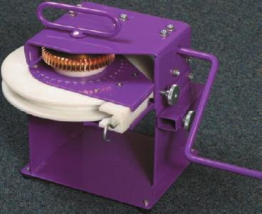
2 Instructions for the Compact Bending Tool for KS and CKS A Bending Strip B Guide Wedge C Bending Die (4 radius) D Metal Pin E Metal Housing F Measurement Line G Holder with Metal Protractor H Handle K Arrow A B C K D E Rear F G Necessary items: Art.number: Compact Bending tool KS - 60 cm (2 ) CKS 60 cm (2 ) Front H 1 2 Press Bending Strip (A) into slot of the KS-track, where you want to make a curve. Do not slide the strip in: this reduces the lifetime of the nylon strip. Insert the KS-track through the backside of the Compact Bending tool. To make a right hand curve, insert the track with the slot side up. To make a left hand or reversed curve, insert the track with the slot side down. 3 4 Insert the Guide-Wedge (B) firmly into the place between the metal part of the Bending Die (C) and the KS-track to position the track in the right place. Take the measurement of the first curve from the end of the Metal House (E) to the end of the track. This will create the distance from the outside of the track to the wall. Start curving by turning the handle (H) clockwise.
 points exactly to the required angle on the scale divider.")
 and place it against wall or on mal.")
 a few times anti-clockwise to release tension.")


3 5 6 Continue until the required angle has been reached. The Arrow (K) points exactly to the required angle on the scale divider. Turn a few degrees more to avoid spring back of the aluminium track. When angle is unknown, use the Metal Protractor (G) and place it against wall or on mal. The story of step two is not valid in this situation. 7 When the required curve is made, turn the handle (H) a few times anti-clockwise to release tension. Then, remove the Guide-Wedge, Metal Pin (D) and slide-out the Bending Die from the Metal Housing, together with the KS-track. 8 To make a second curve of 90 in the same KS-track, use a measurement lint from the outside of the track to the Measurement Line. This will create the distance from outside to outside of the two curves. 9 For curves, different then 90, use a reference point in the middle of the first curve. For the second curve, use the Measurement Line. This will create the distance from center to center of the two curves. 10 The Measurement Line (F) will be used for the exact measurement determination of the second curve. Same instructions can be used for bending DS. Only, use the DS Compact Bending tool (art.number: ) with the DS bending strips (art.numbers: and ).
 1060300000 CKS - 7 mtr.")

, so that slack between the Small Bending Dies (A) and the Compact Bending tool will be avoid.")
 with its slot facing up to make a right hand curve, or down to make a left hand curve.")
 a maximum time of five turns. Start turning the big handle of the Compact Bending tool to bend the track through the Continuous Curver.")
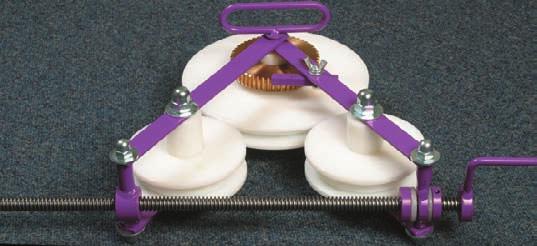
4 Instructions for the Continuous Curver for KS and CKS B C A Bending dies small B Bending die large C Metal pin D Unit stabilizer E Handle A D E Necessary items: Art.number: Continuous Curver KS - 7 mtr. (10 ) CKS - 7 mtr. (10 ) The Continuous Curver can be used when curves with a different radius other then 10 cm (4") have to be made, like bay windows, arches, bows and circles. If this happens frequently, consider the purchase of the Electric Bending Machine. 1 2 Remove the Metal Pin (C) and the regular bending die from the Compact Bending tool. Insert the Continuous Curver with the unit Stabilizer (D), so that slack between the Small Bending Dies (A) and the Compact Bending tool will be avoid. For determining necessary track length 3,14 x diameter of the circle. Add 10 cm (4 ) more on both ends. Insert the bending strip into the track. Place, the track between the Bending Dies (A and B) with its slot facing up to make a right hand curve, or down to make a left hand curve. Turn the small handle (E) a few times to avoid slack. 3 4 Mark the to be bend distance by reference points on the track. Turn the Small Handle (E) a maximum time of five turns. Start turning the big handle of the Compact Bending tool to bend the track through the Continuous Curver. Please, run the whole to be bend distance through the Continuous Curver until the reference points hit the first Small Bending Die (A), each time. The radius needs to be checked frequently. If the radius isn t still achieved, turn the Small Handle a few times more. Repeat this, until the required radius is created. It is possible to reverse the curve, once the radius is overbend.
 2560100000 A C D CCS 1 mtr.")


 and the Bending House (E).")
 to the end of the track.")
5 Instructions for the CS / CCS Bending Tool Necessary items: Art.number: B F E CS / CCS Bending Tool s CS 1 mtr (39 3/8") A C D CCS 1 mtr. (39 3/8") Can be used for bending CS and CCS with a radius of 20 cm (8"). Continuous curves will be made with the Electric Powered Bender. A Bending Die (6" radius) B Tab C Guide Wedge D Handle E Bending House F Measurement Line 1 2 First, insert the two smaller bending strips into the track. Then, press the bigger bending strip into the slot of the track between the smaller ones. Insert the track from the backside of the Bending tool, between the Bending Die (A) and the Bending House (E). Place the handle (D). F 3 4 Place the Guide-Wedge (C) like the picture shows. Slide the track in position and determine the required size from the measurement line (F) to the end of the track. This will create the distance from the outside of the track to the wall. Tighten the screw on the Guide-Wedge. Start bending by turning the handle until the required angle is reached. For two curves in one track, measure from the outside of the track to the measurement line (F). This will create the distance from the outside of the track between the two curves.
6 This is an example of bending a bay window with one track: KS or CKS 10" (25 cm) 10" (25 cm) 30" (100 cm) 30" (100 cm) 90" (300 cm) 1 Insert the track, measure and place metal protractor. 5 Insert the track again, measure and place metal protractor. 10" (1st curve) 90" (3rd curve) 2 6 (see metal protractor). (see metal protractor) " (4th curve) Insert the track again, measure and place metal protractor. Insert the track again, measure and place metal protractor. 30" (2nd curve) 4 8 (see metal protractor). (see metal protractor). If necessary shorten track to the size needed.
Bending Instructions
 Bending Instructions Forest Drapery Hardware P: 866-823-3894 F: 678.721.0023 www.forestdh.com Instructions Compact Bending Tool for KS, CKS, DS en CRS 20mm A Bending Strip B Guide Wedge (art nr: 9510000013)
INSTRUCTIONS. Scroll Collar and Zero Radius Block. DI-ACRO
 INSTRUCTIONS Scroll Collar and Zero Radius Block SCROLL COLLAR SET-UP INSTRUCTIONS DI-ACRO #1A BENDER Position the center hole of the scroll in the center on the mounting plate and pin in place using center
adaptivemechanical adaptive
 Mechanical clamping elements mechanical 6 Content Product group 6 Sliding clamp, mechanical 6.2210 Clamping block, mechanical 6.2212 High-pressure spindle, mechanical with integral wedge system 6.2270
MB-105 BENDER INSTRUCTION SET PRO-TOOLS 7616 INDUSTRIAL LANE TAMPA, FLORIDA PHONE FAX
 MB-105 BENDER INSTRUCTION SET PRO-TOOLS 7616 INDUSTRIAL LANE TAMPA, FLORIDA 33637-6715 813-986-9000 PHONE 813-985-6588 FAX ASSEMBLY INSTRUCTIONS IN THE FOLLOWING INSTRUCTIONS WE WILL EXPLAIN THE ASSEMBLY
STRONGMAN TOOLS SCROLL BENDERS
 STRONGMAN TOOLS SCROLL BENDERS Top- Large Scroll Bender Middle Medium Scroll Bender Bottom- Standard Scroll Bender with Banana Attachment. Scrolling Capacities (max) Std Scroller Flat Bar 40x5mm Square
COWO. Customer Wall Outlet. 1 General. 2 Kit content. 3 Handling of the box. TC-1203-IP Rev A, Apr
 COWO I N S T A L L A T I O N I N S T R U C T I O N TC-1203-IP Rev A, Apr 2017 www.commscope.com Customer Wall Outlet 1 General Customer Wall Outlet 2 Fiber for max. 2 bend reduced fibers, 2 SC-adapters
2. Refraction and Reflection
 2. Refraction and Reflection In this lab we will observe the displacement of a light beam by a parallel plate due to refraction. We will determine the refractive index of some liquids from the incident
JD 2. Model 6 Bender Setup and Operation Manual
 JD 2 Model 6 Bender Setup and Operation Manual JD Squared Inc. 1610 S.W. 18th Ave. Ocala, Florida 34474 USA (352) 351-3828, FAX (352) 351-4888 Internet Site: http://www.jd2.com Copyright 1999 by JD Squared
Basic Optics System OS-8515C
 40 50 30 60 20 70 10 80 0 90 80 10 20 70 T 30 60 40 50 50 40 60 30 70 20 80 90 90 80 BASIC OPTICS RAY TABLE 10 0 10 70 20 60 50 40 30 Instruction Manual with Experiment Guide and Teachers Notes 012-09900B
Tools: Sharpie, Square, Vise, Hack saw, Ruler, Punch, Hammer, File. 2. Cut the stock Place stock in vise and cut with hack saw
 Purpose: MAKE CATAPULT ARM Step 1 Tools: Sharpie, Square, Vise, Hack saw, Ruler, Punch, Hammer, File Materials: Flat aluminum ½ inch stock (see picture below) Gloves required 1. Pick up the aluminum ½
How to Install Custom Real Wood and Faux Wood Blinds
 Before you begin your installation: READ ALL INSTALLATION INSTRUCTIONS! Make sure that you have all tools and hardware needed for installation. Check the installation surface (wall, ceiling, or window
Installation Instruction
 Installation Step 1 Cut Upper Guide and Lower Tracks to opening size Step 2 Mount Upper Track to soffit or ceiling. Use appropriate mounting hardware for your field conditions. NOTE: The Lower Track is
IN20733 Rev. B 1/06/2016
 14,000 LBS. (6350 Kg.) Bolt-on Alignment Kit Installation Instructions S100129, S100130, S100131 S100132, S100133, S100134 S100135, S100136, S100137, S100173, S100174 Model Max Wheel Base Max 2 Wheel Alignment
Screw. Introduction This Rokenbok STEM-Maker lesson will use the following steps to learn about the screw. Learning Objectives. Resources.
 Screw Progression: Applications in Design & Engineering - Section 6 Curriculum Packet v2.0 Introduction This Rokenbok STEM-Maker lesson will use the following steps to learn about the screw. 1. Learn 2.
onlinecomponents.com
 Figure 1 PRO CRIMPER III Hand Crimping Tool Assembly 58603 1 consists of Die Assembly 58603 2 and PRO CRIMPER III Hand Tool Frame 354940 1. The die assembly consists of crimping dies and a locator assembly.
Patton Robotics ESRA II Expressive System for Robotic Animation
 Patton Robotics ESRA II Expressive System for Robotic Animation Assembly and Operation Instructions Version 1.0 Patton Robotics, LLC. 61 Hagan Drive New Hope, PA 18938 Copyright 2015 Patton Robotics, LLC.
Read these instructions thoroughly before crimping any contacts.
 PRO CRIMPER III Hand Crimping Tool Assembly 58583 1 consists of Die Assembly 58583 2 and PRO CRIMPER III Hand Crimping Tool Frame 354940 1. The die assembly consists of crimping dies and a locator assembly.
MODEL 3 TUBE BENDER. JD Squared Inc. Assembly & Operating Instructions. Copyright 2004 by J D Squared Inc.
 MODEL 3 TUBE BENDER Assembly & Operating Instructions JD Squared Inc. Copyright 2004 by J D Squared Inc. ASSEMBLY 1) The bender may be mounted to anything rigid enough not to twist or move during the bending
V-Groover SIMPLEX INSTRUCTION AND OPERATION MANUAL M O DEL 703. For best results use only authentic Logan blades.
 www.logangraphic.com SIMPLEX M O DEL 703 INSTRUCTION AND OPERATION MANUAL For best results use only authentic Logan blades CAUTION: BLADES EXTREMELY SHARP Use replacement blades #1258 Logan Graphic Products,
Instruction Guide 4A90L
 Instruction Guide 4A90L Kargo Master Rancho Cordova, CA 95742 800-343-7486 CustomerService@KargoMaster.com DATE: *PLEASE READ ALL INSTRUCTIONS AND WARNINGS PRIOR TO ASSEMBLING, INSTALLING, AND USING THIS
ABM International, Inc. Navigator Assembly Manual
 ABM International, Inc. 1 1.0: Parts List Tablet (Qty. 1) Tablet mount (Qty. 1) NOTE: Mount may appear and operate different then image below Control Box (Qty. 1) Motor Power Supply (Qty. 1) 2 X-axis motor
Profiform 200 Profiform 320. Operating manual
 Profiform 200 Profiform 320 Operating manual Profiform 200 / Profiform 320 Operating manual Page 1 Table of contents 1. General information Page 2 2. Profile of the Profiform sheet metal working machines
HMP-200 BENDER INSTRUCTION SET
 HMP-200 BENDER INSTRUCTION SET HMP-200 BENDER ASEMBLY INSTRUCTIONS STEP 1 STEP 2 BOLT LEFT SIDE PLATE TO BASE AS SHOWN WITH 1/2 x20 HEX BOLT & FLAT WASHER WELD BASE TO PLATE ON EACH SIDE NOTE: OFFSET HOLE
How to use. Use example. Non-scratch sheet prevents die marks. Tight-knit super fiber provides a working life of many hundreds cycles.
 How to use Small to Medium dies Fix Kizu-non on the die shoulder with masking tape. Should not be crinkled. *Cut Kizu-non with scissors for desired length. Large dies Fix Kizu-non on each die shoulders.
Intermediate+ Model 450 MAT CUTTER INSTRUCTION AND OPERATION MANUAL. 40" Mat cutting system with production stop, straight and bevel cutting heads
 Model 450 Intermediate+ 40" Mat cutting system with production stop, straight and bevel cutting heads MAT CUTTER www.logangraphic.com For best results use only authentic Logan blades INSTRUCTION AND OPERATION
SERVICE MANUAL MODEL: 13512, 14412, 15312
 SERVICE MANUAL MODEL: 13512, 14412, 15312 CONTENTS TROUBLESHOOTING... 1-3 SERVICE ACCESS (1) FACE COVER, BELT COVER... 4 SERVICE ACCESS (2) BASE PLATE... 5 SERVICE ACCESS (3) FRONT COVER... 6 SERVICE ACCESS
Home Electrical Wiring. Types of Receptacles and Wiring them for 120v 15Amp/20Amp
 Home Electrical Wiring Types of Receptacles and Wiring them for 120v 15Amp/20Amp Understanding the wires You have 3 wires in a home electrical system; Hot (Black wire) - dangerous one Neutral (White wire)
*Patent Pending. *Trademarked. Series II. Glass Conversion Kit. (888) One-Products (888)
 One-Products (888)") *Patent Pending *Trademarked Series II Glass Conversion Kit www.onepieceproducts.com (888) One-Products (888) 663-7763 Installation Manual Full One Piece Door Glass Conversion Kit Series II 1967-1972 Chevy
*Patent Pending *Trademarked Series II Glass Conversion Kit www.onepieceproducts.com (888) One-Products (888) 663-7763 Installation Manual Full One Piece Door Glass Conversion Kit Series II 1967-1972 Chevy
Operating Manual. for CUTTING, PERFORATING, BENDING SLB120
 Operating Manual for CUTTING, PERFORATING, BENDING SLB120 31040\B06eng 0896 0 Contents 1. Scope of delivery... 1 2. Technical specifications... 1 3. Applications... 1 4. Commissioning... 2 5. Cutting...
HQ Pole Upgrade Kit for HQ Adjustable Table and HQ QuilTable Assembly Instructions 1
 HQ Pole Upgrade Kit for HQ Adjustable Table and HQ QuilTable Assembly Instructions QF09775 The pole upgrade kit can be used with or without the QF09700 HQ Precison-Glide track upgrade kit. What s Included
Kit 102 Series Installation Instructions for Wood or Metal Posts on Level Runs
 Kit 102 Series Installation Instructions for Wood or Metal Posts on Level Runs A. Drill Posts Hole size for 1/8" or 3/16" cable installation This kit may also be used for stairs or runs that exit the end
Hats on the PR-620. The PR620 has two specialized hat frames to allow caps to be embroidered in a natural tubular fashion.
 How to set up the cap frame driver and the mounting jig are covered in these instructions. Learn hat loading, attaching the frame cap to the machine and screen settings for hats. Combine innovative designs
Operating & Maintenance Instructions 280 Hot Wire Sculptor
 Operating & Maintenance Instructions 280 Hot Wire Sculptor Table of Contents Assembly & Operation... 2 Electrical Supply and Connection... 8 Technical Specification... 8 Fault Finding... 8 Connection Diagram...
MIL-STD B (SH) UPDATE
 UPDATE") MIL-STD-2042-5B (SH) UPDATE Method 5A1 Insert Equipment and materials (to be added to table 5A1-I) Pliers 3.2.2.2 Cable and fiber preparation for Fiber Systems International backshells. Step 1: Ensure
MIL-STD-2042-5B (SH) UPDATE Method 5A1 Insert Equipment and materials (to be added to table 5A1-I) Pliers 3.2.2.2 Cable and fiber preparation for Fiber Systems International backshells. Step 1: Ensure
Calf-Tel Pen System Assembly Instructions
 Calf-Tel Pen System Assembly Instructions (Instructions work for 4, 6, and the 7 Pen Systems) 1 ASSEMBLY OF PEN FRONT AND WALLS START THE ASSEMBLY BY LINING UP THE TWO UNI-DIRECTIONAL ARROWS IN THE TOP,
WOLF LOOM DOUBLE BACK BEAM
 WOLF LOOM DOUBLE BACK BEAM Assembly Instructions Find out more at schachtspindle.com Schacht Spindle Company 6101 Ben Place Boulder, CO 80301 p. 303.442.3212 f. 303.447.9273 2017 Schacht Spindle Company,
Simplex Studio. Model 700-S MAT CUTTER INSTRUCTION AND OPERATION MANUAL
 Model 700-S Simplex Studio 22 1 /2" Mat cutting system with production stops, parallel mat guide, flush cut squaring arm, including straight and bevel cutting heads. MAT CUTTER www.logangraphic.com For
Thank you for purchasing out product! *Please read these instructions and follow them step by step. *
 Page 1 of 7 AD17 AA DS 4 X 16 T12 Thank you for purchasing out product! *Please read these instructions and follow them step by step. * STEP 1. Slide two support posts (REF. # 24) into the two outside
A. Preparing the fabric (not shown):
:") INSERTING ZIPPERS - CENTER INSERTION The zipper can be snapped on to the right or to the left side of the needle so that you can sew close to the zipper. When sewing on the right side of the zipper, attach
INSERTING ZIPPERS - CENTER INSERTION The zipper can be snapped on to the right or to the left side of the needle so that you can sew close to the zipper. When sewing on the right side of the zipper, attach
Installing the Exterior Cosmetics
 This chapter describes how to install the exterior cosmetics on the Cisco NCS 6000 LCC and includes the following topics: Overview of the Exterior Cosmetics, page Installing the Front Exterior Cosmetics,
Contents. 1 About The Radius Trim Bender
 User s Manual 9320 Evergreen Blvd.N.W. Suite G, Mpls. MN 55433 Phone 763-795-8885 Fax 763-795-8884 Toll Free 1-888-8 RADIUS (1-888-872-3487) Web Site: www.radiustrack.com E-Mail: info@radiustrack.com Contents
Product Instruction Booklet
 Product Instruction Booklet Contents: Page No. Pack Mount: This the set up that most people start with. 1 CARB Spout: Designed to reduce the chance of spilling as well as reducing the emissions of harmful
Classic Roll Tarp. Installation Instructions. Attention Dealers: Please give this owners manual to the customer when the product is delivered.
 Serving the Truck & Trailer Industry Since 1944 Classic Roll Tarp Attention Dealers: Please give this owners manual to the customer when the product is delivered. Call 800-535-9545 www.aeroindustries.com
RTI TECHNOLOGIES, INC.
 RTI TECHNOLOGIES, INC. BRC500 & BRC550 Arbor/Spindle Mechanism Adjustment & Service Technical Instructions The arbor/spindle mechanism of the BRC500/550 is designed to be robust for long life. Occasionally
CROWNARC. ARC Integrated Systems
 CROWNARC Screw your new CROWNARC to 2 pieces of 2 x 4 using the 4 holes. Then, mount the 2 x 4 s to the wall. You ll have best control when the CROWNARC is just above waist level. To crown a bow: Lay a
Arctic Equipment Manufacturing Corporation Arctic LD-P. Table of Contents
 Arctic LD-P Table of Contents Arctic Light Duty Poly Blade 78 & 84" (Blade, Quadrant & T-frame)....2 Installation of the Optional Spring...6 Installation of the Shoe Bracket...10 Power Angling Installation..........13
Figure A. Figure B. Figure C. Figure D
 Xsite 1 Power/Data Tile and Components Tools Required Tape Measure Cordless Drill/Driver #2 Phillips Screw driver bit Rubber Mallet Flat Blade Screwdriver Figure A Hardware Required Provided as shown Installation
Sentinel Series Cigar Humidor End Tables
 Sentinel Series Cigar Humidor End Tables Assembly Instructions Models: Sentinel 500, 1000 and 1500 Style: Traditional SENTINEL ASSEMBLY INSTRUCTIONS Congratulations! You have purchased a superior cigar
SCHACHT STANDARD FLOOR LOOMTM
 SCHACHT STANDARD FLOOR LOOMTM FL3109 FL3111 FL3113 FL3115 FL3121 FL3123 FL3125 FL3127 FL3310 FL3312 FL3314 FL3316 FL3322 FL3324 FL3326 FL3328 Assembly instructions LOW CASTLE LOOM IN MAPLE Find out more
Repairing Microsoft Wedge Touch Mouse Battery Cover Retaining Clip
 Repairing Microsoft Wedge Touch Mouse Battery Cover Retaining Clip Disassembly, repair and reassembly of Wedge Touch mouse when the battery cover will not stay closed. Also is a good guide to repair other
MULTI-ACTIVITY PLAY TABLE
 ASSEMBLY INSTRUCTIONS! WARNING: CHOKING HAZARD - Small parts. Not for children under 3 years.! CAUTION: Adult assembly required. C 2006 Melissa and Doug, Inc. All Rights Reserved www.melissaanddoug.com
Installation Instruction
 Installation Step 1 Cut Upper Guide and Lower Tracks to opening size Step 2 Mount Upper Track to soffit or ceiling. Use appropriate mounting hardware for your field conditions. NOTE: The Lower Track is
Slide the stock rubber tank mount caps onto the ends of the CS-1 tank mount:
 RYCA CS-1 BODY PARTS INSTALLATION GUIDE [The CS-1 installation guides should be used as supplements to the videos found on our Youtube Channel. There is no strict order to the build process, but it is
Quick Reference Guide
 9-Pin Dot Matrix Printer Quick Reference Guide Contents Loading Continuous Paper With the Front Push Tractor.................. 2 Loading Continuous Paper With the Rear Push Tractor.................. 4
 OPERATING INSTRUCTIONS www.bowforcearchery.com MAINTENANCE AND FINE TUNING Routinely grease the following with a premium bearing grease: The Extended Nut Fixture using the supplied grease fitting. The
ABM International, Inc.
 ABM International, Inc. Lightning Stitch required 1 1.0: Parts List head and motor assembly (Qty. 1) Reel stand (Qty. 1) Needle bar frame clamp (Qty. 1) Motor drive (Qty. 1) 2 Cable harness with bracket
V4 Premium Kit. Prusa i3 Build Guide
 V4 Premium Kit Prusa i3 Build Guide Hi! Congratulations on your purchase of the DIYElectronics.co.za Prusa I3 kit, the best South African 3D Printer Kit! Hopefully this should serve as complete guide to
Installation Operation Care
 Installation Operation Care Duette and Applause Honeycomb Shades SkyLift Lifting System with Manual Operation CONTENTS Getting Started: Product View... 1 Tools Needed... 2 Assembly: Arrange the Shade Components
METAL BENDER OPERATING & MAINTENANCE INSTRUCTIONS Model Nos: CCB1 & CCB2 Part Nos: & CCB2 CCB1
 METAL BENDER Model Nos: CCB1 & CCB2 Part Nos: 7630073 & 7630074 CCB2 CCB1 OPERATING & MAINTENANCE INSTRUCTIONS 1206 1 The Compact Bender allows you to economically make a variety of bends in flat, square,
FABA. Installation Instructions. Conductor Bar System. Publication #FABA-03 3/1/04 Part Number: Copyright 2004 Electromotive Systems
 FABA Conductor Bar System Installation Instructions Publication #FABA-03 3/1/04 Part Number: 005-1062 Copyright 2004 Electromotive Systems 1S 100 Z Installation Instructions Contents: Basic Diagram - -
v1.0 ASSEMBLY GUIDE Mia Wide Bookcase
 v1.0 ASSEMBLY GUIDE Mia Wide Bookcase Components Upon unpacking your bookcase from it s delivery box, you should have the pieces shown. Follow the steps on the next pages to assemble your new bookcase.
REQUIRED EQUIPMENT SETUP
 #003-598 raverhone VS OPERATION AND MAINTENANCE MANUAL 24V IMPORTANT NOTICE FOR OPERATORS No user serviceable parts inside. Do not remove any outer surfaces. Do not modify this equipment or remove warning
PORTA-DOCK, INC. AP17 APD DS 4 X 16 T12 AW17 CPD DS 4 X 16 T12
 Page 1 of 7 PORTA-DOCK, INC. AP17 APD DS 4 X 16 T12 AW17 CPD DS 4 X 16 T12 *For Beige Decking Add the Letter B to Model* Thank you for purchasing out product! *Please read these instructions and follow
ASSEMBLY MANUAL POLAR GRIPPERS
 ASSEMBLY MANUAL POLAR GRIPPERS 2012 TABLE OF CONTENTS TABLE OF CONTENTS... 2 PRESENTATION... 3 AMG GRIPPERS FOR ROBOTS... 4 PREPARATION OF THE PARTS... 5 PREPARING A MAIN BOOM... 6 PREPARING A SECONDARY
INSTALLING THE DRIVE SYSTEM
 In addition to the hardware kit that you received with the QBOT, you will need the hardware in this kit to complete the installation on your frame. The hardware kit for the NewJoy frame includes: (5) 1/4
MAT MASTER TM SYSTEMS
 FrameCo MAT MASTER TM SYSTEMS #14225 BEVEL MOUNT CUTTERS Welcome and thank you for purchasing a FrameCo Mat Master System. Through these instructions we will endeavour to show you the benefits of the system
TeacherGeek Launcher Example Build
 LAUNCHER EXAMPLE BUILD TeacherGeek Launcher Example Build TeacherGeek, 2011 LAUNCHER EXAMPLE BUILD TeacherGeek 2 LAUNCHER BASE PARTS A B D F E C G LAUNCHER EXAMPLE BUILD TeacherGeek 3 ASSEMBLING THE LAUNCHER
NEW. Perfect Fit Roller Blind System Measuring, assembly & fitting instructions
 NEW Perfect Fit Roller Blind System Measuring, assembly & fitting instructions Perfect Fit Roller Blind System Measuring, assembly & fitting instructions Clearance & seals Seal Check clearance around the
Tools for cables preparation
 Tools for cables preparation 2009 MEDIUM VOLTAGE CABLES 10,20,30 KV Cable preparation, 4 steps to a perfect joint with M-500 SET: 1. Removing of outer sheath 2. Peeling of semi-screen 3. Removing of insulation
ProFormer Professional Tubing Bender. Part #12485
 ProFormer Professional Tubing Bender Part #12485 Eastwood s ProFormer Professional Tubing Bender is designed around a rigid welded steel frame, iron/aluminum die and roller along with a 8 ton jack that
SIMPLEX STUDIO ELITE MAT CUTTER
 INSTRUCTION MANUAL MODEL 700- SIMPLEX STUDIO ELITE MAT CUTTER INSTRUCTIONS AND OPERATION MANUAL 0 inch (50 cm) capacity mat cutting system with bevel & straight cutters, production stops and squaring arm
Classic Roll Tarp. Installation Instructions. Attention Dealers: Please give this owners manual to the customer when the product is delivered.
 Serving the Truck & Trailer Industry Since 1944 Classic Roll Tarp Attention Dealers: Please give this owners manual to the customer when the product is delivered. Call 800-535-9545 www.aeroindustries.com
INS T A L L A TIO N INS T R U C TIO N S. Ceiling Mount Track System
 Ceiling Mount Track System 10.26.2016 Specifications Ceiling Post: Unassembled 2-7/8 Assembled 1-11/16 7/8 7-9/16 5-7/8 3/8 2 Tubes 1/2 2-3/8 5 Parts and Tools Tools Needed Tape Measure Pencil Drill with
Assembly instructions
 Nerdy Gurdy Assembly instructions This manual describes how to assemble a Nerdy Gurdy. Go to http://www.nerdygurdy.nl for more info about these instruments. Jaap Brand The Netherlands January 2018 General
Viewing the Ryca Motors CS-1 Build Video series at youtube.com/rycamotors is highly recommended before beginning the following assembly process.
 RYCA CS-1 ASSEMBLY GUIDE [The CS-1 installation guides should be used as supplements to the videos found on our Youtube Channel. There is no strict order to the build process, but it is highly recommended
Sentinel Series Cigar Humidor End Tables
 Sentinel Series Cigar Humidor End Tables Assembly Instructions Models: Sentinel 500, 1000 and 1500 Style: Contemporary SENTINEL ASSEMBLY INSTRUCTIONS Congratulations! You have purchased a superior cigar
Bendarc. Assembly Instructions. <<< Remove 5" pivot. Move the roller to the correct hole for your radius. (use 3/4" wrench)
") Bendarc Assembly Instructions
Bendarc Assembly Instructions
SIMPLEX ELITE MAT CUTTER
 INSTRUCTION MANUAL MODEL 750-1 / 760-1 SIMPLEX ELITE MAT CUTTER INSTRUCTIONS AND OPERATION MANUAL 40 in (101 cm) mat cutting system with bevel & straight cutters, production stops, 27 in (68 cm) squaring
aluminium profile system
 aluminium profile system 63 AME System aluminium profiles overview series profiles introduction 80x80 x80 x80/180 x Aluminium profiles are provided with longitudinal grooves which can be used in conjunction
GENERAL NOTES: Page 1 of 9
 Laminating A Zia Into A Turning Blank by W. H. Kloepping, Jan. 2009 This describes how a zia (the New Mexico state symbol) can be laminated into a turning blank. Materials needed: Square Turning Block
Mo d e l 32 Tu b e Be n d e r
 Mo d e l 32 Tu b e Be n d e r Assembly & Operating Instructions Hydraulic Version Mechanical Version J D Squared Inc. 2244 Eddie Williams Rd. Johnson City, TN 37601 (423) 979-0309, FAX (423) 979-2426 http://www.jd2.com
Assembly Instructions
 Unite Panel System Hinge Door July 2016 #12 x / slotted hex washer head bolt Figure 1 threshold bracket frame Detail F threshold bracket threshold bracket (installed) #12 x / slotted hex washer head bolt
Trade of Sheet Metalwork. Module 7: Introduction to CNC Sheet Metal Manufacturing Unit 7: CNC Setting & Operation Phase 2
 Trade of Sheet Metalwork Module 7: Introduction to CNC Sheet Metal Manufacturing Unit 7: CNC Setting & Operation Phase 2 Table of Contents List of Figures... 4 List of Tables... 5 Document Release History...
Slitter/E-Prom Upgrade for Duplo CC-228
 This Service Bulletin covers the upgrade of the Post Card Slitter and E-Prom for the Duplo CC-228 machines at Staples locations nationwide. Be sure to review and follow ALL of these instructions. Failure
Rorty No.2 Tube Bender.
 Copyright. This entire Manual is copyrighted to Rorty Design, with all rights reserved. No part may be transferred or copied by any means whatsoever, without the express written permission of Rorty Design.
Punching 3/16" diameter round hole in up to 3/16" thick (flat strip metal).
.") Wrought Iron Handicrafts, Inc. 3950 10 th Ave NW Rochester MN 55901-1336 507-289-0836 phone 800-456-7738 phone info@metalcraftusa.com email The ultimate dream machine for fabricators and ornamental metal
Wrought Iron Handicrafts, Inc. 3950 10 th Ave NW Rochester MN 55901-1336 507-289-0836 phone 800-456-7738 phone info@metalcraftusa.com email The ultimate dream machine for fabricators and ornamental metal
INSTALLATION AND CARE INSTRUCTIONS
 INSTALLATION AND CARE INSTRUCTIONS Vertical Applications Honeycomb Shades 52 C8-10-3401 Rev 2/14 CONTENTS Introduction...2 Before You Begin...3 Vertical Application Parts Overview...4 Materials Required...5
Panel building, focussed on dimensions. It s all in the inch. The DZUS rhythm...
 Panel building, focussed on dimensions. It s all in the inch First of all remember that (nearly) all dimensions in aircraft industry are based on imperial dimensions, so inches. This is the explanation
ROOF RACK INSTALLATION INSTRUCTIONS (35, 45, 55 RAIL LENGTHS)
") ROOF RACK INSTALLATION INSTRUCTIONS (35, 45, 55 RAIL LENGTHS) ROOF RACK INSTALLATION INSTRUCTIONS (35, 45, 55 RAIL LENGTHS) NOTE: Perrycraft s products are manufactured to be installed into the skin of
ROOF RACK INSTALLATION INSTRUCTIONS (35, 45, 55 RAIL LENGTHS) ROOF RACK INSTALLATION INSTRUCTIONS (35, 45, 55 RAIL LENGTHS) NOTE: Perrycraft s products are manufactured to be installed into the skin of
DIY Eliza: Instructions
 Make sure you first download from Redlightsonthebrain the list of things required for a DIY Eliza. 1. Take your bucket, ruler and marking pen. We will put on all the markings before we start cutting the
Quick Reference Guide
 9-Pin Dot Matrix Printer Quick Reference Guide Contents Loading Continuous Paper Onto the Front Push Tractor.................. 2 Loading Continuous Paper Onto the Rear Push Tractor.................. 4
A59 APD & A86 CPD 5'X 16' SW ALUMINUM PORTA-DOCK
 Page 1 of 5 PORTA-DOCK, INC. A59 APD & A86 CPD 5'X 16' SW ALUMINUM PORTA-DOCK *For Beige Decking Add the Letter B to model* Thank you for purchasing our product! *Please read these instructions and follow
REXIOUS SPINAL SYSTEM
 REXIOUS SPINAL SYSTEM SURGICAL TECHNIQUE www.diomedical.com. Site Preparation. Screw Insertion 3. Rod Preparation and Insertion 4. Rod Instruction 5. Set screw Insertion 6. Compression, Distraction & Rotation
CONTENTS LOCATE AND IDENTIFY THE PARTS... WIND THE BOBBIN... PREPARE YOUR TOP THREAD... STITCH SELECTOR / STITCH LENGTH/STITCH WIDTH CONTROLS...
 SERVICE MANUAL SEWING MACHINE MODEL 385. 15208400 OCTOBER, 2003 CONTENTS LOCATE AND IDENTIFY THE PARTS... WIND THE BOBBIN... PREPARE YOUR TOP THREAD... STITCH SELECTOR / STITCH LENGTH/STITCH WIDTH CONTROLS...
VS- 3 Hand Tool Kits , , and
 VS- 3 Hand Tool Kits 244271-1, 244271-5, and 244271-6 Instruction Sheet 408-7280 Jan 2017 PROPER USE GUIDELINES Cumulative Trauma Disorders can result from the prolonged use of manually powered hand tools.
INSTRUCTIONS FOR ASSEMBLING YOUR CLEARMOUNT MITER SAW SCALE
 INSTRUCTIONS FOR ASSEMBLING YOUR CLEARMOUNT MITER SAW SCALE Pictures shown are our SW7 but these instructions apply to all of our scales. Special information for other models is noted. ** Read & Follow
EURO CRATES EURO CRATE + FRONT ARCH (FLOOR MOUNT) (84 SIDES + EURO SWING BACK GATE)
 (84 SIDES + EURO SWING BACK GATE)") EURO CRATES CRATES-9 206352 84 EURO CRATE + FRONT ARCH (FLOOR MOUNT) (84 SIDES + SIDE MOUNT BUMPER) 206352-90 90 EURO CRATE + FRONT ARCH (FLOOR MOUNT) (84 SIDES + EURO SWING BACK GATE) 206350 84 EURO CRATE
EURO CRATES CRATES-9 206352 84 EURO CRATE + FRONT ARCH (FLOOR MOUNT) (84 SIDES + SIDE MOUNT BUMPER) 206352-90 90 EURO CRATE + FRONT ARCH (FLOOR MOUNT) (84 SIDES + EURO SWING BACK GATE) 206350 84 EURO CRATE
4700/4800 Series. Time Stamp. Handling Manual
 4700/4800 Series Time Stamp Handling Manual Proprietary Notice This document contains proprietary information and such information may not be reproduced in whole or part without the written permission
Application Tooling Specification Sheet
 HAND CRIMP TOOL Application Tooling Specification Sheet TYPE 4D Order No. 63825-8100 FEATURES A full cycle ratcheting hand tool ensures complete crimps Ergonomic soft grip handles for comfortable crimping
Video Wall Installation Instructions 2W X 3H, 3W X 3H
 Video Wall Installation Instructions 2W X 3H, 3W X 3H www.microndisplaysolutions.com Table of Contents Important Safety Instructions... 3 Configuration... 4 Package Contents, included and optional items...