ProFormer Professional Tubing Bender. Part #12485
|
|
|
- Christal Greer
- 6 years ago
- Views:
Transcription


1 ProFormer Professional Tubing Bender Part #12485

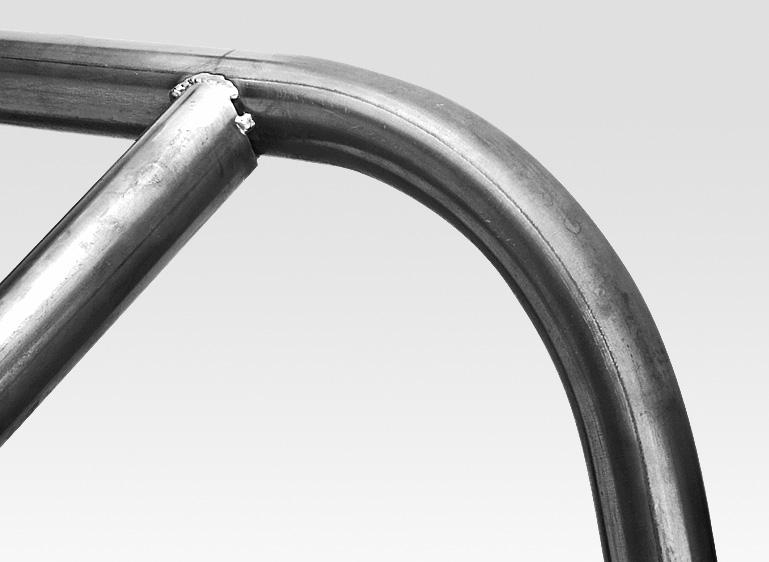
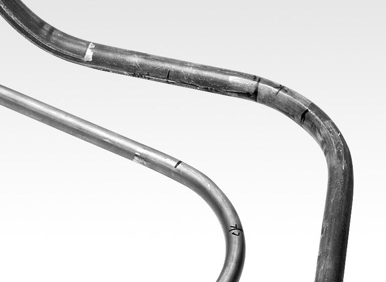
2 Eastwood s ProFormer Professional Tubing Bender is designed around a rigid welded steel frame, iron/aluminum die and roller along with a 8 ton jack that will handle up to 1.75 chromoly tubing in wall thickness. Our steel cage type frame offers secure usage while also focusing the bending force into the dies. The 8 ton jack effortlessly bends steel tubing with wall thickness up to Quick change dies allow you to work with multiple tubing diameters; dies change in minutes saving time and offering the flexibility to use one machine for various tubing sizes. While not all tube diameters and wall thickness can be bent a full 90 degrees, the machine will accurately bend 45 degrees pieces, which can easily be MIG/TIG welded to form 90 degree pieces. SAVE THIS MANUAL You will need this manual for its safety warnings and precautions, assembly instructions, operating and maintenance procedures, parts list and diagram. Keep your invoice with this manual. Keep this manual and invoice in a safe and dry place for future reference. 2 Copyright 2010 Easthill Group, Inc. Printed in the United States of America

. 2.")

3 SET UP BEFORE BEGINNING ANY WORK WITH THIS TOOL, IT IS ABSOLUTELY NECESSARY THAT IT BE SECURELY BOLTED TO A FLOOR OR A HEAVY, STURDY WORKBENCH. WARNING: THIS TOOL CAN NOT BE OPERATED WITHOUT ADEQUATE SUPPORT OR SEVERE PERSONAL INJURY OR DAMAGE CAN OCCUR. 1. Be sure there is suffi cient working room around the tool to allow for safe handling of various lengths of tubing. 2. Note that the unit is shipped with the 1 Die & Roller set installed. To work with 1 tubing, go to the Operation section of these instructions. INSTALL 3/4 OR 1-1/2 DIES AND ROLLERS 1. Pull Retaining Pin from Lower Roller Shaft, remove shaft and Roller Die (Fig. A). 2. Loosen and remove 2 socket head cap screws from Forming Die face with a 5/16 hex key wrench (Fig. B). 3. Place the selected size Forming Die over the Die Block, replace the 2 socket head cap screws and tighten with a 5/16 hex key wrench. 4. Holding the selected size Roller Die (matched to Forming Die size), slide Roller Die Shaft through the upper of two frame holes, through the Roller Die then through opposite hole in frame (Fig. C). 5. Replace retaining pin. FIG. A FIG. B FIG. C Roller die To order parts and supplies, call or visit 3
. 2.")
.")

. 7.")
4 INSTALL LARGER 1-5/8 OR 1-3/4 DIES AND ROLLERS Disassembly For Removal 1. Pull Retaining Pin from Lower Roller Shaft, remove shaft and Roller Die. (Fig. D). 2. Place Jack Handle through the triangular openings of the frame toward the angled side and in front of the Jack Pivot Pin (Fig D.). 3. While supporting the Die Block with your opposite hand, remove Retaining Pin and Shaft from Frame and Die Block (Fig. E.). CAUTION: the Die Block assembly is heavy. 4. Continue to support the Die Block with your hand while removing the Jack Pivot Shaft Retaining Pin and Shaft from the Jack Base (Fig. F). 5. The Die Block will be free and The Jack will now be supported by hanging from the Tension Spring. 6. Loosen and remove 2 socket head cap screws from Forming Die face with a 5/16 hex key wrench (Fig. G). 7. Place the selected size Forming Die over the Die Block, replace the 2 socket head cap screws and tighten with a 5/16 hex key wrench. FIG. D FIG. E FIG. F FIG. G 4 Copyright 2010 Easthill Group, Inc. Printed in the United States of America


, slide Roller Die Shaft through the upper of two frame holes,")
5 Reassembly 1. Be sure the Top Pad of the Jack post is in place in the Socket at the top of the Frame (Fig H.). 2. While supporting the Die Block in your hand, Slide the Die Block Shaft through the hole in the Frame, through the Die Block and through the opposite Frame hole (Fig. I). Replace Retaining Pin. 3. Keep the Die Block rotated in the up position and slide the Jack Pivot Shaft through the Jack Base and Die Block (Fig J.) then replace Retaining Pin. 4. Holding the selected size Roller Die (matched to Forming Die size), slide Roller Die Shaft through the upper of two frame holes, through the Roller Die then through opposite hole in frame (Fig. K). Replace Retaining Pin. FIG. H FIG. I FIG. J FIG. K To order parts and supplies, call or visit 5

6 TUBING LAYOUT DATA Use this chart when laying out your project to help determine the amount of tubing needed. The following fi gures are representative of the average linear amount of tubing required for a given size and the bend radius it will yield at a maximum angle of 90. Please note that 90 is not achievable on all tubing and is dependant upon the particular wall thickness, diameter and hardness of the tubing used. These fi gures are for the Length of the bend portion only. An additional 1-1/2 of straight section per bend is required as it is clamped in the Die Block. Tubing Layout Length Chart Size Bend Radius /4 5-5/16 8-1/8 5-1/2 4-1/16 2-3/ /8 8-1/2 5-5/8 4-1/4 2-7/8 2-1/8 1-1/2 5-7/16 9-3/8 6-1/4 4-3/4 3-1/8 2-3/8 1-5/8 6-1/2 10-1/4 6-3/4 5-1/8 3-3/8 2-5/8 1-3/4 6-5/8 10-3/8 6-7/8 5-3/8 3-1/2 2-3/4 TUBING BEND LOCATION MEASURING DATA The following chart provides a means to measure your tubing before bending to determine the location of the center of the bend. The dimensions below are applied to a straight section of tubing. You simply place a mark on the tubing exactly where you want the center of the fi nal bend to be, then measure back and place a second mark on the tubing with the appropriate dimension taken form the chart below (Fig. L). The second mark is aligned with the outward face of the Clamping Loop (Fig. N). Please keep in mind that these dimensions are approximate and will vary based on the wall thickness and hardness of the particular tubing being used. Thinner, softer tubing may require less length while thicker or harder tubing may require slightly more length. FIG. L FIG. M Align with face of Clamping Loop 1-1/2 Before Bend Location Measuring Chart Size /4 5-1/8 4-1/4 3-5/ / /4 4-3/8 3-3/4 3-1/8 2-3/8 1-1/2 6-1/4 4-3/ /4 2-3/4 1-5/8 6-5/ /8 3-3/8 2-7/8 1-3/4 6-3/4 5-1/8 4-1/4 3-1/2 3 After 6 Copyright 2010 Easthill Group, Inc. Printed in the United States of America


7 OPERATION 1. BEFORE BEGINNING ANY WORK WITH THIS TOOL, it is absolutely necessary that it be securely bolted to a fl oor or a heavy, sturdy workbench. FIG. N Clamping screw This tool can not be operated without adequate support or severe personal injury or damage can occur. 2. It is extremely important to practice bending several pieces of tubing in each size used in your project. This will allow you to become familiar with the tool and the particular limitations of the tubing being used. 3. It is highly recommended to have the Tubing Bender mounted to a level surface and use a magnetic angle fi nder to check your progress. 4. Using the Bend Location Measuring Chart on previous page, place a mark on your section of tubing at a point where you want to begin. 5. Place Tubing between the Die Block and Roller Dies and extend through the Hold Down Clamp (Fig. N). 6. Align your previously made mark with the leading edge of the Hold Down Clamp. Tighten the Clamping Screw (Fig. N). Tighten suffi ciently to hold clamp securely, being careful not to over-tighten and crush tubing. 7. Make sure the Jack Rod is in the fully retracted position and the valve is closed. NOTE: Place the notch of the Jack Handle over the T fi tting on the Jack, (open is Counter Clockwise, closed is Clockwise). 8. Place the Jack Handle in the receptacle and VERY SLOWLY pump the Jack rotating the Die Block and bending the tubing. 9. At some point during the forming process, the jack will reach the limit of its travel (Fig. O). At that point, release the jack valve slightly to reduce some pressure then place the jack handle through the square window of the frame and through the nearest hole in the Die Block (Fig. P). Pry downward against spring tension and pull the Jack post out of the Socket. Thread the post outward to extend jack travel then replace the jack rod in the socket, remove the jack rod from the window and close the valve. 10. Resume jacking until the desired angle is achieved. For some alloys, it FIG. O FIG. P Clamping loop Jack handle may be necessary to bend several degrees beyond your desired fi nal angle to allow for springback. A magnetic angle fi nder is very helpful for this process. 11. When complete, release the jack valve, loosen the Hold Down Clamp bolt and remove the pin (Fig. N). To fully free the tubing, it may be necessary to utilize the procedure in step 10 and remove the jack post from the frame and pull the Jack post from the Socket. You are now ready to create professional tubing bends enabling you to create projects in steel tubing to your individual design. To order parts and supplies, call or visit 7
8 NOTES If you have any questions about the use of this product, please contact The Eastwood Technical Assistance Service Department: The Eastwood Company 263 Shoemaker Road, Pottstown, PA 19464, USA US and Canada: Outside US: fax: Instruction Manual #12485Q - Rev. 5/10
PAN AND BOX BRAKE INSTRUCTIONS. Item #20649
 PAN AND BOX BRAKE INSTRUCTIONS Item #20649 The EASTWOOD 12 & 24 PAN AND BOX BRAKES are precision engineered metal working tools designed to produce accurate, variable length bends in angles up to 135 in
4" METAL BENDER INSTRUCTIONS. Part #20521
 4" METAL BENDER INSTRUCTIONS Part #20521 The EASTWOOD 4 METAL BENDER is a high quality, industrial style tool capable of generating a powerful 2-1/2 tons of pressing force to create 90 or lesser repeatable
Item # HigH-CapaCity tubing bender INSTRUCTIONS
 Item #21115 HigH-CapaCity tubing bender INSTRUCTIONS Your Eastwood High-Capacity Tubing Bender is a high quality, precision tool capable of creating accurate, smooth, kink-free bends up to 180 in aluminum,
8" BENCH SHEAR INSTRUCTIONS. Item #20198
 8" BENCH SHEAR INSTRUCTIONS Item #20198 Your EASTWOOD 8 BENCH SHEAR for metal cutting is designed for quickly and cleanly cutting mild steel, aluminum and other metals. Torque-amplifying, compound linkage
Item #28187 EASTWOOD BEAD ROLLER INSTRUCTIONS
 Item #28187 EASTWOOD BEAD ROLLER INSTRUCTIONS The Eastwood Bead Roller is a professional metal fabrication tool for producing strengthening ribs in panels used in creating replacement fl oor pans, fi rewalls,
HYDRAULIC FLARING TOOL
 Item #31562 HYDRAULIC FLARING TOOL INSTRUCTIONS The FAIRMOUNT HYDRAULIC FLARING TOOL provides the ability to produce repeatable, perfect, OE-precision brake and fuel line flares in steel and soft-metal
Item #20622 MOTORIZED BEAD ROLLER INSTRUCTIONS
 Item #20622 MOTORIZED BEAD ROLLER INSTRUCTIONS The Eastwood Motorized Bead Roller is a professional metal fabrication tool. It is excellent for producing strengthening ribs in replacement fl oor pans,
HMP-200 BENDER INSTRUCTION SET
 HMP-200 BENDER INSTRUCTION SET HMP-200 BENDER ASEMBLY INSTRUCTIONS STEP 1 STEP 2 BOLT LEFT SIDE PLATE TO BASE AS SHOWN WITH 1/2 x20 HEX BOLT & FLAT WASHER WELD BASE TO PLATE ON EACH SIDE NOTE: OFFSET HOLE
MIG / TIG / PLASMA WELDING CART
 MIG / TIG / PLASMA WELDING CART INSTRUCTIONS Part #11616 This welding cart was designed by The Eastwood Company to make storage, accessibility, and maneuverability of your welders easier than ever before.
Hydraulic Clamp Carrier. Installation & Operation Manual
 Hydraulic Clamp Carrier Installation & Operation Manual Hydraulic Clamp Carrier Installation & Operation Manual Quick Machinery Company 8272 Peninsula Drive Kelseyville, CA 95451 phone: (707) 272-6719
METAL BENDER OPERATING & MAINTENANCE INSTRUCTIONS Model Nos: CCB1 & CCB2 Part Nos: & CCB2 CCB1
 METAL BENDER Model Nos: CCB1 & CCB2 Part Nos: 7630073 & 7630074 CCB2 CCB1 OPERATING & MAINTENANCE INSTRUCTIONS 1206 1 The Compact Bender allows you to economically make a variety of bends in flat, square,
MM750 Installation Instructions
 MM750 Installation Instructions IMPORTANT SAFETY INSTRUCTIONS - SAVE THESE INSTRUCTIONS Please read this entire manual before you begin. Do not unpack any contents until you verify all requirements on
Bendarc. Assembly Instructions. <<< Remove 5" pivot. Move the roller to the correct hole for your radius. (use 3/4" wrench)
") Bendarc Assembly Instructions
Bendarc Assembly Instructions
MODEL W1.0X305A(12 ) MODEL W1.0X610A(24 ) HAND BENDING BRAKE ASSEMBLY&OPERATING INSTRUCTION
 MODEL W1.0X610A(24 ) HAND BENDING BRAKE ASSEMBLY&OPERATING INSTRUCTION") MODEL W1.0X305A(12 ) MODEL W1.0X610A(24 ) HAND BENDING BRAKE ASSEMBLY&OPERATING INSTRUCTION 1 SAVE THIS MANUAL You will need the manual for the safety warning and precautions, assembly instructions, operating
MODEL W1.0X305A(12 ) MODEL W1.0X610A(24 ) HAND BENDING BRAKE ASSEMBLY&OPERATING INSTRUCTION 1 SAVE THIS MANUAL You will need the manual for the safety warning and precautions, assembly instructions, operating
SWAG AIR-HYDRO RAM MOUNT ASSEMBLY INSTRUCTIONS
 SWAG AIR-HYDRO RAM MOUNT ASSEMBLY INSTRUCTIONS Tools needed for assembly: 5/16 HEX KEY WRENCH ¼ HEX KEY WRENCH ¾ SOCKET AND WRENCH 1.125 SOCKET HAMMER FLAT SCREW DRIVER GREASE FOR ASSEMBLY Step #1 Disassemble
MM340 Installation Instructions IMPORTANT SAFETY INSTRUCTIONS - SAVE THESE INSTRUCTIONS
 MM30 Installation Instructions IMPORTANT SAFETY INSTRUCTIONS - SAVE THESE INSTRUCTIONS Please read this entire manual before you begin. Do not unpack any contents until you verify all requirements on PAGE.
SAFETY INSTRUCTIONS. Wear protective clothing, including safety glasses and steel toe boots.
 SAFETY INSTRUCTIONS Wear protective clothing, including safety glasses and steel toe boots. DO NOT allow loose clothing or long hair near machine operations. Keep work site and machine clean. Use brush
BEAST THE. Tube and Pipe Notcher Operating Instructions. Notches In Bends Straight Notches. Angled Notches. Offset Notches
 Copyright (c) 2007 J D SQUARED INC. www.jd2.com THE BEAST Tube and Pipe Notcher Operating Instructions Notches In Bends Straight Notches Angled Notches PATENT PENDING Offset Notches Assembly After unpacking
MM540 Installation Instructions IMPORTANT SAFETY INSTRUCTIONS - SAVE THESE INSTRUCTIONS
 MM50 Installation Instructions IMPORTANT SAFETY INSTRUCTIONS - SAVE THESE INSTRUCTIONS Please read this entire manual before you begin. Do not unpack any contents until you verify all requirements on PAGE.
The Bowflex Revolution XP Home Gym Assembly Instructions. P/N: Rev ( /0 )
") P/N: 001-7057 Rev ( /0 ) The Bowflex Revolution XP Home Gym Assembly Instructions 2 Table of Contents Before You Start... 2 Tools You Will Need / Hardware Contents... 3 Box Contents... 6 Assembling Your
P/N: 001-7057 Rev ( /0 ) The Bowflex Revolution XP Home Gym Assembly Instructions 2 Table of Contents Before You Start... 2 Tools You Will Need / Hardware Contents... 3 Box Contents... 6 Assembling Your
MUELLER. Improved, Centurion Series, Modern Improved, and 107. Fire Hydrants. Inserting Extension Sections. Reliable Connections
 insertion Instructions manual MUELLER Improved, Centurion Series, Modern Improved, and 107 table of contents PAGE Centurion Series Fire Hydrant Adding an Extension 2-3 Improved Fire Hydrant Inserting Extension
southpaw enterprises, inc.
 southpaw enterprises, inc. Store these instructions with the enclosed maintenance checklist in a safe place. You may also access them on our website. Instruction Sheet Wood Joist 2-1/2 Ft. Drop Ceiling
LPK1550 Hydraulic Crimping Tool 15-ton
 SERVICE MANUAL LPK1550 Hydraulic Crimping Tool 15-ton Serial Code FYF Read and understand all of the instructions and safety information in this manual before operating or servicing this tool. Register
KIT. Assembly Instructions. HayDay, LLC
 KIT Assembly Instructions HayDay, LLC 1-800-732-1654 www.stablegrazer.com Read completely through the assembly instructions before starting assembly. The Stable Grazer Kit comes in two boxes. Remove all
Assembly & Disassembly Guide
 Carvable Jaw Block Assembly & Disassembly Guide quincy\prod. Setup info\jawkits\jawkit setup guide P/N CARV-95, REV C 02/18/03 Index: Page Revision History... 1 Sec. Carvlock/ Fixture Vise 1.0 Jaw Block
Retractable Tongue Kit Model MPG457 Instructions
 Malone MicroSport Trailer Retractable Tongue Kit Model MPG457 Instructions TM Take a few moments and read through these instructions to familiarize yourself with the step by step assembly process before
Auto-Spreader Spreader HS10K Hydraulic Flange Spreader
 Auto-Spreader Spreader HS10K Hydraulic Flange Spreader US Patent No. 5678293 Operation and Maintenance Manual Keep For Your Records Contents Operation...2 Maximum Spreader Extension...3 Safety Tips...4
Lumber Smith. Assembly Manual. If you are having problems assembling the saw and need assistance, please contact us at:
 Lumber Smith Assembly Manual If you are having problems assembling the saw and need assistance, please contact us at: 804-577-7398 info@lumbersmith.com 1 Step 1 Safety Carefully read the Owners Manual.
MODEL T10050 RIGHT ANGLE IRON BENDER INSTRUCTIONS
 MODEL T10050 RIGHT ANGLE IRON BENDER INSTRUCTIONS Damage to your eyes, face, and hands could result from using this item without proper protective gear, such as safety glasses or a face shield, and gloves.
Replacing the build plate clamps
 Repair manual Replacing the build plate clamps Instructions The build plate clamps hold the glass plate in place on the heated bed. There are two fixed in place at the back of the heated bed and two at
Rhino Packing Gland Tool
 Instruction Sheet P/N Rhino Packing Gland Tool 1. Description See Figure 1. The Rhino packing gland tool is used to remove the packing gland from Rhino bulk unloader pumps. The tool consists of two components,
southpaw enterprises, inc.
 southpaw enterprises, inc. Instruction Sheet C-STAND 7100 Store these instructions in a safe place or with the enclosed maintenance checklist Take time to familiarize yourself with the use and maintenance
Operating, Servicing, and Safety Manual Model # 100 Standard Hydraulic Tubing Notcher Model #100-U Heavy Duty Hydraulic Tubing Notcher
 Operating, Servicing, and Safety Manual Model # 100 Standard Hydraulic Tubing Notcher Model #100-U Heavy Duty Hydraulic Tubing Notcher Model # 100 Standard Model #100-U Heavy Duty CAUTION: Read and Understand
1801 Ratchet Bender For 1-1/4", 1-1/2" Rigid Conduit, IMC and Schedule 40 Pipe
 INSTRUCTION MANUAL 1801 Ratchet Bender For 1-1/4", 1-1/2" Rigid Conduit, IMC and Schedule 40 Pipe Serial Code RS Read and understand all of the instructions and safety information in this manual before
MB-105 BENDER INSTRUCTION SET PRO-TOOLS 7616 INDUSTRIAL LANE TAMPA, FLORIDA PHONE FAX
 MB-105 BENDER INSTRUCTION SET PRO-TOOLS 7616 INDUSTRIAL LANE TAMPA, FLORIDA 33637-6715 813-986-9000 PHONE 813-985-6588 FAX ASSEMBLY INSTRUCTIONS IN THE FOLLOWING INSTRUCTIONS WE WILL EXPLAIN THE ASSEMBLY
Profiform 200 Profiform 320. Operating manual
 Profiform 200 Profiform 320 Operating manual Profiform 200 / Profiform 320 Operating manual Page 1 Table of contents 1. General information Page 2 2. Profile of the Profiform sheet metal working machines
MantelMount. TM1A Installation Instructions IMPORTANT SAFETY INSTRUCTIONS - SAVE THESE INSTRUCTIONS
 MantelMount TMA Installation Instructions IMPORTANT SAFETY INSTRUCTIONS - SAVE THESE INSTRUCTIONS TM Thank you for choosing the MantelMount television wall mount. Please read this entire manual before
MUELLER. Improved, Centurion Series, Modern Improved, and 107. Fire Hydrants. Inserting Extention Sections. Reliable Connections
 insertion Instructions manual MUELLER Improved, Centurion Series, Modern Improved, and 107 table of contents PAGE Centurion Series Fire Hydrant Adding an Extention 2-3 Improved Fire Hydrant Inserting Extention
Pneumatic Clamp Carrier. Installation & Operation Manual
 Pneumatic Clamp Carrier Installation & Operation Manual Pneumatic Clamp Carrier Installation & Operation Manual Quick Machinery Company 8272 Peninsula Drive Kelseyville, CA 95451 phone: (707) 272-6719
YALE FIGURE 500 & 500R CLOSURE OPERATION AND MAINTENANCE INSTRUCTIONS
 YALE FIGURE 500 & 500R CLOSURE OPERATION AND MAINTENANCE INSTRUCTIONS IMPORTANT INFORMATION Note To Supervisor: Please share this information with your employees and make sure they have received training
CarvLock HDLM6 Manual Machinable Jaw Vise
 CarvLock HDLM6 Manual Machinable Jaw Vise Instructions KURT MANUFACTURING INDUSTRIAL PRODUCTS DIVISION 1325 QUINCY STREET NE MINNEAPOLIS, MN. 55413 TOLL FREE: (800) 328-2565 TEL: (763) 572-4424 FAX: (612)
MODEL SK61732 COMPRESSOR SERVICE KIT
 MODEL SK61732 COMPRESSOR SERVICE KIT For use on 607 and 617 Model Compressors with.32 Stroke WARNING: Unplug the compressor before beginning disassembly. CAUTION: Improper assembly or use of damaged parts
w w w. h d o n l i n e s h o p. d e TIMKEN BEARING CONVERSION TOOL GENERAL INSTALLATION -J04672 REV Kit Number Models
 -J067 REV. 008-07- GENERAL Kit Number 8-08 Models TIMKEN BEARING CONVERSION TOOL For model fitment information, see the P&A Retail Catalog or the Parts and Accessories section of www.harley-davidson.com
MODEL 83 Pail Handler
 MORSE MFG. CO., INC. 727 West Manlius Street P.O. Box 518 East Syracuse, NY 13057-0518 Phone: 315-437-8475 Fax: 315-437-1029 Email: service@morsemfgco.com Website: www.morsemfgco.com COPYRIGHT 2005 MORSE
Pneumatic Clamp Carrier. Installation & Operation Manual
 Pneumatic Clamp Carrier Installation & Operation Manual Pneumatic Clamp Carrier Installation & Operation Manual Quick Machinery Company 8272 Peninsula Drive Kelseyville, CA 95451 phone: (707) 272-6719
V-MOTION LITE USER GUIDE. Rat Rig All rights reserved.
 V-MOTION LITE USER GUIDE Rat Rig 2017. All rights reserved. PACKAGE CONTENTS 1 1x V-Motion Motor 2 1x Belt 3 1x 3mm Hex Key 4 1x AA Battery Pack (for 8x AA batteries)* 5 1x V-Motion Controller 6 2x Knob
WEIGHT ADJUSTABLE ESPREE. Model 2ESP-WA-C48- Model 2ESP-WA-C60- 2ESP-WA Rev B 8/17 ASSEMBLY AND OPERATION
 WEIGHT ADJUSTABLE ESPREE PNEUMATIC TABLE BASE 2ESP-WA Rev B 8/17 Model 2ESP-WA-C48- Model 2ESP-WA-C60- = SLV, BLK or WHT ASSEMBLY AND OPERATION PARTS AND TOOLS PLEASE REVIEW these instructions before beginning
Hollywood Swing Away 2 and 4 Bike Racks Assembly and Installation Guide
 Hollywood Swing Away 2 and 4 Bike Racks Assembly and Installation Guide Tools Required: two adjustable wrenches, pliers, ¾ socket wrench recommended Note: please do assembly near your vehicle as you Can
LMI Bending Machine. Photo 1. Photo 2. Photo 3. Photo 5. Photo 4
 LMI Bending Machine Watch the instructional DVD shipped with the LMI Bending Machine prior to assembling or using it. Note the bending head assembly has been changed since these photos were taken. Operationally
INSTALLATION TORSION SPRING FRONT OR REAR MOUNT LOW HEADROOM. 1 Cutting Vertical Track. 2 Fully Adjustable Jamb Brackets
 TORSION SPRING FRONT OR REAR MOUNT LOW HEADROOM Wayne Dalton, a division of Overhead Door Corporation P.O. Box 67, Mt. Hope, OH., 44660 Supplemental insert Copyright 2015 Wayne Dalton, a division of Part
52/8 04/2005 UNIVERSAL. Narrow Stitching Head. Operating-Instructions Spare parts list
 Operating-Instructions Spare parts list UNIVERSAL 52/8 04/2005 Narrow Stitching Head hohner Maschinenbau GmbH Gänsäcker 19, 78532 Tuttlingen, Telephone 07462 / 9468-0, Fax 07462 / 9468-20 hohner Maschinenbau
MODEL T21973 METAL BLADE GUIDE SET INSTRUCTIONS
 MODEL T21973 METAL BLADE GUIDE SET INSTRUCTIONS Introduction (Figure 1) These Euro-style blade guides replace the blade guides on the G0531, G0531B, G0566, G0568, and G0569 bandsaw. Tools Needed Wrench
Power Train Lift Max. Capacity: 1,250 lbs.
 655 EISENHOWER DRIVE OWATONNA, MN 55060 USA PHONE: (507) 455-7000 TECH. SERV.: (800) 533-6127 FAX: (800) 955-8329 ORDER ENTRY: (800) 533-6127 FAX: (800) 283-8665 INTERNATIONAL SALES: (507) 455-7223 FAX:
TorqueMaster Replacement Spring
 TorqueMaster Replacement Spring Installation Instructions NOTE: Use these installation instructions in conjunction with the TorqueMaster Repair / Replacement Spring Program literature. Copyright 999 Wayne-Dalton
Assembly Instructions
 P/N 8650/8655 Assembly Instructions NOTE: Your Sherline CNC Cam Grinder is double boxed and secured to a wooden shipping frame. Upon delivery, check the outer box for damage. If the box is damaged, take
STRONGMAN TOOLS SCROLL BENDERS
 STRONGMAN TOOLS SCROLL BENDERS Top- Large Scroll Bender Middle Medium Scroll Bender Bottom- Standard Scroll Bender with Banana Attachment. Scrolling Capacities (max) Std Scroller Flat Bar 40x5mm Square
model tsa-sa48 Sliding Crosscut Table installation guide
 model tsa-sa48 Sliding Crosscut Table installation guide A Note About Color Variations Among Anodized Aluminum Components Congratulations on the purchase of this SawStop Sliding Crosscut Table. We at SawStop
Operation and Service Instructions With Replacement Parts List
 No. 700-F TUBE BENDER Operation and Service Instructions With Replacement Parts List Warning! Keep body parts away from pinch/bend areas while using. Ensure tubing is secure in tool before bending. Always
MPA-9000 Universal Ceiling Projector Mount Kit
 I N S T R U C T I O N M A N U A L Universal Ceiling Projector Mount Kit The Universal Ceiling Projector Mount provides a unique, simplified method of ceiling mounting your inverted projector. This low
.00025" PER CLICK. As you turn the adjustment screw you should be able to feel a click. Each click will change the part diameter.00025".
 ULTRA PRECISION DIAMETER ADJUSTMENT.00025" PER CLICK The ultra precision diameter adjustment is extremely accurate, as well as, quick and easy to use. The adjustment mechanism is spring loaded to take
LifeGear G1 /HOME GYM ITEM NO.: 63100
 LifeGear G1 /HOME GYM ITEM NO.: 63100 OWNER S MANUAL IMPORTANT: Read all instructions carefully before using this product. Retain this owner s manual for future reference. The specifications of this product
OPERATION, SERVICE AND PARTS INSTRUCTION MANUAL 1813 BENDING TABLE FOR 881 HYDRAULIC BENDER
 OPERATION, SERVICE AND PARTS INSTRUCTION MANUAL 1813 BENDING TABLE FOR 881 HYDRAULIC BENDER Read and understand this material before operating or servicing this bender. Failure to understand how to safely
Signature Choral Riser Side Rail
 Assembly/Owner s Manual Signature Choral Riser Side Rail Signature Choral 3-Step Riser with Optional Side Rail Signature Choral 4-Step Riser with Optional Side Rail CONTENTS Visit the Signature Choral
Model 54 Bender Assembly and Operating Instruction Manual
 Model 54 Bender Assembly and Operating Instruction Manual Revision Date: 4/28/2015 JD Squared Inc. 2244 Eddie Williams Rd. Johnson City, TN 37601 USA (423) 979-0309 Copyright 2014 by JD Squared Inc. Table
Adjusting Ibanez SR405QM Truss Rod
 Adjusting Ibanez SR405QM Truss Rod High tension caused by the strings can cause the wood of the fret board to bow. This bowing can become so extreme it becomes difficult or impossible to play on due to
INSTRUCTIONS 360 CHAINROLL
 INSTRUCTIONS 360 CHAINROLL 360 CHAINROLL REGISTRATION Please visit productregistration.360yieldcenter.com to complete the product registration for your 360 CHAINROLL so we can better support our products
4.4 PUMP MAINTENANCE MODELS: DB, DC, DF, DG, DJ, DL
 4.4 PUMP MAINTENANCE MODELS: DB, DC, DF, DG, DJ, DL 4.4.1 EXPLODED VIEW DRAWING REF. QTY. DB DC DF DG DJ DL DESCRIPTION PART # 1 1 ADAPTOR FRAME 034007 2 12 LOCK WASHER 3/8 x 1/8 S.S. 034004 3 12 HEX HEAD
Sales & Service. JFK - Just For Kids. sasportonline.com. 135 Forestview Road 7879 Will Rogers Blvd.
 Sales & Service sasportonline.com SA Sport (Canada) SA Sport (U.S.A.) 135 Forestview Road 7879 Will Rogers Blvd. P.O. Box 40 Fort Worth, Texas Orillia, Ontario USA 76140 Canada L3V 6H9 Telephone: (705)
Surface Vise 05G10.50
 Surface Vise 05G10.50 Patent Pending Introduction The Veritas Surface Vise can be used anywhere you can drill two 3 /4" diameter holes, approximately 6" to 10" apart. The front guide supports the unthreaded
REPAIR INSTRUCTIONS. Cat. No Cat. No MILWAUKEE ELECTRIC TOOL CORPORATION. SDS Max Demolition Hammer. SDS Max Rotary Hammer
 Cat. No. 9-0 SDS Max Demolition Hammer Cat. No. -0 SDS Max Rotary Hammer MILWAUKEE ELECTRIC TOOL CORPORATION W. LISBON ROAD BROOKFIELD, WISCONSIN 00-0 8-9-0 d 000 8-9-0 d Special Tools Require Forcing
AR-15 Armorer s Essentials Kit. Product # Instructions # Revision: B
 AR-15 Armorer s Essentials Kit Product #156111 Instructions #1025769 Revision: B 1 INDEX 3 AR-15 Adjustable Receiver Link 3 Pivot Pin and Roll Pin Installation Tool 4 Mag well Vise Block 7 Upper Vise Block
LCD MONITOR/TV WALL MOUNT
 INSTALLATION INSTRUCTIONS LCD MONITOR/TV WALL MOUNT DUAL DESK CLAMP (RFCD-110) S CAUTION CAUTION A alerts you to the possibility of serious injury or death if you do not follow the instructions. A CAUTION
FLIP TARP SINGLE & DOUBLE UNDERBODY TRAILERS
 1-800-248-7717 1002 N. 15th Street, Middlesboro, KY 40965 FLIP TARP SINGLE & DOUBLE UNDERBODY TRAILERS INSTALLATION INSTRUCTIONS Congratulations on your purchase of a Mountain Flip Tarp Trailer system.
INSTALLATION OF THE TRACK FOR THE STRAIGHT SIDE STEEL LADDER
 ASSEMBLY OF THE 7180 STRAIGHT SIDE STEEL LADDER TOOLS REQUIRED FOR ASSEMBLY SAFETY GLASSES (2) 1 / 2 WRENCHES OR SOCKETS STEP LADDER OF APPROPRIATE HEIGHT (2) 7 / 16" WRENCHES OR SOCKETS HACKSAW FLAT HEAD
MODEL H9565 BALL BEARING GUIDE FOR G0513/G0514 INSTRUCTION SHEET
 MODEL H9565 BALL BEARING GUIDE FOR G0513/G0514 INSTRUCTION SHEET Introduction The Model H9565 replaces the upper and lower Euro-style guides on your G0513 or G0514 Bandsaw. Inventory (Figure 1) A. Upper
Fig Remove chain cover plate bolts. Fig Remove hammer member. Fig Loosen set screws at base of 12-tooth sprocket.
 Fig. 17.2. Remove chain cover plate bolts. Fig. 17.1. Remove hammer member. Fig. 17.3. Remove chain cover plate. Fig. 17.4. Loosen set screws at base of 12-tooth sprocket. Page 61 Fig. 17.5. Remove socket
MODEL 36 Di-Acro Hand Shear
 OPERATOR S MANUAL & INSTRUCTIONS MODEL 36 Di-Acro Hand Shear Di-Acro, Incorporated PO Box 9700 Canton, Ohio 44711 3713 Progress Street N.E. Canton, Ohio 44705 330-455-1942 330-455-0220 (fax) Revised 01/02
Warnings. Description. Prior to Installation Tools Needed
 Warnings Failure to act in accordance with the following may result in death or personal injury. The JT Strong Arm Stabilizer System is intended to eliminate chassis movement in travel trailers and fifth
Tech. Services: (800) Fax: (800) Order Entry: (800) Fax: (800) NUT SPLITTER. Max.
 Fax: (800) Order Entry: (800) Fax: (800) NUT SPLITTER. Max.") SPX Corporation 5885 11th Street Rockford, IL 61109-3699 USA Internet Address: http://www.powerteam.com Tech. Services: (800) 477-8326 Fax: (800) 765-8326 Order Entry: (800) 541-1418 Fax: (800) 288-7031
SPX Corporation 5885 11th Street Rockford, IL 61109-3699 USA Internet Address: http://www.powerteam.com Tech. Services: (800) 477-8326 Fax: (800) 765-8326 Order Entry: (800) 541-1418 Fax: (800) 288-7031
Removing and Replacing the Y-truck
 Service Documentation Removing and Replacing the Y-truck To remove and replace the Y-truck you will need the following tools: 4mm Allen wrench 12mm stamped flat wrench #2 Phillips screwdriver (magnetic
Installation Instructions. Installation Type
 Installation Instructions 800 & 8050 Slide Track Door Closers Non Hold Open & Hold Open Models Note: Hold open models are not permitted to be installed in Listed fire door assemblies. PULL SIDE MOUNTED
Spring Loaded All Season Roll-Up Doors
 Spring Loaded All Season Roll-Up Doors STAND-OFF MOUNTING METHOD INSTALLATION INSTRUCTIONS READ THIS FIRST Carefully examine the crate(s) for damage before opening. If the carton is damaged, immediately
Model MSPPWRTW Large Flat Panel Single Arm Wall Mount
 INSTALLATION INSTRUCTIONS Model Large Flat Panel Single Arm Wall Mount The is wall-mounted, rugged, versatile, and installer-friendly. The mount is compatible with the standard (14 x 14 ) PSB interface
southpaw enterprises, inc.
 southpaw enterprises, inc. Store these instructions with the enclosed maintenance checklist in a safe place. You may also access them on our website. Instruction Sheet Prefab Joist 3 Ft. Drop Ceiling Kit
N. 15th Street, Middlesboro, KY FLIP TARP DUMP BODY INSTALLATION INSTRUCTIONS
 1-800-248-7717 1002 N. 15th Street, Middlesboro, KY 40965 FLIP TARP DUMP BODY INSTALLATION INSTRUCTIONS Congratulations on your purchase of a Mountain Flip Tarp Dump Body tarping system. With tarping systems
The DeltaGrip System. Safety and Operating Instructions. Trigger. Air Supply Connection. Handle Assembly. Air Line Assembly.
 The DeltaGrip System Safety and Operating Instructions Trigger Air Supply Connection Handle Assembly Air Line Assembly Punch Die Pneumatic Diaphragm Assembly Shackle, Pin & Jam Nut Jaw Frame Shoulder Screw
Gared Pro-S Portable Backstop
 Models: 9616 & 9618 Installation, Operation and Maintenance Instructions Please read all instructions before attempting installation or operation of these units SAVE THESE INSTRUCTIONS FOR FUTURE USE PUBLICATION
Installation Instructions. Installation Type
 Installation Instructions 300 & 3050 Slide Track Door Closers Non Hold Open & Hold Open Models Note: Hold open models are not permitted to be installed in Listed fire door assemblies. PULL SIDE MOUNTED
Mathey Dearman Single and Double Screw Chain Clamp Parts & Operating Manual
 Machine Model Serial# WHERE THERE S PIPE, THERE S MATHEY Mathey Dearman Single and Double Screw Chain Clamp Parts & Operating Manual Revised: 1/9/2018 P. O. Box 472110, Tulsa, OK 74147-2110 USA Toll Free:
Model 53 Bender Assembly and Operating Instruction Manual
 Model 53 Bender Assembly and Operating Instruction Manual Revision Date: 9/23/2013 JD Squared Inc. 2244 Eddie Williams Rd. Johnson City, TN 37601 USA (423) 979-0309 Copyright 2013 by JD Squared Inc. Uncrating
Support Stands & Conveyor Mountings. Parts, Assembly & Maintenance Manual. Steel Support Stand. Aluminum Support Stand Rev.
 Support Stands & Conveyor Mountings Parts, Assembly & Maintenance Manual Aluminum Support Stand Steel Support Stand -00 Rev. B Table of Contents Safe Practices............................... Foreword....................................
J D SQUARED INC. NOTCH MASTER Tube and Pipe Notcher Operating Instructions
 Copyright (c) 2006 J D SQUARED INC. www.jd2.com NOTCH MASTER Tube and Pipe Notcher Operating Instructions Angled Notches PATENT PENDING Straight Notches Offset Notches Tube Clamp Slider Tube Clamp Exploded
Customer Notice: Congratulations again on your SawStop purchase, and thank you! -SawStop Tualatin, OR
 Customer Notice: Congratulations on the purchase of this Sliding Crosscut Attachment. As the owner of a SawStop saw, you are familiar with our high standards for quality, fit and finish. Different from
Operating, Servicing, and Safety Manual Model # & 72 Ultimate Box & Pan Brake
 Operating, Servicing, and Safety Manual Model # 2800 48 & 72 Ultimate Box & Pan Brake CAUTION: Read and Understand These Operating, Servicing, and Safety Instructions, Before Using This Machine. 1-800-467-2464
400A 40113V, 401A 40120V, & 401AL 40120VL ALUMINUM VERTICAL 4000 LB LIFT INCLUDES SCREW LEG ASSEMBLY INSTRUCTIONS
 12/11/07 PAGE 1 OF 12 400A 40113V, 401A 40120V, & 401AL 40120VL ALUMINUM VERTICAL 4000 LB LIFT INCLUDES SCREW LEG ASSEMBLY INSTRUCTIONS Thank you for purchasing our product! *Please read these instructions
MODEL 3 TUBE BENDER. JD Squared Inc. Assembly & Operating Instructions. Copyright 2004 by J D Squared Inc.
 MODEL 3 TUBE BENDER Assembly & Operating Instructions JD Squared Inc. Copyright 2004 by J D Squared Inc. ASSEMBLY 1) The bender may be mounted to anything rigid enough not to twist or move during the bending
HARDINGE Installation booklet For: Dead-Length Collet Adaptation Chucks Stationary Collet
 HARDINGE Installation booklet For: Dead-Length Collet Adaptation Chucks Stationary Collet Read the enclosed instructions and recommendations before any installations CONTENTS Dead-Length Collet Adaptation
LEG CURL IP-S1315 INSTALLATION INSTRUCTIONS
 LEG CURL IP-S35 INSTALLATION INSTRUCTIONS Copyright 2009. Star Trac by Unisen, Inc. All rights reserved, including those to reproduce this book or parts thereof in any form without first obtaining written
STRINGING MACHINE 6 POINT SC MOUNTING OWNER S MANUAL. Issue 11A - February 2014
 STRINGING MACHINE 6004 6 POINT SC MOUNTING OWNER S MANUAL Issue 11A - February 2014 6004 OWNER S MANUAL TABLE OF CONTENTS WARRANTY... PAGE 2 FEATURES... PAGE 3 PACKAGE CONTENTS... PAGE 4 ASSEMBLY INSTRUCTIONS...
HEAVY DUTY GASKET CUTTER
 HEAVY DUTY GASKET CUTTER GUIDE TO PERFECT GASKETS CUTTING GASKETS 1 TO 13 IN DIAMETER: 1. Lay out gasket outer diameter (OD), inner diameter (ID) and bolt holes on template or gasket material. See section