ASSEMBLY MANUAL POLAR GRIPPERS
|
|
|
- Cordelia Scott
- 6 years ago
- Views:
Transcription


1 ASSEMBLY MANUAL POLAR GRIPPERS 2012
2 TABLE OF CONTENTS TABLE OF CONTENTS... 2 PRESENTATION... 3 AMG GRIPPERS FOR ROBOTS... 4 PREPARATION OF THE PARTS... 5 PREPARING A MAIN BOOM... 6 PREPARING A SECONDARY BOOM ASSEMBLY OF A GRIPPER ATTACHING THE SECONDARY BOOM USING THE BALL JOINT HOLDER USING THE ANGLED WEDGES USING THE PNEUMATIC BRACKET USING THE INTERFACE PNEUMATIC CABLING OF A GRIPPER / 27
3 PRESENTATION 3 / 27
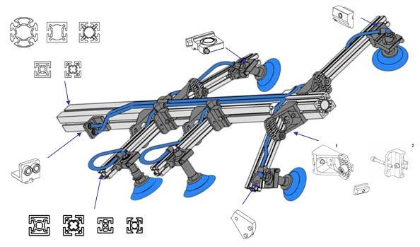
4 AMG GRIPPERS FOR ROBOTS The A.M.G. gripper is a modular manipulation device composed of standard components assembled together by tightening screws. Our robot grippers consist of a central profile in aluminium, generally called the main boom, to which other profiles, called antennae or secondary boom, are fixed. Along the secondary boom, various support structures are used to hold the suction cups. This manual is designed to allow you to build or repair your own grippers by yourself without any difficulty or damage. Presented in the form of information sheets, they contain all the preparation and assembly instructions you will need. 4 / 27
5 PREPARATION OF THE PARTS 5 / 27

6 PREPARING A MAIN BOOM ON A PROFILE 50 X 50 mm (PRS and PRS ) Part 1 of 2 PRS PRS I / Preparation of a main boom compatible with a G1 type interface - Check that the profile has the needed length - Insert the template GPB 01 0G1 in one of the grooves until it is stopped up against the profile Template GPB 01 0G1 or GPB 01 0G2 PRS or PRS Block the template in position by turning the handle - Drill a hole ø 5 6 / 27
7 PREPARING A MAIN BOOM ON A PROFILE 50 X 50 mm (PRS and PRS ) Part 2 of 2 - Slide the positioning insert ref. BAP 01 0G1 into the groove and bolt it down in position using two grub screws Hc M5 x 12 and a split pin diameter 5 x 40. split pin ø5x40 BAP 01 0G1 2 Grub Screws Hc M5x12 II / Preparation of a main boom compatible with a G2 type interface The process is identical to the first one. Only the drilling template is different: use template P/N GPB 01 0G2. 7 / 27

8 PREPARING A MAIN BOOM ON A PROFILE 40 X 40 mm (PRS and PRS ) Part 1 of 2 PRS PRS I / Preparation of a main boom compatible with a G3 type interface - Check that the profile has the needed length - Insert the template GPB 01 0G1 in one of the grooves until it is stopped up against the profile Template GPB 01 0G3 PRS or PRS Block the template in position by turning the handle - Drill a hole ø 5 8 / 27
9 PREPARING A MAIN BOOM ON A PROFILE 40 X 40 mm (PRS and PRS ) Part 2 of 2 - Slide the positioning insert ref. BAP 01 0G3 into the groove and bolt it down in position using two screws Hc M5 x 10 and a split pin diameter 5 x 30. BAP 01 0G3 Split pin ø5x30 2 Grub Screws Hc M5x10 9 / 27
 or of diameter 75 mm (PRS 11 075).")
 for length more than 800 mm.")
10 PREPARING A SECONDARY BOOM SECONDARY BOOM 30 X 30 mm OR 40 X40 mm WITH BRACKETS SERIES 50 Part 1 of 2 Principle The brackets series 50 allow fixing a secondary boom on a main boom of 50 x 50 mm (PRS and PRS ) or of diameter 75 mm (PRS ). In order to choose the dimension of the secondary boom, you can follow the following principle: - Profile 30 x 30 (PRS ) for length up to 400 or 500 mm - Profile 30 x 30 (PRS ) for length between 400/500 mm and 800 mm - Profile 40 x 40 (PRS or PRS ) for length more than 800 mm. Preparation of the profile - Check that the profile has the needed length - Insert the drilling template GPA in one of the 8 mm grooves until it is stopped up against the front surface of the section Template GPA PRS , PRS , PRS Or PRS Block the template in position by turning the handle A - A - Drill a hole ø / 27
11 PREPARING A SECONDARY BOOM SECONDARY BOOM 30 X 30 mm OR 40 X40 mm WITH BRACKETS SERIES 50 Part 2 of 2 Assembly - Slide the T-plate PLA 311M6 of the bracket with notches in the groove of the profile - Link the two brackets together using a screw CHc M6 x 55. This must pass through the hole diameter 6.1 mm of the secondary boom. Note : the tightening torque for each screw is 15 N.m Bracket EQU 01 3M6 Screw CHc M Washer dia 6 RON Profile already drilled T-plate PLA 31 1M6 T-plate PLA 41 1M6 Bracket EQU Screw CHc M Washer dia 6 RON Blocker BLR Circlip int. dia 12 Screw CHc M Washer dia 6 RON Screw CHc M Washer dia 6 RON linking the 2 brackets and passing through the hole dia 6.1mm of the profile 11 / 27
12 PREPARING A SECONDARY BOOM SECONDARY BOOM 30 X 30 mm OR 40 X40 mm WITH BRACKETS SERIES 30 AND 40 Part 1 of 2 Principle The brackets series 40 allow fixing a secondary boom on a main boom of 40 x 40 mm (PRS and PRS ). Preparation and assembly of the section Identical to series 50. Bracket EQU 01 3M6 Screw CHc M Washer dia 6 RON Profile already drilled T-plate PLA 31 1M6 T-plate PLA 41 1M6 Bracket EQU Screw CHc M Washer dia 6 RON Blocker BLR Circlip int. dia 12 Screw CHc M Washer dia 6 RON Screw CHc M Washer dia 6 RON linking the 2 brackets and passing through the hole dia 6.1mm of the profile 12 / 27
13 ASSEMBLY OF A GRIPPER 13 / 27


14 ATTACHING THE SECONDARY BOOM ON A MAIN BOOM 50 X 50 mm OR DIAMETER 75 mm Principle The secondary boom Series 50 are the only ones which can be used on a main boom of 50 x 50 mm or diameter 75 mm. Once placed along the main boom, the secondary boom can be tilted from the horizontal axis according to predefined angles. Maintaining the secondary boom at the desired inclination is achieved by a system using a notching technique. This system has been patented by A.M.G. Secondary boom with main boom of 50 x 50 mm Secondary boom with main boom of dia 75 mm Assembly - Place the secondary boom at the end of the main boom then slide it along while introducing the two T-plates PLA 41 1M6 in the 8 mm groove of the profile (1) - When the secondary boom is in the desired position, tighten the two clamping screws (2). The required tightening torque for each screw is 15 N.m. Caution: If the gripper has several secondary booms, first attach those closest to the starting point (on the same side as the positioning insert). 2 1 Slide the 2 T-plates PLA 41 1M6 into the groove of the main boom Main boom Tighten the 2 clamping screws 14 / 27
15 ATTACHING THE SECONDARY BOOM Adjusting the inclination It is possible to tilt the secondary boom from the horizontal axis according to pre-defined angles: 7, 14, 21 and 28 (3). To do this, simply loosen the blocker, tilt the secondary boom at the desired notch and retighten the locking screw. Two additional inclinations (34 and 40 ) are possible. For this, place the clamping screw in position 2 and the blocker in one of the two lower grooves (4). The tightening torque for each screw is 15 N.m. 3 Basic angular adjustment (7, 14, 21 and 28 ) Screw on position 1 Blocker Additional angular adjustment (34 and 40 ) 4 Screw on position 2 Blocker 15 / 27
16 ATTACHING THE SECONDARY BOOM ON BOOM 40 X 40 mm OR 30 X 30 mm Principle Secondary boom Series 40 are the only ones which can be used on a main boom 40 x 40 mm. The principle is identical to the Series 50. Assembly Identical to the main boom 50 x 50. Adjustment of inclination It is possible to tilt the secondary boom from the horizontal axis according to pre-defined angles: 7 and 14 (3). To do this, simply loosen the blocker, tilt the secondary boom at the desired notch and retighten the locking screw. Two additional inclinations (20.5 and 26.5 ) are possible. For this, place the clamping screw in position 2 and the blocker in one of the two lower grooves (4). The tightening torque for each screw is 15 N.m. 3 Basic angular adjustment (7 and 14 ) Screw on position 1 Blocker Screw on position 2 Blocker 4 Additional angular adjustment (20.5 and 26.5 ) 16 / 27
17 USING THE BALL JOINT HOLDER There are three types of ball joint holders: - Ball joint holders for tube - Spring loaded ball joint holders - Anti rotation spring loaded ball joint holders. Assembly of a ball joint holder for tube - Slide the split ball joint ROT into the ball joint holder SPR then turn through a quarter of a turn - Place screw CHc M6 X 55 in its housing and tighten slightly in the plate PLA 41 1M6 - Insert the selected tube in the ball joint then tighten the screw to maintain in position. 1 Assembly of ball joint holder for tube Tube Ball ROT T-plate PLA 41 1M6 Ball joint holder with tube Holder SPR Screw CHc M6 x 55 (Class 12.6) Washer dia 6 RON / 27
18 USING THE BALL JOINT HOLDER Assembly of a spring loaded ball joint holder - Slide the split ball joint ROT into the ball joint holder SPR then turn through a quarter of a turn - Turn over the ball joint holder then insert the ring BAC with ring BAG in the ball joint. Maintain in position using a circlip external diameter 20 - Insert the spring along the tube and slide the whole in the ring BAC Attach the tube by tightening the connector RAC 01 M15 - Place the screw CHc M6x55 in its hole and tighten in the T-plate PLA 41 1M6. 2 Assembly of spring loaded ball joint holder Ball ROT Groove at this side Ring BAC BAG RAC 01 M15 T-plate PLA 41 1M8 Turn ball joint holder Washer dia 6 RON Screw CHc M6 x 55 (Class 12.6) Holder SPR Circlip ext dia 20 Tube (AXE 02 ) and spring (ref according to the length) Spring loaded ball joint holder assembled 18 / 27
19 USING THE BALL JOINT HOLDER Assembly of an anti rotation spring ball joint holder - Slide the split ball joint ROT in the ball joint holder SPR as indicated in view 3. Place the half moon DML inside the ball joint engaged in the split pin, then insert the pin with the spring by tightening the connector RAC 01M15 in the upper section. 3 Assembly of anti rotation spring loaded ball joint holder Ball ROT Turn ball joint holder Holder SPR Circlip ext dia 20 Screw CHc M6 x 55 (Class 12.6) Placing the pin with the ball ROT and the insert DML Anti rotation spring loaded ball joint holder assembled Place the insert DML Tube AXE / 27
20 USING THE BALL JOINT HOLDER ATTACHING THE BALL JOINT HOLDER TO A PROFILE For all the types of ball joint holders, the method of attaching it on the profile is the same: - Slightly loosen the T-plate PLA 41 1M6 - Slide the T-plate PLA 41M6 of the ball joint holder into one of the grooves in the profile then tighten in the desired position. The recommended tightening torque is 15 N.m T-plate PLA 41 1M6 20 / 27
 by 20 the angular adjustment of a ball joint holder from the horizontal axis. (Picture 1) - The vertical angled wedge ref.")
21 USING THE ANGLED WEDGES There are two types of wedges: - The horizontal angled wedge ref. PA CPH allows increasing (or decreasing) by 20 the angular adjustment of a ball joint holder from the horizontal axis. (Picture 1) - The vertical angled wedge ref. PA CPV allows increasing (or decreasing) by 35 the angular adjustment of a ball joint holder from the vertical axis. (Picture 2) 1 2 Use of the horizontal angled wedge Note : this wedge can be used with any type of ball joint holder Several assembly solutions are possible - Insert the angled wedge between a ball joint holder and a T-plate PLA 41 1M6. Link the entire assembly using a screw CHC M6 X 65 - Slide the assembly by inserting the T-plate PLA 41 1M6 in one of the grooves - Once the desired position has been achieved, tighten the screw taking care to ensure the split pins of the wedge are correctly positioned in the rear groove of the ball joint holder. The recommended screw tightening torque is 15N.m. Profile Washer dia 6 RON Screw CHc M6 x 65 Angled wedge T-plate PLA 41 1M6 Split pins Profile Ball joint holder Angled wedge 21 / 27
22 USING THE ANGLED WEDGES Use of the vertical angled wedge Note: this wedge can only be used with the ball joint holder for tube - Slide the wedge by inserting the T-plate PLA 41 1M6 in one of the grooves then tighten the screw - Then screw the ball joint holder on the wedge ensuring the heel of the wedge is correctly positioned in the groove of the ball joint holder. The recommended tightening torque for the screw is 15N.m. Profile Washer dia 6 RON Screw CHc M6 x 20 T-plate PLA 41 1M6 Angled wedge Ball joint holder Washer dia 6 RON Screw CHc M6 x 55 Example with PA CPV Example with PA CPH / 27
23 USING THE PNEUMATIC BRACKET These brackets allow the quick pneumatic connection of a gripper. X Caution: the distance between the bracket and the end of the main boom depends on the type of the needed gripper (G1, G2 or G3). Attaching the bracket PA ESR on the main boom - The bracket is equipped with one or two RFS connectors and the T-pale PLA 41 1M6 - Slide the bracket in the groove opposite to the one housing the positioning insert. - Then tighten the screw Interface Gripper 23 / 27

24 USING THE INTERFACE Caution: it is very important to ensure that the gripper is well positioned in the interface. 1 Put the gripper in the interface 2 Make sure that the pneumatic connection is done 3 Finally, activate manually the lever Good pneumatic connection and clamping of the gripper 24 / 27
25 PNEUMATIC CABLING OF A GRIPPER Pneumatic cabling of a gripper consists in linking the suction cups (attached at the extremities of the secondary boom) to the pneumatic connection bracket (attached at the extremity of the main boom). Once equipped with the pneumatic equipment, the gripper can be inserted in the interface. The pneumatic connection between gripper and interface is made automatically, so it is possible to either suck or blow air. Cabling is made using quick connectors. This allows the easy and rapid assembly of the gripper. Exceptionally and on request, cabling can be made using screw-equipped coonectors Standard pneumatic cabling incorporates the following steps : - Screwing of connectors on the tube at the ball joint holders (angled or straight connectors depending on the inclination and the connection with the hose) - Linking of these connectors together using Y connectors and hoses of diameter 8mm. It is better to use the Y connectors but T or crossed connectors can also be used - Linking the end of the hose to the pneumatic connection bracket at the extremity of the main boom. A few recommendations - Use only calibrated hoses - Never bend a hose. The minimum curve radius must be 55 mm - If a hose is marked by folding, replace it Caution : Attaching the hoses to the connectors (independently of their type : straight, angeld, ) must be as follows : the end of the hose must be cut straight and cleanly.. 25 / 27


26 PNEUMATIC CABLING OF A GRIPPER 26 / 27


27 AMG Industries Zone Artisanale - BP GROSSOEUVRE France STANDARD : +33 (0) Fax : +33 (0) accueil@amg-sa.com 27 / 27
aluminium profile system
 aluminium profile system 63 AME System aluminium profiles overview series profiles introduction 80x80 x80 x80/180 x Aluminium profiles are provided with longitudinal grooves which can be used in conjunction
Operating Manual. for CUTTING, PERFORATING, BENDING SLB120
 Operating Manual for CUTTING, PERFORATING, BENDING SLB120 31040\B06eng 0896 0 Contents 1. Scope of delivery... 1 2. Technical specifications... 1 3. Applications... 1 4. Commissioning... 2 5. Cutting...
INSTALLATION INSTRUCTIONS VENETIAN 84" SLIDING SHOWER DOOR SYSTEM (180º INSTALLATION)
") INSTALLATION INSTRUCTIONS VENETIAN 84" SLIDING SHOWER DO SYSTEM (180º INSTALLATION) 28539 Industry Drive, Valencia, CA 91355 Toll Free Phone: (877) 728-3874 Toll Free Fax: (888) 440-9567 Phone: (661) 775-1675
INSTALLATION INSTRUCTIONS VENETIAN 84" SLIDING SHOWER DO SYSTEM (180º INSTALLATION) 28539 Industry Drive, Valencia, CA 91355 Toll Free Phone: (877) 728-3874 Toll Free Fax: (888) 440-9567 Phone: (661) 775-1675
Clamping devices 521
 Clamping devices 521 522 Product overview Clamping devices Adjustable straps K0001 Hook clamps K0012 Goose-neck straps with long slot K0002 Page 526 Hook Clamps with collar K0013 Page 535 Equipped clamps
Easy Step by Step Manual
 Easy Step by Step Manual Teletower Mini XL Wall-Floor installation The tower packages #1-#2-#3 Open Base Package #1 for the main tower parts. Here you see the three tower tubes (H-Head, M-Middle, F-Feed)
Model No: TC10. Parts Information: Tyre Changer - Automatic
 Page 1 of 11 1 TC10.01 BODY 2 TC10.02 COLUMN 3 TC10.03 HORIZONTAL ARM ASS'Y 4 TC10.04 WASHER 5 TC10.05 RUBBER FOOT 6 TC10.06 COVER 7 TC10.07 SCREW M14x42 8 TC10.08 PRESS COVER 9 TC10.09 STOP-UP 10 TC10.10
Operating instructions. Fine boring head Ø3-88 with digital display
 Operating instructions Fine boring head Ø3-88 with digital display English 1. Basic safety information Before first use, please read the operating instructions carefully. These provide important safety
SLW 6 Channel Letter Brake. User Guide. Operation and Mounting Instructions
 SLW 6 Channel Letter Brake User Guide Operation and Mounting Instructions Scope This document describes the operation and mounting instructions for the SLW 6" Channel Letter Brake. Please read all instructions
Operating instructions. Twin cutter boring head Ø mm
 Operating instructions Twin cutter boring head Ø23.5-153.0 mm English 1. Basic safety information Before first use, please read the operating instructions carefully. These provide important safety information
SUMMARY. V-Lock SYSTEM BASIC ELEMENTS ACTUATORS. P V-Lock GENERAL INTRODUCTION 2. P V-Lock FIXING ELEMENTS 10 SUMMARY. P V-Lock ADAPTORS 17
 SUMMARY A3 V-Lock SYSTEM P V-Lock GENERAL INTRODUCTION 2 BASIC ELEMENTS P V-Lock FIXING ELEMENTS 10 P V-Lock ADAPTORS 17 SUMMARY P PROFILES 28 P V-Lock ACCESSORIES AND SPARE PARTS 32 1 A3 GENERAL INTRODUCTION
Brochure Includes: Set-up Instructions Operating Instructions Parts List Fundamentals of Drill Sharpening. Patent 3,952,459
 Patent 3,952,459 Brochure Includes: Set-up Instructions Operating Instructions Parts List Fundamentals of Drill Sharpening Accurately Sharpens most drills bits. Now, with this one low-cost, simple machine,
Hollywood Swing Away 2 and 4 Bike Racks Assembly and Installation Guide
 Hollywood Swing Away 2 and 4 Bike Racks Assembly and Installation Guide Tools Required: two adjustable wrenches, pliers, ¾ socket wrench recommended Note: please do assembly near your vehicle as you Can
Mounting a BalanceBox 400 to a brick wall
 Unpack the BalanceBox 400 and remove the Wall frame cover and its bag of screws. Slide the cover out at the top. NOTE: the cover is NOT included with the BalanceBox 400H LOCK SCREW HOLE MOBILE STAND MOUNTING
These Installation Instructions are valid for antennas in the following version:
 Installation Instructions 4 ft CompactLine Antennas (with E-Mount 200 km/h) SB, SBX NMT 480-12(e) These installation instructions have been written for qualified, skilled personnel. The antenna shall be
FABA. Installation Instructions. Conductor Bar System. Publication #FABA-03 3/1/04 Part Number: Copyright 2004 Electromotive Systems
 FABA Conductor Bar System Installation Instructions Publication #FABA-03 3/1/04 Part Number: 005-1062 Copyright 2004 Electromotive Systems 1S 100 Z Installation Instructions Contents: Basic Diagram - -
ROBOT KR 350. Installation, Connection, Exchange. Ro/Me/03/ en. 1of 26
 ROBOT KR 350 Installation, Connection, Exchange 1of 26 e Copyright KUKA Roboter GmbH This documentation or excerpts therefrom may not be reproduced or disclosed to third parties without the express permission
50, ,000 18,800 8,000. CODE 04 ER (ER ) UPC Chuck/W ITS Central Chuck. CODE 04 ER (ER ) UPC Pallet For Alignment
 UPC Chuck/W ITS Central Chuck. CODE 04 ER (ER ) UPC Pallet For Alignment") CODE 04 ER-007826 (ER-017777) UPC Pallet For Alignment CODE 04 ER-007823 (ER-016092) UPC Chuck/W ITS Central Chuck Application To align angular position and to determine the center of UPC chucks. Please
CODE 04 ER-007826 (ER-017777) UPC Pallet For Alignment CODE 04 ER-007823 (ER-016092) UPC Chuck/W ITS Central Chuck Application To align angular position and to determine the center of UPC chucks. Please
SINCE 1922 P UBLICATION N O
 SINCE 1922 GARED SPORTS MICRO-Z SET-UP INSTRUCTIONS VERY IMPORTANT! READ INSTRUCTIONS CAREFULLY AND FOLLOW STEP BY STEP SET-UP PROCEDURE P UBLICATION N O. 5 5 1 7 5 2 9 1 6 Recommended tools and accessories.
SB-WM-ART2-L-BL SB-WM-ART2-XL-BL
 SB-WM-ART2-L-BL SB-WM-ART2-XL-BL Weatherproof Universal Dual-Arm Articulating Mount for Large TVs INSTALLATION MANUAL WARNING The maximum weight of this wall mount is 150 lbs (68.04 kg). Use with heavier
3.2.3 Rear Door Window and Quarter Window Carrier Assembly
 Tighten all bolts. Tighten bolts marked -1- and -2- in specified sequence. Tightening torque: 8 Nm Remaining bolts can be tightened in any sequence. Insert door window -3- through window recess without
Clamping bolts Eccentrical cams clamping units
 2.3 Shaft Clamping bolts Eccentrical cams clamping units 2.9 2.8 2.7 2.6 2.5 2.4 2.3 2.2 2.1 2.3 Clamping bolts, Eccentrical cams, Shaft clamping units Page 641 2.3 Clamping bolts, Eccentrical cams, Shaft
Installing The Aliens Extermination Deluxe 50" Cabinet with Sintra Marquee
 Installing The Aliens Extermination Deluxe 50" Cabinet with Sintra Marquee Document Part #: 040-0262-01 This document describes how to install The Aliens Extermination Deluxe Cabinet with Sintra Marquee
.00025" PER CLICK. As you turn the adjustment screw you should be able to feel a click. Each click will change the part diameter.00025".
 ULTRA PRECISION DIAMETER ADJUSTMENT.00025" PER CLICK The ultra precision diameter adjustment is extremely accurate, as well as, quick and easy to use. The adjustment mechanism is spring loaded to take
Adjusting 45 Compass Hardware Including 4-Point
 Adjusting 45 Compass Hardware Including 4-Point Compass Hardware - US Patent No. 7,104,610 & 7,891,739 Apparatus for Mounting a Wheelchair Back Quick Release Fixed 4-Point The information in this manual
Hardware and Components:
 Hardware and Components: (A) 4X 5/16 x 1 Carriage Bolt (B) 2X 5/16 x 2-1/4 Carriage Bolt (C) 2X 5/16 x 3-1/4 Hex Bolt (D) 2X 5/16 x 3/4 Hex Bolt (E) 2X 5/16 x 1-1/4 Hex Bolt (F) 5/16 x 2-1/4 Hex Bolt (G)
7878 K940. Checkpoint Antenna. Kit Instructions. Issue B
 7878 K940 Checkpoint Antenna Kit Instructions Issue B Revision Record Issue Date Remarks A July 7, 2009 First issue B Nov2013 Revised the Checkpoint installation procedures for 7878 and 7874 scanners Added
SB-WM-ART1-M-BL. Weatherproof Universal Single-Arm Articulating Mount for Medium Displays INSTALLATION MANUAL
 SB-WM-ART1-M-BL Weatherproof Universal Single-Arm Articulating Mount for Medium Displays INSTALLATION MANUAL WARNING The maximum weight of this wall mount is 90 lbs (41 kg). Use with heavier than the maximum
Assembly Instructions for Model: VMDD26
 Assembly Instructions for Model: VM26 Thank you for choosing a Sanus Systems Vision Mount wall mount. The VM26 is designed to mount up to 63 lat panel televisions weighing up to 175 lb. to a vertical wall.
Modular transfer system. PDF- Catalog Modular Transfer System
 Modular transfer system PDF- Catalog Modular Transfer System 1 Modular Transfer System TLM 1000 156, route de Lyon 38300 DOMARIN FRANCE Phone (33) 4 37 03 33 55 Fax (33) 4 37 03 33 59 September 2001 edition
INSTALLATION INSTRUCTIONS HEAVY DUTY TILT WALL MOUNT Model: PPH-2000
 INSTALLATION INSTRUCTIONS HEAVY DUTY TILT WALL MOUNT Model: PPH-2000 Specifications: Accomodates Akira and Orion 84" displays without interface bracket; accomodates other large flat panel displays with
Repair manual. Fifth-wheel coupling JSK 38/50
 Repair manual Fifth-wheel coupling JSK 38/5 ZDE 199 3 12 E 6/212 1 Foreword Table of contents Page Fifth wheel couplings are connecting parts that must comply with very high safety requirements and must
BX1956 Installation Instructions Chrysler PT Cruiser (Include Turbo)
") BX1956 Installation Instructions 2001-04 Chrysler PT Cruiser (Include Turbo) Serial No. The front fascia and metal bumper are removed for baseplate installation. Factory metal bumper will not be reinstalled.
BX1956 Installation Instructions 2001-04 Chrysler PT Cruiser (Include Turbo) Serial No. The front fascia and metal bumper are removed for baseplate installation. Factory metal bumper will not be reinstalled.
PFD-22 Top OHC Patch Fitting & PFD-10 Bottom Patch Fitting Installation Instructions
 Top OHC Patch Fitting & Bottom Patch Fitting Installation Instructions For Installation Assistance, Call 855.594.6989 www.assaabloyglass.us Tools Needed: Torque Wrench and Bit 5mm Allen Wrench 6 7 /16"
Section 11 CABLE & ROD SYSTEMS, SIGN FIXING & SIGN STANDOFFS. Web. acrylicdesign.ie .
 Section 11 CABLE & ROD SYSTEMS, SIGN FIXING & SIGN STANDOFFS Web. acrylicdesign.ie Email. sales@acrylicdesign.ie Acrylic Design 2004-2015 Mobile Cable System Components Single panel clamp Stand Off for
User Instructions Multiline Otter Scoreboard Caddy Assembly
 List of parts: User Instructions Multiline Otter Scoreboard Caddy Assembly Single Caddy Double Caddy 1 1 Base assembly with attached wheels 2 4 1 1 2 4 4 8 10 20 12 Uprights (60 or 74 aluminum extrusion)
INSTALLATION INSTRUCTION RRU DOUBLE LIGHT POLE MOUNT
 INSTALLATION INSTRUCTION RRU Double Light Pole Mount for installation of two RRU units on mast, towers or other vertical structures. CUE DEE YOUR INNOVATIVE PARTNER 1 CONTENTS 1. PRODUCT COVERED IN THIS
LocoGear. Technical Bulletin - 14 November 28, 2003 Copyright 2003 by LocoGear LIVE STEAM CASTINGS. Tech Bulletin - 14
 LIVE STEAM CASTINGS LocoGear Tech Bulletin - 14 John D.L. Johnson 3879 Woods Walk Blvd Lake Worth, FL 33467-2359 jjohnson@locogear.com www.locogear.com Technical Bulletin - 14 November 28, 2003 Copyright
Adjusting 90 Compass Hardware Including 4-Point
 Toll Free 800.564.948 www.comfortcompany.com 509 South nd Ave Bozeman, MT 59718 Adjusting 90 Compass Hardware Including 4-Point Compass Hardware - US Patent No. 7,104,610 & 7,891,739 Apparatus for Mounting
Single Band 125mm Profile Panel Antennas Installation and Operation Instructions Including APM-F-084-S4 & APM-T-085-S4 Mounting Kits
 General Single Band 125mm Profile Panel Antennas Installation and Operation Instructions Including APM-F-084-S4 & APM-T-085-S4 Mounting Kits This instruction sheet contains all necessary information required
BX2173 Installation Instructions Ford Focus (including the 2.3L engine) 2003 Ford Focus SVT
 2003 Ford Focus SVT") BX2173 Installation Instructions 2000-04 Ford Focus (including the 2.3L engine) 2003 Ford Focus SVT Serial No. The front fascia, coolant line bracket and anti-pollution devices are removed for baseplate
BX2173 Installation Instructions 2000-04 Ford Focus (including the 2.3L engine) 2003 Ford Focus SVT Serial No. The front fascia, coolant line bracket and anti-pollution devices are removed for baseplate
ORTOP Modular Robot v3.0 Arm Assembly
 Base Plate Assembly Parts Needed: Arm Assembly BAG 1 2 Socket Head Cap Screw, 1-1/4" 2 Socket Head Cap Screw, 1/2" 2 Button Head Cap Screw, 3/8" 6 Nuts 1 Gear Hub Spacer 1 Flat Building Plate 1 Single
MOUNTING INSTRUCTIONS
 Standard Mounting Bracket Tilting Bracket* Mounting example Right side for upper tilt from 0 to 20 20 Spare parts: p/n SA197 Materials: extruded aluminum Hardware: stainless & zinc plated steel Dimensions
PACKING LIST MACO V-5000
 PACKING LIST MACO V-5000 PART QTY O.D. SIZE LENGTH DESCRIPTION CHECKLIST T47P 4 5/8.050 36 Aluminum Tubing _ T43P 1 7/8.050 48 Aluminum Tubing _ T18P 1 3/4.050 48 Aluminum Tubing _ T15P 1 5/8.050 48 Aluminum
STRAIGHT HANDLEBAR KIT
 STRAIGHT HANDLEBAR KIT P/N 2881973 APPLICATION All straight bar applications, excluding 550 Indy and Voyageur models BEFORE YOU BEGIN Read these instructions and check to be sure all parts and tools are
Profiform 200 Profiform 320. Operating manual
 Profiform 200 Profiform 320 Operating manual Profiform 200 / Profiform 320 Operating manual Page 1 Table of contents 1. General information Page 2 2. Profile of the Profiform sheet metal working machines
Series B Medical Gas Service Outlet Upgrade Kits
 Installation Instructions Series B Medical Gas Service Outlet Upgrade Kits For additional information concerning operation of Puritan Bennett Series B Quick-Connect Outlet Valves, refer to Operating Instructions
PURESTREAM SYSTEM - ASSEMBLY GUIDE
 PURESTREAM SYSTEM - ASSEMBLY GUIDE VISIT OUR WEBSITE : www.cagpurification.com our installment procedure videos in the PURESTREAM Piping section. NECESSARY TOOLS FOR INSTALLATION We suggest the use of
ROTARY TABLE OPERATION AND SERVICE MANUAL HORIZONTAL AND VERTICAL. Horizontal & Vertical. Rotary Table (HVRT) Tilting Rotary Table
 Tilting Rotary Table") Horizontal & Vertical Rotary Table (HVRT) OPERATION AND SERVICE MANUAL Tilting Rotary Table Horizontal & Vertical Rapid Indexer VERTICAL AND HORIZONTAL ROTARY TABLE This Horizontal & vertical table is
Horizontal & Vertical Rotary Table (HVRT) OPERATION AND SERVICE MANUAL Tilting Rotary Table Horizontal & Vertical Rapid Indexer VERTICAL AND HORIZONTAL ROTARY TABLE This Horizontal & vertical table is
ATTACH WALL PLATE TO WALL
 DANGER! The Elite ar m contains high p r e s s u r e g a s s p r i n g s. T h e following cautions MUST be observed to avoid serious injury. 1. Do not attempt to adjust your Elite arm until everything
Band-Master ATS Nano Pneumatic Banding Tool Operating Instructions
 Band-Master ATS 601-118 Nano Pneumatic Banding Tool CONTENTS 601-118 Overview... 3 Safety.... 5 Initial Tool Set-up... 5 Regulator assembly mounting... 5 Attach tool head to regulator.... 6 Operating instructions...
Fig. 2 DORMA-Glas Stand/Issue 02/03 Seite/Page 1/7
 FSW Installation instructions Track rail 75 x 72 mm 1. Ceiling substructure and installation of the track rail (Fig. 1): The track rail must be bolted over its entire length (including the stacking track
PROPELLER SHAFT PR 3 COMPONENTS
 PR3 COMPONENTS PR4 REMOVAL OF 1. DISCONNECT FRONT (a) Place the matchmarks on the both flanges. (b) Remove the four bolts, washers and nuts. (c) Pull the yoke from the transfer. (d) Insert SST in the transfer
Dublin Stalls Installation Instructions
 Dublin Stalls Installation Instructions RAMM Horse Fencing and Stalls 13150 Airport Hwy. Swanton, OH 43558-9615 1-800-434-8456 Rev. 9/13/17 Part Identification Round Track Bracket (4) (Not Painted) Round
Fifth-wheel coupling JSK 38/50
 Repair manual Fifth-wheel coupling JSK 38/5 ZDE 199 3 12 E 6/25 1 LT SK38C-3 English RevA Foreword Table of contents Page Fifth wheel couplings are connecting parts that must comply with very high safety
Adjustable Feet Castors Accessories for Floor Elements
 Adjustable Feet Castors Accessories for Floor Elements Products in this section Levelling Knuckle Feet Threaded spindles for infinite height adjustment Metal or plastic foot plate Knuckle Feet X Compatible
HANDLEBAR KIT P/N APPLICATION BEFORE YOU BEGIN KIT CONTENTS TOOLS REQUIRED. Instr Rev Page 1 of 6
 HANDLEBAR KIT P/N 2881993 APPLICATION All straight bar applications, excluding 550 Indy and Voyageur models BEFORE YOU BEGIN Read these instructions and check to be sure all parts and tools are accounted
INSTALLATION INSTRUCTIONS FOR INSTALLING T-SERIES EXTRA HEAVY DUTY LEVER LOCKSET
 HIGH EDGE 2 1/4"(57mm) 03079400070 INSTALLATION INSTRUCTIONS FOR INSTALLING T-SERIES EXTRA HEAVY DUTY LEVER LOCKSET IMPORTANT: THIS LOCK IS NON-HANDED. LOCK IS FACTORY PACKED PREADJUSTED FOR 1³ ₄" (45mm)
Repair Manual MWS45A-MWS50A-MWS55A MW32A-MWS36A-MWS40A. Ref Rev.D General Pump is a member of the Interpump Group
 MW/S 8 Repair Manual MWS45A-MWS50A-MWS55A MW32A-MWS36A-MWS40A General Pump is a member of the Interpump Group INDEX 1. INTRODUCTION..................................................Page 3 2. REPAIR INSTRUCTIONS...........................................Page
Diesel Pile Hammer D30-32 Part # 66508
 Diesel Pile Hammer D30-32 Part # 66508 2 Diesel Pile Hammer D30-32 Part # 66508 Pos Order No Pg Description Qty 66508 Diesel Pile Hammer D30-32 cmpl 1 1 108742 4 Cylinder Lower Part cmpl 1 2 60151 Inner
Installation Manual Integration
 Integration and mechanical adjustment for diameter gauge www.detector-france.com A - PRESENTATION OF DIAMETER GAUGE 2 A-1 - Rrobes F00 and F00L 2 A-2 - Internal Sensor with radial ouput 3 B - ADJUSTMENT
Tools Required. * When installing on a fire door, please see instructions below. *
 CL615 Tubular Mortice Latch with Code Free option CL615 Tubular Mortice Latch with Code Free option Number relating to picture Item 1 Front Plate and handle * 2 Back Plate and handle * 3 Neoprene seals
Zero Point Clamping System. ZERO lock BALL lock
 Zero Point Clamping System ZERO lock BALL lock kap3 kap 263 Technical information regarding ZERO lock Zero Point Clamping System Application The modularly designed, flexible ZERO lock Zero-Point Clamping
1 of 2 3/3/2017 4:49 PM
 1 of 2 3/3/2017 4:49 PM Front Door Window, Assembly Overview 1 - Window guide - Inserted on flange 2 - Door 3 - Inner window recess seal - Inserted on flange 4 - Bolt - 20 Nm 5 - Carrier assembly - Window
HBS-AP ASSEMBLING INSTRUCTIONS
 ALUMINIUM PIPEWORK - ALUMINIUM PIPEWORK - ALUMINIUM PIPEWORK 97 HBS-AP ASSEMBLING INSTRUCTIONS 1. INTRODUCTION 1.1. This manual is very easy to consult and we recommend reading it before starting work,
M2 Antenna Systems, Inc. Model No: 20M5LD
 M2 Antenna Systems, Inc. Model No: 20M5LD SPECIFICATIONS: Model... 20M5LD Frequency Range... 14.0 14.350 MHz *Gain (Full Band)... 10.2 dbi Typical Front to back... 23 db Typical Beamwidth... E=50 / H=66
TECHNICAL INFORMATION
 TECHNICAL INFORMATION P 1 / 11 Model No. Description CONCEPT AND MAIN APPLICATIONS Specification Standard equipment TCT saw blade... 1 Rear table set (exclusively Europe, Turkey, South Africa..1 2704 This
Thank you for purchasing out product! *Please read these instructions and follow them step by step. *
 Page 1 of 7 AD17 AA DS 4 X 16 T12 Thank you for purchasing out product! *Please read these instructions and follow them step by step. * STEP 1. Slide two support posts (REF. # 24) into the two outside
WARNING. BX Saturn SC Saturn SC Saturn SL, SL Saturn SL2, SW Saturn SW1 Installation Instructions
 Please read BOTH these Installation Instructions and the General Instructions before attempting to install or operate this equipment. 1. Blue Ox towing products and accessories are intended to be installed
Assembly instructions
 Commission: Order no.: Rondo Pavilion PR Ø3.9 Technical changes reserved Assembly instructions As at: 05.011 Sliding door Dear Garden lover, we congratulate you on the purchase of a quality product from
INSTALLATION TORSION SPRING FRONT OR REAR MOUNT LOW HEADROOM. 1 Cutting Vertical Track. 2 Fully Adjustable Jamb Brackets
 TORSION SPRING FRONT OR REAR MOUNT LOW HEADROOM Wayne Dalton, a division of Overhead Door Corporation P.O. Box 67, Mt. Hope, OH., 44660 Supplemental insert Copyright 2015 Wayne Dalton, a division of Part
PORTA-DOCK, INC. AP17 APD DS 4 X 16 T12 AW17 CPD DS 4 X 16 T12
 Page 1 of 7 PORTA-DOCK, INC. AP17 APD DS 4 X 16 T12 AW17 CPD DS 4 X 16 T12 *For Beige Decking Add the Letter B to Model* Thank you for purchasing out product! *Please read these instructions and follow
Ball Rail Tables Maintenance Manual
 Industrial Hydraulics Electric Drives and Controls Linear Motion and Assembly Technologies Pneumatics Service Automation Mobile Hydraulics Ball Rail Tables Maintenance Manual The Drive and Control Company
Diesel Hammer Model D19-42 Part #
 Diesel Hammer Model D19-42 Part # 120491 2 Diesel Pile Hammer Part # 120941 Pos Order No. Pg Description Qty 120941 Diesel Pile Hammer D19-42 (Bauer MNR:426514) 1 160198 4 Cylinder Lower Part cmpl 1 2
INSTALLATION INSTRUCTIONS
 INSTALLATION INSTRUCTIONS ANSI/BHMA - A156.2 BOX CONTENTS CHECK THAT THE CONTENTS OF YOUR BOX ARE CORRECT ACCORDING TO THE MODEL Model 600/605 Model 610/615 Model 620/625 1 Front plate and handle 2 Back
Instruction Sheet RADIO FREQUENCY SYSTEMS. Install. Instr. for Microwave Parabolic Antennas 2.4 m (8 ft) No Rev.
 No Rev.") Instruction Sheet No. 412764 Rev. B ECO 12469 Install. Instr. for Microwave Parabolic Antennas 2.4 m (8 ft) These Installation Instructions are valid for antennas in the following version: reflector 2.4
Instruction Sheet No. 412764 Rev. B ECO 12469 Install. Instr. for Microwave Parabolic Antennas 2.4 m (8 ft) These Installation Instructions are valid for antennas in the following version: reflector 2.4
5-axis clamping system compact
 5-axis clamping system compact 395 5-axis clamping system compact Function We are setting standards with the new KIPP 5-axis clamping system compact in this field. The system was specifically designed
INSTALLING YOUR NEW SPRING LIFT ARM KIT
 INSTALLING YOUR NEW SPRING LIFT ARM KIT 1. Measure the distance that the roof is to be raised. [If your lift system is completely non-functional, you will need to calculate or estimate this distance as
Solar Panel Top-of-Pole Mounting Kit For Panels Over 100 Watts Including CMP Panels
 Solar Panel Top-of-Pole Mounting Kit For Panels Over 100 Watts Including CMP Panels Thank you for purchasing the top-of-pole solar panel mounting kit. This mounting system is designed to enable the solar
Installation and Assembly: Ceiling mount for LCD screens up to 29"
 Installation and Assembly: Ceiling mount for LC screens up to 29" Models: LCC 18, LCC 18-S, LCC 36, LCC 36-S Patent Pending Features: Comes in two adjustable height ranges (in 1" increments): 18"-30" and
APS Small Seeds Box Assembly Instructions
 APS Small Seeds Box Assembly Instructions For APS15 Series All Purpose Seeder Manual No. 313-473M Before You Start! When you see this symbol, the subsequent instructions and warnings are serious - follow
Operating, Servicing, and Safety Manual Model # 100 Standard Hydraulic Tubing Notcher Model #100-U Heavy Duty Hydraulic Tubing Notcher
 Operating, Servicing, and Safety Manual Model # 100 Standard Hydraulic Tubing Notcher Model #100-U Heavy Duty Hydraulic Tubing Notcher Model # 100 Standard Model #100-U Heavy Duty CAUTION: Read and Understand
TABLE OF CONTENTS REQUIRED TOOLS
 TABLE OF CONTENTS SECTION SECTION TITLE PAGE NO. 1 2 3 4 5 Assembling Mounting Structure Installing Bicycle Supports Mounting Rack to Wall Adding Sections Customizing Rack Configuration REQUIRED TOOLS
CS276D. CASSESE SA Zone Industrielle - F VERNEUIL L'ETANG. Telecopie : (1)
") CS276D S.A. CASSESE Z.I. - 77390 VERNEUIL L'ETANG SIREN 308 305 333 00038 S.A. au capital de 5 000 000 F Téléphone : 01 64 42 49 50 Fax 01 64 42 58 90 CASSESE SA Zone Industrielle - F 77390 VERNEUIL L'ETANG.
CS276D S.A. CASSESE Z.I. - 77390 VERNEUIL L'ETANG SIREN 308 305 333 00038 S.A. au capital de 5 000 000 F Téléphone : 01 64 42 49 50 Fax 01 64 42 58 90 CASSESE SA Zone Industrielle - F 77390 VERNEUIL L'ETANG.
TOYOTA TUNDRA CARGO DIVIDER Preparation. Part Number: PT
 Preparation Part Number: PT767-34070 Kit Contents 1 1 Divider Screen 2 1 LH Bracket with Warning Label 3 1 RH Bracket without Warning Label NOTE: Part number of this accessory may not be the same as the
RTI TECHNOLOGIES, INC.
 RTI TECHNOLOGIES, INC. BRC500 & BRC550 Arbor/Spindle Mechanism Adjustment & Service Technical Instructions The arbor/spindle mechanism of the BRC500/550 is designed to be robust for long life. Occasionally
OPERATING INSTRUCTIONS MODULGRAV. Tel. +49 (0) Fax +49 (0) homepage:
 Fax +49 (0) homepage:") OPERATING INSTRUCTIONS MODULGRAV Kolpingstraße -7 D-784 Singen / Htwl. Postfach 80 D-784 Singen / Htwl. Tel. +49 (0) 77 88-0 Fax +49 (0) 77 88 66 e-mail: info@elma-ultrasonic.com homepage: www.elma-ultrasonic.com
OPERATING INSTRUCTIONS MODULGRAV Kolpingstraße -7 D-784 Singen / Htwl. Postfach 80 D-784 Singen / Htwl. Tel. +49 (0) 77 88-0 Fax +49 (0) 77 88 66 e-mail: info@elma-ultrasonic.com homepage: www.elma-ultrasonic.com
Technical description
 STAHLWILLE Standard Manoskop 721 Service Manoskop 730 List of contents Technical description... 27 ã=important safety points... 30 Operation... 32 Maintenance... 42 Cleaning the Manoskop... 47 Accessories...
WARNING Kia Spectra Installation Instructions BX2711. Serial Number
 Please read BOTH these and the General Instructions before attempting to install or operate this equipment. 1. Blue Ox towing products and accessories are intended to be installed by Blue Ox Dealers who
M4 Foot Operated Underpinner Instruction Manual
 M4 Foot Operated Underpinner Instruction Manual M4 Walker Rd, Bardon Hill, Coalville, Leicestershire LE67 1TU, England Tel. +44 (0)130 1692, Fax +44 (0)130 16929 e mail sales@framerscorner.co.uk M4 Underpinner
INSIDE PANEL NOT SHOWN TO DETAIL ANCHORING SYSTEM
 SIX INCH ALPHA MODULE INSTALLATION KEWAUNEE SCIENTIFIC CORPORATION SIX INCH ALPHA MODULE ANCHORING SYSTEM After Alpha module has been set in desired location. Adjust the four adjustment bolts until the
TOOLS/PROCESSING SERVICES TOOLS + PROCESSING SERVICES
 TOOLS/PROCESSING SERVICES 7 TOOLS + PROCESSING SERVICES MINITEC PROFILE SYSTEM 583 TOOLS/PROCESSING SERVICES TOOLS s l oot TOOLS 584 MINITEC PROFILE SYSTEM BALL-HEADED KEY - Chrome plated, with handle
TOYOTA TACOMA BED EXTENDER Preparation. Part Number: PT
 Preparation Part Number: PT392-35120 Kit Contents 1 1 Curved Tube Assembly - Right 2 1 Curved Tube Assembly - Left 3 3 Center Tube 4 1 Hardware Bag 5 1 Installation Instructions 6 1 Care Card Hardware
INTERAPID Small Bench SHE.30 or SHE.35
 0 to 0 mm Mobile measuring bolt mounted on a plain bearing, also fitted with a semi-circular releasing disc plate. Measuring inserts supplied in pairs. One is tighten on the measuring bolt, the other on
Big Sweep Lathe Dust Catcher System
 Big Sweep Lathe Dust Catcher System Version.0 Disconnect saw from power source before fitting or removing insert. Ear Protection proper ear protection when working with machinery. Use caution when handling
HQ Pole Upgrade Kit for HQ Adjustable Table and HQ QuilTable Assembly Instructions 1
 HQ Pole Upgrade Kit for HQ Adjustable Table and HQ QuilTable Assembly Instructions QF09775 The pole upgrade kit can be used with or without the QF09700 HQ Precison-Glide track upgrade kit. What s Included
SGP-S - Compact Parallel Gripper
 11: Double acting Patented backlash adjusting system. High performance in a compact size. The rugged construction lends itself to heavy-duty applications for a trouble-free long life without maintenance.
Formula Suspension Fork RCC INSTALLATION AND ASSEMBLY INSTRUCTIONS
 Formula Suspension Fork RCC INSTALLATION AND ASSEMBLY INSTRUCTIONS COMPONENTS: 2 3 4 1 5 1) Remote regulator / Remote lever 2) Nut 3) Nut rubber cap 4) Complete cable 5) Cable rubber cap Note: In case
ED1300/1300F SERIES CONCEALED VERTICAL ROD DEVICE INSTALLATION INSTRUCTIONS
 ED1300/1300F SERIES CONCEALED VERTICAL ROD DEVICE INSTALLATION INSTRUCTIONS Ver.2 1300 SERIES CONCEALED VERTICAL ROD DEVICE Top Strike Latch Screws Strike Screws Release Plunger Top Latch Plunger Screws
Q-Zone Hoop-Frame. Assembly Instructions. Copyright July 11, 2018 Grace Company (Reproduction Prohibited) Version 1.8
 Version 1.8") Q-Zone Hoop-Frame Assembly Instructions Copyright July 11, 2018 Grace Company (Reproduction Prohibited) Version 1.8 Table of Contents Table of Contents... i Warranty... ii Parts List Box 1...iii Box 2...
Q-Zone Hoop-Frame Assembly Instructions Copyright July 11, 2018 Grace Company (Reproduction Prohibited) Version 1.8 Table of Contents Table of Contents... i Warranty... ii Parts List Box 1...iii Box 2...
REPAIR INSTRUCTIONS: CABLE
 The repair instructions describe replacing the Cable in the Easy Sun PARASOL Sunshade. These repair instructions are intended only for persons with experience of using the tools required. Please read the