Repair Manual MWS45A-MWS50A-MWS55A MW32A-MWS36A-MWS40A. Ref Rev.D General Pump is a member of the Interpump Group
|
|
|
- Hannah Chastity Sanders
- 5 years ago
- Views:
Transcription

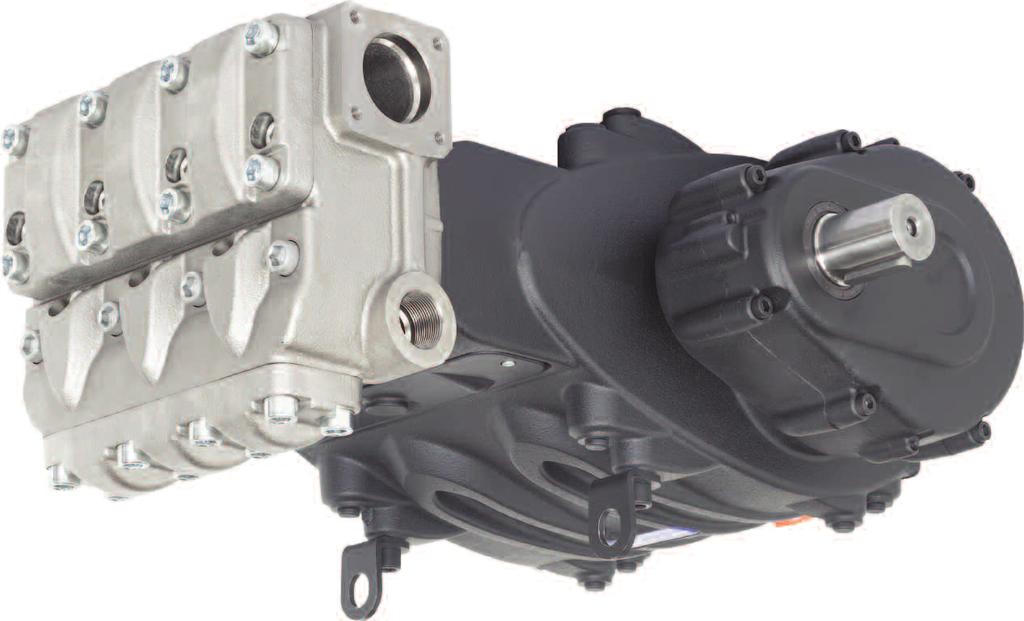

1 MW/S 8 Repair Manual MWS45A-MWS50A-MWS55A MW32A-MWS36A-MWS40A General Pump is a member of the Interpump Group
2 INDEX 1. INTRODUCTION Page 3 2. REPAIR INSTRUCTIONS Page Repairing Mechanical Parts Page Disassembly of Mechanical Parts Page Assembly of Mechanical Parts Page Increase and Reduction Classes Page Repairing Hydraulic Parts Page Dismantling the MW32A, MWS36A, MWS40A Head-Valve Units...Page Assembling the MW32A, MWS36A, MWS40A -Valve Units Page Dismantling the MWS45A, MWS506A, MWS55A Head-Valve Units.Page Assembling the MWS45A, MWS506A, MWS55A Head-Valve Units.Page Dismantling the Plunger Unit-Supports-Seals Page Assembling the Plunger Unit-Supports-Seals Page SCREW CALIBRATION Page REPAIR TOOLS Page MAINTENANCE LOG Page 54 Page 2


3 1. INTRODUCTION This manual describes the instructions for Repairing MW/S Series pumps, and must be carefully read and understood before performing any repair intervention on the pump. Proper pump operation and longevity depend on the correct use and maintenance. General Pump declines any responsibility for damage caused by the misuse or the non-observance of the instructions described in this manual. 2. REPAIR INSTRUCTIONS 2.1 Repairing Mechanical Parts Mechanical parts repair must be performed after removal of oil from the casing. To drain the oil, remove the oil dipstick, (1, fig. 1) and then the draining plug (2, fig. 1). The oil must be placed in a suitable container and disposed of in special centers. It absolutely must not be discarded into the environment. Page 3

, unscrewing the 6 M10 screws (1, fig.")

4 2.1.1 Disassembly of Mechanical Parts The correct sequence is the following: Completely drain the oil from the pump, then disassemble the casing cover (and relative o-ring), unscrewing the 6 M10 screws (1, fig. 2). Remove the tab from the PTO shaft (2, fig. 3). Unscrew the reduction gear cover fixing screws (1, fig. 4). Page 4
 with the function of extractors in the holes and two sufficiently long M10")


5 Position the 3 grub screws or M8 threaded screws (1, fig. 5) with the function of extractors in the holes and two sufficiently long M10 screws with the function of supporting the cover (2, fig. 5). Slowly screw in the 3 M8 screws (1, fig. 6) with the function of extractors to fully remove the cover unit and pinion. Complete disassembly of the reduction gear cover from the pinion is possible following these steps: Remove the retaining ring Ø120 (1, fig. 7) Page 5


 from the pinion.")

6 Separate the pinion from the cover, working with an extractor hammer on the pinion itself (1, fig. 8). Remove the retaining ring Ø55 (1, fig. 9) and the bearing support ring (1, fig. 10) from the pinion. Extract the seal ring from the reduction gear cover, working from the inner side of the cover (1, fig. 11). Page 6

.")

. Remove the key from the shaft")
7 Unscrew the screws holding in the ring gear (1, fig. 12) and remove it (1, fig. 13). Remove the ring gear (1, fig. 14). Where necessary, it is possible to utilize an extractor hammer to be applied on the 2 M8 holes (2, fig. 14). Remove the key from the shaft (1, fig. 15). Page 7
.")


8 Remove the ring gear support ring (1, fig. 16). Unscrew the connecting rod screws (1, fig. 17). Remove the connecting rod caps with the lower semi-bearings, taking special care of the disassembly sequence during disassembly. The con-rod caps and their relative half supports must be reassembled in exactly the same order and coupling with which they were disassembled. To avoid possible errors, caps and half-supports have been numbered on one side (1, fig. 18). Page 8


. Remove the three upper")
.")
9 Advance the half supports completely in the direction of the pump head to allow the crankshaft to come out. To facilitate this operation, use special tool (p/n F ) (1, fig. 19). Remove the three upper half-bearings of the half supports (1, fig. 20). Unscrew the reduction gear box fixing screws (1, fig. 22). Page 9


.")


10 Position the 3 grub screws or M8 threaded screws (1, fig. 23) with the function of extractors in the holes and two sufficiently long M10 screws with the function of supporting the reduction gear box (2, fig. 23). Slowly screw in the 3 M8 screws (1, fig. 24) to prevent the box from tilting too far and getting locking in the housing. Remove the box while supporting the shaft to prevent damage (1, fig. 25) Unscrew the bearing cover fixing screws from the opposite side (1, fig. 26 and fig. 27). Page 10


11 Position the 3 grub screws or M8 threaded screws (1, fig. 28) with the function of extractors in the holes. Slowly screw in the 3 M8 screws (1, fig. 29) to prevent the cover from tilting too far and getting locked in the housing. Remove the bearing cover while supporting the shaft to prevent damage (1, fig. 30). Remove the crankshaft from the PTO side (1, fig. 31) Page 11


12 In the event that it is necessary to replace one or more con-rods or plunger guides, operate as follows: Unscrew the screws with tool #F to unlock the con-rods (1, fig. 32) and then extract the con-rod plunger guide units from the back casing opening (1, fig. 33). It is now possible to disassemble the plunger guide seal rings, taking care to not damage the plunger guide sliding rod. Whenever it becomes necessary to replace the plunger guide seal rings without dismantling the entire mechanical part, it is possible to extract the seal rings with the use of tool #F operating as follows: Insert the tool between the rod and the seal ring (1, fig. 34) and, with the extractor hammer, complete insertion of the tapered section inside the seal ring (1, fig. 35). Page 12


.")

13 Extract the seal ring using the tool extractor hammer (1, fig. 36). Remove the two spindle locking retaining rings Ø120 (1, fig. 37). Remove the spindle (1, fig. 38 and extract the con-rod (1, fig. 39). Page 13

14 Couple the half supports to the previously disassembled caps, referring to the numbering (1, fig. 40). To separate the rod from the plunger guide, unscrew the hexagonal head M10 screws with a 17mm socket wrench (1, fig. 41), blocking the rod with the 36mm fork spanner. Page 14
 and join the rod to the plunger guide by means of M20 x 35 screws (1, fig. 43).")
 as indicated in paragraph 3 Screw Tightening Calibration. Insert the con-rod in the plunger guide (1, fig. 39) and then insert the spindle (1, fig.")

.")
15 2.1.2 Assembly of Mechanical Parts Proceed with assembly following the reverse order indicated in point The proper sequence is as follows: Assemble the rod to the plunger guide. Insert the elastic pin Ø5 in its hole on the plunger guide (1, fig. 42) and join the rod to the plunger guide by means of M20 x 35 screws (1, fig. 43). Lock in the rod in correspondence with the two planes with a 36mm fork spanner (1, fig. 44) and proceed with calibration with a torque wrench (1, fig. 45) as indicated in paragraph 3 Screw Tightening Calibration. Insert the con-rod in the plunger guide (1, fig. 39) and then insert the spindle (1, fig. 38). Apply the two shoulder retaining rings (1, fig. 37). Assembly has been carried out properly if the con-rod foot, plunger guide and spindle rotate freely. Separate the caps from the half supports. Proper coupling can be verified by the numbering on the side (1, fig. 40). After having checked casing cleaning, proceed with assembly of half support-plunger guide unit inside casing rods (1, fig. 33). Insertion of the half support-plunger guide unit in the casing must be made with the half bearings set in the direction in which numbers are visible from above. Page 15


16 Block the three units with the use of special tool #F (1, fig. 32). Pre-assemble the ring inside the crankshaft bearings (on both sides of the shaft down to the stroke) using special tool #F (1, fig. 47). The inner and outer rings of the bearings must be reassembled keeping the same coupling with which they were disassembled. Insert the shaft from the PTO side, taking care not to hit the previously assembled con-rod shanks (1, fig. 48) and (1, fig. 49). The crankshaft must always be assembled with the PTO on the opposite side with respect to the 1/2 NPT holes for the oil discharge plugs on the pump casing (1, fig. 51). Page 16
.")


.")


17 Fully insert the shaft in the casing (1, fig. 50 and fig. 51). Pre-assemble the outer ring of the pinion bearing on the reduction gear with the aid of special tool #F (1, fig. 52), inserting fully down to end stroke (1, fig. 53). From the opposite side of the reduction gear box, pre-assemble the external ring of the crankshaft bearing with the use of tool #F (1, fig. 54), inserting fully down to end stroke (1, fig. 55). Page 17

, inserting fully down to end stroke (1,")

.")
.")
18 Repeat this operation on the bearing box, pre-assembling the external crankshaft bearing ring with the help of special tool #F (1, fig. 56), inserting fully down to end stroke (1, fig. 57). Insert the side seal on the bearing cover (1, fig. 58) and lift the crankshaft to favor cover insertion (1, fig. 59). Assemble the bearing cover (and relative seal) using an extractor hammer (1, fig. 60). Position the bearing cover in such a way that the Pratissoli logo is perfectly horizontal. Page 18


.")
19 Tighten the 8 M10 x 30 screws (1, fig. 61). Calibrate the screws with a torque wrench as indicated in paragraph 3 Screw Tightening Calibration. From the opposite side, insert the side seal on the reduction gear box 91, fig. 62) and lift the crankshaft to favor cover insertion (1, fig. 63). Assemble the reduction gear box (and relative seal) using an extractor hammer (1, fig. 64). Page 19
. Insert the upper half-bearings between the con-rods and the shaft (1, fig. 66).")
 ensuring that the half-bearing reference notches are positioned in their housing on the cap (1, fig.")

20 Tighten the 8 M10 x 40 screws (1, fig. 56). Calibrate the screws with a torque wrench as indicated in paragraph 3 Screw Tightening Calibration. Remove the tool for blocking the con-rods #F (1, fig. 32). Insert the upper half-bearings between the con-rods and the shaft (1, fig. 66). For proper assembly of the half-bearings, ensure that the reference tab on the half-bearings are positioned in their housing on the half support (1, fig. 67). Apply the lower half-bearings to the caps (1, fig. 68) ensuring that the half-bearing reference notches are positioned in their housing on the cap (1, fig. 68). Fasten the caps to the half supports by means of M10 x 1.5 x 80 screws (1, fig. 69). Note the correct assembly direction of the caps. Numbering must be turned upward. Calibrate the screws with a torque wrench as indicated in paragraph 3 Screw Tightening Calibration), bringing the screws to tightening torque at the same time. Page 20


21 After finishing this operation, verify that the con-rods have axial clearance in both directions. Insert the plunger guide seal rings in their casing housing by means of a special tool #F (1, fig. 70). Insert the O-ring on the rear cover (1, fig. 71) and assemble the cover on the casing with the aid of 6 M10 x 30 screws (1, fig. 72). Page 21


 to end stroke (1, fig. 74).")
 and insert the ring gear on the shaft (1, fig. 76).")
22 Take care to fully and properly insert the O-ring in its housing on the cover to prevent damage during screw tightening. Calibrate the screws with a torque wrench as indicated in paragraph 3 Screw Tightening Calibration. Insert the ring gear support ring in the crankshaft shank (1, fig. 73) to end stroke (1, fig. 74). Apply key 22 x 14 x 80 in the shaft housing (1, fig. 75) and insert the ring gear on the shaft (1, fig. 76). The ring gear must be assembled making sure that the two M8 holes (to be used for extraction) be turned outward of the pump (1, fig. 76). Page 22
 using 2 M10 x 25 screws.")


 and insert the O-ring (1, fig. 80).")

23 Fasten the ring gear stop (1, fig. 77) using 2 M10 x 25 screws. Calibrate the screws with a torque wrench as indicated in paragraph 3 Screw Tightening Calibration (1, fig. 78). Apply the two Ø10 x 24 pins on the reduction gear box (1, fig. 79) and insert the O-ring (1, fig. 80). Complete assembly of the pinion on the reduction gear cover, proceeding as follows: Pre-assemble the inner bearing ring 40 x 90 x 23 on the pinion (1, fig. 81) positioning it to end stroke. Page 23

 positioning it to end stroke using")
")
. Insert the pinion pre-assembled")

24 From the other side of the pinion, pre-assemble the bearing 55 x 120 x 29 (1, fig. 82) positioning it to end stroke using tool #F (1, fig. 83). Insert the bearing support ring (1, fig. 84) and position the retaining ring Ø55 (1, fig. 85). Insert the pinion pre-assembled inside its housing in the reduction gear cover, with the aid of an extractor hammer (1, fig. 86). Page 24
 and fasten them with 7 M10 x 40 screws (1, fig. 89).")


25 Insert the retaining ring Ø120 in the housing (1, fig. 87). Assemble the reduction gear cover with the aid of an extractor hammer (1, fig. 88) and fasten them with 7 M10 x 40 screws (1, fig. 89). Take care to properly couple the two components on the bearing 40 x 90 x 23. Calibrate the screws with a torque wrench as indicated in paragraph 3 Screw Tightening Calibration. Insert the seal ring inside the reduction gear cover with the use of special tool #F (1, fig. 90). Before proceeding with seal ring assembly, check lip seal conditions. If replacement is necessary, position the new ring on the bottom of the groove as indicated in fig. 91. If the shaft should present a diameter wear corresponding to the lip seal, to prevent grinding, position the ring in the second stroke as indicated in fig. 91. Page 25
 and tighten with 2+2 M16 x 14 screws (1, fig. 93).")


26 To prevent damage to the seal ring, take special care when inserting the seal ring on the pinion. Apply O-rings on the inspection covers (1, fig. 92) and tighten with 2+2 M16 x 14 screws (1, fig. 93). Calibrate the screws with a torque wrench as indicated in paragraph 3 Screw Tightening Calibration. Insert the key 14 x 9 x 60 on the pinion. Apply plugs and lifting brackets with the use of M16 x 30 screws (1, fig. 94). Calibrate the screws with a torque wrench as indicated in paragraph 3 Screw Tightening Calibration:. Insert oil in the casing as indicated in the use and maintenance manual point 7.4 Page 26
 0.25 F90928100 F90928400 Ø79.75 0/0.02 Ra 0.4 Rt 3.")

27 2.1.3 Increase and Reduction Classes Recovery classes (mm) TABLE OF REDUCTIONS FOR CRANKSHAFTS AND CON-ROD HALF-BEARINGS P/N Half-bearing Upper P/N Half-bearing Lower Correction on the shaft pin diameter (mm) 0.25 F F Ø /0.02 Ra 0.4 Rt F F Ø /0.02 Ra 0.4 Rt 3.5 Recovery classes (mm) INCREASE TABLE FOR PUMP CASING AND PLUNGER GUIDE P/N Plunger Guide Adjustments on the Pump Casing housing (mm) 1.00 F Ø71 H /0 Ra 0.8 Rt Repairing Hydraulic Parts Dismantling the MW32A, MWS36A, MWS40A Head-Valve Units The head requires preventive maintenance as indicated in the use and maintenance manual. Operations are limited to inspection or replacement of valves, if necessary. Proceed as follows to extract valve groups: Unscrew the 8 M16 x 55 screws of the valve cover (1, fig. 95) and remove the cover (1, fig. 96). Page 27

.")
 to be applied on")
28 Extract the valve plug with the use of an extractor hammer to be applied on the M10 hole of the valve plug (1, fig. 97). Remove the spring (1, fig. 98). Extract the outlet valve unit with the use of an extractor hammer (p/n F ) to be applied on the M10 hole of the valve guide (1, fig. 99). Page 28

.")
 to be applied on the M10")
29 Remove the valve housing spacer ring (1, fig. 100). Remove the valve guide spacer inserting 8mm hexagon spanner in the housing and lifting it to facilitate removal (1, fig. 101). Extract the suction valve unit with the use of an extractor hammer (#F ) to be applied on the M10 hole of the valve guide (1, fig. 102). Page 29
 as indicated. Unscrew the valve opening device by means of a 30mm spanner (1, fig. 104).")
. Complete disassembly removing the 1/4 NPT plugs on the front of the head.")
30 Where extraction of the suction valve unit is especially difficult (i.e. incrustations due to prolonged lack of use), use an extractor tool #F (1, fig. 103) as indicated. Unscrew the valve opening device by means of a 30mm spanner (1, fig. 104). Remove the suction and outlet valve units, unscrewing an M10 screw in such a way to press on the inner guide and remove the valve guide from the valve housing (1, fig. 105). Complete disassembly removing the 1/4 NPT plugs on the front of the head. Page 30
. 2.")


31 It is now possible to remove the head from the pump casing, unscrewing the 8 M16 x 180 screws (1, fig. 106). During assembly of the head, pay special attention not to hit the plungers (1, fig. 107) Assembling the MW32A, MWS36A, MWS40A - Valve Units Pay particular attention to the conditions of the various components and replace if necessary. At every valve inspection, replace all O-rings both in the valve unit and in the valve plugs. Before repositioning the valve unit, thoroughly clean and dry the relative housings on the head indicated by the arrows (1, fig. 108) Proceed with reassembly following the reverse order indicated in Page 31
, taking care not to invert the previously disassembled springs.")

 in the head, taking care to")

32 Assemble the suction and outlet valve units (fig. 109 and fig. 110), taking care not to invert the previously disassembled springs. To facilitate insertion of the valve guide in its housing, you can use a pipe resting on the horizontal guide planes (fig. 111) and use an extractor hammer acting on the whole circumference. Proceed with insertion of the valve units (suction and outlet) in the head, taking care to follow the correct insertion sequence of O-rings and anti-extrusion rings. The proper sequence of valve unit assembly on the head is as follows: Insert the anti-extrusion ring, exploded position 5 from the Owner s Manual (1, fig. 112). Insert the O-ring, exploded position 6 from the Owner s Manual (1, fig. 113). Page 32

 and then the spacer (1, fig. 115).")

, resting on the spacer (1, fig. 117).")

33 Ensure that the O-ring and anti-extrusion ring are perfectly placed in their housings. Insert the suction valve unit (1, fig. 114) and then the spacer (1, fig. 115). The complete valve unit must be fully inserted into the bottom and should look like the image in fig Insert the valve housing spacer ring (1, fig. 116), resting on the spacer (1, fig. 117). Assemble the O-ring, exploded position 6 from the Owner s manual (1, fig. 118) and the anti-extrusion ring, (2, fig. 118) on the outlet valve housing. Page 33
. The valve unit must be fully")


34 Insert the outlet valve unit (1, fig. 119). The valve unit must be fully inserted into the bottom and should look like the image in 1, fig Insert the anti-extrusion ring, exploded view position 18 from the Owner s Manual (1, fig. 121). Insert the O-ring, exploded view position 19 from the Owner s Manual (1, fig. 122). Page 34


 and the spring (1, fig. 125).")

35 Pay special attention to O-ring insertion in 1, fig Use special tool #F to prevent the O-ring from damage during insertion. Insert the valve housing ring (1, fig. 124) and the spring (1, fig. 125). Assemble the O-ring, exploded view position 19 from the Owner s Manual (1, fig. 126) and the anti-extrusion ring, exploded view position 23 (2, fig. 126) on the outlet valve plug. Page 35

. Assemble the pump casing head (1, fig.")
36 Insert the valve plug housing complete with O-ring and anti-extrusion rings. After having completed assembly of the valve units and the valve plug, apply the valve cover (1, fig. 127) and screw in the 8 M16 x 55 screws (1, fig. 128). Apply 6 front O-rings on the pump casing (1, fig. 129). Assemble the pump casing head (1, fig. 130) taking care not to hit the plungers and screw in the 8 M16 x 180 screws (1, fig. 131). Page 36


37 Proceed with calibration of the M16 x 180 screws with a torque wrench as indicated in paragraph 3 Screw Tightening Calibration. Tighten the 8 M16 x 180 screws starting cross-wise from the 4 inner screws, to then continue with the 4 outer screws, always tightening cross-wise. Calibrate the M16 x 55 cover screws with a torque wrench as indicated in paragraph 3, Screw Tightening Calibration. Apply the valve opening devices (1, fig. 132) and screw them in with the use of a 30 mm spanner (1, fig. 133). Apply the 1/4 NPT plugs on the front of the head with relative O-rings. Proceed with calibration of the 1 plugs with a torque wrench as indicated in paragraph 3 Screw Tightening Calibration Dismantling the MWS45A, MWS50A and MWS55A Head-Valve Units The head requires preventive maintenance as indicated in the Owner s Manual. Operations are limited to inspection or replacement of valves, if necessary. Proceed as follows to extract valve groups: Unscrew the 8 M16 x 45 screws of the outlet valve cover (1, fig. 134) and remove the cover (1, fig. 135). Page 37
 to be applied on the")

. Extract the suction valve unit with the use")

38 Extract the outlet valve unit with the use of an extractor hammer (#F ) to be applied on the M10 hole of the valve guide (1, fig. 136). Unscrew the 8 M16 x 45 screws of the suction valve cover (1, fig. 137) and remove the cover (1, fig. 138). Extract the suction valve unit with the use of an extractor hammer (#F ) to be applied on the M10 hole of the valve guide (1, fig. 139). Page 38


39 Unscrew the valve opening device by means of a 30 mm spanner (1, fig. 140). Remove the suction and outlet valve units, unscrewing an M10 screw in such a way to press on the inner guide and remove the valve guide from the valve housing. (1, fig. 141). Complete disassembly removing the 1/4 plugs on the front of the head and the 1/2 plugs on the lower part of the head. It is now possible to remove the head from the pump casing, unscrewing the 8 M16 x 150 screws (1, fig. 142). During assembly of the head, pay special attention not to hit the plungers (fig. 143). Page 39


40 2.2.4 Assembling the MWS45A, MWS50A and MWS55A Head-Valve Units Pay particular attention to the conditions of the various components and replace if necessary. At every valve inspection, replace all O-rings both in the valve unit and in the valve plugs. Before repositioning the valve unit, thoroughly clean and dry the relative housings on head indicated by the arrows (1, fig. 144). Proceed with reassembly following the reverse order indicated in point Assemble the suction and outlet valve units (fig. 145 and fig. 146). fig. 144 To facilitate insertion of the valve guide in its housing, you can use a pipe resting on the horizontal guide planes (fig. 147) and use an extractor hammer acting on the whole circumference. Proceed with insertion of the valve units (suction and outlet) in the head, taking care to follow the correct insertion sequence of O-rings and anti-extrusion rings. Page 40


. The complete valve unit must be fully inserted into the")
41 The proper sequence of valve unit assembly on the head is as follows: During suction, insert the anti-extrusion ring, exploded view position 6 from the Owner s Manual, (1, fig. 148). Insert the O-ring, exploded view position 7 in the Owner s Manual, (1. fig. 149). Ensure that the O-ring and anti-extrusion ring are perfectly placed in their housings. Insert the suction valve unit (1, fig. 150). The complete valve unit must be fully inserted into the bottom and should look like the image in fig Page 41
.")

 and screw in the 8 M16 x 45 screws (1,")

42 Insert the front O-ring in the suction valve (1, fig. 152). After having completed assembly of the suction valve units, apply the suction valve cover (1, fig. 153) and screw in the 8 M16 x 45 screws (1, fig. 154). Proceed with outlet valve assembly: Insert the anti-extrusion ring, exploded view position 23 from the Owner s Manual, (1, fig. 155). Page 42
.")


43 Insert the O-ring, exploded view position 24 from the Owner s Manual, (1, fig. 156). Ensure that the O-ring and anti-extrusion ring are perfectly placed in their housings. Insert the outlet valve unit (1, fig. 157). The complete valve unit must be fully inserted into the bottom and should look like the image in fig Insert the front O-ring in the outlet valve (1, fig. 159). Page 43
 and screw in the 8 M16 x 45 screws (1, fig. 161).")

.")
44 After having completed assembly of the outlet valve units, apply the outlet valve cover (1, fig. 160) and screw in the 8 M16 x 45 screws (1, fig. 161). Apply 6 front O-rings on the pump casing (1, fig. 162). Assembly the pump casing head (1, fig. 163) taking care not to hit the plungers and screw in the 8 M16 x 150 screws (1, fig. 164). Proceed with calibration of the M16 x 150 screws with a torque wrench as indicated in paragraph 3, Screw Tightening Calibration. Page 44


45 Tighten the 8 M16 x 180 screws starting cross-wise from the 4 inner screws, then continue with the 4 outer screws, always tightening cross-wise. Calibrate the M16 x 45 suction and outlet cover screws with a torque wrench as indicated in paragraph 3 screw Tightening Calibration. Apply the valve opening devices (1, fig. 165) and screw them in with the use of a 30 mm spanner (1, fig. 166). Apply the 1/2 plugs on the lower part of the head with relative washers. Proceed with calibration of the 1/2 plugs with a torque wrench as indicated in paragraph 3 Screw Tightening Calibration. Apply the 1/4 plugs on the front of the head with relative O-rings. Proceed with calibration of the 1/4 plugs with a torque wrench as indicated in paragraph 3 Screw Tightening Calibration Dismantling the Plunger Unit - Supports - Seals The plunger unit requires preventive checks as indicated in the preventive maintenance table in the Owner s Manual. Maintenance is limited to visual inspection of any drainage from the hole present on the lower inspection cover. If abnormalities / variations on the outlet pressure gauge or dripping from the drainage hole circuit are detected, the seal packings will have to be checked and replaced. To access the plunger unit, unscrew the M18 x 180 screws (for MW32A, MWS36A and MWS40A) or M16 x 150 screws (for MWS45A, MWS50A and MWS55A) and remove the head. Remove the head taking care to avoid hitting the plungers. Page 45


46 Disassemble plungers unscrewing the fixing screws (1, fig 167). Remove the plunger from the seal support and check that its surfaces do not present any scratches, signs of wear or cavitation. Remove the upper inspection cover, unscrewing the 2 fixing screws (1, fig. 168). Manually turn the shaft in such a way to bring the 3 plungers to the upper dead center position. Insert the buffering tool (#F ) between the plunger guide and the plunger (1, fig. 169). Page 46


.")
47 Turning the shaft, have the plunger guide move forward so that the buffer, moving ahead, can expel the seal support and the entire plunger unit (1, fig. 170). Extract the seal support unit and the buffering tool. Remove the seal support bottom O-ring should it remain inside the pump casing (1, fig. 171). Remove the spray rings from the plunger guides (1, fig. 172). Page 47


, taking")
48 Separate the seal support from the liner (1, fig. 173) to access the pressure seals (1, fig. 174). To remove the low pressure seal, use a thickness gauge or another tool which will not damage the seal support housing (1, fig. 175) Re-assembling the Plunger Unit - Support - Seals Proceed with re-assembly following the reverse order indicated in point Replace the pressure seals moistening the lips with silicone grease (without spreading it), taking extra care not to damage them during liner insertion. The O-rings and the low pressure seals must be replaced at each disassembly. Page 48


.")
49 Insert the low pressure seal in the seal support (1, fig. 176) paying attention to the mounting direction which requires that the sealing lip be set forward (toward the head). Install the head ring (1, fig. 177), the high pressure seal (1, fig 178) and the restop ring (1, fig. 179). Join the seals supports to the liner (1, fig. 180). Page 49
.")


 and fasten them as per 1, fig. 184.")
50 Position the spray hood in the plunger guide housing (1, fig. 181). Insert the Ø10 x 18 x 0.9 washer in the plunger fixing screw (1, fig. 182). Install the plungers on their respective guides (1, fig. 183) and fasten them as per 1, fig Calibrate the screws with a torque wrench as indicated in paragraph 3 Screw Tightening Calibration. Page 50


. Ensure that the liner-support")
.")

51 Insert the O-ring inside the pump casing (1, fig. 185) and then the previously-assembled liner-seal support block (complete with the same O-ring) to end stroke (1, fig. 186). Ensure that the liner-support block is positioned correctly down to the bottom of the housing (1, fig. 187). Install the front O-ring in the liner (1, fig. 188) and the recirculation hole O-ring (1, fig. 189). Page 51

52 Insert the O-ring on the inspection covers (1, fig. 190) and assemble the covers with the use of 2+2 M6 x 14 screws (1, fig. 191). Calibrate the screws with a torque wrench as indicated in paragraph 3, Screw Tightening Calibration. 3. SCREW CALIBRATION Screws are to be fastened exclusively using a torque wrench. Description Exploded View Position (From Owner s Manual) Fastening Ft. Lbs. Fastening Nm Crankcase cover screws M10 x (MW32A, MWS36A, MWS40A) Crankcase cover screws M10 x (MWS45A, MWS50A, MWS55A) Casing Plug, 1/2 x (MW32A, MWS36A, MWS40A) Casing Plug, 1/2 x (MWS45A, MWS50A, MWS55A) Lifting Bracket M16 x 30 Screw 51 (MW32A, MWS36A, MWS40A) Lifting Bracket M16 x 30 Screw 53 (MWS45A, MWS50A, MWS55A) Reducer cover screw M10x40 81 (MW32A, MWS36A, MWS40A) Reducer cover screw M10x40 83 (MWS45A, MWS50A, MWS55A) Ring gear stopper screw M10 x (MW32A, MWS36A, MWS40A) Ring gear stopper screw M10 x (MWS45A, MWS50A, MWS55A) Reducer case screw M10x40 81 (MW32A, MWS36A, MWS40A) Reducer case screw M10x40 83 (MWS45A, MWS50A, MWS55A) Upper and lower cover screw M6x14 60 (MW32A, MWS36A, MWS40A) Upper and lower cover screw M6x14 62 (MWS45A, MWS50A, MWS55A) Bearing cover screw m10x30 89 (MW32A, MWS36A, MWS40A) Bearing cover screw m10x30 9 (MWS45A, MWS50A, MWS55A) Connecting rod screw M10x1.5x80 53 (MW32A, MWS36A, MWS40A) 47.9* 65* Connecting rod screw M10x1.5x80 55 (MWS45A, MWS50A, MWS55A) 47.9* 65* Plunger guide screw M10x35 48 (MW32A, MWS36A, MWS40A) Plunger guide screw M10x35 50 (MWS45A, MWS50A, MWS55A) Plunger guide screw M10x (MW32A, MWS36A, MWS40A) Plunger guide screw M10x (MWS45A, MWS50A, MWS55A) Valve Cover Screw M16 x 55 (MW32A, MWS36A, MWS40A) Valve Cover Screw M16 x 45 (MWS45A, MWS50A, MWS55A) Head plug 1/4 (MWS45A, MWS50A, MWS55A) Head plug 1/4 x13 14 (MW32A, MWS36A, MWS40A) Head plug 1/4 x13 21 (MWS45A, MWS50A, MWS55A) Head screw M16x ** 333** Head screw M16x ** 333** Valve opening device Ref Rev.C * Achieve coupling torque tightening screws at the same time. ** Tightening sequence always cross-wise starting from the 4 internal screws then the 4 external screws (see fig. 131). Page 52
53 4. REPAIR TOOLS Pump maintenance may be carried out using simple tools for assembling and disassembling components. The following tools are available: KIT B B D For Assembly: Shaft (con-rod interlocking) F Bearing on crankshaft F Pinion bearing on reduction gear box F Crankshaft bearing on the reduction gear box F Crankshaft bearing on the bearing cover F Oil seal insertion tool, MW/S F Oil seal insertion cone, MW/S F Bearing on pinion F Pinion seal ring F plus F Outlet valve housing O-ring MW32A, MWS36A, MWS40A F KIT For Disassembly: B Oil seal extraction tool F B Bolt for oil seal extraction tool Shaft (con-rod interlocking) F D Outlet and suction valve units F D Suction valve housing MW32A, MWS36A, MWS40A F C Cylinder removal tool w/handle, MW/S series F A Slide hammer, MW/S valve tool F A 8mm x 10mm adapter, MW/S slide hammer F A 32mm collett for MW/S discharge seat A 42mm collett for MW/S inlet valve seat RECOMMENDED REPAIR KITS FKITMWV - MWS45A, MWS50A, MWS55A Valve removal / Installation Tool Kit A Includes: F Slide Hammer Qty. 1 F mm Adapter Qty mm Collet Qty mm Collet Qty. 1 FKITMWP - Piston Oil Seal Removal / Installation Tool Kit B Includes: F Insertion Tool Qty. 1 F Insertion Cone Qty. 1 F Extraction Tool Qty Extraction Tool Bolt Qty. 1 F Cylinder Removal Tool with Handle - MW - Tool Kit C Includes: F Spacer with Handle Qty Splined Dummy Shaft Tool, 14 TPI Qty. 1 FKITMKVHP - MW32A, MWS36A, MWS40A Valve removal / Installation Tool Kit D Includes: F Outlet valve housing O-ring Qty. 1 F Outlet and suction valve units Qty Suction valve housing Qty. 1 Page 53
54 MAINTENANCE LOG HOURS & DATE OIL CHANGE GREASE PACKING REPLACEMENT PLUNGER REPLACEMENT VALVE REPLACEMENT GP Companies, Inc Northland Drive Mendota Heights, MN Phone: Fax: Page 54
Repair Manual MK40A-MK45A-MK50A MK55A-MK60A-MK65A. Ref Rev.C General Pump is a Member of The Interpump Group
 MK Repair Manual MK40A-MK45A-MK50A MK55A-MK60A-MK65A General Pump is a Member of The Interpump Group 8 INDEX 1. INTRODUCTION..................................................Page 3 2. REPAIR INSTRUCTIONS...........................................Page
LK36-LK40-LK45 LK50-LK55-LK60
 LK Repair Manual LK36-LK40-LK45 LK50-LK55-LK60 INDEX 1. INTRODUCTION..................................................Page 3 2. REPAIR INSTRUCTIONS...........................................Page 3 2.1
MKS. MKS Series MKS 40 MKS 45 MKS 50 MKS 55 MKS 60 MKS 65. Repair Manual
 MKS Series MKS 40 MKS 45 MKS 50 MKS 55 MKS 60 MKS 65 Repair Manual INDEX. INTRODUCTION 3 2. REPAIR INSTRUCTIONS 3 2. Crank Mechanism Repair...3 2.. Crank Mechanism Disassembly...4 2..2 Crank Mechanism
Click Here to Go Back
 Click Here to Go Back Fig. -94 Fig. -97 CC42D 10. Remove the cap screw securing the gear shift stopper plate pin retainer; then remove the retainer. Fig. -95 CC45D 12. Remove the link arm and account for
Maintenance Information
 16601023 Edition 2 January 2014 Air Impact Wrench 2705P1 Maintenance Information Save These Instructions Product Safety Information WARNING Failure to observe the following warnings, and to avoid these
REPAIR INSTRUCTIONS. Cat. No Cat. No MILWAUKEE ELECTRIC TOOL CORPORATION. SDS Max Demolition Hammer. SDS Max Rotary Hammer
 Cat. No. 9-0 SDS Max Demolition Hammer Cat. No. -0 SDS Max Rotary Hammer MILWAUKEE ELECTRIC TOOL CORPORATION W. LISBON ROAD BROOKFIELD, WISCONSIN 00-0 8-9-0 d 000 8-9-0 d Special Tools Require Forcing
General Four-Way Operation, Maintenance & Service Manual
 General Four-Way Operation, Maintenance & Service Manual SCOPE Included in the following pages you will find assembly drawings, exploded views, parts lists, assembly tips, operational descriptions and
ELECTRIC TOOL CORPORATION
 Cat. No. -0 / Hex Demolition Hammer Cat. No. 0-0 Spline Rotary Hammer MILWAUKEE ELECTRIC TOOL CORPORATION W. LISBON ROAD BROOKFIELD, WISCONSIN 00-0 -9-00 d 000 -9-00 d SpecialTools Require Forcing discs
w w w. h d o n l i n e s h o p. d e TIMKEN BEARING CONVERSION TOOL GENERAL INSTALLATION -J04672 REV Kit Number Models
 -J067 REV. 008-07- GENERAL Kit Number 8-08 Models TIMKEN BEARING CONVERSION TOOL For model fitment information, see the P&A Retail Catalog or the Parts and Accessories section of www.harley-davidson.com
BRAVO STERN DRIVE 3 C BRAVO ONE
 RAVO STERN DRIVE 3 C 22439 RAVO ONE Table of Contents Page Specifications............................... 3C-1 Torque Specifications..................... 3C-1 Preloads................................ 3C-1
DO35 MAINTENANCE INSTRUCTIONS
 CUSTOMER INFORMATION SHEET NO. 038 DO35 MAINTENANCE INSTRUCTIONS (DO35 V3 LAUNCHED PRODUCTION JUNE 2017) Table of Contents 1.0 Replacing Spindle Bushes V3... 22 2.0 Replacing Locking Mechanism V3... 6
Series 760 Heavy Duty Fixed Displacement Motor. Parts and Repair Manual
 Series 760 Heavy Duty Fixed Displacement Motor Parts and Repair Manual Series 760 Fixed Displacement Motor Contents Introduction 3 ID Tag Information 3 Parts List 4 Parts Drawing 5 Disassembly Instructions
Removing Right-Side. Components. Right-Side. Components. Click Here to Go Back AT THIS POINT
 Click Here to Go Back NOTE: There is an oil passage beneath the driven gear/drive gear assembly. This passage should be plugged prior to removing the driven gear and drive gear. Failure to do so could
OTECO INC. MODEL ,000 PSI 4-1/16 PORT DM GATE VALVE MAINTENANCE MANUAL
 Page 1 of 7 OTECO INC. MODEL 45 4 5,000 PSI 4-1/16 PORT DM GATE VALVE MAINTENANCE MANUAL Page 2 of 7 TABLE OF CONTENTS 1. Assembly Blowout 2. Repair Kit Contents & Technical Specifications 3. Disassembly
Additional Information
 NUMBER: 1 34 13 S.M. REF.: Listed in Table ENGINE: EPA04/07 Series 60 DATE: January 2013 SUBJECT: CHECKING CYLINDER LINER PROTRUSION ADDITIONS, REVISIONS, OR UPDATES Publication Number Platform Section
The Virgo/Libra Steam Engine
 The Virgo/Libra Steam Engine Congratulations on becoming the owner of a Virgo or Libra Steam Engine. With careful use and maintenance it will give many years of satisfying performance. Contents 1) Notes
A-PDF Split DEMO : Purchase from to remove the watermark SHAFT DRIVE
 SHAFT DRIVE 4-1 A-PDF Split DEMO : Purchase from www.a-pdf.com to remove the watermark SHAFT DRIVE CONTENTS SECONDARY BEVEL GEARS... 4-2 CONSTRUCTION... 4-2 REMOVAL... 4-4 DISASSEMBLY... 4-4 INSPECTION...
PARTS LIST FOR MODEL 7000 SERIES - 17/46
 ITEM PARTS LIST FOR MODEL 7000 SERIES - 17/46 1 Rotor 3 Housing 1 4 End Plate 6 Drive End Cover 1 7 Free End Cover 1 8 Timing Gear Set 1 9 Bearing, Drive End 10 Bearing, Free End 1 Lip Seal, Viton 4 13
Fisher 667 Diaphragm Actuators Size 80 and 100
 Instruction Manual 667 Size 80 and 100 Actuators Fisher 667 Diaphragm Actuators Size 80 and 100 Contents Introduction... 1 Scope of Manual... 1 Description... 2 Specifications... 2 Maximum Pressure Limitations...
No September, Char-Lynn. Power Steering. Repair Information. 20 Series Steering Control Unit 001
 Char-Lynn Power Steering No. 7-313 September, 1997 Repair Information 20 Series Steering Control Unit 001 Bearing Race Retaining Ring Needle Thrust Bearing Bearing Race Seal Ring Backup Washer Seal (3
H8508 Impact Wrench SERVICE MANUAL. Model (Serial Code FWN) Model (Serial Code FWP)
 Model (Serial Code FWP)") SERVICE MANUAL H8508 Impact Wrench Model 48755 (Serial Code FWN) Model 48760 (Serial Code FWP) Read and understand all of the instructions and safety information in this manual before operating or servicing
SERVICE MANUAL H8508 Impact Wrench Model 48755 (Serial Code FWN) Model 48760 (Serial Code FWP) Read and understand all of the instructions and safety information in this manual before operating or servicing
INSTRUCTION MANUAL Q-HYDRAULIC
 Dat: 15.04.02 No: 94-BA 5039E/1b TABLE OF CONTENTS Part III 3.0 Type code explanation 3.1 Service connections 3.2 Impeller clearance adjustment 3.2.1 Wear of wearing parts 3.2.2 General notes to adjustment
DYNATRAC BALL JOINT REBUILD INSTRUCTIONS V4.0
 DYNATRAC PRODUCTS 2007-2016 4X4 JEEP JK HEAVY DUTY BALL JOINT JP44-2X3050-C DYNATRAC BALL JOINT REBUILD INSTRUCTIONS V4.0 WARNING: Improper use or installation of this product can cause major failures
30DC Speed Lathe Manual
 30DC Speed Lathe Manual The Crozier Model 30DC Speed Lathe is our most popular model. It has many standard features not found on any other machine in its class or price range. Standard Features 3/4 HP
BETTIS SERVICE INSTRUCTIONS FOR MODELS G01 THROUGH G10 SERIES HYDRAULIC SPRING RETURN ACTUATORS WITH M11 HYDRAULIC OVERRIDE
 ENGLISH LANUAGE BETTIS SERVICE INSTRUCTIONS FOR MODELS G01 THROUGH G10 SERIES HYDRAULIC SPRING RETURN ACTUATORS WITH M11 HYDRAULIC OVERRIDE PART NUMBER: 127072E REVISION: A DATE: December 2001 Page 1 of
DRIVE COMPONENTS REMOVAL. 9. FXCW/C: see Figure Remove bolt (9), sprocket retainer (8), and thrust washer (7). NOTE PRIMARY DRIVE LOCKING TOOL
, sprocket retainer (8), and thrust washer (7). NOTE PRIMARY DRIVE LOCKING TOOL") DRIVE COMPONENTS REMOVAL PART NUMBER HD-7977 TOOL NAME PRIMARY DRIVE LOCKING TOOL S To remove the primary chain, remove compensating sprocket, clutch assembly and primary chain as an assembly:. Remove
DRIVE COMPONENTS REMOVAL PART NUMBER HD-7977 TOOL NAME PRIMARY DRIVE LOCKING TOOL S To remove the primary chain, remove compensating sprocket, clutch assembly and primary chain as an assembly:. Remove
Inspection. Assembly Install the springs. 1. Discard the 0-rings. 2. Clean all parts in cleaning solvent.
 6010-34 Inspection 3. Install the springs. 1. Discard the 0-rings. 2. Clean all parts in cleaning solvent. 3. If spring test equipment is available, check the tension of each spring according to the specifications
PROSTEER BALL JOINT REBUILD INSTRUCTIONS V1.0
 DYNATRAC PRODUCTS 2003-2010 4X4 DODGE 2500/3500 HEAVY DUTY BALL JOINT PROSTEER BALL JOINT REBUILD INSTRUCTIONS V1.0 WARNING: Improper use or installation of this product can cause major failures that could
SERVICE INSTRUCTIONS Model 9670 Lubricant Pump
 TM TM SERVICE INSTRUCTIONS Model 9670 Lubricant Pump 9670 DESCRIPTION Model 9670 Lubricant Pump is designed to pump light to heavy oils directly from the original container. This design features a 10:1
MODEL SK61732 COMPRESSOR SERVICE KIT
 MODEL SK61732 COMPRESSOR SERVICE KIT For use on 607 and 617 Model Compressors with.32 Stroke WARNING: Unplug the compressor before beginning disassembly. CAUTION: Improper assembly or use of damaged parts
JARVIS. Model Brisket Scissor EQUIPMENT... TABLE OF
 Model 423-17 Brisket Scissor EQUIPMENT SELECTION... Ordering No. TABLE OF CONTENTS... Page Model 423--17... 4037003 Air Filter / Regulator / Lubricator 3022003 Air Hose Assembly... 3059018 Balancer...
DYNATRAC BALL JOINT REBUILD INSTRUCTIONS V5.0
 DYNATRAC PRODUCTS 2007-2018 JEEP JK HEAVY DUTY BALL JOINT JP44-2X3050-C DYNATRAC BALL JOINT REBUILD INSTRUCTIONS V5.0 WARNING: Improper use or installation of this product can cause major failures that
Fisher 667 Diaphragm Actuator Sizes 30/30i 76/76i and 87
 Instruction Manual 667 Actuator (Size 30/30i - 76/76i and 87) Fisher 667 Diaphragm Actuator Sizes 30/30i 76/76i and 87 Contents Introduction... 1 Scope of Manual... 1 Description... 2 Specifications...
SUPER PRO GUN & SUPER PRO GUN II
 MAGNUM VENUS PRODUCTS Maintenance & Repair Manual Part No. M6707-1-1 Revision 04.14.01 Maintenance & Repair Corporate HQ & Mfg. Phone: (727) 573-2955 Fax: (727) 571-3636 Email: info@magind.com Web: www.magind.com
Form No Assembly & Operating Instructions for: SAFETY PRECAUTIONS
 Form No. 0230 Assembly & Operating Instructions for: 833 20300 83 2220 837 0-0008 078 SHOP PRESS Max. Capacity: 2 Ton These instructions are intended for various shop presses. Some models are shipped assembled
Engineering Data Single Reduction Parts List Item # Description Basic Single Reduction Unit 1. Gear Housing 2. Pipe Plug 3. Vent Plug 4. Splash Guard
 Engineering Data Single Reduction Parts List Item # Description Basic Single Reduction Unit 1. Gear Housing 2. Pipe Plug 3. Vent Plug 4. Splash Guard 5. Input Cover 6. O-Ring 7. Hex Head Cap Screw 8. Input
AFB (AIR FAN BEARING) INSTALLATION GUIDE
 INSTALLATION GUIDE") 654 AFB (AIR FAN BEARING) INSTALLATION GUIDE AFB PARTS Bearing Housing - Secured together with two 3/8 x 1.25 in. Cap Screws Black Wiper Seals - Secured together with O-ring cord (Subsequently depicted
654 AFB (AIR FAN BEARING) INSTALLATION GUIDE AFB PARTS Bearing Housing - Secured together with two 3/8 x 1.25 in. Cap Screws Black Wiper Seals - Secured together with O-ring cord (Subsequently depicted
SERVICE PARTS LIST. M18 FUEL SAWZALL Reciprocating Saw F56A BULLETIN NO CATALOG NO
 47(5x) 46 45 00 44 0 59 43 42 84 51 57 46 47 48 59 83 64 77 48 47(2x) 49(2x) 40 58 See service note on page 5 41 82 51 40 41 42 43 44 45 87 52 27 28 34 57 29 (6x) 60 28 EXAMPLE: Component Parts (Small
SECTION 7 - SUSPENSION
 For Arctic Cat Discount Parts Call 606-678-9623 or 606-561-4983 SECTION 7 - SUSPENSION TABLE OF CONTENTS Section Front and Rear Suspension Assembly Schematics... 7-2 Shock Absorbers... 7-4 Swing Arms (ACT
TECHNICAL INFORMATION
 TECHNICAL INFORMATION P 1 / 11 Model No. Description CONCEPT AND MAIN APPLICATIONS Specification Standard equipment TCT saw blade... 1 Rear table set (exclusively Europe, Turkey, South Africa..1 2704 This
BETTIS SERVICE INSTRUCTIONS FOR MODELS G01 THROUGH G13 SERIES HYDRAULIC ACTUATORS WITH POWER MODULE TIE BAR CONSTRUCTION
 ENGLISH LANGUAGE BETTIS SERVICE INSTRUCTIONS FOR MODELS G01 THROUGH G13 SERIES HYDRAULIC ACTUATORS WITH POWER MODULE TIE BAR CONSTRUCTION PART NUMBER: 124839E REVISION: C DATE: 06 July 2006 Page 1 of 31
Eaton Hydrostatic Fixed Motors. Repair Information. Series 1 Models Hydrostatic Fixed Motors. Motors with Valve Blocks
 Eaton Hydrostatic Fixed Motors September, 1997 Repair Information Motors with Valve Blocks Motors with Integral Shuttle and Low Pressure Relief Valves Series 1 Models 33-64 Hydrostatic Fixed Motors Table
Maintenance Information
 16575177 Edition 1 June 2006 Electric Angle Wrench QE8 Series Maintenance Information Save These Instructions General Instructions: Refer to Suggested Tools Parts List for quick reference to the tools
OPERATION AND MAINTENANCE FOR MODEL MRV050A REVERSIBLE
 OPERATION AND MAINTENANCE FOR MODEL MRV050A REVERSIBLE MANUAL AIR MOTOR 04666770 Edition 1 April, 1999 IMPORTANT SAFETY INFORMATION ENCLOSED. READ THIS MANUAL BEFORE OPERATING TOOL. FAILURE TO OBSERVE
WSG 8-115; 8-125; P; WSG ; WSG P; WSG PS; WSG P; WSG 15-70Inox
 Repair instructions Page of 47 Contents. Models described 2. Technical data 3. Notes and requirements 4. Tools required 5. Lubricants and auxiliary substances required 6. Disassembly 7. Assembly 8. Connection
Disassembly. & Reassembly. S Series. Twin Screw Pumps. MAAG E-02EMEA TO REPLACE MAAG E-01
 Disassembly & Reassembly S Series Twin Screw Pumps W h e r e I n n o v a t i o n F l o w s www.maag.com MAAG-14020-E-02EMEA TO REPLACE MAAG-14020-E-01 TABLE OF CONTENTS SECTION 1 INTRODUCTION... 1 SAFETY
1. Turn off or disconnect power to unit (machine). 2. Push IN the release bar on the quick change base plate. Locking latch will pivot downward.
. 2. Push IN the release bar on the quick change base plate. Locking latch will pivot downward.") Figure 1 Miniature Quick Change Applicators, of the end feed type, are designed to crimp end feed strip terminals to prestripped wires. Each applicator is set up to accept the strip form of certain specific
Figure 1 Miniature Quick Change Applicators, of the end feed type, are designed to crimp end feed strip terminals to prestripped wires. Each applicator is set up to accept the strip form of certain specific
Maintenance Information
 47104302 Edition 1 November 2012 Cordless Drill/Driver QX Series Maintenance Information Save These Instructions Tool Diagnosis 1. Before servicing this unit, you will need a fully charged battery of known
Chiltern Model Steam Engines
 Chiltern Model Steam Engines Mill Twin Cylinder Model Steam Engine v2 Assembly Instructions v1.0 Notes: 1. In overview the engine should first be assembled "dry" with no oil/lubricants, thread lock or
Maintenance & Parts list for:
 Maintenance & Parts list for: Industrial gun GB 2 Juni 2017 This Maintenance & Parts list for industrial gun is prepared by : Winchester Europe Service V. Parbst & Søn as a comprehensive maintenance guide
JARVIS. Model25CL-4,5,6 Hock Cutter and Loin Dropper. 25CL--5 Front Legs and Horns. 25CL--4 Hind Legs and Horns. 25CL--6 Loins
 Model25CL-4,5,6 Hock Cutter and Loin Dropper 25CL--4 Hind Legs and Horns 25CL--5 Front Legs and Horns 25CL--6 Loins EQUIPMENT SELECTION... Ordering No. TABLE OF CONTENTS... Page 25CL--4... 4025007 25CL--5...
MODELS 49 RA 49 RAZ 49 RAC
 General Safety and Maintenance Manual MODEL grinder featuring a rear exhaust. Model Number Exhaust Direction REAR Throttle Type (L) Lever or (K) Safety Lever Speed 12000 to 14000 R.P.M (13500rpm is standard)
8-Ton Manual Splitter OWNER S MANUAL
 8-Ton Manual Splitter OWNER S MANUAL WARNING: Read carefully and understand all ASSEMBLY AND OPERATION INSTRUCTIONS before operating. Failure to follow the safety rules and other basic safety precautions
Power Train Lift Max. Capacity: 1,250 lbs.
 655 EISENHOWER DRIVE OWATONNA, MN 55060 USA PHONE: (507) 455-7000 TECH. SERV.: (800) 533-6127 FAX: (800) 955-8329 ORDER ENTRY: (800) 533-6127 FAX: (800) 283-8665 INTERNATIONAL SALES: (507) 455-7223 FAX:
LPK1550 Hydraulic Crimping Tool 15-ton
 SERVICE MANUAL LPK1550 Hydraulic Crimping Tool 15-ton Serial Code FYF Read and understand all of the instructions and safety information in this manual before operating or servicing this tool. Register
TECHNICAL INSTRUCTIONS
 0 TECHNICAL INSTRUCTIONS Innovation Anode Retrofit Instructions This kit applies to all Innovation model water heaters ITEM 1: P/N 44173 ANODE MOUNTING BRACKET ITEM 2: P/N 44174 ANODE BLOCK (2 each) ITEM
OPERATING INSTRUCTIONS 5-AXIS CLAMPING SYSTEM + ACCESSORIES
 OPERATING INSTRUCTIONS 5-AXIS CLAMPING SYSTEM + ACCESSORIES 1 Contents 1. Introduction 2. Safety instructions and precautions 3 Operating the clamp 3.1 Clamp set up 3.2 Sequence for clamp set up 3.3 Adjusting
Repair manual. Fifth-wheel coupling JSK 38/50
 Repair manual Fifth-wheel coupling JSK 38/5 ZDE 199 3 12 E 6/212 1 Foreword Table of contents Page Fifth wheel couplings are connecting parts that must comply with very high safety requirements and must
Publication Part No. SK
 Publication Part No. SK-463- Translating Tube Actuators Model Numbers M-464 & M-465 Rotating Screw Actuators Model Numbers M-46 & M-463 Caution This manual contains important information for the correct
Technical Information
 SPRING CYLINDER DISASSEMBLY The purpose of this document is to provide the service technician a fundamental understanding of the rammer foot disassembly procedure. It is recommended only authorized service
MOTOR & BULK HEAD. A Manual for Repair and Maintenance Technicians
 MOTOR & BULK HEAD A Manual for Repair and Maintenance Technicians CAUTION This manual is designed to help technicians who are already experienced in workshop procedures and know how to handle tools. Only
Repacking the Spindle Bearings on a 1990 Enco RF-30 Mill/Drill, Version 1.1
 Repacking the Spindle Bearings on a 1990 Enco RF-30 Mill/Drill, Version 1.1 By R. G. Sparber Protected by Creative Commons. 1 Sorry about the rambling title but it was necessary. I looked at a few videos
400 SERIES GRINDER PUMPS 41502, 42202,43302, AND MODELS
 Section: MOYNO 500 PUMPS Page: 1 of 6 Date: March 1, 1998 SERVICE MANUAL MOYNO 500 PUMPS 400 SERIES GRINDER PUMPS 41502, 42202,43302, AND 44402 MODELS DESIGN FEATURES Housing: Cast iron Pump Rotor: Chrome
Fifth-wheel coupling JSK 38/50
 Repair manual Fifth-wheel coupling JSK 38/5 ZDE 199 3 12 E 6/25 1 LT SK38C-3 English RevA Foreword Table of contents Page Fifth wheel couplings are connecting parts that must comply with very high safety
Mechanical Technical Assistance Manual for washers
 1 Mechanical Technical Assistance Manual for washers, GIRBAU, S.A. Crta de Manlleu, km. 1 08500 VIC (Barcelona) SPAIN Tel. 34 93 8861100 Fax 34 93 8860785 girbau@girbau.es www.girbau.com For USA & CANADA:
C-15 Truck Engine 9NZ00001-UP(SEBP ) - Document Structure. Media Number -RENR Publication Date -01/07/2008 Date Updated -22/07/2008
 - Document Structure. Media Number -RENR Publication Date -01/07/2008 Date Updated -22/07/2008") Page 1 of 8 Shutdown SIS Previous Screen Product: TRUCK ENGINE Model: C-15 TRUCK ENGINE 9NZ Configuration: C-15 Truck Engine 9NZ00001-UP Disassembly and Assembly C-15, C-16 and C-18 Truck Engines Media
Page 1 of 8 Shutdown SIS Previous Screen Product: TRUCK ENGINE Model: C-15 TRUCK ENGINE 9NZ Configuration: C-15 Truck Engine 9NZ00001-UP Disassembly and Assembly C-15, C-16 and C-18 Truck Engines Media
Fig Remove chain cover plate bolts. Fig Remove hammer member. Fig Loosen set screws at base of 12-tooth sprocket.
 Fig. 17.2. Remove chain cover plate bolts. Fig. 17.1. Remove hammer member. Fig. 17.3. Remove chain cover plate. Fig. 17.4. Loosen set screws at base of 12-tooth sprocket. Page 61 Fig. 17.5. Remove socket
OPERATION AND MAINTENANCE INSTRUCTIONS AVK UNDERGROUND FIRE HYDRANT
 1. INTRODUCTION Operation and maintenance manual for the series underground CLEARWAY fire hydrant 1 of 7 The designs, materials and specifications shown are subject to change without notice due to our
PRODUCT SERVICE MANUAL FOR CIG Mechanical Seal Triple Pumps
 PRODUCT SERVICE MANUAL FOR CIG Mechanical Seal Triple Pumps WARNING The Imo General Installation Operation, Maintenance, and Troubleshooting Manual, (No. SRM00046), as well as all other component manuals
Product Overview. Model RP-2 ( ) Utilized poppet style checks and a CDHS-20 relief valve.
 Utilized poppet style checks and a CDHS-20 relief valve.") Model RP-2 ¾ 1 ½ Product Overview Model RP-2 (1978-2003) Utilized poppet style checks and a CDHS-20 relief valve. ** Replacement hardware parts were discontinued in 2005. Only repair kits with rubber parts
Model RP-2 ¾ 1 ½ Product Overview Model RP-2 (1978-2003) Utilized poppet style checks and a CDHS-20 relief valve. ** Replacement hardware parts were discontinued in 2005. Only repair kits with rubber parts
installation instructions WC Frame 1180mm with Dual Flush Cistern
 installation instructions WC Frame 1180mm with Dual Flush Cistern (C,D,E) K F/G N L M 12 13 14 16 1 2 11 A 5 6 Q O Y 3 C 10 E D B P,Z,AA R T V S 4 U 2 No. Part no. Description Quantity A WC Frame with
Owner s Manual AE PLUG AERATOR MANUFACTURING QUALITY LAWN CARE EQUIPMENT SINCE Made In CHINA REV
 MANUFACTURING QUALITY LAWN CARE EQUIPMENT SINCE 1945 Owner s Manual AE-48 48 PLUG AERATOR IMPORTANT Read and follow all Safety Precautions and Instructions Before Operating this Equipment. Made In CHINA
Hardinge FlexC Dead-Length Collet System Style DL. Installation Instructions and Parts Lists. FlexC Collet System Style DL Instructions B-152
 Hardinge FlexC Dead-Length Collet System Style DL Installation Instructions and Parts Lists 1 General Safety Information Before installing the Hardinge FlexC Collet System on your machine tool, thoroughly
MODEL D DIESEL PILE HAMMER
 AMERICAN PILEDRIVING EQUIPMENT, INC. MODEL D125-42 DIESEL PILE HAMMER SPARE PARTS BOOK Corporate Office 7032 S. 196th Street Kent, WA, USA 98032 Tel: 1-800-248-8498 Tel: 1-253-872-0141 Fax: 1-253-872-8710
KL50000 Counter Bore OPERATING INSTRUCTIONS. U.S. Patent No CA Patent No
 KL50000 Counter Bore Re-Condtioning Tool Kit OPERATING INSTRUCTIONS U.S. Patent No. 8.308.401 CA Patent No. 2667147 315 Garden Avenue Holland, MI 49424 klineindustries.com 1-800-824-KLINE (5546) cservice@klineind.com
Choosing the right puller for the job. Types of Puller
 Pullers Sykes-Pickavant pullers are manufactured to a very high specification and subjected to rigorous testing - far exceeding their stated capacities. The legs and beams are drop forged from high quality
HDL(M)6 Nut/Screw Assembly
6 Nut/Screw Assembly") HDL(M)6 Nut/Screw Assembly Remove, repair, and reassemble the nut and screw assembly in your HDL series double lock vise. In these instructions when we refer to the front of the vise or nut/screw assembly,
HDL(M)6 Nut/Screw Assembly Remove, repair, and reassemble the nut and screw assembly in your HDL series double lock vise. In these instructions when we refer to the front of the vise or nut/screw assembly,
Star Trac Turbo Trainer Assembly & Setup
 Star Trac Turbo Trainer Use the following procedures to unpack and assemble your Turbo Trainer manufactured by Star Trac. UNPACKING AND PARTS LIST Position the shipping carton so the Heavy End logo is
535A. Main Components. Pipe and Bolt Threading Machine. Printed in U.S.A. Ridge Tool Company/Elyria, Ohio, U.S.A.
 Pipe and Bolt Threading Machine A Main Components 0 Screw, Button Head /" - 0 x /" () Washer, Flat /" ()" Top Cover 0 Base Bottom Cover Screw, Pan Head # - x " () Carriage Assembly 0 Front Support Bar
Operating Instructions and Parts Manual SLT-1100 Jumbo Scissor Lift Table
 Operating Instructions and Parts Manual SLT-1100 Jumbo Scissor Lift Table JET 427 New Sanford Road LaVergne, Tennessee 37086 Part No. M-140780 Ph.: 800-274-6848 Revision B1 05/2014 www.jettools.com Copyright
installation instructions
 installation instructions Easi-Plan WC Frame 820mm with Dual Flush Cistern ref: EPWC-05-1005 Easi-Plan WC Frame 980mm with Dual Flush Cistern ref: EPWC-05-1505 EASI-PLAN installation instructions Parts
INSTRUCTIONS FOR AIRFLEX 36WCBEP/36WCSEP WEAR PLATE REPLACEMENT USING GASKET SEALING TAPE
 INSTRUCTIONS FOR AIRFLEX 36WCBEP/36WCSEP WEAR PLATE REPLACEMENT USING GASKET SEALING TAPE The material included in this kit is to be used for WC styles of brakes that are designed or upgraded to the EP
Fisher 1052 Size 20 Diaphragm Rotary Actuator with H Mounting Adaptation
 Instruction Manual 1052 Size 20 Actuator (H) Fisher 1052 Size 20 Diaphragm Rotary Actuator with H Mounting Adaptation Contents Introduction... 1 Scope of Manual... 1 Description... 2 Specifications...
Hydrajaws Safety Lifeline Tester
 Hydrajaws Safety Lifeline Tester Operating Instructions HYDR AJAWS LIMITED Hydrajaws Safety Lifeline Tester 4 5 1 6 7 2 3 9 10 8 12 11 TECHNICAL SPECIFICATIONS Load Gauges Range available: Analogue: 0-25kN/lb/f
MSR/MSB Mechanical Setting Tool
 Tech Unit No: 0620000004 Revision: B Approved By: Quality Engineer Date: 2014-12-16 MSR/MSB Mechanical Setting Tool FEATURES: Special designed Bow Spring provides positive control and allows one size Mechanical
Operating Manual. for CUTTING, PERFORATING, BENDING SLB120
 Operating Manual for CUTTING, PERFORATING, BENDING SLB120 31040\B06eng 0896 0 Contents 1. Scope of delivery... 1 2. Technical specifications... 1 3. Applications... 1 4. Commissioning... 2 5. Cutting...
MUELLER. Improved, Centurion Series, Modern Improved, and 107. Fire Hydrants. Inserting Extension Sections. Reliable Connections
 insertion Instructions manual MUELLER Improved, Centurion Series, Modern Improved, and 107 table of contents PAGE Centurion Series Fire Hydrant Adding an Extension 2-3 Improved Fire Hydrant Inserting Extension
Universal Adaptor Kit
 TigerRip Fence Universal Adaptor Kit Guide Version 2.30 À Á Ã Ä Å Â Æ Ç An illustrated replacement parts list with order numbers is found on the last page of this guide. Illustrated Accessory Parts List
RIPPER PEDAL. Bearing / Axle Replacement. ( Disassembly )
") RIPPER PEDAL Bearing / Axle Replacement ( Disassembly ) 1 1. Use good quality tools to avoid stripping screw sockets. 2. When servicing your pedals, work on one side at a time to prevent parts from mixing
RIPPER PEDAL Bearing / Axle Replacement ( Disassembly ) 1 1. Use good quality tools to avoid stripping screw sockets. 2. When servicing your pedals, work on one side at a time to prevent parts from mixing
MUELLER. Improved, Centurion Series, Modern Improved, and 107. Fire Hydrants. Inserting Extention Sections. Reliable Connections
 insertion Instructions manual MUELLER Improved, Centurion Series, Modern Improved, and 107 table of contents PAGE Centurion Series Fire Hydrant Adding an Extention 2-3 Improved Fire Hydrant Inserting Extention
Page 1. SureMotion Quick-Start Guide: LACPACC_QS 1st Edition - Revision A 03/15/16
 R K C T I Repair Kit Product Compatibility Repair Kit # Linear Actuator Assembly # LACPACC-002 LACPACC-003 LACP-16TxxLP5 (0.5-in lead screw pitch) LACP-16TxxL1 (1-in lead screw pitch) C P I R K 4 ea Flanged
COYOTE ENTERPRISES, INC. RIMLOC BLAST WHEEL MAINTENANCE & ASSEMBLY MANUAL
 COYOTE ENTERPRISES, INC. RIMLOC BLAST WHEEL MAINTENANCE & ASSEMBLY MANUAL Parts & Machinery for the Abrasive Blast Industry 27301 East 121st Street Coweta, Oklahoma 74429 (918) 486-8411 Fax (918) 486-8412
Door window. Front door window, assembly overview
 64-50 Door window Front door window, assembly overview 1 - Window channel Pushed onto flange 2 - Door window Removing Page 64-52 Adjusting Page 64-53 3 - Door 4 - Outer window channel Pushed onto flange
Decide what reach is required. This must be at least equal to or larger than the depth of the part which needs removal. Safe Working Load (tonnes)
") Sykes-Pickavant pullers are manufactured to a very high specification and subjected to rigorous testing - far exceeding their stated capacities. The legs and beams are drop forged from high quality steel
Sykes-Pickavant pullers are manufactured to a very high specification and subjected to rigorous testing - far exceeding their stated capacities. The legs and beams are drop forged from high quality steel
YALE FIGURE 500 & 500R CLOSURE OPERATION AND MAINTENANCE INSTRUCTIONS
 YALE FIGURE 500 & 500R CLOSURE OPERATION AND MAINTENANCE INSTRUCTIONS IMPORTANT INFORMATION Note To Supervisor: Please share this information with your employees and make sure they have received training
Technical features. Positive Taper Lock System for manual tool clamping. Technical features:
 clamping set Technical features The RÖHM- was specially designed for the positive taper lock clamping taking particulary into account the necessity of manual clamping. Technical features: strong design
Instructions for the replacement of the brake assembly
 81-SS00037E(1/9) Instructions for the replacement of the brake assembly 1. Application This instruction can be applied to the following intelligent prostheses. NI-C111t (Product number 8111-2700088-01,
1904, 1904Pg, 1904PgSB, and 1906SB High Capacity Ratchet Knockout Drivers
 INSTRUCTION MANUAL 1904, 1904Pg, 1904PgSB, and 1906SB High Capacity Ratchet Knockout Drivers Read and understand all of the instructions and safety information in this manual before operating or servicing
GH BETTIS SERVICE INSTRUCTIONS DISASSEMBLY & REASSEMBLY FOR MODEL F10207 DOUBLE ACTING HYDRAULIC ACTUATOR
 GH BETTIS SERVICE INSTRUCTIONS DISASSEMBLY & REASSEMBLY FOR MODEL F10207 DOUBLE ACTING HYDRAULIC ACTUATOR PART NUMBER: 074960 REVISION: "A" RELEASE DATE: NOVEMBER, 1991 Page 1 of 6 1.0 INTRODUCTION 1.1
H4670/42192 Submersible Trash Pump
 SERVICE MANUAL H4670/42192 Submersible Trash Pump Serial Code GLW Read and understand all of the instructions and safety information in this manual before operating or servicing this tool. 99916070 REV