INSTALLATION INSTRUCTIONS
|
|
|
- Clarissa Harrington
- 5 years ago
- Views:
Transcription

1 INSTALLATION INSTRUCTIONS ANSI/BHMA - A156.2
2 BOX CONTENTS CHECK THAT THE CONTENTS OF YOUR BOX ARE CORRECT ACCORDING TO THE MODEL Model 600/605 Model 610/615 Model 620/625 1 Front plate and handle 2 Back plate and handle 3 Neoprene seals x 2 4 RED & BLUE tipped spindles 5 Fixing bolts x 4 (1 x spare) 6 Front plate cylinder cover 7 Allen keys x 2 8 Euro profile cylinder escutcheons 1 pair 1 pair 8a Keyhole escutcheons 1 pair 9 Mortice latch, strike & 4 screws 10 2 bolt mortice lock and strike 11 Double Europrofile cylinder & 3 keys 12 Code change keys 13 Adaptor kit for mortice locks with horizontal fixings 14 Latch support post 15 Code change tool Installation template Code change instructions Code card Fire Kit (optional) (See page 13) TOOLS REQUIRED Power drill Drill bit 30mm (1 3 /16 ) 25mm (1 ) 20mm ( 3 /4 ) 16mm ( 5 /8 ) 10mm ( 3 /8 ) Phillips screwdriver Chisel 22mm ( 7 /8 ) Chisel 25mm (1 ) Hammer/mallet Stanley knife Adhesive tape, pencil, bradawl, tape measure N.B. When installing on a fire door, please see instructions on page 12. For Back to Back and Panic Kit versions, please see instructions on page 14. 2
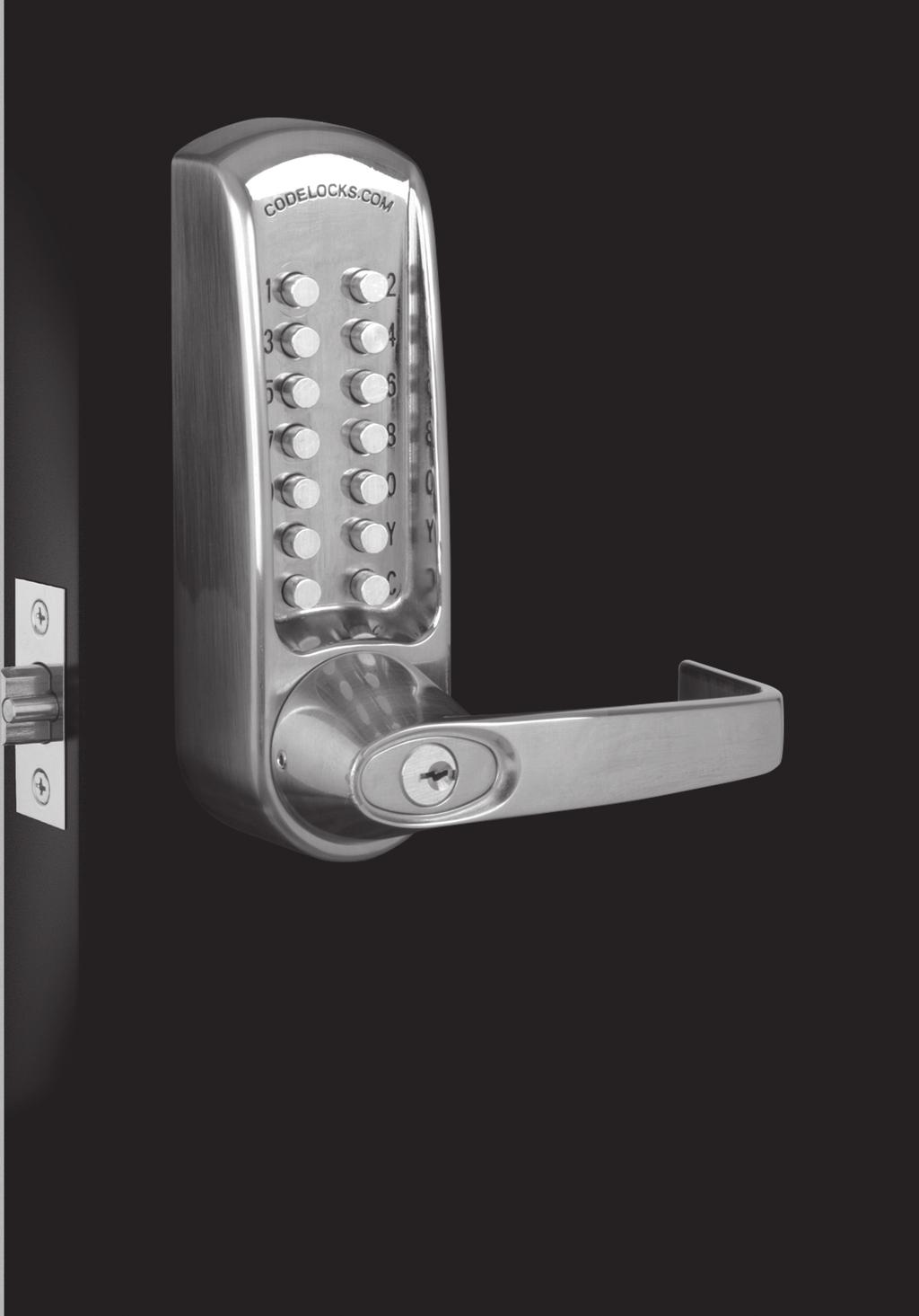
3 BOX CONTENTS CHECK OPERATION OF THE CODED FRONT PLATE On models CL605, CL615 and CL625 a free passage function is available. This is identified by a black dot on the bottom left hand Z button. In normal operation the code needs to be entered every time to retract the latch. To put the lock into free passage mode, first press the random factory set code, followed by the passage set button. The lock will now be in code free access mode. To put the lock to code access only press the passage set button once followed by the C button. See code change instructions on separate sheet 60mm/ 70mm (2 1 /4 ) (2 3 /4 ) The code may be entered in any sequence, ie 1370 may be entered as 0731 or any other sequence of those numbers. There are a total of 8,191 codes available on the CL600, CL610 and CL620 locks. There are 4,095 codes available on the CL605, CL615 and CL625 locks. 3
4 MODEL CL600/605 INSTALLATION INSTRUCTIONS The model CL600/605 is intended to replace the conventional door furniture fitted to an existing mortice latch, or an existing mortice lock which has both a spring latch and a deadbolt. The square follower should be 8mm ( 5 /16 ) square. Any lock and key mechanism is retained to operate the deadbolt. The CL600/605 will only operate the latchbolt and not the deadbolt. A mortice lock case should have holes for fixing bolts to pass through on either side of the square latch follower and sometimes, additionally, a hole below the follower. See figure 1 and confirm that your lockcase is compatible with the CL600/605 lock plates. ( 5 /16 ) IF YOUR LOCKCASE HAS A HOLE BELOW THE FOLLOWER (FIGURE 1 A ), PROCEED AS FOLLOWS: STEP 1 Hold the neoprene seal with the three fixing holes against the door, vertically, with the rectangular hole centrally over the follower. Mark the top and bottom holes on the door face, and repeat the procedure on the other side of the door. Remove the lock. At three points drill a10mm ( 3 /8 ) hole through the door. Drill from both sides for greater accuracy and to avoid splintering out of the door face. Check that the existing spindle hole is at least 18mm ( 3 /4 ) diameter. Refit the lock. IMPORTANT: When using CL600/CL605 front and back plates only, please test with your selected lock-case to ensure that the latch retracts fully from the code side without too much resistance. Some lock-cases have a heavily sprung latch follower designed for use with un-sprung lever furniture. This heavy springing can defeat the clutch on our locks. Please note the code chamber for mechanical locks requires the lever to be rotated at least 45 degrees to re-set the lock for the next code user. Please contact our Codelocks technical department if you are unsure. Codelocks Limited does not accept responsiblilty for products incorrectly specified. 4
5 MODEL CL600/605 INSTALLATION INSTRUCTIONS STEP 2 Take the BLUE or RED tipped spindle and fit to the code side according to the hand of your door (see diagram). Fit remaining spindle to inside - non code side. STEP 3 Cut three of the socket head bolts to the required length for your door. Approximate overall length should be door thickness plus 25mm (1 ), to allow about 10mm ( 3 /8 ) of threaded bolt to enter the outside plate. STEP 4 Remove plastic insert plug from frontplate. Apply the front and back plates, with the neoprene seals in position, against the door, over the protruding ends of the spindle. STEP 5 Fix the two plates together using the socket head bolts, starting with the top fixings. Ensure that the two plates are truly vertical and then tighten the bolts using the T shaped Allen key. Do not use excessive force. STEP 6 Fit the lever handles to suit the hand of the door. To change the hand of a lever handle, loosen the grub screw with the small Allen key, reverse the lever handle and fully tighten the grub screw. STEP 7 Ensure that the latchbolt retracts after the code is entered and the lever handle is depressed. Now check the operation of the inside lever handle. If there is any binding of the handles or latch then loosen the bolts slightly and reposition the plates until the correct position is found, and then re-tighten the bolts. IF YOUR LOCKCASE ONLY HAS HOLES ON EITHER SIDE OF THE FOLLOWER (FIGURE 1 B ), PROCEED AS FOLLOWS: STEP 1 Hold the neoprene seal against the door, perfectly vertically, with the rectangular hole centrally over the follower. Mark the top holes and the holes on either side of the follower if not already drilled, using adaptor plate as guide, then repeat the procedure on the other side of the door. Mark an extra hole on the inside of the door in line with the bottom fixing hole. Remove the lock. Drill the 4 x 10mm ( 3 /8 ) holes from both sides for greater accuracy, and to avoid splintering out of the door face. Check that the existing spindle hole is at least 18mm ( 3 /4 ). Drill the extra 12mm ( 1 /2 ) hole 5mm ( 3 /16 ) deep on the inside of the door to accept the fixing nut on the adaptor plate. Replace the lock. STEP 2 Take the BLUE or RED tipped spindle and fit to the code side according to the hand of your door (see diagram). 5
6 MODEL CL600/605 INSTALLATION INSTRUCTIONS STEP 2 (continued) Fit remaining spindle to inside - non code side. STEP 3 Take the adaptor kit, item 13 on the contents page. Cut the two M5 countersunk head bolts to length to suit the door thickness; i.e. door thickness plus a maximum of 10mm ( 3 /8 ) (no more than 5mm ( 3 /16 ) should enter the front plate). Hold the front plate, with the three hole neoprene seal, against the door over the protruding spindle. From the other side of the door, fix the adaptor plate to the front plate using the two M5 countersunk bolts. Before tightening up the fixings, make sure that the spindle hole is centrally positioned over the follower. Do not use excessive force. STEP 4 Cut two of the long socket head bolts to the required length for your door. Approximate overall length should be door thickness plus 25mm (1 ), to allow about 10mm ( 3 /8 ) of threaded bolt to enter the front plate. Place the neoprene gasket over the adaptor plate. Use the screw with the T shaped Allen key, to fix the back plate to the front plate through the TOP holes. Using the 20mm ( 3 /4 ) socket head bolt fix the back plate through the BOTTOM hole to the adaptor plate. Do not use excessive force. STEP 5 Check that the lever handles are correctly fitted for the hand of door. To change the hand of a lever handle, loosen the grub screw with the small Allen key, reverse the lever handle and fully tighten the grub screw. STEP 6 Before closing the door, enter the code and check that the latchbolt retracts when the lever handle is depressed. Now check the operation of the inside lever handle. If there is any binding of the handles or latch then loosen the top and bottom bolts and reposition the plates slightly until the correct position is found, and then re-tighten the bolts. 6
7 MODEL CL610/615 INSTALLATION INSTRUCTIONS The model CL610/615 has a tubular, deadlocking, mortice latch and may be used as a new installation on a door, or where an existing latch is to be replaced. When installing on a fire door, fire kit is required. Please refer to instructions on page 12 and 13. N.B. Ensure enough room for the latch support post Please align the template to suit the locks backset: 60mm (2 3 /8 ) standard or 70mm (2 3 /4 ). STEP 1 Lightly mark a height line on the edge and both faces of the door, and on the door jamb, to indicate the top of the lock when fitted. Crease the template (standard) along the dotted line, and tape it to the door with the top in line with the height line. Mark the 3 x 10mm ( 3 /8 ) and the 1 x 30mm (1 3 /16 ) holes. N.B. When fitting to a door with existing 54mm (2 1 /8 ) through hole, only top two 10mm ( 3 /8 ) holes need to be marked and drilled. Mark the centre of the door edge on the Centre Line of Latch. Remove the template and apply it to the other side of the door, aligning it accurately with the first Centre Line of Latch mark. Mark the 4 holes again. N.B. Space required above latch body for cam to rotate STEP 2 Keeping the drill level and square to the door, drill a 25mm (1 ) hole in centre of door edge, deep enough to accept the latch. STEP 3 Keeping the drill level and square to the door, drill the 10mm and 30mm ( 3 /8-1 3 /16 ) holes from both sides of the door to increase accuracy and to avoid splintering out the door face. STEP 4 Put the latch into the hole and, holding it square to the door edge, draw around the faceplate. Remove the latch and score the outline with a Stanley knife to avoid splitting when chiselling. Chisel a rebate to allow the latch to fit flush to the surface. STEP 5 Fix the latch with the wood screws, with the bevel towards the door frame. STEP 6 Fitting the strike plate. N.B. The plunger beside the latchbolt deadlocks it, to protect against manipulation or shimming. The strike plate must be accurately installed so that the plunger CANNOT enter the aperture when the door is closed, even if it is slammed shut. Position the strike plate on the door frame so that it lines up with the flat of the latchbolt, and NOT the plunger. Mark the positions of the fixing screws, and draw around the aperture of the strike plate. Chisel out the aperture 15mm ( 5 /8 ) deep to receive the latchbolt. Fix the strike plate to the surface of the frame using only the top fixing screw. Gently close the door and check that the latchbolt enters the aperture easily, and is held without too much play. When satisfied, draw around the outline of the strike plate, remove it and cut a rebate to enable the faceplate to lie flush with the surface. Re-fix the strike plate using both screws. 7
8 MODEL CL610/615 INSTALLATION INSTRUCTIONS STEP 7 Take the BLUE or RED tipped spindle and fit to the code side according to the hand of your door (see diagram). Fit remaining spindle to inside - non code side. STEP 8 Fit the latch support post into back of the code side front plate according to the hand of your door, A for a right hand door, or B for a left hand door (see diagram). STEP 9 Cut three of the socket head bolts to the required length for your door. Approximate overall length should be door thickness plus 25mm (1 ) to allow about 10mm ( 3 /8 ) of threaded bolt to enter the outside plate. STEP 10 Apply the front and back plates, with the neoprene seals in position, against the door, over the protruding ends of the spindle. STEP 11 Fix the two plates together using the socket head bolts, starting with the top fixing. Ensure that the two plates are truly vertical and then tighten the bolts using the T shaped Allen key. Do not use excessive force. STEP 12 Check that the lever handles are correctly fitted for the hand of door. To change the hand of a lever handle, loosen the grub screw with the small Allen key, reverse the lever handle and fully tighten the grub screw. STEP 13 Before closing the door, enter the code and ensure that the latchbolt will retract when the lever handle is depressed. Now check the operation of the inside lever handle. If there is any binding of the handles or latch then loosen the bolts and reposition the plates slightly until the correct position is found, and then re-tighten the bolts. 8
9 MODEL CL620/625 INSTALLATION INSTRUCTIONS The model CL620/625 has a mortice lock and may be used as a new installation on a door, or where an existing lock is to be replaced. IMPORTANT: The mortice lock provided (fig.2 - page 11) has features which are not found in most other locks and so it is recommended that you familiarise yourself with them as follows: A. When necessary the hand of the latchbolt can be changed by removing the three screws holding the faceplate to the lockcase, reverse the latchbolt, and tighten the screws back up, ensuring that the latchbolt is central. B. Put the key in the cylinder and insert it centrally into the lockcase. Fix it in position with the long bolt through the faceplate. It should now be possible to project and retract the deadbolt with the key, and also to retract the latchbolt. C.The square latchbolt follower is in 2 parts: the inside panic function follower will retract the latchbolt and also the deadbolt when it is projected. The effect of this is to ensure that it is not possible to accidentally lock someone in a room because the deadbolt is projected. The outside follower will always retract the latchbolt whenever the lever handle is depressed after a correct code is entered, but it will not retract the deadbolt. The hand of the panic function is determined as follows: the grub screws on the split follower facing the code side must be removed. This prevents the outside handle retracting the deadbolt. NEVER remove grub screws from both sides at the same time. All door locks should be installed with a degree of precision to ensure that all components are horizontally and vertically accurate in relation to each other, and in relation to the door. Do not install the lock where it will involve cutting into a joint between the door stile and a mid-rail. 9
10 MODEL CL620/625 INSTALLATION INSTRUCTIONS STEP 1 Lightly mark a height line on the edge and both faces of the door, and the door jamb, to indicate the top of the lock when fitted. Mark a line down the centre of the door edge, extending above the height line and 300mm (12 ) below it. STEP 2 Hold the template against the edge of the door with the top in line with the height line, and with the arrows in line with the Centre of Door Edge line. Mark the positions of the fixing holes, and the holes to be drilled for the mortice. STEP 3 Apply tape to the 16mm ( 5 /8 ) drill bit at 90mm (3 9 /16 ) from the tip to act as a depth guide when drilling the mortice holes. Ensure the drill is level and parallel to the door face and drill the holes as indicated on the template. Remove the remaining wood with a chisel to leave a clean mortice hole which accepts the lockcase without forcing. With the lock in the mortice make sure that the forend is parallel with the door edge and mark the outline of the forend plate. Cut the outline with a Stanley knife to avoid splitting out when chiselling. Chisel a rebate sufficient to accept the forend flush with the surface. STEP 4 Fold the template accurately along the dotted line and tape it to the door face with the top in line with the height line, and the fold on the door edge. Mark the centres of all the holes to be drilled. Remove the template and repeat the procedure on the other face of the door. STEP 5 Drill the holes from both sides of the door to improve accuracy and to avoid splintering out the door face. STEP 6 Install the lockcase in the door. STEP 7 Cut three of the socket head bolts to the required length for your door. Approximate overall length should be door thickness plus 25mm (1 ) to allow about 10mm ( 3 /8 ) of threaded bolt to enter the outside plate. STEP 8 Take the BLUE or RED tipped spindle and fit to the code side according to the hand of your door (see diagram). Fit remaining spindle to inside - non code side. STEP 9 Apply the front and back plates, with the neoprene seals in position, against the door, over the protruding ends of the spindle. STEP 10 Fix the two plates together using the socket head bolts, starting with the top fixings. Ensure that the two plates are truly vertical and then tighten the bolts using the T shaped Allen key. Do not use excessive force. 10
11 MODEL CL620/625 INSTALLATION INSTRUCTIONS STEP 11 Check that the lever handles are correctly fitted for the hand of door. To change the hand of a lever handle, loosen the grub screw with the small Allen key, reverse the lever handle and fully tighten the grub screw. STEP 12 Before closing the door, enter the code and check that the latchbolt will retract when the lever handle is depressed. Now check the operation of the inside lever handle. If there is any binding of the handles or the latch then loosen the bolts and reposition the plates slightly until the correct position is found, and then re-tighten the bolts. STEP 13 Fit the double Euro-profile cylinder and secure it with the long screw through the faceplate. Fit the cylinder escutcheons. STEP 14 Check that the deadbolt will project and retract by key, and that the key will also retract the latchbolt. Check that the inside lever handle WILL retract the deadbolt simultaneously with the latchbolt. Check that the outside lever handle WILL NOT retract the deadbolt. ( 7 /8 ) STEP 15 Mark a vertical line on the door jamb half the door thickness away from the door stop. This gives the centre line of the strike plate. Align the Strike Plate Template with the height line, with the arrow heads aligned with the centre line. Mark the fixing holes, and draw around the apertures for the latchbolt and the deadbolt. Chisel out the latch aperture to 12mm ( 1 /2 ) deep, and the deadbolt aperture to 22mm ( 7 /8 ) deep. FIGURE 2 CL620/625 lockcase Fix the strike plate with the top screw only and gently close the door. Ensure that the latchbolt enters its aperture easily and holds the door without too much play. When satisfied, draw around the final position of the strike plate, remove it, and cut a rebate to allow it to fit flush to the surface. Re-fix the strike with both screws. 11
12 FIRE KIT INSTALLATION INSTRUCTIONS Take time to be precise and finish the job quicker Installation holes must be drilled in exactly the correct positions and precisely at right angles to the door surface. Lock components must be vertically and horizontally accurate in relation to each other and to the door. WEDGE THE DOOR FIRMLY TO PREVENT MOVEMENT WHILST DRILLING AND CHISELLING Step 1 Lightly mark a height line on the edge and both faces of the door and on the door jamb, to indicate the top of the lock when fitted. Crease the template (fire) along the dotted lines and tape it to the door with the top in line with the height line. Mark the holes to be drilled. Mark the centre line of latch on to the door edge. Apply the template to the other side of the door precisely against the height line and the centre line of latch mark. Mark the holes to be drilled again. (See diagram A). Step 2 Keeping the drill level and straight, drill a 25mm (1 ) hole in the centre of the door edge to accept the latch. Put the latch into the hole and holding it square to the door edge, draw around the faceplate. Remove the latch. Starting with the top and bottom cuts, chisel a rebate to allow the latch faceplate to fit flush with the door edge. Step 3 Keeping the drill level and straight, drill the holes in the door face. Drill from both sides of the door to increase accuracy and to avoid damage to the other side when a drill goes right through. Step 4 Insert the fire cup into the 54mm (21/8 ) hole. N.B. open side of the fire cup to face code side with small bolt through hole at the bottom. Step 5 Reinsert the latch and fix the screws, with the bevel towards the door frame. (See diagram B). Step 6 Fit the spindles to the latch according to the hand of your door. Fit remaining spindle to inside - non code side. (see diagram below). Install the spindle washers (item 3) over the flat blade of both spindles. Use enough washers so they sit flush to the face of the door without bind when the Codelock is installed. Step 7 Fit the latch support post to hole adjacent to A for a left hand door, and adjacent to B for a right hand door. Diagram A Step 8 Screw the fixing posts (item 1 on page 13) into the front plate. Place the outer cover plate to the door with the inner cover plate (item 4) using the three fixing bolts (item 5). Step 9 Fix the front plate to the door with the inner cover plate (item 4) using the three fixing bolts (item 5). Fit the inside handle body to the inner cover plate using the three short fixing bolts (item 6). Step 10 Check that the lever handles are correctly fitted for the hand of door. To change the hand of a lever handle, loosen the grub screw with the small Allen key, reverse the lever handle and fully tighten the grub screw. Step 11 Before closing the door, enter the code and ensure that the latchbolt will retract when the lever handle is depressed. Now check the operation of the inside lever handle. If there is any binding of the handles or latch then loosen the bolts and reposition the plates slightly until the correct position is found, and then re-tighten the bolts. Diagram B 12
13 EXPLODED DIAGRAM SHOWING FIRE KIT Fire kit parts 1 Fixing Posts x 3 2 Outer Cover Plate 3 Spindle Washers x 8 4 Inner Cover Plate 5 Fixing Bolts x 3 6 Short Fixing Bolts x 3 7 Fire Latch 70mm (2 3 /4 ) 8 T Strike Plate 9 Fire Cup 13
14 BACK TO BACK AND PK VERSIONS Back to Back and PK versions - Models CL600/610/615BB & CL600/605PK A) The CL600 range is available in Back to Back versions where the code is on both sides of the door. To install the Back to Back versions: Follow instructions as for non back to back versions substituting the backplate and handle 2, with the coded plate with the through fixing holes. Please note that each side may be coded with the same or different codes. B) The CL600 range is also available to work with most single point panic pads or bars. In this format the front code plate only is supplied with suitable fixing to connect to most single point panic pads and latches. If in doubt ask. To install the PK versions: Step 1. The position of the CL600PK on the door is determined by the position of the panic device. Step 2. Mark the position of the spindle hole for the panic device on both sides of the door. Step 3. Place the CL600PK gasket against the door with the 20mm ( 3 /4 ) hole centred over the mark for spindle hole. Using the gasket as a template mark the 3 x 10mm ( 3 /8 ) holes for the through fixing bolts. Repeat on the other side of the door. Step 4. Drill the 1 x 20mm ( 3 /4 ) hole and the 3 x 10mm ( 3 /8 ) drilling holes, from both sides to avoid splintering out the face of the door. Step 5. Countersink the bottom fixing hole as necessary so that the fixing bolt lies flush with the door face, underneath the panic device. Step 6. Fit the lever handle to the CL600 front plate and tighten the grub screw in the handle. Enter the code of the CL600 front unit and check that the lever will turn fully see page 6. operation check. Step 7. Fit the CL600 front unit with the 3 fixing bolts. Insert the spindle with the flat blade into the CL600 front unit, ensuring that the blade is at the correct angle for the hand of door - see diagram page 8. Step 8. Install the panic device and make sure that the CL600 front unit will fully retract the latch or bolt. 14
15 DIMENSIONS 35-60mm (1⅜ - 2⅜ ) 185mm (7¼ ) 110mm (4 5 /16 ) Model CL600/605 For use with existing lock 58mm (2 5 /16 ) 73mm (2⅞ ) 87mm (3 7 /16 ) 60mm (2⅜ ) Model CL610/615 With tubular latchbolt 235mm (9⅝ ) 72mm (2⅞ ) 55mm (2 3 /16 ) 84mm (3 5 /16 ) Model CL620/625 With full Panic Function mortice lock & cylinder 15

16 II-CL CODELOCKS LTD UK Tel: +44 (0) Fax: +44 (0) Helpline, service & spares FREEPHONE CODELOCKS INC US Tel: Fax: Help:1.877.CODELOCK
Tools Required. * When installing on a fire door, please see instructions below. *
 CL615 Tubular Mortice Latch with Code Free option CL615 Tubular Mortice Latch with Code Free option Number relating to picture Item 1 Front Plate and handle * 2 Back Plate and handle * 3 Neoprene seals
P USHbutton 500 series
 Dimensions 35 60mm 178mm Model 500/505 For use with existing lock 1 6 2 7 3 8 4 9 5 0 1 6 2 7 3 8 4 9 5 0 Features ode Free Entry Mode by turning the slotted button 90 degrees after entering the code (models
Installation Instructions II-2/4/5K-0608
 Installation Instructions II-2/4/5K-0608 Box Contents Check the contents of the box are correct according to the model 2010 4010 4020 5010 5020 1 Front Plate 2/4000 - - 2 Front Plate 5000 - - - 3 Back
CL4500 Installation Instructions
 CL4500 Installation Instructions Box Contents Check the contents of the box are correct according to the model 4510 4520 1 Front Plate 2 Back Plate 3 Lever Handles 4 Gaskets 5 Sprung Spindle (x1) 6 Spring
Stage 2: Preparing the door (read in conjunction with Hole Drilling Options on back of Template).
.") There are three stages to fitting the CL100 mortise case: Stage 1: Marking out the position of the lock. Stage 2: Preparing the door by mortising and drilling holes. Stage 3: Fitting lock, door furniture,
There are three stages to fitting the CL100 mortise case: Stage 1: Marking out the position of the lock. Stage 2: Preparing the door by mortising and drilling holes. Stage 3: Fitting lock, door furniture,
Product Range.
 Product Range www.codelocks.com UK headquarters CODELOCKS LTD Castle Industrial Park, Kiln Road, Newbury, Berks RG14 2EZ UNITED KINGDOM Tel + 44 (0) 1635 239645 Fax + 44 (0) 1635 239644 sales@codelocks.co.uk
Installing Your Electronic Deadbolt
 Ultra Security Plus Electronic Deadbolt Installation Instructions http://www.hberger.com/video-gallery/electronic-deadbolt New Installation Lock Location Preparation (Skip this section if you door has
Product Range.
 Product Range www.codelocks.com UK headquarters At Codelocks, we are dedicated to giving our customers control and convenience. Our comprehensive range of mechanical and electronic locks provide solutions
CRCODE-202. Mechanical Lock. Instruction and Programming Manual. Before Installing:
 CRCODE-202 Mechanical Lock Instruction and Programming Manual Before Installing: 1. Please read the instructions carefully to prevent missing important steps. *Note: Improper installations may result in
Hardware Installation. Do this first:
 1 Do this first: Hardware Installation Need some help? Here s what you ll need: 4 AA Batteries Phillips screwdriver Visit us online. support.remotelock.com We re here to help. 1 (877) 254 5625 support@remotelock.com
Door Hardware Installation Instructions. For Assistance Call:
 For Assistance Call: Door Hardware Installation Instructions Single Cylinder NOTE: s fit doors 1-3/4 to 2-1/4 thick. For thicker doors, please call customer service. Carefully unpackage all components
INSTALLATION INSTRUCTIONS FOR INSTALLING T-SERIES EXTRA HEAVY DUTY LEVER LOCKSET
 HIGH EDGE 2 1/4"(57mm) 03079400070 INSTALLATION INSTRUCTIONS FOR INSTALLING T-SERIES EXTRA HEAVY DUTY LEVER LOCKSET IMPORTANT: THIS LOCK IS NON-HANDED. LOCK IS FACTORY PACKED PREADJUSTED FOR 1³ ₄" (45mm)
33/3547A. Special tools needed: #10-24 tap Drill bits: #25, 5/16, 13/32, 1/2
 911404-00 Concealed Vertical Rod Exit Device 33/3547A Installation Instructions Devices covered by these instructions: 33/3547A and 33/3548A Concealed Vertical Rod Exit Device 33/3547A-F and 33/3548A-F
Installation Instructions for Trilock Omni BB Twin Pull Handle Version - Suits 35mm to 45mm door thickness
 Installation Instructions for Trilock Omni BB Twin Pull Handle Version - Suits 35mm to 45mm door thickness Step 1. Fold template where indicated. Position template on door edge at desired lock / latch
Available in two PVD finishes
 PVD, low maintenance, weather resistant finish Available in 5 functions Easy to fit Hexagonal bevelled handle and lock case Tumbler alignment for easy code change Key bypass option may be specified on
INFORMATION. PARTS LIST Please make sure you have received the following parts: ACCESSORIES PACK 2 Latch (60m m standard)
") PARTS LIST, INSTALLATIN AND GENERAL INFRMATIN PARTS LIST Please make sure you have received the following parts: () 1 utside lock mechanism ( 2) Inside lock mechanism () 3 Accessories in 4 packs ACCESSRIES
PARTS LIST, INSTALLATIN AND GENERAL INFRMATIN PARTS LIST Please make sure you have received the following parts: () 1 utside lock mechanism ( 2) Inside lock mechanism () 3 Accessories in 4 packs ACCESSRIES
ED1300/1300F SERIES CONCEALED VERTICAL ROD DEVICE INSTALLATION INSTRUCTIONS
 ED1300/1300F SERIES CONCEALED VERTICAL ROD DEVICE INSTALLATION INSTRUCTIONS Ver.2 1300 SERIES CONCEALED VERTICAL ROD DEVICE Top Strike Latch Screws Strike Screws Release Plunger Top Latch Plunger Screws
Replacement PVCu Door Lock
 Replacement PVCu Door Lock Universal replacement lock designed to fit most PVCu doors Pack contents Lock Fixing tab Keep Before you begin Please read these instructions carefully Following the steps in
33/3527A. Devices covered by these instructions: 33/3527A-F (Fire) Surface Vertical Rod Exit Device
 Surface Vertical Rod Exit Device") *911403-00* 911403-00 Surface Vertical Rod Exit Device 33/3527A Installation Instructions Devices covered by these instructions: 33/3527A Surface Vertical Rod Exit Device 33/3527A-F (Fire) Surface Vertical
*911403-00* 911403-00 Surface Vertical Rod Exit Device 33/3527A Installation Instructions Devices covered by these instructions: 33/3527A Surface Vertical Rod Exit Device 33/3527A-F (Fire) Surface Vertical
Congratulations! You are now on your way to enriching your life with!
 C) Using the base point as your reference, measure up 8-1/32 and mark a horizontal line. Measure in from the edge of the door the distance of your backset and mark where the two lines cross. This will
Congratulations! You are now on your way to enriching your life with! Figure #5. Step 5 Install the Dummy Deadbolt. Step 3 Drill the Door
 C) Using the base point as your reference, measure up 8-1/32 and mark a horizontal line. Measure in from the edge of the door the distance of your backset and mark where the two lines cross. This will
ASSA ABLOY, the global leader in door opening solutions. Need-to-Know Guide
 Need-to-Know Guide ASSA ABLOY, the global leader in door opening solutions HELPING YOU TO MAKE THE RIGHT CHOICE. WE ARE UNION. Mortice Locks Panic and Emergency Exit Devices Door Closers Scan here to find
MORTISE LOCKS LA1Tx7 //DATASHEET
 //DATASHEET SATO ocks AElement Access control requires a good, reliable door locking system. SATO offers a wide range of mortise locks in order to ensure that the door is correctly locked. Whether you
Installation Instructions
 Supafold Slide Aside System Three Fold Room Divider Installation Instructions Distinctive Doors Ltd Supafold Slide Aside Internal Folding System IMPORTANT: Before proceeding with the installation, and
Door Hardware Installation Instructions. Version A No Interior on an Un-prepped Door Step 1 Select the Position of the Handleset
 For Assistance Call: 1-800-522-7336 8 am - 5 pm, Monday - Friday, MST or visit our Website at: www.grandeur-nw.com Door Hardware Installation Instructions Dummy Handleset Optional Rosette (Round) Interior
* * 98/9950WDC. Fire-Rated Devices include these. additional components. 1-Point Latch (LBL)
") *24739468* 24739468 98/9950WDC Installation Instructions 1-Point Latch (LBL) Fire-Rated Devices include these additional components Metal Edge Wrap required for 60 and 90-minute applications 2-Point Latch
*24739468* 24739468 98/9950WDC Installation Instructions 1-Point Latch (LBL) Fire-Rated Devices include these additional components Metal Edge Wrap required for 60 and 90-minute applications 2-Point Latch
Fig. 2 DORMA-Glas Stand/Issue 02/03 Seite/Page 1/7
 FSW Installation instructions Track rail 75 x 72 mm 1. Ceiling substructure and installation of the track rail (Fig. 1): The track rail must be bolted over its entire length (including the stacking track
Installation Instructions
 VON DUPRIN Installation Instructions 98/9947WDC Concealed Vertical Rod Exit Device Wood Door Applications Devices covered by these instructions: 98/9947WDC Concealed Vertical Rod Device 98/9947WDC-F (Fire)
INSTALLATION INSTRUCTIONS REPLACING EXISTING DEADBOLT ASSEMBLY
 INSTALLATION INSTRUCTIONS REPLACING EXISTING DEADBOLT ASSEMBLY A B C L M N D E F G O P Q H I J Tools provided in Amesbury installation kit: (A) door router fixture, (B) doorframe router fixture, (C) ½
Installation Guide. Bi-fold Doors
 Installation Guide Bi-fold Doors Installation Guide Components box 1. 6. 2. 3. 7. 5. 4. 8. Contents 1. Fixing plugs 2. Wedge gasket 3. Bottom trolley 4. Top trolley 5. Magnetic keep (x 2 if door height
Installation Instructions for 45HW & 47HW Electrified Mortise Locks
 Installation Instructions for 45HW & 47HW Electrified Mortise Locks Contents These installation instructions describe how to install your 45HW & 47HW Electrified Mortise Lock. Topics covered include: Finishing
Entry Mortise Handleset
 1. Pencil 2. No. 2 and No. 3 Phillips Head Screwdrivers 3. No. 1 and No. 2 Slotted Screw Drivers 4. 1/8" Allen Head Wrench 5. 3/4" Wood Chisel or Corner Chisel 6. Measuring Device 7. Lock Mortising Tool
L2C25 Deadlocking mortice nightlatch. L2C26 Mortice escape sashlock. 2C27 Mortice bathroom lock 3 M F 2 B B M F 2 B C 2 0
 L2C25 Deadlocking mortice nightlatch Cylinder key operation from the outside of the door and handle operation from inside Latchbolt is automatically locked by the anti-thrust bolt - stainless steel latch
For installation assistance, contact SARGENT at DOORS SHOWN HERE SWING IN FOR ILLUSTRATION PURPOSES ONLY.
 SARGENT Installation Instructions for LP8600 x LR8600 & 12-LP8600 x 12-LR8600 Series Low Profile Panic and Fire Exit Devices on Double Egress & Double Doors or LS8600 & 12-LS8600 Low Profile Exit Device
Installation Instructions For The 8850FL Series Mortise eboss
 Installation Instructions For The 8850FL Series Mortise eboss Electronic Battery Operated Security Solution FEATURES Battery Operated (Hardwire Capable) Motorized Grade 1 Mortise Lock 94 User Code Capacity
Your combination is and is not recorded at the factory. This number can be found on the combination slides if required.
 3778 South Kalamath Street, Englewood, CO 80110 Phone (303) 762-7373 Fax (303) 484-4070 www.presomatic.com office@presomatic.com Installation Instructions for Deadlatch Models 8200 8200A Congratulations
OVERVIEW. Mounting Post (2 places) Cylinder Cam. Handing Pin
 Cylinder Cam. Handing Pin") DEVICES COVERED IN THIS DOCUMENT: 46CE Cylinder Escutcheon Key locks and 46DT Dummy Trim Pull when dogged unlocks lever 46BE Blank Escutcheon Always operable 46NL Night Latch Key retracts latchbolt 46NK
DEVICES COVERED IN THIS DOCUMENT: 46CE Cylinder Escutcheon Key locks and 46DT Dummy Trim Pull when dogged unlocks lever 46BE Blank Escutcheon Always operable 46NL Night Latch Key retracts latchbolt 46NK
Installation Instructions for 45H & 47H Mortise Locks
 Installation Instructions for 45H & 47H Mortise Locks Contents These installation instructions describe how to install your 45H & 47H Mortise Lock. Topics covered include: Finishing the preparation...
*D-1030* 1 PARTS CHECK 8 REVERSING INSTRUCTIONS F-XX-C & XX-C D Customer Service. Installation Instructions. Exit Devices
 *D-1030* D-1030 F-XX-C & XX-C Exit Devices Installation Instructions 8 REVERSING INSTRUCTIONS TO REVERSE THE HANDING OF A (F)XX-C DEVICE NOTE: TO REVERSE TRIM, REFER TO SEPARATE INSTALLATION SHEETS. 1
Installation Instructions for Deadbolt Models OP 8102LT
 3778 South Kalamath Street, Englewood, CO 80110 Phone (303) 762-7373 Fax (303) 484-4070 www.presomatic.com office@presomatic.com Installation Instructions for Deadbolt Models 8101 8101OP 8102LT Congratulations
Travel Trailer Latch With Dead Bolt Trailer Latch With Dead Bolt. U.S. Patent No. 5,927,773
 60-250 Travel Trailer Latch With Dead Bolt 60-251 Trailer Latch With Dead Bolt Service Manual (Installation and Troubleshooting) U.S. Patent No. 5,927,773 CONTENTS 1. BASIC COMPONENTS 2. INSTALLATION OF
MULTIPOINT LOCKS. An ASSA ABLOY Group brand ASSA ABLOY
 MULTIPOINT LOCKS An ASSA ABLOY Group brand ASSA ABLOY JL22180 High Security Centre Unit JL22180 High Security Centre Unit Ideal for aluminium and PVCu doors. Operation Single throw deadbolt containing
Shepherd 210A Fingerprint Door Lock Installation Manual V1.1
 Shepherd 210A Fingerprint Door Lock Installation Manual V1.1 Hongda USA Inc. 2505 Technology Dr. #2-6A, Hayward, CA 94545, USA Phone: (510) 887-5682 Fax: (510) 372-0487 Email: info@hongdausa.com Website:
Atrium Patio Door Field Service Manual
 Atrium Patio Door Field Service Manual December 2005 Table of contents Service Agreement Pg 2 Release Agreement Pg 5 Inspection form Pg 6 Warranty Pg 8 Replacing swing panel Pg 12 Replacing sliding panel
Installation Instructions ENGLISH
 Installation Instructions ENGLISH Interior Latchset PRIVACY (Bed & Bath) PASSAGE (Hall & Closet) PK.5400 Congratulations! With your purchase of this Interior Latchset, you re among a group of discerning
Contract range of locks and latches
 Contract range of locks and latches E N 1 2 2 0 9-2 0 0 3 Tested The Gridlock Security Products contract range of locks and latches has all been successfully tested at Warrington Certification Ltd to meet
BARN DOOR HARDWARE KIT
 INSTALLATION GUIDE Main Components x1 Rail x5 Wall Spacer x2 Anti-jump Block x2 Bent Strap x1 Right Stopper x1 Left Stopper x5 5/16 (8mm x 60mm) Carriage Bolt x5 5/16 (8mm x25mm) Anchor x5 5/16 (8mm x
Safety glasses Measuring tape Level Pencil Power drill Center punch Phillips screw driver Saw horse
 EX76 Concealed Vertical Rod Exit Device Preparation Guide and Installation Instructions Box Contents EX76 Concealed Vertical Rod Exit Device Back Bar Active Push Bar Filler Plate Door Kit with Templates
EXIT DEVICE OPERATION FIRE DOOR LABELS, STRIKES AND FRAME SCREWS FOR INFORMATION CALL OR VISIT RITEDOOR.COM
 RECORD & LABELS WHAT THIS OWNER'S CAN DO FOR YOU It explains exactly how The Rite Door operates. It explains periodic maintenance requirements necessary to assure reliable operation. It explains simple
98/9927. Devices covered by these instructions: Surface Vertical Rod Exit Device
 911375-00 Surface Vertical Rod Exit Device 98/9927 Installation Instructions Devices covered by these instructions: 98/9927 Surface Vertical Rod Exit Device 98/9927-F (Fire) Surface Vertical Rod Exit Device
Installation Instructions
 for s TOC Table of Contents 1 Mortise Lock Handing Instructions.... 2 2 3 4 5 Mortise Lock Door Preparation & Installation... 3 HSS Trim Installation.... 5 Knob x Knob...6 Lever x Knob....7 Turn-Piece
UNION Aptus 2 Contract Mortice Lock Range. ASSA ABLOY, the global leader in door opening solutions
 UNION Aptus 2 Contract Mortice Lock Range ASSA ABLOY, the global leader in door opening solutions Introducing the new Aptus 2 contract mortice lock range from UNION UNION s new modular range of 72mm centre,
PROFESSIONAL LOFT LADDER
 PROFESSIONAL LOFT LADDER TWIST CATCH ASSEMBLY A4 A3 A2 A1 A7 A6 A5 A Installation and Operating Instructions Read Carefully Before Installation Please check you have all components listed (tick Boxes)
INSTALLATION INSTRUCTIONS CRL JACKSON
 INSTALLATION INSTRUCTIONS CRL JACKSON 3185 MID-PANEL CONCEALED VERTICAL ROD PANIC EXIT DEVICE crlaurence.com Phone: (800) 421-6144 Fax: (866) 921-0531 crlaurence.com usalum.com crl-arch.com 11M0252 ORDER
EASY STOW/HIDEAWAY LOFT LADDER
 EASY STOW/HIDEAWAY LOFT LADDER TWIST CATCH ASSEMBLY A4 A3 A2 A1 A7 A6 A5 A Installation and Operating Instructions Read Carefully Before Installation Please check you have all components listed (tick Boxes)
No. 059FL. No. 251FL. No. 260FL. No. 305RE. Etruscan Bronze. Florentine Brass. Siena Brass (D) All designs available in these finishes.
 All designs available in these finishes.") SINCE 1964 No. 059FL No. 251FL No. 260FL No. 305RE 2 Etruscan Bronze (ETR) Florentine Brass (D) Siena Brass (BAS) Venetian Nickel (BPS) All designs available in these finishes. No. 309RE No. 331FL No.
SINCE 1964 No. 059FL No. 251FL No. 260FL No. 305RE 2 Etruscan Bronze (ETR) Florentine Brass (D) Siena Brass (BAS) Venetian Nickel (BPS) All designs available in these finishes. No. 309RE No. 331FL No.
Custom Wood Frame Overlay for Glass Doors Installation Instructions
 MARVEL CUSTOM WOOD FRAME OVERLAY FOR GLASS DOORS Custom Wood Frame Overlay for Glass Doors Installation Instructions Wine Cellars 6SWC 6SWCE 61WC 61WCM 66SWC (2 required) 66SWCE (2 required) Beverage Centers
MORTISE LOCK INSTALLATION INSTRUCTIONS
 MORTISE LOCK INSTALLATION INSTRUCTIONS INSPIRE TM ROSELESS DESIGNER TRIM FM 340 Rev. 10/18 TABLE OF CONTENTS: DOOR PREPARATION 1 ML2000 LOCK HANDING 2 FULL WORKING TRIM (STD) 3 HALF WORKING TRIM (M30)
Passage Mortise Lock Set Lever to Lever
 Passage Mortise Lock Set Lever to Lever 1 Lever 2 Escutcheon 3 Mortise Lock 4 Scalp 5 Mortise Lock Strike 6 Mortise Lock Dust Box 7 Spindle 8 Spindle Spring 9 Spindle Retainer 2 1 9 8 7 9 7 8 3 1 2 4 5
Rugged Ridge Body Armor Guard Kit, 5 Pieces, Black (07-Current JK 4-door)
") Rugged Ridge Body Armor Guard Kit, 5 Pieces, Black (07-Current JK 4-door) Installation Time: 60 Minutes Tools Required: Notes: Phillips head screwdriver 3/8 socket or Flat head screwdriver 1/2 socket 7
Rugged Ridge Body Armor Guard Kit, 5 Pieces, Black (07-Current JK 4-door) Installation Time: 60 Minutes Tools Required: Notes: Phillips head screwdriver 3/8 socket or Flat head screwdriver 1/2 socket 7
INSTALLATION INSTRUCTIONS Z7800 SERIES MORTISE LOCK
 801 Avenida Acaso, Camarillo, Ca. 93012 (805) 4940622 www.sdcsecurity.com Email: service@sdcsecurity.com A. Door Preparation: INSTALLATION INSTRUCTIONS Z7800 SERIES MORTISE LOCK 1. Measure desired height
installation instructions
 installation instructions Easi-Plan WC Frame 820mm with Dual Flush Cistern ref: EPWC-05-1005 Easi-Plan WC Frame 980mm with Dual Flush Cistern ref: EPWC-05-1505 EASI-PLAN installation instructions Parts
M4 Foot Operated Underpinner Instruction Manual
 M4 Foot Operated Underpinner Instruction Manual M4 Walker Rd, Bardon Hill, Coalville, Leicestershire LE67 1TU, England Tel. +44 (0)130 1692, Fax +44 (0)130 16929 e mail sales@framerscorner.co.uk M4 Underpinner
Arriva. Concealed frame doorsets. Installation instructions
 Arriva Concealed frame doorsets 1 2 Installation instructions 3 Thank you for choosing Arriva To ensure the installation process is simple and efficient we recommended you read this guide in full before
CONTENTS TOOL LIST U P S I D E I N N O V A T I O N S, L L C RAMP AND STEP SYSTEM ASSEMBLY INSTRUCTIONS. Revised: June 2013
 U P S I D E I N N O V A T I O N S, L L C RAMP AND STEP SYSTEM ASSEMBLY INSTRUCTIONS TOOL LIST Required Tools: - Reciprocating Saw with Metal Cutting Blade - Drill - 7/16 Drill Bit for Metal Drilling -
Deauville Installation Guide
 vjul16 (for 17 or 24 mm Surface Wall Profiles) DO NOT ASSEMBLE WITHOUT FULLY READING THESE INSTRUCTIONS Page 2 Thank you for purchasing this Deauville shower enclosure. Please study these instructions
ED5800 (A) Series. Installation Instructions. Concealed Vertical Rod. Exit Device WARNING
 Series. Installation Instructions. Concealed Vertical Rod. Exit Device WARNING") Strike Shim (2) Supplied Strike Plate (3) 10-24 x 3/4" PFHMS (6) 10-24 x 1/2" PFHMS Top Latch TopTube Concealed Vertical Rod Exit Device Important: For use with metal doors only. Device is packed ready
Strike Shim (2) Supplied Strike Plate (3) 10-24 x 3/4" PFHMS (6) 10-24 x 1/2" PFHMS Top Latch TopTube Concealed Vertical Rod Exit Device Important: For use with metal doors only. Device is packed ready
CONCEALED VERTICAL ROD PANIC EXIT DEVICE
 INSTALLATION INSTRUCTIONS CRL JACKSON 1085-1085P CONCEALED VERTICAL ROD PANIC EXIT DEVICE crlaurence.com Phone: (800) 421-6144 Fax: (866) 921-0531 crlaurence.com usalum.com crl-arch.com 11M0236 ORDER OF
INSTRUCTIONS TO INSTALL THE ORA XL MIRROR TO THE NISSAN PATROL GU SERIES
 Tools Long flat screw driver and a small flat screw driver Phillips head screw driver 10mm Socket Container to hold bolts, screws and loose items. Installation INSTRUCTIONS TO INSTALL THE ORA XL MIRROR
Assembly guide. Before you start...check the pack and make sure all the components and fixings are included see. Tools required (Not Supplied)
") M FITT-054 Issue - Issue Assembly guide Soft close 800 LH Pull & Swing Corner Unit Component parts Tools required (Not Supplied) B S O T Spirit level Cross Head Screwdriver Tape measure E&F J P* Allen
M FITT-054 Issue - Issue Assembly guide Soft close 800 LH Pull & Swing Corner Unit Component parts Tools required (Not Supplied) B S O T Spirit level Cross Head Screwdriver Tape measure E&F J P* Allen
Installers guide Deadbolt 02.
 Installers guide Deadbolt 02. version 0.7.1 Specifications Model igloohome Smart Deadbolt 02 Material Zinc Alloy Current Rating (Standby) ~30uA Current Rating (Active) ~200mA Batteries 4 x AA Alkaline
INSTALLATION GUIDE SLIMLINE ROOF LANTERN 4 PANE CONFIGURATION
 INSTALLATION GUIDE SLIMLINE ROOF LANTERN 4 PANE CONFIGURATION SLIMLINE STEP-BY-STEP INSTALLATION GUIDE Thank you for choosing Roof Maker, we hope you are delighted with your new rooflight. Our roof lanterns
Entry Mortise Lock Set Lever to Lever
 Entry Mortise Lock Set Lever to Lever 1 Lever 2 Escutcheon 3 Turn Piece 4 Mortise Lock 5 Scalp 6 Mortise Lock Strike 7 Mortise Lock Dust Box 8 Mortise Cylinder 9 Cylinder Swing Cover 10 Spindle 11 Spindle
Rim-Lock Door Set Installation Instructions
 Rim-Lock Door Set Installation Instructions Let s get started Check Your Parts List Two Doorknobs with Set Screws B. Doorknob Spindle C. Rim Lock with Mounting Screws D. Keeper with Mounting Screws E.
PMR ELECTRONIC LOCK USER GUIDE
 封底 封面 148.5 x 210(mm) www.ezset.com.tw PMR ELECTRONIC LOCK USER GUIDE 封面裡 Parts Introduction Do not use an electric screwdriver when installing the product! Installation Procedures 1. Draw horizontal lines
Portofino Case2 Installation Guide
 Portofino Case2 Installation Guide vjun16 (for 17 or 24 mm Surface Wall Profile) DO NOT ASSEMBLE WITHOUT FULLY READING THESE INSTRUCTIONS Page 2 Thank you for purchasing this Portofino Case 2 shower enclosure.
B A T H R O O M G L A S S
 mistley B A T H R O O M G L A S S vaug16 Page 2 Thank you for purchasing this Trinity shower screen. Please study these instructions carefully before assembly and installation and check all supplied parts
CM5100 COMPUTER MANAGED CYLINDRICAL LOCK HARD-WIRED (FSE/FSA) INSTALLATION MANUAL
 INSTALLATION MANUAL") The 5100 series lock is a stand-alone, microprocessor controlled, electromechanical locking system. The 5100 employs a heavy-duty mechanical design which is easy to install and highly reliable. The FSE
The 5100 series lock is a stand-alone, microprocessor controlled, electromechanical locking system. The 5100 employs a heavy-duty mechanical design which is easy to install and highly reliable. The FSE
Portofino Installation Guide
 vjul16 (for 17 or 24 mm Surface Wall Profiles) DO NOT ASSEMBLE WITHOUT FULLY READING THESE INSTRUCTIONS Page 2 Thank you for purchasing this Portofino shower enclosure. Please study these instructions
Side Light Frame Pack Assembly Instructions
 Please read this complete set of assembly instructions before starting the installation and only when you understand the construction method start to follow the step by step guide. IDENTIFY THE PACK CONTENTS
Frameless Inline Door QCI5250
 INSTALLATION INSTRUCTIONS Frameless Inline Door QCI5250 FRAMELESS PANEL / DOOR / PANEL QCI0249 REV. 3 Page 1 Certified 10/12/12 Parts List with pivot hinges *Quantities may vary. QCI0249 REV. 3 Page 2
7130(F) Series Mortise Exit Devices Installation Instructions
 Series Mortise Exit Devices Installation Instructions") 7130(F) Series Mortise Exit Devices Installation Instructions Outside Trim Device is packed ready for any Yale 650F or 660F Series Trim. End Clamp (3) 8-32 x 5/16" PUFHMS End Cap (2) 1/4-20 x 1" PPHMS
7130(F) Series Mortise Exit Devices Installation Instructions Outside Trim Device is packed ready for any Yale 650F or 660F Series Trim. End Clamp (3) 8-32 x 5/16" PUFHMS End Cap (2) 1/4-20 x 1" PPHMS
x2 1/4 (6mm) Floor Anchor
 Floor Anchor") INSTALLATION GUIDE Main Components x1 Rail x5 Wall Spacer x2 Anti-jump Block x2 Straight Strap x1 Right Stopper x1 Left Stopper x5 5/16 (8mm x 60mm) Carriage Bolt x5 5/16 (8mm x25mm) Anchor x5 5/16 (8mm
INSTALLATION GUIDE Main Components x1 Rail x5 Wall Spacer x2 Anti-jump Block x2 Straight Strap x1 Right Stopper x1 Left Stopper x5 5/16 (8mm x 60mm) Carriage Bolt x5 5/16 (8mm x25mm) Anchor x5 5/16 (8mm
CONCEALED ROD CRASH BAR PR-7085 SERIES EXIT DEVICE ASSEMBLY DETAILS PR mm. 10mm. Lock cylinder. 10mm. Cross bar length (see note #8) Dogging
 Dogging") Floor line TITLE ASSEMLY DETAILS PR-7085 4:02 Hinge stile (inside) Lock stile (inside) Lock stile (outside) Drill 5mm (.20) and tap 1/4-20 (2) Drill 7mm (.266) holes (2) 9mm 12mm See note #6 160mm 9.5mm
Floor line TITLE ASSEMLY DETAILS PR-7085 4:02 Hinge stile (inside) Lock stile (inside) Lock stile (outside) Drill 5mm (.20) and tap 1/4-20 (2) Drill 7mm (.266) holes (2) 9mm 12mm See note #6 160mm 9.5mm
Installation Instruction
 Tools Needed for Assembly Stud finder (for wood stud wall) Pencil Mark Electric drill Wood Stud Wall Installation Step 1. Locate the Wood Studs Installation Instruction Drill bit (for wood stud wall) Masonry
Side Light Frame Pack Assembly Instructions
 Side Light Frame Pack Assembly Instructions Please read this complete set of assembly instructions before starting the installation and only when you understand the construction method start to follow
2&3 SECTION LOFT LADDER
 2&3 SECTION LOFT LADDER TWIST CATCH ASSEMBLY A4 A2 A1 A3 A7 A6 A5 Images feature the 3 section loft ladder, but the same instructions apply to both 2 & 3 section ladders Installation and Operating Instructions
Product data sheet R106FS POWERMATIC FREE SWING DOOR CLOSER
 Product data sheet R106FS POWERMATIC FREE SWING DOOR CLOSER The Powermatic Free Swing Door Closer, once installed with a power supply, allows the door to operate normally and function the same as a door
XL JOINERY LTD LA PORTE VISTA MODULAR 3 ASSEMBLY INSTRUCTIONS
 XL JOINERY LTD LA PORTE VISTA MODULAR 3 2090mm High x 4687mm Wide ASSEMBLY INSTRUCTIONS READ AND UNDERSTAND THESE INSTRUCTIONS FULLY PRIOR TO STARTING INSTALLATION. IT IS STRONGLY RECOMMENDED THAT A COMPETENT
LKM7004 Increased Safety, Increased Security, Increased Functionality.
 LKM7004 Increased Safety, Increased Security, Increased Functionality. Installation Instructions In A Single Motion, We ll Change The Way You Think About Security. US Patent #7,007,524,B2 1 LKM7004 Inside
INSTALLATION INSTRUCTIONS CRL JACKSON
 INSTALLATION INSTRUCTIONS CRL JACKSON 2085 CONCEALED VERTICAL ROD PANIC EXIT DEVICE crlaurence.com Phone: (800) 421-6144 Fax: (866) 921-0531 crlaurence.com usalum.com crl-arch.com 11M0250 ORDER OF ASSEMBLY
Allora ALCOVE ENCLOSURE INSTALLATION BEFORE INSTALLATION CHECK THAT YOUR ALLORA SHOWER ENCLOSURE SYSTEM IS UNDAMAGED
 Allora ALCOVE ENCLOSURE INSTALLATION BEFORE INSTALLATION CHECK THAT YOUR ALLORA SHOWER ENCLOSURE SYSTEM IS UNDAMAGED ALCOVE SHOWER Your shower can be installed to open Left hand or Right hand by rotating
DOOR TECHNOLOGY ORDER CATALOG SECTION SECURY Automatic Door Lock & Gripset Handle
 DOOR TECHNOLOGY ORDER CATALOG SECTION 03.3 SECURY Automatic Door Lock & Gripset Handle Table of Contents 03.3 SECURY Automatic Door Lock & Gripset Handle SECURY Automatic Door Lock...03.3.5 Automatic
BS 5 lever mortice locks
 BS 5 lever mortice locks UNION Architectural Hardware is proud to announce the new British Standard 5 lever mortice lock - UNION StrongBOLT UNION StrongBOLT features radius inner forends for ease of first
HEAVY DUTY GASKET CUTTER
 HEAVY DUTY GASKET CUTTER GUIDE TO PERFECT GASKETS CUTTING GASKETS 1 TO 13 IN DIAMETER: 1. Lay out gasket outer diameter (OD), inner diameter (ID) and bolt holes on template or gasket material. See section
PRODUCT: LOKI INSTALLATION INSTRUCTIONS. Product is covered by U.S. patents. For more information visit
 R INSTALLATION INSTRUCTIONS PRODUCT: LOKI CONFIGURATION: SINGLE DOOR MOUNT: GLASS MOUNT Product is covered by U.S. patents. For more information visit www.krownlab.com . TOOLS + MATERIALS REQUIRED TOOLS
2&3 SECTION LOFT LADDER Images feature the 3 section loft ladder, but the same instructions apply to both 2& 3 section ladders
 TWIST CATCH ASSEMBLY A4 A2 A1 A3 A7 A6 A5 2&3 SECTION LOFT LADDER Images feature the 3 section loft ladder, but the same instructions apply to both 2& 3 section ladders A Installation and Operating Instructions
GROWING BETTER THROUGH DESIGN. 6ft Lean-To LEAN-TO. Assembly Instructions 04/02
 GROWING BETTER THROUGH DESIGN 6ft Lean-To LEAN-TO Assembly Instructions 04/02 6ft Lean-To Greenhouse Base Plan Introduction/Tools/Contents / / Contents This is a copy of our Lean-To greenhouse base plan.
1530(F) Mortise Exit Devices Installation Instructions
 Mortise Exit Devices Installation Instructions") 1530(F) Mortise Exit Devices Installation Instructions Singe Doors or Pairs (2) 12-12-24 PFHUM/WS 798 Universal Strike Standard Device Package Devices are packed ready for application reinforced metal
1530(F) Mortise Exit Devices Installation Instructions Singe Doors or Pairs (2) 12-12-24 PFHUM/WS 798 Universal Strike Standard Device Package Devices are packed ready for application reinforced metal
Acoustical Surfaces, Inc.
 RECEIVING 1. Immediately inspect shipment for damage during transit, for example: damage caused by fork lifts, stacking, water stains etc. and disclose to delivery driver prior to signing for receipt.