Modular transfer system. PDF- Catalog Modular Transfer System
|
|
|
- Job Rice
- 6 years ago
- Views:
Transcription
1 Modular transfer system PDF- Catalog Modular Transfer System 1
2 Modular Transfer System TLM , route de Lyon DOMARIN FRANCE Phone (33) Fax (33) September 2001 edition tlm@elcom.fr web : Notes TLM SA 2001 Technical modifications and errors reserved. All rights reserved. Use of texts and illustrations or reprints of any kind only permitted with our prior written consent. This also applies for reproduction, translation or use in electronic system. is a registred trademark of TLM SA. is a registred trademark of elcom SA. Patents Many of the components and products contained in this catalogue are subject to industrial property rights. Any copying of protected products is a violation of these rights and, as such, shall be liable to compensation. Data and illustrations in this catalogue do not discharge the user of the obligation to carry out his own checks to determine whether the industrial property rights of third parties are infringed. 2
3 Index Designation Page Designation Page Synoptic 4-5 Application examples 6-8 General principle 9 Data 10 Sections 11 Workpiece carriers 12 Workpiece carrier Workpiece carrier U Workpiece carrier M kit Workpiece carrier U Workpiece carrier M kit Conveying units 18 Unit Spacer Units Spacers Straight joinings 21 Height reductions 22 Conveyor cuts 22 Cams 23 Cam Cam Short cam Short cam Double cam Double cam Derivations Kit 30 Derivation Derivations Returns Return Returns Return swivelling swivelling swivelling swivelling Conveying unit stand 40 Conveying unit stand 40 Simple stand 40 Double stand 40 Stoppers 41 Stopper 100 (simple effect-double effect) 42 Stoppers Shorts stoppers 44 Positioning units 45 Positioning unit Positioning unit Positioning unit for station Positioning unit for station Heavy positioning unit Heavy positioning unit Lift positioning unit Lift positioning unit Press-positioning units 54 Multi-positioning units Multi-positioning units Sensor bracket M12x Anti-bouncing back device 57 Additional implements Logic block 58 Inductive sensor M12x Cylinder sensor 59 Positioning kit 59 Belt welding kit 60 Bevelling device 60 Belt 60 CAD files 61 Configuration example 62 Elcomodularity 63 Lifts 39 3

4 Conveying unit p 18 Lift p 39 Workpiece carrier p 12 Short cam p 23 Double cam p 23 4

5 Derivation kit p 30 Cam p 23 Swivelling p 36 Stopper p 41 Conveying unit stand p 40 Positioning unit p 45 Return 180 p 33 5


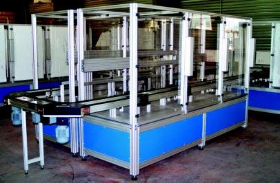
6 TLM 1000 Flexible and economical industrial system adapted to conveying workpiece carriers on assembly lines with automatic or manually operated work stations. 6
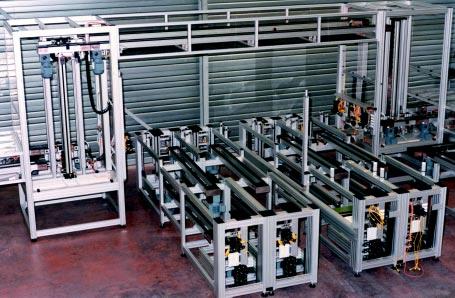
7 7
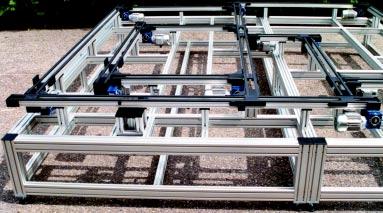

8 8


9 General principle Workpiece carriers are conveyed on two parallel belts which leave necessary room for stoppers, positioning units... Retractable pins, located under the workpiece carrier, allow : > guiding the workpiece carrier with four pins on straight sections, > guiding the workpiece carrier round bends with two pins (the other being retracted). The modular design of TLM 1000 and transfer system as well as the use of standard elements allow a great flexibility in the conception of assembly lines and reduce the time necessary for survey and implementation. Further extensions and modifications can be easily made. Existing line 9
10 Data TLM 1000 Workpiece carriers (mm) 100x x x x x x x x400 Load/workpiece carrier (dan) 2 10 Speed (m/mn) Length of conveying unit Mini Maxi Maxi accumulation load per motor (dan) V KW A Motor power 0,09 KW - 0,4 A 9 0,25 0,68 (380 V three-phases) 15 0,37 1,24 (different powers on request) 19 0,55 1,60 The maximum length of the conveying units are respectively : > 3160 mm for TLM 1000 > 6250 mm for For long spans, several elements can be joined end to end. For important accumulations, the length of the conveying units is adapted to the load. It is recommended to place sensors in order to control accumulation of the load. Pneumatic cylinders must be equipped with flow rate controllers. It is possible for long spans to be cut in order to facilitate the dismantling of the machines. 10
11 Sections TLM 1000 Width 100 Width 200 Width
 is used to fix the components and perform an accurate positioning of the workpiece carrier.")


12 Workpiece carriers Use : Workpiece carriers are used to support and position the components during the process. The upper plate (made of aluminium) is used to fix the components and perform an accurate positioning of the workpiece carrier. The PA base (which has a very low friction coefficient) is used to shelter the pins and to stop the workpiece carrier on the stopper. Steel bushes assure perfect accuracy and resistance against deterioration. Small metallic bars allow detection at stoppers and at positioning units. Workpiece carrier 100x150 Workpiece carrier 300x300 Unidirectional workpiece carriers : They are used in applications which don t require any swivelling. They allow operating with only one sensor in «stopper up mode». Multidirectional workpiece carriers : They can be used in case of swivelling of the workpiece carrier on the line, (90 and 180 for the square workpiece carriers, only 180 for the rectangular workpiece carriers). Details of workpiece carrier 90 kit : Necessary for a 90 swivelling of the workpiece carrier on the line. Including 2 bushes and 2 detection bars. 12
13 Workpiece carriers 1000TLM TLM 1000 Width 100 Working area : Plate Al Base, PA black 2 steel bushes 4 pins PA 4 springs 4 countersunk screws M4x10 2 detection bars 2 plugs Multidirectional workpiece carriers : Plate Al Base, PA black 4 steel bushes 4 pins PA 4 springs 4 countersunk screws M4x10 4 detection bars 4 plugs Weight : 100x100 : 0,41 kg 100x150 : 0,53 kg Maximum load : 2 dan Workpiece carrier 100x100 1 pce Multidirectional w. carrier 100x100 1 pce Workpiece carrier 100x150 1 pce
14 Workpiece carriers Unidirectional Width 200 Plate Al Base, PA black 2 steel bushes 4 pins PA 4 springs 3 countersunk screws M6x25 1 countersunk screw M6x16 2 detection bars 2 plugs Length Weight : 200x200 : 1,75 kg 200x250 : 2,20 kg 200x300 : 2,63 kg Maximum load : 10 dan Working area Workpiece carrier U 200x200 1 pce Workpiece carrier U 200x250 1 pce Workpiece carrier U 200x300 1 pce
15 Workpiece carriers Multidirectional Width 200 Plate Al Base, PA black 2 steel bushes 4 pins PA 4 springs 4 countersunk screws M6x25 2 detection bars 2 plugs Length Weight : 200x200 : 1,75 kg 200x250 : 2,20 kg 200x300 : 2,63 kg Maximum load : 10 dan Working area Option : 90 kit 2 detection bars 2 steel bushes 2 plugs Workpiece carrier M 200x200 1 pce Workpiece carrier M 200x250 1 pce Workpiece carrier M 200x300 1 pce kit 200x200 1 pce
16 Workpiece carriers Unidirectional Width Plate Al Base, PA black 2 steel bushes 4 pins PA 4 springs 9 countersunk screws M6x16 2 detection bars 2 plugs Width Length Weight : 300x300 : 3,10 kg 300x400 : 4,10 kg 400x400 : 5,40 kg Maximum load : 10 dan Working area Workpiece carrier U 300x300 1 pce Workpiece carrier U 300x400 1 pce Workpiece carrier U 400x400 1 pce
17 Workpiece carriers Multidirectional Width Plate Al Base, PA black 2 steel bushes 4 pins PA 4 springs 8 countersunk screws M6x16 2 detection bars 2 plugs Width Length Weight : 300x300 : 3,10 kg 300x400 : 4,10 kg 400x400 : 5,40 kg Maximum load : 10 dan Working area Option : 90 kit 2 detection bars 2 steel bushes 2 plugs Workpiece carrier M 300x300 1 pce Workpiece carrier M 300x400 1 pce Workpiece carrier M 400x400 1 pce kit 300 et pce


18 Conveying units Use Moving and accumulating workpiece carriers. The motor can be fitted either vertically or horizontally. According to the load, longer spans can be joined end to end by a straight joining. The cutting of the conveyors allow division of the length, making transport and installation of the lines easier. Conveying unit 100 They also allow to make important lengths for reduced loads. Spacers have to be fitted between the profiles every 1 m or 1,5 m to ensure a perfect parallelism of the profiles. Conveyor cut Straight joining Conveying unit
19 Conveying units TLM 1000 Width 100 Mini length : L = 500 mm Maxi length : L = mm For longer spans and according to the load, use several conveying units Spacer (1/m) Including : 1 idling unit 1 driving unit motor 380 V three-phases 0,09 KW Speed : 10, 15 or 20 m/mm (other speeds on request) Conveyor length : 2 profiles 40x20, al anodized 2 belt guides PA, black 2 welded belts width 12,5 mm thickness 1 mm, welded Maximum load /3 m : 50 dan Maximum accumulation load /3m : 25 dan Belt length in mm : L welded = [(L-160) x ] x 0,97 Weight : 8 kg +/m : 2,07 kg For L > 1 m : spacers ref , have to be fitted between the two profiles 5 40x20 (about 1 per metre). Weight : 0,042 kg Conveying unit pce Conveying lenght m A Spacer pce ( = speed of motor : ou 20 ex. : ) 19
20 Conveying units Width Minimum length : L = 500 mm Maximum length : L = mm For longer spans and according to the load, use several conveying units. Including : 1 idling unit 1 driving unit : Speed : 9, 15 or 19 m/mm (Other speeds on request) Motor : 230/400 V 3-phases 0,25 KW (9m/mn) 0,37 KW (15m/mn) 0,55 KW (19m/mn) Conveyor length : 2 profiles 80x40, Al anodized 2 belt guides PA, black 2 welded belts width 25 mm thickness 1,6 mm, welded Maximum load /6 m : 200 dan Maximum accumulation load /6 m : 100 dan Belt length in mm : L welded = [(L-100) x ] x 0,98 Weight 200 : 15,7 kg 300 : 18,5 kg 400 : 21,1 kg +/m : 6,7 kg 20 Spacer (1/1,5m) A = workpiece carrier width Antistatic option : To be ordered with the initial assembling: machining of the blocks 2 shouldered screws 2 steel rollers Conveyor unit pce Conveyor unit pce Conveyor unit pce Conveyor length m A Antistatic set 1 pce C ( = motor speed : 9-15 or 19 ex : )


21 Spacers Width Use If the length of the conveying unit is > 1,5 m spacers have to be fitted between the profiles 8 80x40. (1 spacer /1,5 m) Width 200 : Cast aluminium Width 300 et 400 : Profile 8 40x40 light 2 universal fastenings Spacer pce Spacer pce Spacer pce Straight joinings Width TLM Use Allow to join end to end two conveying units. Guide PA, black Joining set alu Weight 100 : 0,16 kg 200 : 0,18 kg Straight joining pce Straight joining pce

22 Height reductions Width Use For ergonomic manual stations (from a seated position). Enable reduction of the height of the conveyor in front of the worker. 2 spacers Including : - 2 spacers - 2 reducings PA - 1 profile 40x16-1 conduit profile 40x20 L maxi : 1500 mm L1 mini : 50 mm without cam without stopper 120 mm with cam Conveyor cuts Use Height reduction pce Height reduction pce Height reduction pce TLM 1000 They allow division of the conveyor lengths to make the transport and installation of the lines easier. They also enable the making of important lengths when the load is limited. TLM 1000 : length maximum 5 m 6 double universal fastenings 5 : length maximum 12 m 6 double universal fastenings 8 22 Lengths TLM m 5 m 7 m 8 m 9 m 10 m 11 m 12 m Loads maxi dan accumulation maxi dan Conveyor cut pce B Conveyor cut pce B


23 Cams Use Cams ED, EG, SD, SG Allow a perpendicular transfer of workpiece carriers from one conveying unit to the other. The workpiece carrier is guided by the two inside pins, the outside pins are retracted. They are also used for derivations. Cam EG 300 Short cams SD-EG SG-ED Double cams Short cams and double cams allow deviation of workpiece carriers from a main line to a parallel secondary line without additional motorization. Economical, compact and very easily managed, they are ideal to set up work stations in derivations. Do not accumulate the workpiece carriers in the cams. Cam EG 100 Short cams 200 Double cams
24 Cams ED, EG, SD, SG Width 100 TLM 1000 Complete set including : Guiding cam and pin retracting plates PA black Fastening parts Joining parts Different cams according to the dimensions of the workpiece carriers. If a selection is necessary (derivation or not) add the derivation set (p31). Lp=workpiece carrier length Cam ED Right inlet on main line. Cam SG Left oulet on main line. Do not accumulate the workpiece carriers in the cams. Lp=workpiece carrier length Cam EG Left inlet on main line. Cam SD Right outlet on main line. Weight ED - EG 100 : 0,36 kg SD - SG 100 : 0,32 Kg Cam ED set Cam EG set Cam SD set Cam SG set Cam ED set Cam EG set Cam SD set Cam SG set
25 Cams ED, EG, SD, SG Width Complete set including : Guiding cam and pin retracting plates PA black Fastening parts Joining parts Different cams according to the dimensions of the workpiece carriers. Lp=workpiece carrier length The cams 200 also allow the use of workpiece carriers 200x250 and 200x300. The cams 300 also allow the use of workpiece carriers 300x400. If a selection is necessary (derivation or not) add the derivation set (p32). Do not accumulate the workpiece carriers in the cams. Weight 200 : 0,91 kg 300 : 1,5 kg 400 : 1,9 kg Cam ED Right inlet on main line. Cam EG Left inlet on main line. Cam SG Left oulet on main line. Cam SD Right outlet on main line. Cam 300 and 400 Cam ED set Cam EG set Cam SD set Cam SG set Cam ED set Cam EG set Cam SD set Cam SG set Cam ED set Cam EG set Cam SD set Cam SG set
 add the derivation set (p.32).")
26 Short cams SD-EG, SG-ED Width 200 Complete set including : Cams and guides PA, black Fastening parts Screw and nut St PA M6 (1 set SD-EG + 1 set SG-ED are necessary to make a complete derivation) Minimum load on workpiece carrier : 2 dan They also allow the use of workpiece carriers 200x250 and 200x300. If a selection is necessary (derivation or not) add the derivation set (p.32). Do not accumulate the workpiece carriers in the cams. Weight : 2,2 kg Short cam 200 SD-EG 1 set Short cam 200 SG-ED 1 set
27 Short cams SD-EG, SG-ED Width Short cam 300 Complete set including : Cam and guides PA Fastening parts Screw and nut St PA M6 (1 set SD-EG + 1 set SG-ED are necessary to make a complete derivation) Minimum load on workpiece carrier : 2 dan The short cams 300 also allow the use of workpiece carriers 300x400. Short cam 400 If a selection is necessary (derivation or not) add the derivation kit (p.32). Do not accumulate the workpiece carriers in the cams. Weight 300 : 6,1 kg 400 : 13,2 kg Short cam 300 SD-EG 1 set Short cam 300 SG-ED 1 set Short cam 400 SD-EG 1 set Short cam 400 SG-ED 1 set
28 Double cams Width 200 Double cam 200 Complete set including : Cam, selectors, ramps and guides PA black 2 rotative cylinders, (M5) Fastening parts Screw and nut St PA M6 Minimum load on workpiece carrier : 2 dan They also allow the use of workpiece carriers 200x250 and 200x300. If a selection is necessary (derivation or not) add the derivation kit (p.32). Do not accumulate the workpiece carriers in the cams. Weight : 3,6 kg Double cam set
29 Double cams Width Double cam 300 Complete set including : Cam, selectors, ramps and guides PA black 2 rotative cylinders, (M5) Fastening parts Screw and nut St PA M6 Minimum load on workpiece carrier : 2 dan The double cams 300 also allow the use of workpiece carriers 300x400. Double cam 400 If a selection is necessary (derivation or not) add the derivation kit (p.32). Do not accumulate the workpiece carriers in the cams. Weight 300 : 5,4 kg 400 : 12,2 kg Double cam set Double cam set


30 Derivations Use Derivations have to be used with a cam. They allow divertion or not of the workpiece carrier by retraction of the pins on one side or the other of the conveyor. The two cylinders are controlled by only one solenoid valve. Derivation 200 Derivation
31 Derivations TLM 1000 Width 100 Set including : 2 plates Al 2 nuts 5 St M4 2 screws M4x10 Body, levers and guides PA 2 cylinders ø 16-5 (M5), detectable positions Cams are not included (must be ordered separately) Weight : 0,4 kg Derivation set
32 Derivations Width Set including : 2 plates Al 2 nuts St PA M6 2 screws M6x10 Body, levers, guides PA and screws and bolts 2 cylinders ø (G1/8), detectable positions 1protection Ac black Cams are not included (must be ordered separately) Weight 200 : 1,4 kg 300 : 1,5 kg 400 : 1,5 kg Derivation set Derivation set Derivation set

 Minimum load on the workpiece carrier : 0,3 dan Do not accumulate the workpiece carriers in the returns.")
33 Returns 180 Use 0 Allow the return of the workpiece carrier on a parallel conveyor with a reduced space between the two conveyors. The workpiece carrier is conveyed always keeping the same side towards the outside of the line. Width 100 TLM 1000 Housing aluminium 2 parallel belts driven by a bevel gear pair on a conveyor unit. (No additional motor) Minimum load on the workpiece carrier : 0,3 dan Do not accumulate the workpiece carriers in the returns. Weight : 8 kg Return pce
34 Returns 180 Width Motor plates alu black. 2 parallel belts driven by a gear motor. Plates and lateral guide supports PA, black. Screws and bolts. 300 Do not accumulate the workpiece carriers in the returns. Weight 200 : 16 kg 300 : 18,2 kg 300 Return pce Return pce
35 Returns 180 Width 400 Motor plates alu black. 2 parallel belts driven by a gear motor. Plates and lateral guide supports PA, black. Screws and bolts. Do not accumulate the workpiece carriers in the returns. Weight : 20 kg Return pce

 A stopper situated before the swivelling unit is generally necessary to avoid the arrival of another workpiece")
36 Swivellings Use 90 swivelling of workpiece carriers by blocking and retracting the pins. 180 swivelling of workpiece carriers by a linear rotating cylinder. Swivellings 90 TLM 1000 Width 100 Plates and guides PA, black 2 cylinders ø 16-5 (M5) 2 brackets for shielded mounting sensor M12x100 1 cylinder ø (M5) A stopper situated before the swivelling unit is generally necessary to avoid the arrival of another workpiece carrier during swivelling. Minimum load on workpiece carrier : 0,3 dan Weight : 1,8 kg Swivelling set
37 Swivellings 90 Width Swivelling x200 Plates and guides PA black 3 cylinders ø (M5) 1 stopper 2 brackets for shielded mounting sensor M12x100 Minimum load on workpiece carrier : 2 kg Swivelling x300 A stopper situated before the swivelling unit is generally necessary to avoid the arrival of another workpiece carrier during swivelling. Weight 200 : 3,8 kg 300 : 5,8 kg 400 : 6,9 kg Swivelling x400 Swivelling set Swivelling set Swivelling set Specify (R) for spring stopper ex. : (R) 37
38 Swivellings 180 Width Swivelling Stopper Linear rotating cylinder Sensor braket A stopper situated before the swivelling unit is generally necessary to avoid the arrival of another workpiece carrier during swivelling. Swivelling Flow rate controller should be adapted. Weight 200 : 5,6 kg 300 : 6,7 kg 400 : 7,6 kg Swivelling Swivelling set Swivelling set Swivelling set Specify (R) for spring stopper ex. : (R) 38


39 Lifts Use Allow the return of workpiece carriers above or below a line, or the transfert of workpiece carriers on several levels. Constructed from standard elements, each lift is adapted to the size of the workpiece carriers, the strokes and other line-specific parameters. Lift Only by consulting 39
40 Conveying unit stand Conveying unit stand Stand 100 Stand Use Support to fit conveying units on table or frame. 40x40 light 80x40 light 80x40 light Simple stand Use Support for one conveying unit. Built with profile 8 40 x 40, it is compatible with all item profiles and modular elements. 40x40 light light adjustable 80x40 light Double stand Simple stand Double stand Use To support two parallel conveying units. Built with profiles 8 80 x 40, it is compatible with all item profiles and modular elements. 40 Designation/Dimensions Order unit Référence Conveying unit stand set Conveying unit stand set Conveying unit stand set Conveying unit stand set Simple stand set Simple stand set Simple stand set Double stand set Double stand set Double stand set (Specify H and F in mm)


41 Stoppers Use Stopping workpiece carriers during processing requiring no accuracy. Stopping the workpiece carriers in order to respect conveying priorities at the end of the derivation. Stoppers 100 Stopper with simple or double effect, supplied with lateral guides and sensor bracket for detection of workpiece carriers. Stoppers Can be supplied with a spring to make the stopper rod pop out in case of an emergency stop. Supplied with sensor bracket for detection of workpiece carriers. Stopper 200 Short stoppers Thanks to the combination of small size and reduced height, the short stopper allows construction of ergonomic work stations along the line. Reduced accumulated load. Stopper
42 Stoppers Simple effect - Double effect Width 100 TLM 1000 Plate Al, black Body and stopper PA Nuts 5 St M5 + screws Holes for shielded mounting sensor M12x100 Detection range : 4 mm Maximum load : 10 dan (in accumulation) Flow rate controller M5 should be adapted Weight : 0,14 kg Stopper 100 simple effect 1 pce Stopper 100 double effect 1 pce
43 Stoppers Width stroke 10 Stopper rod (polyurethane coated) Complete set with double effect cylinder ø 32 mm, detectable positions Bracket for shielded mounting sensor M12x100 Detection range : 4 mm Maximum load : 50 dan (in accumulation) Flow rate controller G 1/8 should be adapted Weight 200 : 1,3 kg 300 : 1,7 kg 400 : 2 kg Stopper pce Stopper pce Stopper pce Specify (R) for stopper with spring ex. : (R) 43
44 Short stoppers Width Stopper rod (polyurethane coated). Complete set with double effect cylinder ø 20 mm, detectable positions. Bracket for shielded mounting sensor M12x100. Detection range : 4 mm. Stoppers : 1 profile 8 40 x 40 light 2 universal fastening set 8 Maximum load : 50 dan (in accumulation). Flow rate controller G 1/8 should be adapted. Weight 200 : 0,9 kg 300 : 1,4 kg 400 : 1,8 kg Short stopper pce Short stopper pce Short stopper pce Specify (R) for spring stopper ex. : (R) 44

 at the center of the workpiece carrier.")

45 Positioning units Use Stopping and positioning workpiece carriers for operations requiring accuracy. The workpiece carrier is stopped, then lifted off the belts and positioned by two centering pieces. Positioning units : The positioning unit is directly fitted on the conveying units. Positioning units for station: They are fixed to a table or a frame in order to assure accuracy with the other surrounding elements. Positioning unit 100 Heavy positioning units : For operations requiring accuracy, and involving important strain (up to 1500 dan) at the center of the workpiece carrier. The positioning unit must be fixed on a frame capable of supporting the strain applied. Lift positioning units : Stop and positioning of workpiece carriers at an important height above the conveyor. The workpiece carrier is stopped, then elevated to a specific height, while being held by two centering pieces. Positioning unit 200 Press positioning units : Support important strain (5000 dan) on the surface between the 2 belts. The positioning unit must be fixed on a frame capable of supporting the strain applied. Multi-positioning units : Allow two accurate positionings of the workpiece carrier at the same station. Positioning unit
46 Positioning units TLM 1000 Width ,5 positioned Complete set including : Stopper Positioning unit Anti bouncing back device 1 double effect cylinder ø 32, detectable positions Holes for shielded mounting sensor M12x100 Detection range : 4 mm Positioning unit 100 Flow rate controller G 1/8 should be adapted Maximum vertical strain : 40 dan for a pressure of 6 bars Repeatability : +/- 0,03 mm Weight : 2 kg Positioning unit 100 with simple effect or double effect stopper Positioning unit pce Simple effect 1 pce Double effet 1 pce
47 Positioning units TLM Width Positioning unit 200x200 to 200x300 Complete set including : Stopper Positioning unit 1 double effect cylinder ø 32 (stopper) 1 double effect cylinder ø 50 (positioning unit) detectable positions Holes for shielding mounting sensor M12x 100 Detection range : 4 mm 120,5 positioned Positioning unit 300x300 to 400x400 Flow rate controller G 1/8 should be adapted 110,5 positioned Maximum vertical strain : 100 dan for a pressure of 6 bars Repeatability : +/- 0,03 mm A = width of workpiece carrier B = length of workpiece carrier Weight 200 : 8,7 kg 300 : 10,5 kg 400 : 12,2 kg Positioning unit pce Positioning unit pce Positioning unit 300x400 1 pce Positioning unit pce Specify (R) for spring stopper ex. : (R) 47
48 Positioning units Positioning units for station TLM 1000 Width positioned Complete set including : Stopper and positioning unit 1 double effect cylinder ø 32, detectable positions Holes for shielded mounting sensor M12x100 Detection range : 4 mm 4 supports in profile 8 40x40 Fastening parts Flow rate controller G 1/8 should be adapted Maximum vertical strain : 40 dan for a pressure of 6 bars Repeatability : +/- 0,03 mm Weight : 3,4 kg Positioning unit for station pce Pos. unit for station 100 simple effect 1 pce Pos. unit for station 100 double effect 1 pce
49 Positioning units Positioning units for station Width Complete set including : Stopper 1 double effect cylinder ø 32 (stopper) 1 double effect cylinder ø 50 (positioning unit) detectable positions Holes for 2 inductive sensors M12x100 Detection range : 4 mm 4 supports in profile 8 40x40 Fastening parts Positioning unit 200x200 to 200x ,5 positioned Positioning unit 300x300 to 400x ,5 positioned Flow rate controller G 1/8 should be adapted Maximum vertical strain : 100 dan for a pressure of 6 bars Repeatability : +/- 0,03 mm A = width of workpiece carrier B = length of workpiece carrier Weight 200 : 10,2 kg 300 : 11,2 kg 400 : 13 kg Positioning unit for station pce Positioning unit for station pce Positioning unit for station 300x400 1 pce Positioning unit for station pce Specify (R) for spring stopper ex. : (R) 49
50 Positioning units Heavy positioning units Width 100 TLM 1000 Complete set including : Stopper Positioning unit 1 double effect cylinder ø 25, detectable positions Holes for shielded mounting sensor M12x100 Detection range : 4 mm regulating wedge 160 positioned Flow rate controllers G 1/8 should be adapted Maximum vertical strain : 500 dan at the center of the workpiece carrier Repeatability : +/- 0,03 mm Weight : 8,7 kg Heavy positioning unit pce Heavy pos. unit 100 simple effect 1 pce Heavy pos. unit 100 double effect 1 pce
51 Positioning units Heavy positioning units Width Positioning unit 200x200 to 200x300 Complete set including : Stopper Positioning unit 2 pneumatic cylinders, detectable positions Profile stands 8 40x40 Fastening parts Holes for shielded mounting sensors M12x100. Detection range : 4 mm 120,5 positioned Positioning unit 300x300 to 400x400 Flow rate controllers G 1/8 should be adapted 110,5 positioned Maximum vertical strain : 1500 dan at the center of the workpiece carrier (60x60 mm) Repeatability : +/- 0,03 mm A = width of workpiece carrier B = length of workpiece carrier Weight 200 : 18,3 kg 300 : 19,6 kg 400 : 21,8 kg Heavy positioning unit pce Heavy positioning unit pce Heavy positioning unit 300x400 1 pce Heavy positioning unit pce Specify (R) for spring stopper ex. : (R) 51
52 Positioning units Lift positioning units Width 100 stroke-e TLM 1000 Complete set including : Impulse controlled stopper and anti bouncing back devices 1 double effect cylinder ø 32 Ball bearing guide bush ø 14 1 bracket for shielded mounting sensor M12x100. Detection range : 4 mm stroke +83 Cylinder strokes available : mm Flow rate controller M5 and G 1/8 should be adapted Maximum vertical strain : 40 dan for a pressure of 6 bars Repeatability : +/- 0,06 mm Weight : 3,4 kg Lift positioning unit 100 simple effect 1 pce Lift positioning unit 100 double effect 1 pce
 1 cylinder ø 50 (positioning unit), detectable positions Spacers Fastening parts 2")
53 Positioning units Lift positioning units Width stroke-10 fastening set Complete set including : Stopper Positioning unit Ball bearing guide bush ø 25 1 cylinder ø 32 (stopper) 1 cylinder ø 50 (positioning unit), detectable positions Spacers Fastening parts 2 brackets for shielded mounting sensor M12x100. Detection range : 4 mm Cylinder strokes available : mm stroke 17,5+stroke Example of regulating wedge for mounting on table A = width of workpiece carrier Flow rate controller G 1/8 should be adapted A stopper situated before the lift unit is generally necessary to avoid the arrival of another workpiece carrier during lifting. Maximum vertical strain : 100 dan for a pressure of 6 bars Repeatability : +/- 0,06 mm Weight 200 : 10,6 kg 300 : 19,6 kg 400 : 22,5 kg Fastening set under the conveyor fastening set Lift positioning unit pce Lift positioning unit pce Lift positioning unit 300x400 1 pce Lift positioning unit pce Fastening set 1 pce Specify (R) for spring stopper ex. : (R) 53

54 Positioning units Press-positioning units Width 200 Positioning unit 200x200 to 200x ,5 positioned Complete set including : Stopper Lifting cylinder 2 locking cylinders Fastening parts Holes for shielded mounting sensor M12x100. Detection range : 4 mm Positioning unit 300x300 to 400x400 Flow rate controller G 1/8 should be adapted The press-positioning unit must be fixed on a frame capable of supporting the strain applied. Maximum vertical strain : 200x200 : dan 300x300 : dan 400x400 : dan 110,5 positioned A = width of workpiece carrier B = length of workpiece carrier Repeatability : +/- 0,03 mm Press-positioning unit 200x200 1 pce Press-positioning unit 300x300 1 pce Press-positioning unit 300x400 1 pce Press-positioning unit 400x400 1 pce Specify (R) for spring stopper ex. : (R) 54
55 Positioning units Multi-positioning units Width 100 Complete set including : Stopper Positioning unit 100 Slide PS 20 Strokes : ou 200 The slide is fitted with shock absorbers and stop screws with integrated sensors. 200 positioned Maximum vertical strain : Strokes 50 ou 100 : 40 dan Stroke 200 : 20 dan 142+stroke 187+(2 x stroke) Repeatability : +/- 0,04 mm A stopper situated before the lift unit is generally necessary to avoid the arrival of another workpiece carrier during the slide moving stroke Weight : 7,4 kg Multi-positioning unit pce ( = strokes ex. stroke 50 : ) 55

56 Positioning units Multi-positioning units Width 200 Complete set with : Stopper Positioning unit 200 Slide PS 20 Strokes : ou 200 The slide is fitted with shock absorbers and stop screws with integrated sensors. 284 positioned Maximum vertical strain : Strokes 50 ou 100 : 40 dan Stroke 200 : 20 dan 142+stroke 187+(2 x stroke) Repeatability : +/- 0,04 mm A stopper situated before the lift unit is generally necessary to avoid the arrival of another workpiece carrier during the slide moving stroke Weight : 14,5 kg Multi-positioning unit pce ( = strokes ex. stroke 50 : ) 56
57 Sensor bracket M12x100 TLM 1000 Use Bracket for workpiece carrier M12x100 sensor. : Stainless steel 2 mm Nut 5 St M4 + screws Cast aluminium Nut 8 St M6 + screw Weight 100 : 0,035 kg 200 : 0,1 kg 300 : 0,1 kg 400 : 0,1 kg Sensor bracket pce Sensor bracket pce Sensor bracket pce Anti bouncing back TLM 1000 Use Avoids workpiece carrier buncing back on stoppers or positioning units in case of high speed. Allows to reduce the changing time of workpiece carriers in the positioning unit. Parts, PA black Fastening parts Weight : 0,1 kg Anti bouncing back set Anti bouncing back set

58 Logic block TLM 1000 reading or printing Use Allows simple identification of workpiece carriers and memorising information at different stages of the line. The coder consists in a plastic body in which steel ball can only have two stable positions. Coding is done by changing the position of the ball with a micro cylinder. Reading is done by magnetic detection. Resetting can be done simply by running the coder under a fixed cam. One coder is equivalent to 1 byte of memory. Several coders can be placed side by side on the same workpiece carrier. RAZ per cam (M3x30) Body, PA black Steel ball ø 10 R.A.Z Weight : Logic block : 0,018 kg RAZ : 0,19 kg Logic block 1 pce R.A.Z pce R.A.Z pce
59 Inductive sensor M12x100 Use Detection for the workpiece carrier Shielded mounting sensor M12x100 detection range : 4 mm LED control display PNP VDC Screwed connection, cable 5 m Sensor M12x100 1 set Cylinder sensor Use Detecting the position of cylinders, stoppers or positioning units V LED control display Cable 5 m Sensor for cylinder, Stopper, Positioning unit 1 set Sensor for cylinder, Lift Positioning unit 1 set Positioning kit Use Allows accurate positioning unit on station. Positioning unit 2 axis screws M8 2 hexagon socket head cap screws M8 Weight : 0,08 kg Machining for positioning kit Positioning kit 1 set
60 Belt welding kit Use Welding bevelled conveyor belts. Each kit includes : - 1 belt tension system - 1 thermic press - 1 jar of glue Belt welding kit 1 set Bevelling device Use Bevelling belts before welding. Bevelling device 1 set Belt Use Belt for the moving of pallets on conveying units Antistatic. TLM 1000 : 12,5 x 1 mm : 25 x 1,6 mm Belt 12,5 x 1 mm m Belt 25 x 1,6 mm m Glue (40 g) 1 jar
61 CAD files Use CAD-data as.dwg and.dxf files..dwg files on request.dxf files on request 61
62 Layout example Stopper Positioning unit 62
63 Elcomodularity According to the requirements of the manufacturing process, different kinds of modular designs are possible. The design of the line can evolve in several stages. 1. Interchangeability of a module - 4 fixing screws only - No machining - No adjusting 2. Adding a derivation - 6 fixing screws - No machining - No adjusting 63
LA LIBERTÉ DE CONCEVOIR. Modular transfer systems
 Modular transfer systems FRENCH INDUSTRIAL LEADER has brought innovating solutions to the industry. Our approach offers a complete freedom of design thanks to a unique range of flat belt conveyor and modular
MODULAR TRANSFER SYSTEM
 MODULAR TRANSFER SYSTEM & conveyors new PRODUCTS 2014 LA LIBERTÉ DE CONCEVOIR FRENCH INDUSTRIAL LEADER has brought innovating solutions to the industry. Our approach offers a complete freedom of design
NEWS Part. N /0 MINITEC NEWS
 NEWS 2009 Part. N 95.0423/0 MINITEC NEWS 2009 1 TABLE OF CONTENT INTRODUCTION CONTENTS 3 END CAP Z WITH HAMMER TAPS 3 END CAP 45X45 VA 4 ANGLE 25 GD-Z 4 ANGLE 45X90 GD-Z 5 ANGLE 90 GD-Z 5 HINGE 19 S 6
 488 PARTS LIST 1 3 SCREWS FOR NO. 2 2 FLYWHEEL CAP 3 FLYWHEEL 4 END NUT FOR NO. 10 5 BALL BEARING FOR NO. 3 (1 st ) 6 BALLBEARING FOR NO. 3 (2nd) 7A CLUTCH RACE KEY 7B CLUTCH RACE 7C CLUTCH SPRING 7D 7
Adjustable Feet Castors Accessories for Floor Elements
 Adjustable Feet Castors Accessories for Floor Elements Products in this section Levelling Knuckle Feet Threaded spindles for infinite height adjustment Metal or plastic foot plate Knuckle Feet X Compatible
SUMMARY. V-Lock SYSTEM BASIC ELEMENTS ACTUATORS. P V-Lock GENERAL INTRODUCTION 2. P V-Lock FIXING ELEMENTS 10 SUMMARY. P V-Lock ADAPTORS 17
 SUMMARY A3 V-Lock SYSTEM P V-Lock GENERAL INTRODUCTION 2 BASIC ELEMENTS P V-Lock FIXING ELEMENTS 10 P V-Lock ADAPTORS 17 SUMMARY P PROFILES 28 P V-Lock ACCESSORIES AND SPARE PARTS 32 1 A3 GENERAL INTRODUCTION
L40. Pneumatic linear slide L40
 L40 Pneumatic linear slide High stiffness and deflection resistance. Up to 30kg on the carrier. Guidance with recirculating ball-bearings. Exclusive belt drive system. Hydraulic shock-absorbers on the
Clamping devices 521
 Clamping devices 521 522 Product overview Clamping devices Adjustable straps K0001 Hook clamps K0012 Goose-neck straps with long slot K0002 Page 526 Hook Clamps with collar K0013 Page 535 Equipped clamps
ALFRA PRESS. Made in Germany by ALFRA
 52 ALFRA PRESS Made in Germany by ALFRA 53 ALFRA PRESS Overview ALFRA PRESS AP 250 ALFRA PRESS AP 400 Page 56 Page 58 Control cabinet housing, control cabinet doors, mounting plates Control cabinet housing,
Hours / 100 Marks Seat No.
 17610 15116 4 Hours / 100 Seat No. Instructions (1) All Questions are Compulsory. (2) Answer each next main Question on a new page. (3) Illustrate your answers with neat sketches wherever necessary. (4)
Model No: TC10. Parts Information: Tyre Changer - Automatic
 Page 1 of 11 1 TC10.01 BODY 2 TC10.02 COLUMN 3 TC10.03 HORIZONTAL ARM ASS'Y 4 TC10.04 WASHER 5 TC10.05 RUBBER FOOT 6 TC10.06 COVER 7 TC10.07 SCREW M14x42 8 TC10.08 PRESS COVER 9 TC10.09 STOP-UP 10 TC10.10
Roller Guides C-Rail Systems Linear Guide Systems Ball-Bearing Guide Bushes Ball-bush block guides Shafts Accessories for Linear Slides
 Roller Guides C-Rail Systems Linear Guide Systems Ball-Bearing Guide Bushes Ball-bush block guides Shafts Accessories for Linear Slides Application example linear systems, drives and accessories 1 2 3
HYDRAULIC CONTROL DETAILS PARTS LIST
 Always give model number, serial number and part number when ordering repair parts. HYDRAULIC CONTROL DETAILS PARTS LIST REF NO. PART NUMBER DESCRIPTION 1 101939 Hydraulic Tank 2 101940 Hydraulic Tank
Zero Point Clamping System. ZERO lock BALL lock
 Zero Point Clamping System ZERO lock BALL lock kap3 kap 263 Technical information regarding ZERO lock Zero Point Clamping System Application The modularly designed, flexible ZERO lock Zero-Point Clamping
aluminium profile system
 aluminium profile system 63 AME System aluminium profiles overview series profiles introduction 80x80 x80 x80/180 x Aluminium profiles are provided with longitudinal grooves which can be used in conjunction
Signature. Date. Surname. 30 max.
 ITEM QTY PART NUMBER DRG - DRG - DRG - DRG 9- TCR DESCRIPTION Trolley Low Headroom Frame TCR / TCR Link Plate Spacer Air Hoist Title of project Date Material Weight Designed by Approved by Surname Date
n Measurable displacements between n Linearity: max. ± 0.05 % n Housing diameter 12.9 mm n Service life: 10 8 movements
 Potentiometric Displacement Sensor Miniature design Model 8709 Code: Delivery: Warranty: 8709 EN ex stock 24 months Application Potentiometric displacement sensors are used for direct, precise measurement
FEET, WHEELS, FLOOR FASTENINGS, SUPPORTS
 SYSTEM COMPONENTS FEET, WHEELS, FLOOR FASTENINGS, SUPPORTS s t r oppu S, s gn i n e t s af r oo l F, s l eehw, t e ef FEET, WHEELS, FLOOR FASTENINGS, SUPPORTS 136 MINITEC PROFILE SYSTEM BASE AND TRANSPORT
8 x 5 PLANER THICKNESSER OPERATING INSTRUCTIONS MODEL: W588
 8 x 5 PLANER THICKNESSER OPERATING INSTRUCTIONS MODEL: W588 Charnwood, Cedar Court, Walker Road, Bardon, Leicestershire, LE67 1TU Tel. 01530 516 926 Fax. 01530 516 929 Email; sales@charnwood.net website;
Line XMS the integrated machine concept
 Line XMS the integrated machine concept New Products 2012/ II XMS the innovative item concept for integrated machine constructions. 6 Profiles XMS A stable frame for modular machines. Cutting-edge design
Clamping bolts Eccentrical cams clamping units
 2.3 Shaft Clamping bolts Eccentrical cams clamping units 2.9 2.8 2.7 2.6 2.5 2.4 2.3 2.2 2.1 2.3 Clamping bolts, Eccentrical cams, Shaft clamping units Page 641 2.3 Clamping bolts, Eccentrical cams, Shaft
PREASSEMBLED ELEMENTS FOR LIFTING AND SLIDING DOORS
 PROFILE SYSTEM PRE-ASSEMBLED ELEMENTS FOR LIFTING AND SLIDING DOORS s r ood gni d i l s dna gni t f i l r o f s t neme l e de l bme s s a - er P PREASSEMBLED ELEMENTS FOR LIFTING AND SLIDING DOORS MINITEC
red rooster REV. TCR500 / TCR 1000 Link Plate 2TE Air Trolley (2TE/AT/4) DESCRIPTION Air Hoist PART NUMBER DRG TCR 1000 DRG
 DESCRIPTION Air Hoist PART NUMBER DRG TCR 1000 DRG") ITEM QTY PART NUMBER DRG 5- TCR DRG 5- DESCRIPTION TE Air Trolley (TE/AT/) Air TCR5 / TCR Link Plate TE and Trolley 6/6/ - 6kg Title of project Material Weight REV. Designed by Checked by Approved by B.
ITEM QTY PART NUMBER DRG 5- TCR DRG 5- DESCRIPTION TE Air Trolley (TE/AT/) Air TCR5 / TCR Link Plate TE and Trolley 6/6/ - 6kg Title of project Material Weight REV. Designed by Checked by Approved by B.
PRESENTATION. All machining Repetitive machining. The choice of a wide range of varied clamps that correspond to the individual s needs
 KOPAL PRESENTATION Vertical pressure clamping System KOPAL With neither riser block nor adjusting required, the system allows a continuous adaptation of the clamping height whilst retaining the clamping
Especially suitable for work in restricted working spaces.
 Innovative ratchet pipe cutter with a worldwide patent and ratchet mechanism allows you to cut a pipe without having o completely rotate the tool. Especially suitable for work in restricted working spaces.
25-200H. 12 Planer / Jointer. with Helical Cutterhead. Parts List.
 25-200H 12 Planer / Jointer with Helical Cutterhead 4001824 Parts List www.rikontools.com CABINET ASSEMBLY PARTS EXPLOSION & PARTS LIST KEY NO. DESCRIPTION KEY NO. DESCRIPTION 1 Pan Head Screw M6x12 P25-200H-1
Click Here to Go Back
 Click Here to Go Back Fig. -94 Fig. -97 CC42D 10. Remove the cap screw securing the gear shift stopper plate pin retainer; then remove the retainer. Fig. -95 CC45D 12. Remove the link arm and account for
Brake Gears Suspension Body - TCS
 Brake Gears Suspension Body - TCS-980 Brake Gears Suspension Body - TCS-980 100 426230A00 CENTRE HOUSING 1 101 426230A50 LOAD SHEAVE 1 102 426230200 COUPLING 1 103 426230350 CHAIN GUIDE 1 104 426230360
Parts Catalog. S-Series Slicer Smart Manual SG13. Model:
 , 07 99507 ECN 065 Parts Catalog S-Series Slicer Smart Manual Model: SG SG 0/0/07 Rev. G IMPORTANT! TO EXPEDITE SHIPMENT OF PARTS, ALWAYS SPECIFY MODEL, REV, PART NUMBER, AND SERIAL NUMBER OF UNIT. GLOBE
PANIC BARS Marking IN ACCORDANCE WITH 1125:1997/A1:2001
 PANIC BARS Marking IN ACCORDANCE WITH 25:997/A:200 Exclusive PININFARINA design Full adaptability in application Quick and easy installation Reliable and safe performance Tested up to 2.000.000 cycles
Enclosures, guards and partitions 6. Clamp Profiles Hangers Dual-Rod Mesh Hanger Lifting-Door System Door Security
 Clamp Profiles Hangers Dual-Rod Mesh Hanger Lifting-Door System Door Security Application example system solutions for enclosures and guards Components for building enclosures and guards 1 2 3 4 5 7 194
BASIC MACHINE with X pressure bar units L 3000 with 10 t pressure force each with jig arm (C-Frame) consoles positioned on the outside of the
 consoles positioned on the outside of the") BASIC MACHINE with a torsion free machine bed which is equipped with banjo bolts to fix the machine on the ground with a linear guiding and a toothed belt driving unit for the grinding unit drive of the
BASIC MACHINE with a torsion free machine bed which is equipped with banjo bolts to fix the machine on the ground with a linear guiding and a toothed belt driving unit for the grinding unit drive of the
Exploded View Saw Base - Model 7060 Semi-Automatic Cut-Off Band Saw
 Exploded View Saw Base - Model 7060 Semi-Automatic Cut-Off Band Saw 136 137 135 134 132 131 133 113 114 115 117 116 118 119 120 121 79 78 77 107 108 65 76 110 109 66 10 9 6 11 5 4 8 7 75 74 73 72 111 112
Pull-down clamps. No Low height clamping jaws, model Bulle
 Pull-down clamps The wedge action of clamping jaws is the characteristic feature of these pull down clamps. It causes the pull down effect, which presses the workpiece against both, stop and machine table.
Model W1739 Variable Speed Planer Moulder Manual Insert
 Model W1739 Variable Speed Planer Moulder Manual Insert READ and understand this W1739 manual insert and the W1693 instruction manual before using this machine. Ignoring this warning may lead to serious
ASSEMBLY MANUAL POLAR GRIPPERS
 ASSEMBLY MANUAL POLAR GRIPPERS 2012 TABLE OF CONTENTS TABLE OF CONTENTS... 2 PRESENTATION... 3 AMG GRIPPERS FOR ROBOTS... 4 PREPARATION OF THE PARTS... 5 PREPARING A MAIN BOOM... 6 PREPARING A SECONDARY
Parts Catalog Admiral 28 Cylindrical Scrubber
 Parts Catalog Table of Contents Front bounce protection (97116834)... 4 Wheel suspension (97103725)... 6 Chassis (97115422)... 8 (97114763)... 10 Steering (97073738)... 12 Seat bracket (97118616)... 14
OPERATING INSTRUCTIONS
 GB OPERATING INSTRUCTIONS Automatic Wedge Welding Machine Please read operating instructions carefully before use and keep for further reference. APPLICATION The is an automatic wedge welding machine for
BETEX MECHANICAL PULLERS. BETEX MSP 2/3-arm pullers, self-centering. Safe and easy dismounting of bearings, couplings, rings etc.
 BETEX MSP 2/3-arm pullers, self-centering Safe and easy dismounting of bearings, couplings, rings etc. Ergonomic design, easily operated by one person! Practical! Self centering 2 or 3-arm puller with
2014 / Universal 5 Axis Vise Positive high strength clamping close to the work-piece Obstruction free 5-axis machining
 21 / 215 Vischer & Bolli Machining and workholding Universal 5 Axis Vise Positive high strength clamping close to the work-piece Obstruction free 5-axis machining Obstruction free 5-side machining More
Catalog of CLA force and torque sensors
 Catalog of CLA force and torque sensors SC-002 LC-01 LC-10 TSF-000 TSF-05 TSF-1 TSF-100 Micro-force sensor Force sensor Micro-torque sensor Torque sensor Phone +41 32 421 44 90, Fax +41 32 421 44 91, ventes@cla.ch,
Leveling Feet, Base Plates and Casters
 Leveling Feet, Base Plates and Casters 77 Leveling Foot 1 1 Fastening to profile end Fastening in T-slot of profile For leveling tables and light equipment. Ratchet-type height adjustment requires no tools.
Components made of special materials. Floor Elements for Profile St Profile KH. Fastening Elements for Profile KH
 Profile Fastening Elements for Profile Floor Elements for Profile Profile KH Fastening Elements for Profile KH Components made of special materials Products in this section Profile 8 x eel profile that
RYOBI 10 IN (254 MM) TABLE SAW MODEL NO. BT REPAIR SHEET
 TABLE SAW MODEL NO. BT REPAIR SHEET") RYOBI 0 IN (2 MM) TABLE SAW MODEL NO. BT00- REPAIR SHEET 2 RYOBI 0 in. (2 mm) TABLE SAW - MODEL NO. BT00- FOR MITER TABLE ASSEMBLY, REFER TO FIGURE B FOR BLADE GUARD ASSEMBLY, REFER TO FIGURE E FOR RIP
RYOBI 0 IN (2 MM) TABLE SAW MODEL NO. BT00- REPAIR SHEET 2 RYOBI 0 in. (2 mm) TABLE SAW - MODEL NO. BT00- FOR MITER TABLE ASSEMBLY, REFER TO FIGURE B FOR BLADE GUARD ASSEMBLY, REFER TO FIGURE E FOR RIP
FD 125 Large-Format Card Cutter
 FD 125 Large-Format Card Cutter 3/201 OPERATOR MANUAL Page 2 Table of Contents SAFETY PRECAUTIONS... 4 Introduction... 5 Specifications... 5 Accessories... 5 Major Components and Assemblies... 6 Control
Alufix Basic Sets offer a variety of application possibilities based on the quantity of components (from 19 to over 440) and their composition
 and their composition") ALUFIX BASIC SETS 2 ALUFIX BASIC-SETS Alufix Basic Sets offer a variety of application possibilities based on the quantity of components (from 19 to over 440) and their composition ALUFIX BASIC-SETS Note:
ALUFIX BASIC SETS 2 ALUFIX BASIC-SETS Alufix Basic Sets offer a variety of application possibilities based on the quantity of components (from 19 to over 440) and their composition ALUFIX BASIC-SETS Note:
K15.12 ROLLENBAND K15 DOORS
 K15 DOORS 01.04.2015 Waregemstraat 5-9870 Zulte - Belgium - T. +32 9 388 88 81 - F. +32 9 388 88 21 - commercial@sobinco.com - www.sobinco.com CONTENTS 1. General characteristics....03 2. Application range....03
1. Enumerate the most commonly used engineering materials and state some important properties and their engineering applications.
 Code No: R05310305 Set No. 1 III B.Tech I Semester Regular Examinations, November 2008 DESIGN OF MACHINE MEMBERS-I ( Common to Mechanical Engineering and Production Engineering) Time: 3 hours Max Marks:
Precision made in Germany. As per DIN The heart of a system, versatile and expandable.
 1 Precision made in Germany. As per DIN 8606. The heart of a system, versatile and expandable. Main switch with auto-start protection and emergency off. Precision lathe chuck as per DIN 6386 (Ø 100mm).
3. Barrier elements. Barrier posts. Stainles steel
 3. Urban Equipment Building Equipment Stainles steel e 3.1 Tubular hoops 216-223 3.2 Access barriers 224-227 3.3 Height restriction barriers 228-231 3.4 Protective railing 232-237 3.5 City fence 238-240
CATALOG OF REPLACEMENT PARTS
 The Choice of Experience CATALOG OF REPLACEMENT PARTS MODELS 909A 919A 909E 919E 909M 919M SLICERS EFFECTIVE MARCH 2009 - 2 - Table of Contents 5 ELECTRICAL COMPONENTS (909A & 919A) 7 ELECTRICAL COMPONENTS
For Euro grooves and NC International profiles
 RIBANTA For Euro grooves and NC International profiles - All accessories are frontally applied - Connection rods are modular and provided already pre-cut to standard sizes - All parts are pre-assembled
Repair Manual MWS45A-MWS50A-MWS55A MW32A-MWS36A-MWS40A. Ref Rev.D General Pump is a member of the Interpump Group
 MW/S 8 Repair Manual MWS45A-MWS50A-MWS55A MW32A-MWS36A-MWS40A General Pump is a member of the Interpump Group INDEX 1. INTRODUCTION..................................................Page 3 2. REPAIR INSTRUCTIONS...........................................Page
SPARE PARTS LIST MODEL NO PAGE 1 ITEM PART NO. DESCRIPTION QTY NOTE
 PAGE 1 001 342186-7 SWITCH PROTECTOR 1 002 911118-1 PAN HEAD SCREW M4X12 6 003 155512-9 SWITCH PLATE 1 004 651757-2 SWITCH ABK266 1 006 685712-2 SPONGE SHEET 60X60 1 007 911118-1 PAN HEAD SCREW M4X12 1
CONDITIONS OF SALE AND WARRANTY
 CONDITIONS OF SALE AND WARRANTY 1. Read carefully this operator's handbook before operating our P35 corking machine. 2. F.lli Marchisio & C.Spa guarantees his P35 corking machine in case of breakages caused
Parts Catalog. S-Series Slicer Manual Frozen Option S13. Model:
 , 07 995 ECN 08 Parts Catalog S S-Series Slicer Manual Frozen Option Model: S 05/0/07 Rev. G IMPORTANT! TO EXPEDITE SHIPMENT OF PARTS, ALWAYS SPECIFY MODEL, REV, PART NUMBER, AND SERIAL NUMBER OF UNIT.
Electrical height adjustment. ... easy & reliable. Multilift II telescope Multilift II. Synchron
 Electrical height adjustment... easy & reliable 07/2017 Multilift II telescope Multilift II Synchron Preface The Multilift lifting column has been tried-and-tested over many years in many customer applications.
RYOBI 10 in. (254 mm) TABLE SAW MODEL NO. BT3100 REPAIR SHEET
 TABLE SAW MODEL NO. BT3100 REPAIR SHEET") RYOBI 0 in. (4 mm) TABLE SAW MODEL NO. BT00 REPAIR SHEET FOR MITER TABLE ASSEMBLY, REFER TO FIGURE B FOR BLADE GUARD ASSEMBLY, REFER TO FIGURE E FOR RIP FENCE ASSEMBLY, REFER TO FIGURE C FOR MOTOR ASSEMBLY,
RYOBI 0 in. (4 mm) TABLE SAW MODEL NO. BT00 REPAIR SHEET FOR MITER TABLE ASSEMBLY, REFER TO FIGURE B FOR BLADE GUARD ASSEMBLY, REFER TO FIGURE E FOR RIP FENCE ASSEMBLY, REFER TO FIGURE C FOR MOTOR ASSEMBLY,
M4 Hex Nut [ ] M4 T-Nut 20 [20-044] Appx. 1. 3mm. 20 Series profiles (1 per hole) (1 per hole) Ordering Information
![M4 Hex Nut [ ] M4 T-Nut 20 [20-044] Appx. 1. 3mm. 20 Series profiles (1 per hole) (1 per hole) Ordering Information](/thumbs/77/74547895.jpg "M4 Hex Nut [ ] M4 T-Nut 20 [20-044] Appx. 1. 3mm. 20 Series profiles (1 per hole) (1 per hole) Ordering Information") Handles & Light Duty PA 20 1 Assembly of Hinge M4x8 FHCS [24-208-4] M4 T-Nut 20 [20-044] M4 Hex Nut [24-706-4] 60 300-0 PA 20 on panel 2 Hinge positions 3-4 Clearance dimensions 5 Range of swing FOR M4
Handles & Light Duty PA 20 1 Assembly of Hinge M4x8 FHCS [24-208-4] M4 T-Nut 20 [20-044] M4 Hex Nut [24-706-4] 60 300-0 PA 20 on panel 2 Hinge positions 3-4 Clearance dimensions 5 Range of swing FOR M4
Section D ACCELERATOR
 Section D ACCELERATOR December 2009 1D Index 1. 47-021476-001 Ball Accelerator Box 2. 11-051019-001 Hex Hd. Cap Screw (10 mm x 25 mm) 3. 11-052018-001 Flat Washer (10.5 mm) 4. 47-021249-004 Ball Cushion
red rooster 2TE Air Trolley (2TE/AT/4) 2TE Air Hoist DESCRIPTION 3 1 DRG TCR 2000C2 2TE Hoist and Trolley 17/07/ kg
 2TE Air Hoist DESCRIPTION 3 1 DRG TCR 2000C2 2TE Hoist and Trolley 17/07/ kg") ITEMQTYPART NUMBER DRG 5- TCR C 3 DRG 5- DESCRIPTION TE Air Trolley (TE/AT/) TE Air Top Eye TE and Trolley 7/7/3-65kg Title of project Material Weight REV. Designed by Checked by Approved by B. Aitken
ITEMQTYPART NUMBER DRG 5- TCR C 3 DRG 5- DESCRIPTION TE Air Trolley (TE/AT/) TE Air Top Eye TE and Trolley 7/7/3-65kg Title of project Material Weight REV. Designed by Checked by Approved by B. Aitken
Carousels - Overlapping Slat
 Carousels - Overlapping Slat Introduction The overlapping slat carousel is designed to re-circulate baggage through a series of rectangular shaped slats overlapped and linked to form a continuous loop.
mk Profile Technology
 mk Profile Technology One Construction Kit, Many Options Base Technology Profile Technology Conveyor Technology Factory Equipment Linear Motion better products, better solutions One basic technology, four
AX1001. Smith/Functional training Combo-free weight ASSEMBLY INSTRUCTIONS
 AX1001 Smith/Functional training Combo-free weight ASSEMBLY INSTRUCTIONS EXPLODED DIAGRAM 83 84 84 85/86 87 87 88 89 90 91 62 64 64 64 64 64 64 65 65 65 65 66 66 65 66 66 65 63 63 66 67 68 55 66 66 70
RYOBI 10 in. TABLE SAW - MODEL NO. BT3000
 FOR MITER TABLE ASSEMBLY, REFER TO FIGURE 0 RYOBI 0 in. TABLE SAW - MODEL NO. BT000 FIGURE 5: 0 in. TABLE SAW FOR BLADE GUARD ASSEMBLY, REFER TO FIGURE FOR RIP FENCE ASSEMBLY, REFER TO FIGURE FOR MOTOR
BERNINI PANIC DEVICES
 BERNINI PANIC DEVICES With EC mark, in compliance with standard EN 25:2008 Exclusive Pininfarina design Complete application adaptability Fast and easy installation Functional safety and reliability Also
COMPONENTS AND ACCESSORIES FOR FITTING TIPPERS
 Hinges for aluminium side boards M 15020 Raw light perforated support M 15010 Zinc-plated light double opening hinge X 40070 Zinc-plated head cap screw 8x20 M 15030 Light raw locking plate M 15620 Zinc-plated
Wind Direction Transmitter - compact
 THE WORLD OF WEATHER DATA - THE WORLD OF WEATHER DATA - THE WORLD OF WEATHER DATA Instruction for Use 021542/06/05 Wind Direction Transmitter - compact 4.3129.03.141 4.3129.53.141 ADOLF THIES GmbH & Co.
PLOW ACCESSORIES PARTS MANUAL
 RWF INDUSTRIES 873 Devonshire Ave., Woodstock, Ontario N4S 8Z4 Tel: (519) 421-0036 Toll Free: 1-800-263-1060 Fax: (519) 421-0028 Email: parts@rwfbron.com ACCESSORIES 2015 INDEX: PARTS & MAINTENANCE MANUAL
Hardware Fitting Accessories Bolts
 Lever action flush bolt With slide Width: 19 mm Stroke (a): 25 mm 1 Flush bolt 1 Set of fastening material With lever arm Width: 19 mm Stroke (a): 18 mm 1 Flush bolt 1 Set of fastening material Stainless
Operating Instructions and Parts Manual. 10 x 16 Horizontal Band Saw Models J-7020, J-7040
 Operating Instructions and Parts Manual 10 x 16 Horizontal Band Saw Models J-7020, J-7040 JET 427 New Sanford Road LaVergne, Tennessee 37086 Part No. M-414472 Ph.: 800-274-6848 Revision C2 03/2014 www.jettools.com
Installation Instructions
 Supafold Slide Aside System Three Fold Room Divider Installation Instructions Distinctive Doors Ltd Supafold Slide Aside Internal Folding System IMPORTANT: Before proceeding with the installation, and
Section D ACCELERATOR
 Section D ACCELERATOR 1D Index No. Part No. Description 1. 47-021476-001 Ball Accelerator Box 2. 11-051019-001 Hex Hd. Cap Screw (10 mm x 25 mm) 3. 11-052018-001 Flat Washer (10.5 mm x 21 mm x 2 mm) 4.
APPLICATION CHART. Tractor Model * Wood Splitter HOME TRACTORS ATTACHMENTS INDEX
 R Ingersoll HOME WOOD SPLITTER J31, K31 AHSHD, HSHD, J32, K32, J32 J34, K34, L34 AHSWD, HSWD, K36 Parts Catalog 8-2052 NOTE: This Catalog replaces Catalog 8-2051 TRACTORS ATTACHMENTS INDEX PAINT GENERAL
CAM SYSTEM. Eccentric self-locking clamping devices. Set. CAM SYSTEM t. CAM SYSTEM t. Set. CAM SYSTEM s pag CAM SYSTEM s pag.
 Eccentric self-locking CAM SYSEM Set CAM SYSEM t pag. 12 CAM SYSEM t pag. 126 Set CAM SYSEM s pag. 127 CAM SYSEM s pag. 128 EDGE CLAMP pag. 130 123 CAM-SYSEM eccentric self-locking he CAM SYSEM has been
HYDRAULIC MOWER AHRM4H, HRM48H Parts Catalog INDEX HOME TRACTOR ATTACHMENTS APPLICATION CHART
 R Ingersoll HYDRAULIC MOWER AHRM4H, HRM48H Parts Catalog 8-3091 HOME TRACTORS ATTACHMENTS PAINT GENERAL INFO INDEX Deck. Belt and Idler Pulley...5 Mounting Bracket...7 Rear Wheels...7 Hydraulic Drive...9-13
Kiosk Solution W1000. Installation and Assembly Instructions July 2015 Edition
 Kiosk Solution W1000 Installation and Assembly Instructions July 2015 Edition All product names mentioned in this document are the trademarks, brands or registered trademarks of their respective owner.
MODEL G0501 SLIDING TABLE SAW
 MODEL G0501 SLIDING TABLE SAW MANUAL UPDATE The Sliding Table Saw has changed slightly from when the manual was originally written. We have improved the crosscut fence, extension tables, blade guard assembly,
PARTS LIST. Model MFT-HD Cleco
 PARTS LIST Model MFT-HD Cleco 0 0 0 0 0 0 0 0 HD-0- Centershaft HD-0- Centershaft Screw HD-0- Lift Collar HD-0- Eyebolt HD-0- Hex Nut HD-0- Draw Rod HD-0- Washer - Draw Rod HD-0- Face Plate, " Diameter
PARTS LIST: Air Control Assembly (1632 Sander)
") PARTS LIST: Air Control Assembly (1632 Sander) 1 6293482 Filter... 1 2 6293483 Solenoid Valve... 1 3 6293484 Brake Cylinder... 1 4 6293485 Multi-Hole Connector... 1 5 6293486 Air Valve... 1 6 6293487 Air
PARTS LIST: Air Control Assembly (1632 Sander) 1 6293482 Filter... 1 2 6293483 Solenoid Valve... 1 3 6293484 Brake Cylinder... 1 4 6293485 Multi-Hole Connector... 1 5 6293486 Air Valve... 1 6 6293487 Air
Operating Instructions and Parts Manual SLT-1100 Jumbo Scissor Lift Table
 Operating Instructions and Parts Manual SLT-1100 Jumbo Scissor Lift Table JET 427 New Sanford Road LaVergne, Tennessee 37086 Part No. M-140780 Ph.: 800-274-6848 Revision B1 05/2014 www.jettools.com Copyright
TOOLS/PROCESSING SERVICES TOOLS + PROCESSING SERVICES
 TOOLS/PROCESSING SERVICES 7 TOOLS + PROCESSING SERVICES MINITEC PROFILE SYSTEM 583 TOOLS/PROCESSING SERVICES TOOLS s l oot TOOLS 584 MINITEC PROFILE SYSTEM BALL-HEADED KEY - Chrome plated, with handle
SAWS, PIPE CUTTERS. Design. Blade
 SAWS, PIPE CUTTERS Design With the handy pistol shape, already laid pipes can be quickly and easily shortened. Pumping movements release the ratchet mechanism and the blade is thus pushed through the cutting
Piazzola Pergola Awning Manufacturing and installation guide
 Piazzola Pergola Awning Manufacturing and installation guide Date Changes Page General information Maximum and minimum width Width Projection 150 to 349 cm 350 to 500 cm From 200 to 250 cm X From 251 to
Optional keyway for location & alignment via key or Hepco dowel pins. Narrow rail with register face for convenience of spacing apart.
 The HDS2 system comprises of a versatile family of slides, flat tracks, construction beams and other components, which will meet the requirements of the most demanding applications. 2 to 7 provide an overview
5-AXIS MACHINING SCS QUINTUS WWW. WORKHOLDINGSOLUTIONSGROUP. COM
 WORKHOLDING SOLUTIONS FOR -AXIS MACHINING SCS MC QUINTUS ONE system / MANY solutions WWW. WORKHOLDINGSOLUTIONSGROUP. COM MCCLAMPING S YSTEM for -axis machining MC + Quintus... MC Clamping System Free access
Dependable and tough, the Saddle Machine was specifically SADDLE MACHINES. Saddle Machines Include:
 SADDLE MACHINES Just a brief note to say I am very pleased with my Mathey Short Saddle Machine... it is as old or older than I am and it has had new parts and pieces... but it still performs very well
CONSTRUCTION MATERIALS
 CHANNEL GATE The model is a rectangular penstock designed for open channel installation. A resilient sealing feature is incorporated on 3 sides, (both laterals and bottom), resulting in a perfect seal
Installation Instructions
 VON DUPRIN Installation Instructions 98/9947WDC Concealed Vertical Rod Exit Device Wood Door Applications Devices covered by these instructions: 98/9947WDC Concealed Vertical Rod Device 98/9947WDC-F (Fire)
EDGE-, COVER-, SLIDEAND SEALING PROFILES
 PROFILE SYSTEM EDGE-, COVER-, SLIDE- AND SEALING PROFILES s e l i f o r P gn i l aes dna - ed i l S, - r evoc, - egde EDGE-, COVER-, SLIDEAND SEALING PROFILES These profiles are used for groove covering
Table of Content. Machine Features and Functions. Specifications. Configuration and Working Principle 5. Machine Operation. Machine Adjustments
 Table of Content Safety Instructions Machine Features and Functions Specifications 2 3 4 Configuration and Working Principle 5 Machine Operation 7 Machine Adjustments 8 Machine Installation 9 Machine Remove
STEVENS SUBPLATES. STEVENS ENGINEERING, INC. TOLL-FREE WEB FAX
 STEVENS SUBPLATES Spacing of hole patterns on Stevens accessories is identical to the pattern on Stevens Subplates. Insertion of the pull dowels thru bushed holes in the accessory into corresponding bushed
Simotec. 13.i
 Products: Framo 80 13.0 Products: Framo 80 13.1 Products: Structural Elements 100/120 13.2 Products: Pipe Shoes 13.3 Framo 80: Beam Section and Screw 13.4 Framo 80: Cantilever Bracket and End Support STA
Section F SETTING TABLE
 Section F SETTING TABLE December 2009 1F Index No. Part No. Description 1. 47-051635-001 Geared Rack 2. 11-051880-001 N.A. Truss Hd. Machine Screw (6 mm x 16 mm) 47-861008-001 R.O. Truss Hd. Machine Screw
Installing the Partridge RA Extension on Losmandy G11
 Installing the Partridge RA Extension on Losmandy G11 Michael Herman July 20, 2015 Tools: 3/16 inch hex key (allen wrench) [If desired for DEC indicator ring friction improvement: flat screwdriver, and
PENSTOCK VALVES. Performance through Excellence
 VALVES & MANUFACTURING (1988) LTD. PENSTOCK VALVES Performance through Excellence SLIDEGATES WEIR GATES STOP LOGS SLIDEGATES PRECISION FACE SEALING VALVES WEIR GATES STOP LOGS SLIDEGATES Actuation Installation
Copper Tubing Hangers Clevis Hangers. Copper Tubing Hangers
 Copper Tubing Hangers Clevis Hangers Copper Tubing Hangers Fig. CT-69 Adjustable Swivel Rug Fig. CT-138R Fig. CT-65 Fig. CT-109 Extension Split Light Weight Adjustable Clevis Fig. CT-99 & CT-99C Split
Instruction Manual X97
 Index Page Technical data... 2 Dimensions... 3 General description... 4 Selection of cutter... 5 Instruction for grinding... 5 Dimensions of bevel... 7 Bevelling angle... 8 Adjustment: Straight edge (Land)...
RPE Parallel Gripper- Electric Gripper Series
 1.14 RPE Parallel Gripper- Electric Gripper Series Failsafe Operation: Spring closed feature allows for full grip force during power off conditions. Electrically Actuated: Requires simple 24VDC pulsed
Section Content. Power Turntable Manual Turntable Low Profile Manual Turntable Optional Equipment and Devices
 s Section Content Power Manual Low Profile Manual Optional Equipment and Devices P.O. Box 352 Alpena, Michigan 49707 Phone 989.358.7000 Fax 989.358.7020 info@omni.com www.omni.com 105 TT s WHY TT? Provide