Rorty No.2 Tube Bender.
|
|
|
- Marion Parker
- 5 years ago
- Views:
Transcription
1 Copyright. This entire Manual is copyrighted to Rorty Design, with all rights reserved. No part may be transferred or copied by any means whatsoever, without the express written permission of Rorty Design. All parts of this Manual are for the sole use of the purchaser. Use by any other party is prohibited. Purchasing this Manual entitles the purchaser to build a single Rorty No.2 Tube Bender. Furthermore, Rorty Design reserves the sole right to make any and every financial gain, from this Manual and any resulting device or derivative.
2 Rorty No.2 Tube Bender. Materials List. 1. Base Plate: 1# 200mm off 200mm x 8mm flat bar. 2. Column: 1# 1015mm off 100mm x 100mm x 3mm SHS. 3. Die Arms: 1# 464mm off 100mm x 12mm flat bar. 1# 406.5mm off 65 x 12mm flat bar. 1# 100mm off 8mm x 8mm square bar. 4. Tool Holders: 4# 110mm off Ø12mm round bar. 5. Pivot Pins: 500mm off Ø38mm 4140 round bar. 6. Primary Lever: 2# 335mm off 50mm x 12mm flat bar. 1# 94.5mm off 50mm x 12mm flat bar. 7. Secondary Lever: 2# 116mm off 50mm x 12mm flat bar. 2# 81.2mm off 50mm x 12mm flat bar. 1# 100mm off 70mm x 50mm steel plate/bar. 1# 70mm off 25mm x 12mm flat bar. 8. Lever Handle: 1# 1000mm off DN40 x 3.2mm wall CHS (black pipe) mm (1¼") Die Set: 2# 186.6mm off 25mm x 6mm flat bar. 1# 84mm off 25mm x 6mm flat bar. 1# Ø240mm circle x 70mm medium carbon steel, 5083 aluminium or Delrin. 1# Ø90mm circle x 70mm medium carbon steel, 5083 aluminium or Delrin mm (1½") Die Set: 2# 220.1mm off 25mm x 6mm flat bar. 1# 84mm off 25mm x 6mm flat bar. 1# Ø292.1mm circle x 70mm medium carbon steel, 5083 aluminium or Delrin. 1# Ø90mm circle x 70mm medium carbon steel, 5083 aluminium or Delrin mm (1¾") Die Set: 2# 251.9mm off 25mm x 6mm flat bar. 1# 84mm off 25mm x 6mm flat bar. 1# Ø349.3mm circle x 70mm medium carbon steel, 5083 aluminium or Delrin. 1# Ø90mm circle x 70mm medium carbon steel, 5083 aluminium or Delrin mm (2") Die Set: 2# 280.8mm off 25mm x 6mm flat bar. 1# 84mm off 25mm x 6mm flat bar. 1# Ø400.8mm circle x 70mm medium carbon steel, 5083 aluminium or Delrin. 1# Ø90mm circle x 70mm medium carbon steel, 5083 aluminium or Delrin.
3 Rorty No.2 Tube Bender. Fastener List. 1. Anchor bolts: 4# Ø12mm x 100mm masonry bolts or rag bolts. 2. Primary lever: 1# M18 x 1.5 x 130mm Class 10.9 hex screw. 2# M18 x 1.5 jam (half/lock) nuts. 3. Die bolts: 2# M12 x 1.75 x 110 Class 10.9 hex bolts. 2# M12 x 1.75 Nyloc nuts. 4# Ø12mm flat washers.

4 No.2 Tube Bender Construction. This bender is capable of bending structural tube of the following diameters: Ø31.8mm (1¼"), Ø38.1mm (1½"), Ø44.45mm (1 ¾") and Ø50.08mm (2"). Do not attempt to bend pipe with this machine, as damage to it or you will most likely occur! The bender is ideally suited to anyone wanting to bend light mechanical tube for occasional projects, yet does not want the complexity or expense of a large commercial set-up. The bender can be quickly de-mounted and stored away when not in use. The bender is designed with the utmost simplicity of construction in mind. The stand and most of the other components can, in most instances, be made from common steel off-cuts found in the average workshop. The bending dies necessitate being turned on a lathe, but even a wood lathe can be employed to make the dies from acetal if preferred. The only other tools required are a scriber or craft knife, a tape measure, a setsquare, an adjustable bevel, a hacksaw or cut-off saw, a pedestal or hand drill, Ø8mm, Ø12mm, Ø19mm, Ø20mm, Ø24mm drill bits, a welder, and an angle grinder or file for finishing.


5 General Construction. 1. Refer to drawing 1. Cut and dress the base plate, and drill the four anchor holes where indicated. 2. Refer to drawing 2. Cut the SHS column to length ensuring the ends are accurate and square. 3. Measure down from the top of the column, and, on two opposite sides, mark the two slots for the bottom die arm. Drill out the waste then finish the slots by filing to shape. 4. Refer to drawing 3. Cut and dress the two die arms, and drill the various holes where indicated. 5. Centre the column on the base plate, and tack weld together. To prevent the base plate turning up at the corners, make only short 20mm welds at each corner of the column. 6. Refer to drawing 4. Turn the four pivot pins from the 4130 steel bar to the dimensions given. Hardening and tempering the pins will give longer service. Alternatively, just weld some large rings or washers to lengths of pre-finished tool-steel rod.


6 7. Stand the column upright again, and insert the bottom die arm into the slots in the column. Align the back edge of the die arm flush with the back of the column. Position the top die arm on top of the column, and align it with the sides of the column. Drop the Ø24mm pivot pin through the large holes in the ends of the die arms, and when satisfied the two arms are perfectly aligned, carefully tack weld the arms to the column. You can now go ahead and finish welding the two die arms to the column. 8. Refer to drawing 5. Cut and dress the four tool holders from Ø12mm round bar. Mark their positions on the side of the column, and weld in place at about 4 above the horizontal.

7 9. Refer to drawing 6. Cut and dress the three parts of the primary lever, drilling the holes where indicated. Clamping the two main pieces together and drilling through both simultaneously is a good method of preserving accuracy.

8 10. Run one of the M18 jam nuts part way down the thread of the hex screw. Insert the screw into the hole in the 12mm thick end piece. Run the second jam nut onto the screw and tighten. Tack this second jam nut in place, and remove the screw immediately. Fully weld the jam nut in place, and then immediately quench the end piece in some old engine oil to retain the jam nut s hardness. When cool, clean the oil residue off.


9 11. Using the die arms as a jig, clamp the two main parts of the primary lever over the die arms, and insert the Ø24mm pivot pin through the pivot holes to keep it all aligned. Place the end piece in position with the welded-on nut facing inwards and to the right side. Tack, and then weld the end piece in place. 12. Refer to drawing 7. Cut and dress the pieces of 12mm flat bar for the secondary lever. Clamp the sides together and drill the holes where indicated. Grind the mating edges of the pieces where they will be welded to form a deep V. 13. Tack and then fully weld the two angled arms, and then grind (only) the two inside welds flush (otherwise they will interfere with the roller dies when assembled).

10 14. To make the spigot bar to accept the handle, take the piece of 100mm x 70mm x 50mm steel and machine to the dimensions in drawing Try a dry fit of the spigot into the end of the pipe handle. It will be necessary to grind or file a flat on the spigot to clear the pipe s internal weld seam. Using the spigot bar and the two Ø20mm pivot pins as guides, clamp the whole secondary pivot assembly together. Place the piece of 25 x 12mm flat bar in a vertical position as illustrated. Its outer corner should line up with the points on the two sides of the lever where the radii start. Check the angle of the piece of 25 x 12mm bar, and when satisfied, tack the three pieces together and then fully weld (but take care not to weld over any of the rear pivot hole).

11 16. Refer to drawing 8. Cut the pipe handle to length and drill a Ø12mm hole right through it, 35mm from one end. 17. Push the secondary lever spigot into the pipe handle, making sure the holes through the pipe are horizontal. Make a continuous weld around the junction of the pipe and lever, and then rose-weld the holes in the pipe through to the spigot.

12 The Die Sets. The dies would be best turned from any good medium-carbon steel, or 5083 or 6061 aluminium. If using medium carbon steel, you can case harden the finished dies for better performance and wear resistance. In the absence of a suitably sized metal lathe or cheap steel/aluminium stock, the dies could also be made from acetal which is a very hard, selflubricating plastic widely used in engineering. It can be purchased under the trade name of Delrin. Local plastics stockists can advise on supplying the die blanks from round bar or 70mm sheet. Refer to drawings 9, 10, 11 and 12. The dies are fairly straightforward as illustrated. The overall diameters, centreline radii and tube radii differ, as do some of the bolt-down holes. The rollers though, are all Ø90mm, but obviously, their tube radii differ from one tube size to another. If you are turning the dies and rollers from acetal on a wood lathe, handy cutters can be made by turning a short piece of tool steel or alloy tube to the same diameter as the intended tube s diameter, then tack welding a 6mm cross section of it to the face of the end of a length of 50mm x 12mm flat bar.


13 The stop arms are very simple devices and are matched to their respective dies and tube sizes. The following is a guide to their construction. 1. Cut and dress the two main pieces to the dimensions in the pertinent drawing and clearly mark the hole and end piece positions with a scriber or craft knife. Drill the holes where indicated. Cut and dress the end piece to length. 2. Using the Ø18mm pivot pin as a guide, clamp the two main pieces of the stop arm in their position on the die arms. Place the end piece in position, and align very carefully with the scribe mark. Tack into position and then fully weld the stop arm together.


14 3. With the stop arm and Ø18mm pivot pin in position on the die arms, use a setsquare to perfectly square the stop arm with the top die arm, and then clamp it in position. Take the 100mm piece of 8mm x 8mm square bar and place it on the top die arm, tight against the stop arm. From behind, tack weld the piece of bar to the die arm.

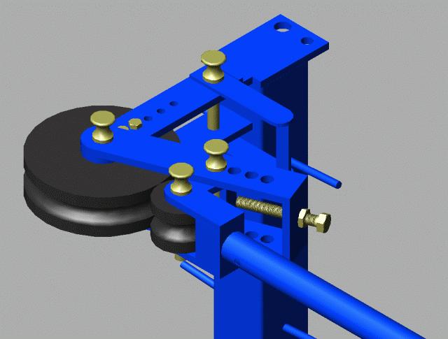
15 Finishing, Assembly And Directions for Use. 1. Thoroughly clean the machine with thinners or turps to remove all traces of oil and anti-spatter fluid. Spray all the metal work with a good quality polyurethane paint, and leave until the paint has hardened. 2. Put a small amount of molybdenum disulphide grease on the end of the M18 hex screw and insert through the hole and into the welded nut in the primary lever. Do not tighten the lock nut yet. 3. Choose whichever size of die set you want to use and put the stop strap over the die arms, and retain it with the Ø18mm pivot pin. 4. Put the bending die in position in the die arms, and secure with the two M12 bolts, Ø12mm washers and M12 nuts. 5. Place the primary lever over the die arms, and wipe a finger full of moly grease around the inside of the holes in the end of the primary lever and die. Wipe some more grease around the Ø24mm pivot pin and drop it into the hole. 6. Similarly, grease the remaining pivot holes and pins, and mount the secondary lever into the primary lever, securing with one of the Ø20mm pivot pins. 7. Place the die roller in the fork of the secondary lever and push its greased pin into position. 8. In use, the die roller should barely come into contact with the die. With the pressures involved, the die components rolling against each other, whether steel, aluminium or acetal, could eventually distort their edges resulting in poor quality bends. Drag caused by the huge pressures would also increase the amount of effort required to pull the handle around. In practice, the aim is to use the hex screw and lock nut in the primary lever to adjust the position of the secondary lever to maintain a virtually unperceivable gap between the roller and die. 9. With the bender now assembled, rotate the die roller a couple of times to distribute the grease. 10. Swing the handle back and insert an appropriate length of tube through the stop arm. The distance from the face of the end piece in the stop arm to the bending die centreline is 225mm, and can therefore be useful as a marker to set up the bend from. 11. It is recommended to make a few trial bends using tube off cuts to familiarise yourself with each size of die set. In each case, check the proximity of the die roller with the die and adjust where necessary.
16
17 Useful Information. CLR = Centre Line Radius DOB = Degree Of Bend Length of tube in a bend = CLR X DOB X or, to put it another way: L = (R X.01745) x Z, L is the length, in inches, R is radius of the pipe bend, Z is the angle of the bend. Setback = radius X tangent ½ angle of bend. Circumference = X diameter. Happy bending! Rorty Design PO Box Law Courts Melbourne VIC 8010 Australia. info@rorty-design.com
18
19
20
21
22
23
24
25
26
27
28
29
ASSEMBLY INSTRUCTIONS FOR MAR-K BEDSIDES AND GM FLUSH TAILGATE WITH HANDLE
 ASSEMBLY INSTRUCTIONS FOR MAR-K BEDSIDES AND 41-53 GM FLUSH TAILGATE WITH HANDLE Build the box assembly according to the MAR-K assembly instructions. When installing the tailgate and latching mechanisms
Bio-Sand Filtration Mould Construction Guidelines
 Bio-Sand Filtration Mould Construction Guidelines Adriaan Mol & Eric Fewster BioSandFilter.org December 19, 2007 Introduction On the following pages, you will find an illustrated construction guide that
Tools: Sharpie, Square, Vise, Hack saw, Ruler, Punch, Hammer, File. 2. Cut the stock Place stock in vise and cut with hack saw
 Purpose: MAKE CATAPULT ARM Step 1 Tools: Sharpie, Square, Vise, Hack saw, Ruler, Punch, Hammer, File Materials: Flat aluminum ½ inch stock (see picture below) Gloves required 1. Pick up the aluminum ½
METAL BENDER OPERATING & MAINTENANCE INSTRUCTIONS Model Nos: CCB1 & CCB2 Part Nos: & CCB2 CCB1
 METAL BENDER Model Nos: CCB1 & CCB2 Part Nos: 7630073 & 7630074 CCB2 CCB1 OPERATING & MAINTENANCE INSTRUCTIONS 1206 1 The Compact Bender allows you to economically make a variety of bends in flat, square,
1. Begin by rolling your window up all the way 2. Remove your door and window handles by unscrewing the flat head set screws behind each handle.
 1. Begin by rolling your window up all the way 2. Remove your door and window handles by unscrewing the flat head set screws behind each handle. 3. Remove the 12 screws that attach the steel interior door
TOOL LIST FOR TAILGATE HIDDEN LATCH & LINK ASSY FOR FORD FLARESIDE TRUCKS
 TOOL LIST FOR TAILGATE HIDDEN LATCH & LINK ASSY FOR 53-87 FORD FLARESIDE TRUCKS Vise Grip Clamps C-clamps Sharpie Marker Ball Peen Hammer Center Punch 3/8 or 1/2 Drill 5/32, 7/32, 9/32, and 3/8 Drill Bits
Kwik-Lock. Installation Instructions. Attention Dealers: Please give this owners manual to the customer when the product is delivered.
 Serving the Truck & Trailer Industry Since 1944 Installation Instructions Attention Dealers: Please give this owners manual to the customer when the product is delivered. Call 800-535-9545 www.aeroindustries.com
The Virgo/Libra Steam Engine
 The Virgo/Libra Steam Engine Congratulations on becoming the owner of a Virgo or Libra Steam Engine. With careful use and maintenance it will give many years of satisfying performance. Contents 1) Notes
Ford Ranger / Bronco II Set Part # Rev B 5-04
 Ford Ranger / Bronco II Set Part # 21008 Rev B 5-04 Step 1: Prior to Installation: A) Fit: Verify the fit of the flares to vehicle. (Some filing, sanding, or cutting may be necessary to ensure proper fit).
HMP-200 BENDER INSTRUCTION SET
 HMP-200 BENDER INSTRUCTION SET HMP-200 BENDER ASEMBLY INSTRUCTIONS STEP 1 STEP 2 BOLT LEFT SIDE PLATE TO BASE AS SHOWN WITH 1/2 x20 HEX BOLT & FLAT WASHER WELD BASE TO PLATE ON EACH SIDE NOTE: OFFSET HOLE
Bio-Sand Filtration Mould Construction Guidelines
 United Kingdom The Shieling, Wreay Carlisle CA4 0RL Tel: +44 (0)1697 47 5369 Mobile: +44 (0) 7739 665 777 Email: info@biosandfilter.org Madagascar Libanona Americain PB 307 Fort Dauphin (614) Tel: +261
Set Part # Rev
 Set Part # 21007 Rev-3 06-06-11 Step 1: Prior to Installation: A) Bushwacker only approves installing the flares according to these written instructions with the hardware provided. WARNING: Failure to
1949 to 1954 Chevrolet Dual Master Cylinder Conversion
 1949 to 1954 Chevrolet Dual Master Cylinder Conversion This document is a one stop shop to getting your brake system updated on your old Chevy. Whether you re going with a disc conversion or just sticking
Classic Roll Tarp. Installation Instructions. Attention Dealers: Please give this owners manual to the customer when the product is delivered.
 Serving the Truck & Trailer Industry Since 1944 Classic Roll Tarp Attention Dealers: Please give this owners manual to the customer when the product is delivered. Call 800-535-9545 www.aeroindustries.com
N. 15th Street, Middlesboro, KY FLIP TARP DUMP BODY INSTALLATION INSTRUCTIONS
 1-800-248-7717 1002 N. 15th Street, Middlesboro, KY 40965 FLIP TARP DUMP BODY INSTALLATION INSTRUCTIONS Congratulations on your purchase of a Mountain Flip Tarp Dump Body tarping system. With tarping systems
FLIP TARP SINGLE & DOUBLE UNDERBODY TRAILERS
 1-800-248-7717 1002 N. 15th Street, Middlesboro, KY 40965 FLIP TARP SINGLE & DOUBLE UNDERBODY TRAILERS INSTALLATION INSTRUCTIONS Congratulations on your purchase of a Mountain Flip Tarp Trailer system.
BEST PRACTICE GUIDE. Socket Bases. Working with Concrete Slabs
 Working with Concrete Slabs When working with concrete slabs the barrier protection can be erected in three ways - with socket bases, adjustable slab edge brackets and multi slab clamps. Socket Bases 1
Model 209 Fireback Replacement
 Model 209 Fireback Replacement Please read all the instructions before you begin the procedure. Confirm that you have all the necessary tools and materials. If you have any questions, technical support
How To Build A Tube Bender by Terry Tasky
 How To Build A Tube Bender by Terry Tasky I would like to thank the good people at Blind Chicken Racing for supplying the basics to make this bender. I have taken their project a step further and have
END FRAMES. End frames built using pressure treated 2x4 (1 1/2" x 3 1/2") 36" 34" 7/16" pilot hole. 5 1/2" x 1/2" lag bolt 8" wheel 23"
 36 34 7/16 pilot hole. 5 1/2 x 1/2 lag bolt 8 wheel 23") END FRAMES End frames built using pressure treated 2x4 (1 1/2" x 3 1/2") 23" 17 1/2" (B) (B) Measure from the bottom of your stone to 1" below the lip to get your measurement. 17 1/2"(B) 36" 34" 1/2" flat
END FRAMES End frames built using pressure treated 2x4 (1 1/2" x 3 1/2") 23" 17 1/2" (B) (B) Measure from the bottom of your stone to 1" below the lip to get your measurement. 17 1/2"(B) 36" 34" 1/2" flat
WPS crew Doors Installation instructions
 WPS-132-133 crew Doors Installation instructions ORDER OF INSTALLATION FOR A COMPLETE ENCLOSURE OF A CREW WPS (Weather Protection System) IS AS FOLLOWS: 1. Heater 2. Rear Thresholds - Right Hand & Left
Assembly Instructions: Bencher Skylark
 Assembly Instructions: Bencher Skylark Tools Required: Pop Rivet Tool Tape Measure Hex Wrenches Screwdriver Several Disposable Rags Two Saw Horses Several boxes or bowls to hold fasteners and small parts
How To Measure Your Finished Opening
 3000 Series Bifold Doors How To Measure Your Finished Opening MEASURE FROM RIGHT TO LEFT 2 PLACES (WIDTH) MEASURE FROM TOP TO BOTTOM 2 PLACES (HEIGHT) Tools Required for Assembly: Tools Needed: Phillips
Classic Roll Tarp. Installation Instructions. Attention Dealers: Please give this owners manual to the customer when the product is delivered.
 Serving the Truck & Trailer Industry Since 1944 Classic Roll Tarp Attention Dealers: Please give this owners manual to the customer when the product is delivered. Call 800-535-9545 www.aeroindustries.com
Jeep. Flat Style Fender Flares Front Pair. Included in Hardware Kit:
 Jeep Flat Style Fender Flares Front Pair STEP 1 PRIOR TO INSTALLATION A) Bushwacker only approves installing the fl ares according to these written instructions with the hardware provided. WARNING: Failure
GlideRite Retractable Cover System For HotSpring & Tiger River Spas (except Classic & pre-2000 Landmark Spas)
") List of Contents Quantity Description 12 #10 x 1 ½ Flat Head Phillips Screw (see pg. 2) 2 #10 x ½ Pan Head Phillips Screw (see pg. 2) 8 ¼ x 2 ½ Lag Bolt (see pg. 2) 7 ¼ 20 x 5 / 8 Hex Head Bolt (see pg.
List of Contents Quantity Description 12 #10 x 1 ½ Flat Head Phillips Screw (see pg. 2) 2 #10 x ½ Pan Head Phillips Screw (see pg. 2) 8 ¼ x 2 ½ Lag Bolt (see pg. 2) 7 ¼ 20 x 5 / 8 Hex Head Bolt (see pg.
# in 1 Metal Worker Auxiliary Operating Instructions
 340 Snyder Avenue, Berkeley Heights, NJ 07922 www.micromark.com MMTechService@micromark.com Tech Support: 908-464-1094, weekdays, 1pm to 5 pm ET #86556 3 in 1 Metal Worker Auxiliary Operating Instructions
Two Panel Frameless Bypass Door
 INSTALLATION INSTRUCTIONS Two Frameless Bypass Door Series 00 Please Record Model Number From Carton Label Here Please read these instructions carefully to familiarize yourself with the required tools,
Toyota FJ Cruiser 2006-Up Set Part # Revision A
 Toyota FJ Cruiser 2006-Up Set Part # 31924 Revision A 03-31-08 Step 1: Prior to Installation: A) Fit: Verify the fit of the flares to vehicle. (Some filing, sanding, or cutting may be necessary to ensure
Clamping devices 521
 Clamping devices 521 522 Product overview Clamping devices Adjustable straps K0001 Hook clamps K0012 Goose-neck straps with long slot K0002 Page 526 Hook Clamps with collar K0013 Page 535 Equipped clamps
Make a Safe. Description. Lesson Objectives. Assumptions. Terminology
 Youth Explore Trades Skills Make a Safe Description Welding is a vast area in the metalworking field and a widely used joining process for metal. In this activity plan students will learn how to MIG weld
Clock 35 - Toyland. Construction instructions for Clock 35
 This clock has been designed for children, it is a stand-alone unit and can be positioned on a shelf or cabinet out of the reach of very young hands who may be tempted to touch. The clock is shown in two
Cut-True 16M Manual Paper Cutter
 Cut-True 16M Manual Paper Cutter 2/2013 OPERATOR MANUAL FIRST EDITION TABLE OF CONTENTS TOPIC PAGE Specifications 1 Safety Guidelines 1 Assembly 2 Overview 3 Description of Equipment Parts 3-4 Operation
HIT-30 ALUMINUM DOOR SERIES OWNERS MANUAL
 HIT-30 ALUMINUM DOOR SERIES OWNERS MANUAL INSTALL LOCKS LATCHES LEVERS / PADDLES INDICATORS STRIKES Every Installation Is A Self-Portrait Of The Person Who Did It! Autograph Your Work With Excellence!
PowerLock. Installation Instructions. Attention Dealers: Please give this owners manual to the customer when the product is delivered.
 Serving the Truck & Trailer Industry Since 1944 PowerLock Attention Dealers: Please give this owners manual to the customer when the product is delivered. Call 800-535-9545 www.aeroindustries.com Indianapolis,
SWAG AIR-HYDRO RAM MOUNT ASSEMBLY INSTRUCTIONS
 SWAG AIR-HYDRO RAM MOUNT ASSEMBLY INSTRUCTIONS Tools needed for assembly: 5/16 HEX KEY WRENCH ¼ HEX KEY WRENCH ¾ SOCKET AND WRENCH 1.125 SOCKET HAMMER FLAT SCREW DRIVER GREASE FOR ASSEMBLY Step #1 Disassemble
6625 WEST WILSHIRE BLVD. OKLAHOMA CITY, OK (405) FAX (405)
 FAX (405)") INSTALLATION INSTRUCTIONS FOR BEDSIDE INNER REPAIR PANELS 67-72 GM FLEETSIDES This instruction illustrates the removal and replacement of the often rusted and damaged lower inner flanges on the 1967-1972
INSTALLATION INSTRUCTIONS FOR BEDSIDE INNER REPAIR PANELS 67-72 GM FLEETSIDES This instruction illustrates the removal and replacement of the often rusted and damaged lower inner flanges on the 1967-1972
PowerLock. Installation Instructions. Attention Dealers: Please give this owners manual to the customer when the product is delivered.
 Serving the Truck & Trailer Industry Since 1944 FOR Attention Dealers: Please give this owners manual to the customer when the product is delivered. Call 800-535-9545 www.aeroindustries.com Indianapolis,
TABLE OF CONTENTS REQUIRED TOOLS
 TABLE OF CONTENTS SECTION SECTION TITLE PAGE NO. 1 2 3 4 5 Assembling Mounting Structure Installing Bicycle Supports Mounting Rack to Wall Adding Sections Customizing Rack Configuration REQUIRED TOOLS
Included in Hardware Kit. Jeep Cut-Out Fender Flare Set of 4 Set Part # Rev STEP 1 PRIOR TO INSTALLATION
 Jeep Cut-Out Fender Flare Set of 4 Set Part #10926-07 Rev-01 09-11-12 STEP 1 PRIOR TO INSTALLATION A) Bushwacker only approves installing the flares according to these written instructions with the hardware
Practical Scrap Metal Small Arms Vol.10 By Professor Parabellum
 Practical Scrap Metal Small Arms Vol.10 By Professor Parabellum Introduction The 9mm submachine gun design described here is extremely basic and can be put together using very limited tools and materials.
AMETAL SHAPER is indispensable for certain METAL SHAPER FOR YOUR SHOP. By S. S. Miner
 METAL SHAPER FOR YOUR SHOP By S. S. Miner AMETAL SHAPER is indispensable for certain machining operations where flat surfaces must be produced within very close limits, such as machining flats on castings,
Assembly Instructions 10 X 10 Aluminum Roof Support
 Assembly Instructions 10 X 10 Aluminum Roof Support Aluminum Roof Support Bolt Package 16-5/16 X 2 ¼ SS Bolt 24-5/16 X 1 SS Bolt 40-5/16 SS Nylon Lock Nuts 16-5/16 SS Flat Washers 28-4 ½ Wood Screws 36-1
Making Simple Bookbinding Equipment
 Tony Firman 20 1 2 19 Notes Tony Firman Tony Firman Bookbinding 18 3 : 2012 Tony Firman Bookbinding P.O. Box 507 Haslet, TX 76052 www.tonyfirmanbookbinding.com 4. When all the tapes have been pinned in
Privacy Wall Glass Selections - Polished Edge Slider Door
 Privacy Wall Glass Selections - Polished Edge Slider Door 3/6" HEX BIT PUTTY KNIFE #2 ACR BIT SUCTION CUP HOLDERS DOOR LEAF: Satin Tempered Clear Tempered LOCTITE 425 SIDE LIGHT ETCHED GLASS STYLES: Satin
Installation for Full Size Polaris Ranger Crew Doors
 Installation for Full Size Polaris Ranger Crew Doors Order of Installation: Heater Doors Wiper on to Windshield Windshield Top & Back Panel Note: Most of the steps in these instructions need to be repeated
Lumber Smith. Assembly Manual. If you are having problems assembling the saw and need assistance, please contact us at:
 Lumber Smith Assembly Manual If you are having problems assembling the saw and need assistance, please contact us at: 804-577-7398 info@lumbersmith.com 1 Step 1 Safety Carefully read the Owners Manual.
4" METAL BENDER INSTRUCTIONS. Part #20521
 4" METAL BENDER INSTRUCTIONS Part #20521 The EASTWOOD 4 METAL BENDER is a high quality, industrial style tool capable of generating a powerful 2-1/2 tons of pressing force to create 90 or lesser repeatable
Jeep Cherokee Door XJ Set Part # Revision J
 Jeep Cherokee 84-96 4 Door XJ Set Part # 10911 Revision J 6-5-06 Step 1: Prior to Installation: A) Fit: Verify the fit of the flares to vehicle. (Some filing, sanding, or cutting may be necessary to ensure
PAN AND BOX BRAKE INSTRUCTIONS. Item #20649
 PAN AND BOX BRAKE INSTRUCTIONS Item #20649 The EASTWOOD 12 & 24 PAN AND BOX BRAKES are precision engineered metal working tools designed to produce accurate, variable length bends in angles up to 135 in
MANUAL DE MONTAJE ASSEMBLY MANUAL AIREADOR DE PLUG AERATOR MODEL # AE-48T. Hardware & Parts Listing Assembly Instructions Maintenance Notes for
 ASSEMBLY MANUAL Hardware & Parts Listing Assembly Instructions Maintenance Notes for 48 PLUG AERATOR MANUAL DE MONTAJE Lista de piezas y tornillería Instrucciones de armado Notas de mantenimiento para
How to Make a Hat Bending Jig
 How to Make a Hat Bending Jig MATERIALS One 2" x 8" x 11" long (Base Block) exact measurements are 7 ½" x 1 ½" x 11" (Pine is OK to use, I have used scrap Walnut for my benders) Four pieces of Oak 1" x
PowerLock. Installation Instructions. Attention Dealers: Please give this owners manual to the customer when the product is delivered.
 Serving the Truck & Trailer Industry Since 1944 FOR Attention Dealers: Please give this owners manual to the customer when the product is delivered. Call 800-535-9545 www.aeroindustries.com Indianapolis,
CUT OUT FLARES INSTALLATION INSTRUCTIONS FOR 20017, 20018, F100-F150 F250-F350 P.U. & BRONCO CUT OUTS
 20017 04/22/03 REV-A CUT OUT FLARES INSTALLATION INSTRUCTIONS FOR 20017, 20018, F100-F150 F250-F350 P.U. & BRONCO CUT OUTS Tools Required for Installation: (A) 3/16 Drill Bit (B) Pop-Rivet Gun (C) Air
Side Winder R o u t e r L i f t.
 Woodpeckers PRECISION WOODWORKING TOOLS Side Winder R o u t e r L i f t. INSTALLATION INSTRUCTIONS The wrench handle must be pointing left in order to fully insert or remove it. Lift Wrench Once fully
Jeep. Flat Style Fender Flares Rear Pair. Included in Hardware Kit:
 Jeep Flat Style Fender Flares Rear Pair STEP 1 PRIOR TO INSTALLATION A) Bushwacker only approves installing the fl ares according to these written instructions with the hardware provided. WARNING: Failure
SE5a Instrument Board part 2 - rev 1.1
 SE5a Instrument Board part 2 - rev 1.1 Fuel (Petrol) Valve This valve uses two circular name plates, eight brass screws, one black plastic base, copper wire and two black plastic risers. You can pick any
Bendarc. Assembly Instructions. <<< Remove 5" pivot. Move the roller to the correct hole for your radius. (use 3/4" wrench)
") Bendarc Assembly Instructions
Bendarc Assembly Instructions
REPAIR INSTRUCTIONS. Cat. No Cat. No MILWAUKEE ELECTRIC TOOL CORPORATION. SDS Max Demolition Hammer. SDS Max Rotary Hammer
 Cat. No. 9-0 SDS Max Demolition Hammer Cat. No. -0 SDS Max Rotary Hammer MILWAUKEE ELECTRIC TOOL CORPORATION W. LISBON ROAD BROOKFIELD, WISCONSIN 00-0 8-9-0 d 000 8-9-0 d Special Tools Require Forcing
JEEP JK ( 5 DOOR ) SLIMLINE II - FULL TRAY EXTREME RACK KIT
 SLIMLINE II - FULL TRAY EXTREME RACK KIT") JEEP JK ( 5 DOOR ) SLIMLINE II - FULL TRAY EXTREME RACK KIT FAJK001 / KRJW014T INSTALL TIME: 2.5 Hours NOTE: Your Jeep JK (5 Door) Extreme Roof Rack Kit consists of four boxes. (1) the Tray, (2) the Roll
JEEP JK ( 5 DOOR ) SLIMLINE II - FULL TRAY EXTREME RACK KIT FAJK001 / KRJW014T INSTALL TIME: 2.5 Hours NOTE: Your Jeep JK (5 Door) Extreme Roof Rack Kit consists of four boxes. (1) the Tray, (2) the Roll
INSTALLATION INSTRUCTIONS 3"/4 BENT END SIDEBARS FORD F-150 SUPERCREW PART # DZ /DZ
 INSTALLATION INSTRUCTIONS 09-12 FORD F-150 SUPERCREW PART # DZ 372697/DZ 372699 PARTS LIST: 1 Driver/Left Sidebar 4 1/2 Lock Washers 1 Sidebar 4 12mm x 32mm OD x 3mm Flat Washers 1 Driver/Left Mounting
1. Turn off or disconnect power to unit (machine). 2. Push IN the release bar on the quick change base plate. Locking latch will pivot downward.
. 2. Push IN the release bar on the quick change base plate. Locking latch will pivot downward.") Figure 1 Miniature Quick Change Applicators, of the end feed type, are designed to crimp end feed strip terminals to prestripped wires. Each applicator is set up to accept the strip form of certain specific
Figure 1 Miniature Quick Change Applicators, of the end feed type, are designed to crimp end feed strip terminals to prestripped wires. Each applicator is set up to accept the strip form of certain specific
Work Space Set-up. Slats will level the pipe during bending and help minimize twisting of the bow.
 Work Space Set-up Affix pipe bender to end of working surface Slats will level the pipe during bending and help minimize twisting of the bow. Make the slat height equal the distance from your work surface
Flat Style Fender Flares Rear Pair. Jeep. Included in Hardware Kit:
 Jeep Flat Style Fender Flares Rear Pair STEP 1 PRIOR TO INSTALLATION A) Bushwacker only approves installing the fl ares according to these written instructions with the hardware provided. WARNING: Failure
Slide the stock rubber tank mount caps onto the ends of the CS-1 tank mount:
 RYCA CS-1 BODY PARTS INSTALLATION GUIDE [The CS-1 installation guides should be used as supplements to the videos found on our Youtube Channel. There is no strict order to the build process, but it is
GlideRite Retractable Cover System For Hot Spot Spas (SE & SLX only)
") List of Contents Quantity Description 12 #10 x 1 ½ Flat Head Phillips Screw (see pg. 2) 2 #10 x ½ Pan Head Phillips Screw (see pg. 2) 8 ¼ x 2 ½ Lag Bolt (see pg. 2) 7 ¼ 20 x 5 / 8 Hex Head Bolt (see pg.
List of Contents Quantity Description 12 #10 x 1 ½ Flat Head Phillips Screw (see pg. 2) 2 #10 x ½ Pan Head Phillips Screw (see pg. 2) 8 ¼ x 2 ½ Lag Bolt (see pg. 2) 7 ¼ 20 x 5 / 8 Hex Head Bolt (see pg.
MODEL 200/220 ASSEMBLY INSTRUCTIONS
 V-Twin MFG. Coats Tire Changer VT Part No. 16-0510 This tool should only be used by a knowledgeable and trained motorcycle technician V-Twin Mfg. accepts no responsibility for improper use. MODEL 200/220
INSTALLATION MANUAL IOWA MOLD TOOLING CO., INC. BOX 189, GARNER, IA MANUAL PART NUMBER:
 PARTS-1 Model 24562/28562 Crane INSTALLATION MANUAL IOWA MOLD TOOLING CO., INC. BOX 189, GARNER, IA 50438-0189 641-923-3711 MANUAL PART NUMBER: 99903701 Iowa Mold Tooling Co., Inc. is an Oshkosh Truck
BUMP GATE FITTING INSTRUCTIONS.
 1 BUMP GATE FITTING INSTRUCTIONS. HEAVY DUTY MODEL FOR STEEL POSTS. Hinge post Lock post Bump arms Two-way lock Thank you for purchasing a Bump Gate. This device will provide you with many years of good
Quick-Release Sliding Tail Vise 05G30.01
 Quick-Release Sliding Tail Vise 05G30.01 U.S. Des. Pat. No. D671,812 U.S. Pat. No. 9,050,710 Introduction The Veritas Quick-Release Sliding Tail Vise is a reworked version of the well-known tail vise that
Jeep Cherokee 4-Door XJ Set Part # Rev
 Jeep Cherokee 4-Door XJ Set Part # 10911 Rev-14 04-05-10 Step 1: Prior to Installation: A) Bushwacker only approves installing the flares according to these written instructions with the hardware provided.
1984 to ZX (Z31) Rear Camber Modification Gary Molitor, March 1, 2009
 Rear Camber Modification Gary Molitor, March 1, 2009") 1984 to 1989 300ZX (Z31) Rear Camber Modification Gary Molitor, March 1, 2009 Step 1: Bushing Removal After removal of the rear suspension and disassembly of all the parts, the first thing I did was remove
1984 to 1989 300ZX (Z31) Rear Camber Modification Gary Molitor, March 1, 2009 Step 1: Bushing Removal After removal of the rear suspension and disassembly of all the parts, the first thing I did was remove
MODEL T28173/T28174 ROLLER TABLES INSTRUCTIONS
 MODEL T28173/T28174 ROLLER TABLES INSTRUCTIONS FOR MODELS MFD. SINCE 10/17 For questions or help with this product contact Tech Support at (570) 546-9663 or techsupport@grizzly.com Rails Rollers Reversible
TIRE RACK INSTALLATION INSTRUCTIONS Dodge Sprinter
 Aluminess Products Inc 9402 Wheatlands Ct. #A Santee, CA 92071 619-449-9930 TIRE RACK INSTALLATION INSTRUCTIONS 07-11 Dodge Sprinter Please read before beginning Stainless steel hardware may bind together
Flex Fence Instruction Manual
 The Safer Stronger Smarter Choice Flex Fence Instruction Manual Table of contents 2 3 4 4 5 5 6 7 8 10 10 11 11 12 13 13 15 18 18 19 20 22 Table of contents Supplies, tools and equipment Introduction Laying
Sheet Metal Tools. by:prem Mahendranathan
 Sheet Metal Tools by: SHEET METAL TOOL KIT SHEET METAL TOOLS Rivet Gun 3/32, 1/8, 5/32, 3/16",Cupped Set Mini Bucking Bar Footed Heel-Toe Bucking Bar Air Tool Oil Mechanics Tool Bag High-Speed Air Drill
i sburgh COMPACT BENDER ASSEMBLY INSTRUCTIONS & PROJECT IDEAS Rev 08/00
 i sburgh COMPACT BENDER 31980 ASSEMBLY INSTRUCTIONS & PROJECT IDEAS 2000 Rev 08/00 THANK YOU for choosing a HARBOR FREIGHT TOOLS product. For future reference, please complete the owner s record below:
Q-Zone Hoop-Frame. Assembly Instructions. Copyright July 11, 2018 Grace Company (Reproduction Prohibited) Version 1.8
 Version 1.8") Q-Zone Hoop-Frame Assembly Instructions Copyright July 11, 2018 Grace Company (Reproduction Prohibited) Version 1.8 Table of Contents Table of Contents... i Warranty... ii Parts List Box 1...iii Box 2...
Q-Zone Hoop-Frame Assembly Instructions Copyright July 11, 2018 Grace Company (Reproduction Prohibited) Version 1.8 Table of Contents Table of Contents... i Warranty... ii Parts List Box 1...iii Box 2...
Track Rack. * Track Racks are not lockable
 The Track Rack s unique staggered, sliding hook design creates the greatest parking efficiency while still providing easy access to any particular bike. When adding or removing a bike to the rack, simply
Precision Steel Car s 100 T Steel Coil Car
 Precision Steel Car s 100 T Steel Coil Car Precision Steel Car www.precisionsteelcar.com info@precisionsteelcar.com Paul Vernon: (513) 571-5739 Revised 4/30/2009 Contents of Kit Main Tube Side Frame 2
400GTO Lubrication Guide
 400GTO Lubrication Guide Lubrication Guidelines for the following equatorial mounting: 400GTO Servo with GTOCP2 or CP3 Controller For other 400 models please review other postings as they become available.
EllisSaw.com. EllisSaw.com P.O. Box Verona, WI
 P.O. Box 9019 Verona, WI 9-019 GENERAL OPERATING & SAFETY INSTRUCTIONS * READ INSTRUCTIONS BEFORE USE * CAUTION: Disconnect power supply cord from power source when doing repair work or changing belt.
MB-105 BENDER INSTRUCTION SET PRO-TOOLS 7616 INDUSTRIAL LANE TAMPA, FLORIDA PHONE FAX
 MB-105 BENDER INSTRUCTION SET PRO-TOOLS 7616 INDUSTRIAL LANE TAMPA, FLORIDA 33637-6715 813-986-9000 PHONE 813-985-6588 FAX ASSEMBLY INSTRUCTIONS IN THE FOLLOWING INSTRUCTIONS WE WILL EXPLAIN THE ASSEMBLY
Plastic Push. 5/16 Hex Head Bolt, 20 pcs. Retainer, 20 pcs. Female Bullet Connector, 4 pcs. Side Refl ex Refl ector, 2 pcs
 A) B) C) D) E) F) G) STEP 1 - PRIOR TO INSTALLATION Bushwacker only approves installing the fl ares according to these written instructions with the hardware provided. WARNING: Failure to install according
Item #28187 EASTWOOD BEAD ROLLER INSTRUCTIONS
 Item #28187 EASTWOOD BEAD ROLLER INSTRUCTIONS The Eastwood Bead Roller is a professional metal fabrication tool for producing strengthening ribs in panels used in creating replacement fl oor pans, fi rewalls,
Frameless Inline Door With Return QCI5263
 INSTALLATION INSTRUCTIONS Frameless Inline Door With Return QCI5263 WALL MOUNT HINGES FRAMELESS DOOR / PANEL / RETURN PANEL QCI5263 REV. 0 Page 1 Certified 06/17/2016 Parts List with wall mount hinges
Oxford Stalls Installation Instructions
 Oxford Stalls Installation Instructions RAMM Horse Fencing and Stalls 13150 Airport Hwy. Swanton, OH 43558-9615 1-800-434-8456 Rev. 8/15/17 Before You Start Typical stall sizes are 10 x 10, 12 x 12 or
TRUE TECHNICAL SERVICE MANUAL - ALL MODELS. DOORS/DRAWERS/LIDS
 DOORS/DRAWERS/LIDS 55 56 NOTES DOORS/DRAWERS/LIDS Swing s 73 74 NOTES INSTALLATION OF A GDM-SWING DOOR Phillips Head Screwdriver (2) - 1/8" Drift Punches (forged) Top Bracket NOTE: It may be necessary
ASSEMBLY GUIDE. Mia Narrow Bookcase
 ASSEMBLY GUIDE Mia Narrow Bookcase Components: Upon unpacking your bookcase from it s delivery box, you should have the pieces shown. Follow the steps on the next pages to assemble your new bookcase. Step
WESTERN PISTOL.22 CALIBER SINGLE SHOT. Entire pamphlet Copyrighted by JACO Designs 1972
 WESTERN PISTOL.22 CALIBER SINGLE SHOT Entire pamphlet Copyrighted by JACO Designs 1972 This pamphlet contains the plans and instructions necessary to construct the Western pistol. This pistol breaks open
Ultra Space Saver American Bicycle Security Company
 The Ultra Space Saver is userfriendly and allows easy access to bikes. It provides convenient space for u-lock security on nearly any bike, including bikes with fenders and fork shocks. The double-sided
600mm COMPOUND MITRE SAW ASSEMBLY INSTRUCTIONS. MODEL NO: MBS600D Part No: GC05/12
 600mm COMPOUND MITRE SAW MODEL NO: MBS600D Part No: 6461516 ASSEMBLY INSTRUCTIONS GC05/12 INTRODUCTION Thank you for purchasing this CLARKE Mitre Saw. Before attempting to use the product, it is essential
P.O. Box 8400 Green Bay, WI (920)
") P.O. Box 8400 Green Bay, WI 54308-8400 (920) 468-2165 Change Notice No. 112 Implemented By: KI-Pembroke Notification By: Scott Vissers Date: 03/15/10 Component Product Title: Series XXI Lateral Filing
P.O. Box 8400 Green Bay, WI 54308-8400 (920) 468-2165 Change Notice No. 112 Implemented By: KI-Pembroke Notification By: Scott Vissers Date: 03/15/10 Component Product Title: Series XXI Lateral Filing
ALL SEASON PATIO COVER
 ALL SEASON PATIO COVER 61 Where the All Season Patio Cover is to be attached to the home, create a level line showing where the top of the mounting rail is to be located. Install each section with the
LMI Bending Machine. Photo 1. Photo 2. Photo 3. Photo 5. Photo 4
 LMI Bending Machine Watch the instructional DVD shipped with the LMI Bending Machine prior to assembling or using it. Note the bending head assembly has been changed since these photos were taken. Operationally
Leafy Greens Spinner Construction Manual
 Leafy Greens Spinner Construction Manual University of Houston Conrad N. Hilton College Food Science Lab Materials list: Base and Armature Approximately 8-1 PVC cut into sections o 3-22.5 o 2-7 o 2-4 o
INSTALLATION INSTRUCTIONS
 INSTALLATION INSTRUCTIONS BUILDERS CHOICE FRAMED Bypass Door Model: L0516 (Tub Height), L0517 (Shower Height) Rev. 09.20.13 INSTALLATION NOTES: Unpack your unit carefully and inspect for freight damage.
RTI TECHNOLOGIES, INC.
 RTI TECHNOLOGIES, INC. BRC500 & BRC550 Arbor/Spindle Mechanism Adjustment & Service Technical Instructions The arbor/spindle mechanism of the BRC500/550 is designed to be robust for long life. Occasionally
Jeep. Flat Style Fender Flares Set of 4. Included in Hardware Kit: STEP 1 PRIOR TO INSTALLATION. Set Part # Rev-3 1/11/2016
 STEP 1 PRIOR TO INSTALLATION A) Bushwacker only approves installing the fl ares according to these written instructions with the hardware provided. WARNING: Failure to install according to these instructions
MINI-LATHE QUICK CHANGE TOOL POST
 MINI-LATHE QUICK CHANGE TOOL POST Cutting and assembly details Machinists should familiarize themselves with the contents of this section before jumping in to the drawings. Many details are described here