HIT-30 ALUMINUM DOOR SERIES OWNERS MANUAL
|
|
|
- Christina Glenn
- 5 years ago
- Views:
Transcription


1 HIT-30 ALUMINUM DOOR SERIES OWNERS MANUAL INSTALL LOCKS LATCHES LEVERS / PADDLES INDICATORS STRIKES Every Installation Is A Self-Portrait Of The Person Who Did It! Autograph Your Work With Excellence! 1825 VIA BURTON ANAHEIM, CA (714) FAX (714) WEBSITE: MAIL@MAJORMFG.COM 1 Copyright 2009 Major Manufacturing
2 TABLE OF CONTENTS PAGE GENERAL ROUTER INFORMATION GENERAL SAFETY INFORMATION.6 INSTALLING LOCKS OR LATCHES.7-14 INSTALLING LOCK MOUNTING BRACKETS INSTALLING ADAMS RITE 4502/4902 LIP STRIKE INSTALLING ADAMS RITE 4501/4901 LIP STRIKE STRIKE CUT OUT FOR ADAMS RITE DEAD BOLT STRIKE CUT OUT FOR ADAMS RITE HOOK BOLT WEB SITE INFORMATION Copyright 2009 Major Manufacturing


3 ROUTER RECOMMENDATIONS Thank you for purchasing our HIT-45 modular installation kit. Please take a minute to become familiar with the system and available options. For aluminum door installation we recommend the use of a commercial router. For operator safety please choose a router that can be switched on/off while both hands always remain on the router handles. We highly recommend a commercial router with a D type handle because this router can be more easily controlled and the on/off switch can be operated with your trigger finger. A router that requires you to take one hand off the handle to operate the on/off switch may be difficult to control and possibly dangerous. D-HANDLE WITH ON/OFF SWITCH 3 Copyright 2009 Major Manufacturing
4 ROUTER and ROUTER BIT RECOMMENDATIONS FOR ALUMINUM DOOR WORK We recommend the use of the Porter Cable model 691 D handle router or any D handle router of commercial duty. Sears Craftsman and Ryobi routers may be used if equipped with our template guides, the factory does not have the correct sizes. The use of our 1/4 down shear single flute router bit (HIT-45RB4) is also recommended for the following reasons: Standard hardware store bits are usually up shear. This pulls aluminum chips into your router. This may result in damage to your router or possibly clog the template guide causing damage. Standard bits are usually two fluted. This provides less space for the aluminum chips to clear. If too fast a cut is used, the aluminum could weld itself to the bit. Our bits are single flute, they have plenty of room for chip clearance. Carbide bits will cut clean, however they are very brittle and are easily broken in aluminum. With care and proper lubrication, our high speed steel bits will route many openings. 4 Copyright 2009 Major Manufacturing


5 ROUTER TEMPLATE GUIDES FOR USE ON ALUMINUM DOORS AND FRAMES HIT-45TG1 3/8 OUTSIDE DIAMETER HIT-45TG5 3/8 OUTSIDE DIAMETER HIT-45TG2 3/8 OUTSIDE DIAMETER Template guides for use on older model Sears Craftsman routers. Shown above is a 3/8 outside diameter guide for use with a 1/4 router bit to cut out aluminum doors and frames. NOTE: Newer model Sears routers use the two piece style template Template guide for use on commercial duty routers including: Porter Cable, DeWalt, and newer model Sears Craftsman. On the left is a 3/8 outside diameter guide for use with a 1/4 router bit to cut out aluminum doors and frames. Template guide for use on Ryobi routers. Shown above is a 3/8 outside diameter guide for use with a 1/4 router bit to cut out aluminum doors and frames. HIT-45RB4 1/4 diameter single flute down shear router bit used to route aluminum doors and frames. 5 Copyright 2009 Major Manufacturing
6 MAKE CERTAIN THAT YOU ARE USING THE CORRECT TEMPLATE FOR THE STRIKE BEING INSTALLED AND YOUR ROUTER HAS A 3/8 OUTSIDE TEMPLATE GUIDE INSTALLED IN THE BASE. GENERAL SAFETY RULES ALWAYS WEAR EYE AND EAR PROTECTION!! Before attempting any installation know how to safely use the power tools involved and how they work. Be sure all bits and cutters are sharp and in good condition and all power cords and extension cords are in good working order and properly grounded. Always make sure the router comes to a COMPLETE STOP before pulling it away from the template. Failure to do so may cause damage to your router template, your work or personal injury. Always route in a CLOCKWISE direction. A counterclockwise direction will cause the router bit to climb in the cut and cause an unstable situation. If you feel you have missed part of the cut, DO NOT BACK UP!! You will be making a clean up pass that will take care of the problem. 6 Copyright 2009 Major Manufacturing
7 INSTRUCTIONS FOR HIT-30 CLAMP FOR ALUMINUM DOOR LOCK INSTALLATIONS WHEN USING POWER TOOLS ALWAYS WEAR EYE AND EAR PROTECTION!! 7 Copyright 2009 Major Manufacturing


8 These are the most important tools that you will use in this installation. Always use eye and ear protection!! Select the proper template for the backset that you are installing. The most popular backsets, 31/32 and 1-1/8 can be installed with a lock indicator or prepped with a lever/ paddle arrangement. Lock templates are fastened to the clamp with x 3/4 allen flat head screws. The faceplate template is held on with x 1/2 allen flat head screws. The backset is engraved between the mounting screws. There is a top and bottom to this clamp, always have the writing on the clamp in the upright position. The first time the HIT-30 is used, it must be centered to the door. Take the time to accurately adjust the centering in this step. Measure from one side of the clamp to the door edge as shown. This measurement must be the same top and bottom, right hand and left hand side. Once centered tighten the two large knobs. 8 Copyright 2009 Major Manufacturing


9 Once tight, use a wrench and tighten the two hex nuts on the left hand side of the router jig. This will lock in the centering, now when used on 1-3/4 aluminum doors the jig will be centered and ready to go. Determine the cylinder height of the lock being installed and secure the HIT-30 clamp and templates onto the door as shown. If you are installing the new lock above an existing lock, be sure to remove the existing lock or any other hardware in the channel. FAILURE TO REMOVE EXISTING LOCKS OR HARDWARE FROM THE DOOR CHANNEL WILL RESULT IN FILLING THEM WITH ALUMINUM ROUTING CHIPS AND JAMMING THE MECHANISM! Your router needs to be equipped with a 3/8 outside diameter template guide mounted in its base. Failure to use a template guide will cause the opening being routed to be too large and may damage your HIT-45 templates or the door. Install a 1/4 diameter aluminum router bit into the router collet and secure tightly. Adjust the router bit so it will route about 1/4 to 3/8 into the door channel. 9 Copyright 2009 Major Manufacturing


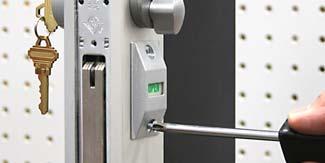
10 Drill a 3/8 or larger starting hole for the router bit in the center of the template hole to be routed. Drill the same starting holes for the faceplate and other lock openings that will be used. Here we are drilling the mounting holes for the lock indicator. They are drilled with a #29 drill bit and will be tapped 8-32 once the router jig is removed from the door. If you are not using an indicator in your installation, do not route the indicator opening or drill these holes. 10 Copyright 2009 Major Manufacturing


11 The two drill bushings, one located above and one below the face plate cutout are for our LMB-033 mounting bracket (radius door) or LMB-034 (bevel door). Drill bushing size is for a #7 drill bit. These mounting brackets are an alternate way of mounting a lock or a must for a deep style door where a bridge will not fit. Countersink after all holes are drilled and routing has been completed and the HIT-30 jig has been removed from the door. Do not drill these holes if using our LMB-08 bracket. The two drill guides located above and below the cylinder hole on this template are for mounting a lever or paddle handle. The drill bushing size is for a #21 drill bit. This hole will be tapped later to to mount a lever handle or re-drilled to a larger size for the factory threaded insert. Do not drill if not installing a paddle or lever. We recommend the area to be routed be lubricated with a cutting lube. We use a product called Tapmatic Edge Cream made by the LPS Company. You can find this product at industrial hardware stores or machine shop supplies. This is also a handy product to use for other drilling or tapping chores. Lube all areas to be routed. 11 Copyright 2009 Major Manufacturing


12 Place the router bit in the starting hole and with firm control of the router follow the HIT-30 template and feed the router slowly in a CLOCKWISE DIRECTION. Make sure the base of the router is held flat on the routing template. We advise routing the cylinder sides of the door first and the faceplate last. When completed with the cut, turn the router off and wait for the bit to come to a complete stop before removing it from the template. Failure to do so may cause damage to the door, your HIT-30 template or injury to yourself. After making the first pass, brush away the chips and make a second clean up pass. Use the same procedure and route the opposite side of the door. Don t forget to brush out the chips and make a second clean up pass. Route the faceplate opening last. When completed, again brush away the chips and make a second pass. We recommend making this cut last because of the unlikely event of a broken router bit, the large faceplate hole will be covered by the router base and the broken bit will most likely be contained in the channel. 12 Copyright 2009 Major Manufacturing


13 Clean the area of left over cutting lube and chips. Use a machinist scraper or an aluminum cutting file and deburr all of the openings. Tap the two indicator mounting holes with a 8-32 tap. Our LMB-08 mounting brackets and LMB-089 tool are being used to mount the lock in the channel. The door can also be drilled and tapped for lock mounting tabs. We do not advise drilling and tapping the rear of the channel like factory doors. They are drilled and tapped prior to the glass being installed, you will be drilling and tapping into a glass channel. You run a great risk of breaking the glass in the door! 13 Copyright 2009 Major Manufacturing


14 LMB-08 brackets in door and lock going in. Complete LMB-08 directions can be seen on page# 16 Secure lock with the screws supplied with the mounting bracket. Alternative method of mounting lock in door shown on next page. 14 Copyright 2009 Major Manufacturing


15 The LMB-033 bracket is double sided. One side has an offset bend, this will mount the lock in a radius door style as shown. The opposite end is used to mount a lock in a radius door style that has a weather strip channel down the center. Leave the mounting screws loose at this step. Once the mounting brackets have been installed and the lock is in the door, tighten all the mounting screws Install the outside cylinder. We recommend the addition of one of our hardened cylinder guards for security. SEE OUR CATALOG OR WEB SITE FOR A COMPLETE LISTING OF CYLINDER GUARDS AND GUARD PLATES. 15 Copyright 2009 Major Manufacturing


16 Inside thumb turn being installed. Lock indicator going in, be sure to install per manufacturers directions. Install the faceplate and the lock is installed. That s all there is to it!!! 16 Copyright 2009 Major Manufacturing
17 INSTRUCTIONS FOR USE WITH LMB-089 TOOL INSTALLING LMB-08 LOCK BRACKETS IN ALUMINUM DOORS 17 Copyright 2009 Major Manufacturing
18 INSTRUCTIONS FOR USE WITH LMB-089 INSTALLATION TOOL FOR LMB-08 BRACKET LMB-08 MOUNTING BRACKET AND ADAPTERS The LMB-08 mounting bracket will conform to three types of door channel. The standard LMB-08 with no adapters is made to fit radius frames. For beveled or flat frames use the supplied adapters as shown. The adapters are mounted on the ears of the mounting bracket. PLASTIC STRIP The plastic adapters shown at the right will snap on the ears of the LMB-08 mounting bracket and adapt it to different door types. To mount the adapters properly, make sure that the number on the top of the adapter is right side up when facing the plastic strip on the mounting bracket. 18 Copyright 2009 Major Manufacturing


19 LMB-089 Mounting bracket installation tool. ATTACH MOUNTING BRACKETS TO LMB-089 INSTALLATION TOOL Using the 8-32 x 1/2 Phillips screws that were supplied, loosely attach a bracket to each side of the tool as shown in the picture. The mounting brackets should be able to spin freely. The knob on the tool should be parallel with the tools length PLACE BRACKETS IN DOOR With both brackets attached to the tool and also parallel to the tools length, slide into the door. The mounting bracket has three holes on the top of the plate. One for mounting the lock and two for holding the bracket in the door. One side of the bracket has a plastic strip securing the top plate to the base. Turn one bracket 90 degrees so the plastic strip points away from the tool. Push the knob down and turn 90 degrees, then slide it towards the bracket until it snaps in place. Now slide the entire tool and bracket to one end of the lock cut out until the tool stops. 19 Copyright 2009 Major Manufacturing
20 SQUARE BRACKETS IN DOOR Lightly tighten the Phillips mounting screw, this will square the bracket in the door. SECURE BRACKETS IN DOOR With the supplied 7/64 ball tip allen wrench, turn the two allen screws counter clockwise until tight. NOTE: OVER TIGHTENING THESE SCREWS WILL DISTORT THE BRACKET. Remove the Phillips screw and mount the other bracket in the same manner. Save the screws and use them to mount the lock in the door frame. First bracket mounted in door. MOUNT SECOND BRACKET Remove the Phillips screw and mount the other bracket in the same manner. Save the screws and use them to mount the lock in the door frame. 20 Copyright 2009 Major Manufacturing


21 Top mounting bracket plastic strip is facing UP. BOTH MOUNTING BRACKETS INSTALLED Both mounting brackets are now installed in door frame. Note position of plastic strip, if brackets are mounted upside down, the hole spacing will be off. Bottom mounting bracket plastic strip is facing DOWN. Insert lock in door. Secure lock in door using screws supplied with brackets. Installation is complete. Add lock cylinders and faceplate. 21 Copyright 2009 Major Manufacturing


22 The following pages show strike installations only. The HIT-30 is NOT Required 22 Copyright 2009 Major Manufacturing
23 INSTRUCTIONS FOR HIT-40AR3 ADAMS RITE 4502/4902 SERIES LIP STRIKE TEMPLATE WHEN USING POWER TOOLS ALWAYS WEAR EYE AND EAR PROTECTION!! 23 Copyright 2009 Major Manufacturing
24 These are the most important tools that you will use in this installation. Always use eye and ear protection!! Your router needs to be equipped with a 3/8 outside diameter template guide mounted in its base. Failure to use a template guide will cause the opening being routed to be too large and will damage your HIT-40 template. See our catalog or web site for a list of available router template guides. Install a 1/4 diameter aluminum router bit into the router collet and secure tightly. Adjust the router bit so it will route about 1/4 to 3/8 into the door channel. 24 Copyright 2009 Major Manufacturing


25 For height alignment, close the door until the latch makes contact with the door jamb. Use a pencil and mark the top and bottom of the latch. Use a combination square and transfer the lines on the front edge of the door to the side. This will show the location of the latch when it is in the locked position. Find the center line of the jamb. This example shows the center line on a 4 wide offset hung door. The center line is 7/8 from the stop, or one half the thickness of the door. Use a combination square and draw a vertical line at this point. 25 Copyright 2009 Major Manufacturing


26 Pencil lines showing the center line of the jamb and the height of the bolt when locked have been established. Use the alignment marks on the template to align with the pencil lines on the jamb. We will route the strike opening with our HIT-40AR3 template. Attach to jamb with the supplied tek point screws and an electric drill. NOTE: It is a good idea that your drill is equipped with a clutch feature, this will prevent snapping the screw off in the jamb. Make sure the template is square to the jamb prior to running the second screw in. Template mounted and ready to go. 26 Copyright 2009 Major Manufacturing


27 Drill a 3/8 or larger starting hole for the router bit in the center of the template hole to be routed. In the picture we are using a step drill bit. We recommend the area to be routed be lubricated with a cutting lube. We use a product called Tapmatic Edge Cream made by the LPS Company. You can find this product at industrial hardware stores or machine shop supplies. This is also a handy product to use for other drilling or tapping chores. Place the router bit in the center of the starting hole. 27 Copyright 2009 Major Manufacturing


28 Place the router bit in the starting hole and with firm control of the router follow the HIT-40 template and feed the router slowly in a CLOCKWISE DIRECTION. Route in a line up the front portion of the jamb staying just inside the frame to complete the opening. ( If you route out the front of the frame at this point, there will be a large gap in front of the strike that will be visible. ) This area will be routed out after the bit has been adjusted to a new cutting depth. IMPORTANT!! DO NOT ROUTE THROUGH THE FRONT EDGE OF THE JAMB. MAKE THE VERTICLE CUT ABOUT 3/8 INSIDE THE FRONT EDGE. Make sure the base of the router is held flat on the routing template. When completed with the cut, turn the router off and wait for the bit to come to a complete stop before removing it from the template. Failure to do so may cause damage to the door, your HIT-40 template, or injury to yourself. This is the area you did not cut through in the step above. Adjust the depth of the router to cut the thickness of the jamb material only, this should be a cut depth of only about 1/8 inch. Use the router to nibble away this area. 28 Copyright 2009 Major Manufacturing


29 Remove the router template, clean off the lube and de-burr the sharp edges with scraper or file. Drill out the holes left by the tek screws to 3/16. These holes will be used to mount the factory mounting bracket. Counter sink both holes for the flat head mounting screws supplied by the factory. 29 Copyright 2009 Major Manufacturing


30 Factory mounting bracket being installed. Finished installation showing strike and dust box. That s all there is to it!! 30 Copyright 2009 Major Manufacturing
31 INSTRUCTIONS FOR HIT-40AR4 ADAMS RITE 4501/4901 SERIES LIP STRIKE TEMPLATE WHEN USING POWER TOOLS ALWAYS WEAR EYE AND EAR PROTECTION!! 31 Copyright 2009 Major Manufacturing
32 These are the most important tools that you will use in this installation. Always use eye and ear protection!! Your router needs to be equipped with a 3/8 outside diameter template guide mounted in its base. Failure to use a template guide will cause the opening being routed to be too large and will damage your HIT-40 template. See our catalog or web site for a list of available router template guides. Install a 1/4 diameter aluminum router bit into the router collet and secure tightly. Adjust the router bit so it will route about 1/4 to 3/8 into the door channel. 32 Copyright 2009 Major Manufacturing


33 The Adams Rite 4501/4901 strike plate was designed to fill the opening of a deadbolt lock when retrofitting to a deadlatch style lock. The strike plate has two openings. Only one will be used depending on the hand of the door, the other will be filled by the black plastic dust cover. 33 Copyright 2009 Major Manufacturing


34 For height alignment, close the door until the latch makes contact with the door jamb. Use a pencil and mark the top and bottom of the latch. Use a combination square and transfer the lines on the front edge of the door to the side. This will show the location of the latch when it is in the locked position. Find the center line of the jamb. This example shows the center line on an offset hung door. The center line is 7/8 from the stop, or one half the thickness of the door. Use a combination square and draw a vertical line at this point. 34 Copyright 2009 Major Manufacturing


35 Pencil lines showing the center line of the jamb and the height of the latch when locked have been established. Use the alignment marks on the template to align with the pencil lines on the jamb. Use the two lines on the top of the template. DO NOT USE THE TWO CENTER LINES. We will route the strike opening with our HIT-40AR4 template. Attach to jamb with the supplied tek point screws and an electric drill. NOTE: It is a good idea that your drill is equipped with a clutch feature, this will prevent snapping the screw off in the jamb. Make sure the template is square to the jamb prior to running the second screw in. Template mounted and ready to go. We recommend the area to be routed be lubricated with a cutting lube. We use a product called Tapmatic Edge Cream made by the LPS Company. You can find this product at industrial hardware stores or machine shop supplies. This is also a handy product to use for other drilling or tapping chores. 35 Copyright 2009 Major Manufacturing


 This area will be routed out after the bit has been adjusted to a new cutting depth. IMPORTANT!")

36 You are now ready to route the new opening. Place the router bit in the existing cut out and with firm control of the router follow the HIT-40 template and feed the router slowly in a CLOCKWISE DIRECTION. Route in a line up the front portion of the jamb staying just inside the frame to complete the opening. ( If you route out the front of the frame at this point, there will be a large gap in front of the strike that will be visible. ) This area will be routed out after the bit has been adjusted to a new cutting depth. IMPORTANT!! DO NOT ROUTE THROUGH THE FRONT EDGE OF THE JAMB. MAKE THE VERTICLE CUT ABOUT 3/8 INSIDE THE FRONT EDGE. Make sure the base of the router is held flat on the routing template. When completed with the cut, turn the router off and wait for the bit to come to a complete stop before removing it from the template. Failure to do so may cause damage to the door, your HIT-40 template, or injury to yourself. 36 Copyright 2009 Major Manufacturing


37 This is the area you did not cut through in the step above. Adjust the depth of the router to cut the thickness of the jamb material only, this should be a cut depth of only about 1/8 inch. Use the router to nibble away this area. Remove the router template, clean off the lube and de-burr the sharp edges with a scraper or a file. Drill out the holes left by the tek screws to 3/16. These holes will be used to mount the factory mounting bracket. 37 Copyright 2009 Major Manufacturing


38 Counter sink the top and bottom holes for flat head screws. Mounting bracket inside opening and first screw being installed. Factory bracket installed. 38 Copyright 2009 Major Manufacturing


39 Black plastic dust box installed in mounting bracket. Install strike plate using factory supplied flat head screws. Completed installation. That s all there is to it! 39 Copyright 2009 Major Manufacturing
40 INSTRUCTIONS FOR HIT-40AR5 STRIKE TEMPLATE FOR AR DEAD BOLT WHEN USING POWER TOOLS ALWAYS WEAR EYE AND EAR PROTECTION!! 40 Copyright 2009 Major Manufacturing
41 These are the most important tools that you will use in this installation. Always use eye and ear protection!! Your router needs to be equipped with a 3/8 outside diameter template guide mounted in its base. Failure to use a template guide will cause the opening being routed to be too large and will damage your HIT-40 template. See our catalog or web site for a list of available router template guides. Install a 1/4 diameter aluminum router bit into the router collet and secure tightly. Adjust the router bit so it will route about 1/4 to 3/8 into the door channel. 41 Copyright 2009 Major Manufacturing


42 For height alignment, throw the bolt and close the door until it makes contact with the door jamb. Use a pencil and mark the top and bottom of the bolt. Use a combination square and transfer the lines on the front edge of the door to the side. This will show the location of the bolt when it is in the locked position. Find the center line of the jamb. This example shows the center line on a 4 wide center hung door. The center line is 2. Use a combination square and draw a vertical line at this point. Note: The center line on an offset hung door will be half the distance from the door stop to the outside of the jamb. 42 Copyright 2009 Major Manufacturing


43 Pencil lines showing the center line of the jamb and the height of the bolt when locked have been established. We will route the strike opening with our HIT-40AR5 template. Use the alignment marks on the template to align with the pencil lines on the jamb. Attach to jamb with the supplied tek point screws and an electric drill. Make sure the template is square to the jamb prior to running the second screw in. NOTE: It is a good idea that your drill is equipped with a clutch feature, this will prevent snapping the screw off in the jamb. Template mounted and ready to go. 43 Copyright 2009 Major Manufacturing


44 Drill a 3/8 or larger starting hole for the router bit in the center of the template hole to be routed. In the picture we are using a step drill bit. We recommend the area to be routed be lubricated with a cutting lube. We use a product called Tapmatic Edge Cream made by the LPS Company. You can find this product at industrial hardware stores or machine shop supplies. This is also a handy product to use for other drilling or tapping chores. Place the router bit in the center of the starting hole. 44 Copyright 2009 Major Manufacturing


45 Place the router bit in the starting hole and with firm control of the router follow the HIT-40 template and feed the router slowly in a CLOCKWISE DIRECTION. Make sure the base of the router is held flat on the routing template. When completed with the cut, turn the router off and wait for the bit to come to a complete stop before removing it from the template. Failure to do so may cause damage to the door, your HIT-40 template or injury to yourself. After making the first pass, brush away the chips and make a second clean up pass. Clean the area of left over cutting lube and chips. Use a machinist scraper or an aluminum cutting file and deburr all of the openings. The two small template mounting holes left by the tek screws can be left as is. Or can be drilled out to 1/8 and filled with a steel pop rivet. 45 Copyright 2009 Major Manufacturing


46 Installing a pop rivet. Finished installation showing mounting holes filled with a pop rivet. That s all there is to it!! 46 Copyright 2009 Major Manufacturing
47 INSTRUCTIONS FOR HIT-40AR6 STRIKE TEMPLATE FOR AR HOOK BOLT WHEN USING POWER TOOLS ALWAYS WEAR EYE AND EAR PROTECTION!! 47 Copyright 2009 Major Manufacturing

48 These are the most important tools that you will use in this installation. Always use eye and ear protection!! Your router needs to be equipped with a 3/8 outside diameter template guide mounted in its base. Failure to use a template guide will cause the opening being routed to be too large and will damage your HIT-40 template. See our catalog or web site for a list of available router template guides. Install a 1/4 diameter aluminum router bit into the router collet and secure tightly. Adjust the router bit so it will route about 1/4 to 3/8 into the door channel. 48 Copyright 2009 Major Manufacturing


49 For height alignment, throw the bolt and close the door until it makes contact with the door jamb. Use a pencil and mark the top and bottom of the hook bolt. Mark the hook area of the bolt as shown. Use a combination square and transfer the lines on the front edge of the door to the side. This will show the location of the bolt when it is in the locked position. Find the center line of the jamb. This example shows the center line on a 4 wide center hung door. The center line is 2. Use a combination square and draw a vertical line at this point. Note: The center line on an offset hung door will be half the distance from the door stop to the outside of the jamb. 49 Copyright 2009 Major Manufacturing


50 Pencil lines showing the center line of the jamb and the height of the bolt when locked have been established. We will route the strike opening with our HIT-40AR6 template. Use the alignment marks on the template to align with the pencil lines on the jamb. Attach to jamb with the supplied tek point screws and an electric drill. Make sure the template is square to the jamb prior to running the second screw in. NOTE: It is a good idea that your drill is equipped with a clutch feature, this will prevent snapping the screw off in the jamb. Template mounted and ready to go. 50 Copyright 2009 Major Manufacturing


51 Drill a 3/8 or larger starting hole for the router bit in the center of the template hole to be routed. In the picture we are using a step drill bit. We recommend the area to be routed be lubricated with a cutting lube. We use a product called Tapmatic Edge Cream made by the LPS Company. You can find this product at industrial hardware stores or machine shop supplies. This is also a handy product to use for other drilling or tapping chores. Place the router bit in the center of the starting hole. 51 Copyright 2009 Major Manufacturing


52 Place the router bit in the starting hole and with firm control of the router follow the HIT-40 template and feed the router slowly in a CLOCKWISE DIRECTION. Make sure the base of the router is held flat on the routing template. When completed with the cut, turn the router off and wait for the bit to come to a complete stop before removing it from the template. Failure to do so may cause damage to the door, your HIT-40 template or injury to yourself. After making the first pass, brush away the chips and make a second clean up pass. Clean the area of left over cutting lube and chips. Use a machinist scraper or an aluminum cutting file and deburr all of the openings. The two small template mounting holes left by the tek screws can be left as is. Or can be drilled out to 1/8 and filled with a steel pop rivet. 52 Copyright 2009 Major Manufacturing


53 Installing a pop rivet. Finished installation showing mounting holes filled with a pop rivet. That s all there is to it! 53 Copyright 2009 Major Manufacturing
54 Visit our web site at: for more information or router recommendations, template guides and other templates to make your installations easier and faster. While there sign up for our newsletter and we will new product information directly to you. 54 Copyright 2009 Major Manufacturing
INSTRUCTIONS FOR HIT-41 SERIES ELECTRIC STRIKE TEMPLATES WHEN USING POWER TOOLS ALWAYS WEAR EYE AND EAR PROTECTION!!
 1825 VIA BURTON ANAHEIM CA 92806 714-772-5202 / FAX 714-772-2302 EMAIL: MAIL@MAJORMFG.COM WEB: WWW.MAJORMFG.COM INSTRUCTIONS FOR HIT-41 SERIES ELECTRIC STRIKE TEMPLATES WHEN USING POWER TOOLS ALWAYS WEAR
WOOD DOOR INSTALLATION
 1825 VIA BURTON ANAHEIM CA 92806 714-772-5202 / FAX 714-772-2302 EMAIL: MAIL@MAJORMFG.COM WEB: WWW.MAJORMFG.COM INSTRUCTIONS FOR HIT-32VD9W TEMPLATE FOR VON DUPRIN 99 RIM WOOD DOOR INSTALLATION WHEN USING
INSTRUCTIONS FOR HIT TEMPLATE FOR SALTO XS-4 MORTISE & CYLINDRICAL LOCKS
 1825 VIA BURTON ANAHEIM CA 92806 714-772-5202 / FAX 714-772-2302 EMAIL: MAIL@MAJORMFG.COM WEB: WWW.MAJORMFG.COM INSTRUCTIONS FOR HIT-66-268 TEMPLATE FOR SALTO XS-4 MORTISE & CYLINDRICAL LOCKS WHEN USING
INSTRUCTIONS FOR HIT TEMPLATE FOR CYLINDRICAL LOCK PREPS
 1825 VIA BURTON ANAHEIM CA 92806 714-772-5202 / FAX 714-772-2302 EMAIL: MAIL@MAJORMFG.COM WEB: WWW.MAJORMFG.COM INSTRUCTIONS FOR HIT-66-110 TEMPLATE FOR CYLINDRICAL LOCK PREPS WHEN USING POWER TOOLS ALWAYS
INSTRUCTIONS FOR HIT TEMPLATE FOR SCHLAGE AD MORTISE LOCK
 1825 VIA BURTON ANAHEIM CA 92806 714-772-5202 / FAX 714-772-2302 EMAIL: MAIL@MAJORMFG.COM WEB: WWW.MAJORMFG.COM INSTRUCTIONS FOR HIT-66-280 TEMPLATE FOR SCHLAGE AD MORTISE LOCK WHEN USING POWER TOOLS ALWAYS
INSTRUCTIONS FOR HIT TEMPLATE FOR ALARM LOCK DL3500 MORTISE LOCK
 1825 VIA BURTON ANAHEIM CA 92806 714-772-5202 / FAX 714-772-2302 EMAIL: MAIL@MAJORMFG.COM WEB: WWW.MAJORMFG.COM INSTRUCTIONS FOR HIT-66-210 TEMPLATE FOR ALARM LOCK DL3500 MORTISE LOCK WHEN USING POWER
INSTRUCTIONS FOR HIT TEMPLATE FOR BEST 34H-37H MORTISE LOCK
 1825 VIA BURTON ANAHEIM CA 92806 714-772-5202 / FAX 714-772-2302 EMAIL: MAIL@MAJORMFG.COM WEB: WWW.MAJORMFG.COM INSTRUCTIONS FOR HIT-66-230 TEMPLATE FOR BEST 34H-37H MORTISE LOCK WHEN USING POWER TOOLS
INSTRUCTIONS FOR HIT LOCK MORTISER
 1825 VIA BURTON ANAHEIM CA 92806 714-772-5202 / FAX 714-772-2302 EMAIL: MAIL@MAJORMFG.COM WEB: WWW.MAJORMFG.COM INSTRUCTIONS FOR HIT-66-200 LOCK MORTISER WHEN USING POWER TOOLS ALWAYS WEAR EYE AND EAR
INSTRUCTIONS FOR HIT TEMPLATE FOR SARGENT MORTISE LOCKS
 1825 VIA BURTON ANAHEIM CA 92806 714-772-5202 / FAX 714-772-2302 EMAIL: MAIL@MAJORMFG.COM WEB: WWW.MAJORMFG.COM INSTRUCTIONS FOR HIT-66-272 TEMPLATE FOR SARGENT MORTISE LOCKS WHEN USING POWER TOOLS ALWAYS
INSTRUCTIONS FOR HIT-45 MORTISE LOCK INSTALLATION
 1825 VIA BURTON ANAHEIM CA 92806 714-772-5202 / FAX 714-772-2302 EMAIL: MAIL@MAJORMFG.COM WEB: WWW.MAJORMFG.COM INSTRUCTIONS FOR HIT-45 MORTISE LOCK INSTALLATION WHEN USING POWER TOOLS ALWAYS WEAR EYE
Safety glasses Measuring tape Level Pencil Power drill Center punch Phillips screw driver Saw horse
 EX76 Concealed Vertical Rod Exit Device Preparation Guide and Installation Instructions Box Contents EX76 Concealed Vertical Rod Exit Device Back Bar Active Push Bar Filler Plate Door Kit with Templates
ED1300/1300F SERIES CONCEALED VERTICAL ROD DEVICE INSTALLATION INSTRUCTIONS
 ED1300/1300F SERIES CONCEALED VERTICAL ROD DEVICE INSTALLATION INSTRUCTIONS Ver.2 1300 SERIES CONCEALED VERTICAL ROD DEVICE Top Strike Latch Screws Strike Screws Release Plunger Top Latch Plunger Screws
INSTALLATION INSTRUCTIONS FOR INSTALLING T-SERIES EXTRA HEAVY DUTY LEVER LOCKSET
 HIGH EDGE 2 1/4"(57mm) 03079400070 INSTALLATION INSTRUCTIONS FOR INSTALLING T-SERIES EXTRA HEAVY DUTY LEVER LOCKSET IMPORTANT: THIS LOCK IS NON-HANDED. LOCK IS FACTORY PACKED PREADJUSTED FOR 1³ ₄" (45mm)
4600 Series Rim Narrow Stile Exit Device Installation Instructions I-ED01162
 DEVICES COVERED IN THIS DOCUMENT: 4600 Series Rim Panic Narrow Stile Exit Device 4600 Series Rim Fire Narrow Stile Exit Device OVERVIEW Outside of Door RHR LHR Inside of Door APPLICATIONS 4950 BLADE STOP
OPERATOR'S MANUAL ROUTER MOUNTING KIT
 OPERATOR'S MANUAL MOUNTING KIT 4950301 (FOR USE WITH BT3000 AND BT3100 TABLE SAWS) Your new router mounting kit has been engineered and manufactured to Ryobi's high standard for dependability, ease of
Shepherd 210A Fingerprint Door Lock Installation Manual V1.1
 Shepherd 210A Fingerprint Door Lock Installation Manual V1.1 Hongda USA Inc. 2505 Technology Dr. #2-6A, Hayward, CA 94545, USA Phone: (510) 887-5682 Fax: (510) 372-0487 Email: info@hongdausa.com Website:
Installing Your Electronic Deadbolt
 Ultra Security Plus Electronic Deadbolt Installation Instructions http://www.hberger.com/video-gallery/electronic-deadbolt New Installation Lock Location Preparation (Skip this section if you door has
For installation assistance, contact SARGENT at DOORS SHOWN HERE SWING IN FOR ILLUSTRATION PURPOSES ONLY.
 SARGENT Installation Instructions for LP8600 x LR8600 & 12-LP8600 x 12-LR8600 Series Low Profile Panic and Fire Exit Devices on Double Egress & Double Doors or LS8600 & 12-LS8600 Low Profile Exit Device
Privacy Wall Glass Selections - Polished Edge Slider Door
 Privacy Wall Glass Selections - Polished Edge Slider Door 3/6" HEX BIT PUTTY KNIFE #2 ACR BIT SUCTION CUP HOLDERS DOOR LEAF: Satin Tempered Clear Tempered LOCTITE 425 SIDE LIGHT ETCHED GLASS STYLES: Satin
Hardware and Components:
 Hardware and Components: (A) 5/16 x 2 Hex Bolt (B) 5/16 x 2-1/4 Hex Bolt (C) 5/16 x 2-1/2 Hex Bolt (D) 4X 5/16 x 3/4 Hex Bolt (E) 4X 5/16 x 1-1/4 Hex Bolt (F) 11X 5/16 Flat Washer (G) 12X 5/16 Nylock Nut
Agricultural Mechanics and Technology Power Tool Safety Rules
 Agricultural Mechanics and Technology Power Tool Safety Rules Name: BAND SAW Use: Cutting curves, circles and irregular shapes. 1. Use clean SHARP blades. 2. The teeth should always point DOWN. 3. Adjust
Lumber Smith. Assembly Manual. If you are having problems assembling the saw and need assistance, please contact us at:
 Lumber Smith Assembly Manual If you are having problems assembling the saw and need assistance, please contact us at: 804-577-7398 info@lumbersmith.com 1 Step 1 Safety Carefully read the Owners Manual.
Hardware and Components:
 Hardware and Components: (A) 4X 5/16 x 1 Carriage Bolt (B) 2X 5/16 x 2-1/4 Carriage Bolt (C) 2X 5/16 x 3-1/4 Hex Bolt (D) 2X 5/16 x 3/4 Hex Bolt (E) 2X 5/16 x 1-1/4 Hex Bolt (F) 5/16 x 2-1/4 Hex Bolt (G)
TOOL LIST FOR TAILGATE HIDDEN LATCH & LINK ASSY FOR FORD FLARESIDE TRUCKS
 TOOL LIST FOR TAILGATE HIDDEN LATCH & LINK ASSY FOR 53-87 FORD FLARESIDE TRUCKS Vise Grip Clamps C-clamps Sharpie Marker Ball Peen Hammer Center Punch 3/8 or 1/2 Drill 5/32, 7/32, 9/32, and 3/8 Drill Bits
OPERATOR'S MANUAL RULES FOR SAFE OPERATION
 OPERATOR'S MANUAL #4950300 ROUTER AND JIG SAW MOUNTING KIT (FOR USE WITH THE BT3000 TABLE SAW) CONGRATULATIONS AND THANK YOU FOR BUYING THIS RYOBI ROUTER AND JIG SAW MOUNTING KIT. Your new #4950300 Router
Entry Mortise Handleset
 1. Pencil 2. No. 2 and No. 3 Phillips Head Screwdrivers 3. No. 1 and No. 2 Slotted Screw Drivers 4. 1/8" Allen Head Wrench 5. 3/4" Wood Chisel or Corner Chisel 6. Measuring Device 7. Lock Mortising Tool
RH-412 STEEL DOORS INSTALLATION INSTRUCTIONS
 RH-412 STEEL DOORS INSTALLATION INSTRUCTIONS By following the steps outlined below, the assembly, installation and adjustment of the steel doors, will be a simple process. Let s start with the Driver Side.
7130(F) Series Mortise Exit Devices Installation Instructions
 Series Mortise Exit Devices Installation Instructions") 7130(F) Series Mortise Exit Devices Installation Instructions Outside Trim Device is packed ready for any Yale 650F or 660F Series Trim. End Clamp (3) 8-32 x 5/16" PUFHMS End Cap (2) 1/4-20 x 1" PPHMS
7130(F) Series Mortise Exit Devices Installation Instructions Outside Trim Device is packed ready for any Yale 650F or 660F Series Trim. End Clamp (3) 8-32 x 5/16" PUFHMS End Cap (2) 1/4-20 x 1" PPHMS
INSTALLING YOUR NEW SPRING LIFT ARM KIT
 INSTALLING YOUR NEW SPRING LIFT ARM KIT 1. Measure the distance that the roof is to be raised. [If your lift system is completely non-functional, you will need to calculate or estimate this distance as
Assembly Instructions 10 X 10 Aluminum Frame Building
 Assembly Instructions 10 X 10 Aluminum Frame Building 27 97 9 8 47 36 74 52 10 10 X 10 Square Building W/ Dome Includes: The Steel Entry Door with a Dead Bolt Lock assembly and Aluminum Door Frame. Metal
Extendable Large Dovetail Jig
 Extendable Large Dovetail Jig Instruction Manual Part # 3458 CAUTION: Please read, understand, and follow all manufacturers instructions, guidelines and owners manuals that come with your power tools.
Tools: Sharpie, Square, Vise, Hack saw, Ruler, Punch, Hammer, File. 2. Cut the stock Place stock in vise and cut with hack saw
 Purpose: MAKE CATAPULT ARM Step 1 Tools: Sharpie, Square, Vise, Hack saw, Ruler, Punch, Hammer, File Materials: Flat aluminum ½ inch stock (see picture below) Gloves required 1. Pick up the aluminum ½
1530(F) Mortise Exit Devices Installation Instructions
 Mortise Exit Devices Installation Instructions") 1530(F) Mortise Exit Devices Installation Instructions Singe Doors or Pairs (2) 12-12-24 PFHUM/WS 798 Universal Strike Standard Device Package Devices are packed ready for application reinforced metal
1530(F) Mortise Exit Devices Installation Instructions Singe Doors or Pairs (2) 12-12-24 PFHUM/WS 798 Universal Strike Standard Device Package Devices are packed ready for application reinforced metal
Stage 2: Preparing the door (read in conjunction with Hole Drilling Options on back of Template).
.") There are three stages to fitting the CL100 mortise case: Stage 1: Marking out the position of the lock. Stage 2: Preparing the door by mortising and drilling holes. Stage 3: Fitting lock, door furniture,
There are three stages to fitting the CL100 mortise case: Stage 1: Marking out the position of the lock. Stage 2: Preparing the door by mortising and drilling holes. Stage 3: Fitting lock, door furniture,
INSTALLATION INSTRUCTIONS REPLACING EXISTING DEADBOLT ASSEMBLY
 INSTALLATION INSTRUCTIONS REPLACING EXISTING DEADBOLT ASSEMBLY A B C L M N D E F G O P Q H I J Tools provided in Amesbury installation kit: (A) door router fixture, (B) doorframe router fixture, (C) ½
98/9927. Devices covered by these instructions: Surface Vertical Rod Exit Device
 911375-00 Surface Vertical Rod Exit Device 98/9927 Installation Instructions Devices covered by these instructions: 98/9927 Surface Vertical Rod Exit Device 98/9927-F (Fire) Surface Vertical Rod Exit Device
Installation Instructions
 VON DUPRIN Installation Instructions 98/9947WDC Concealed Vertical Rod Exit Device Wood Door Applications Devices covered by these instructions: 98/9947WDC Concealed Vertical Rod Device 98/9947WDC-F (Fire)
Heavy Duty Ceiling Tilt Mount Installation Manual
 HD-CTM-5580 Heavy Duty Ceiling Tilt Mount Installation Manual *This Installation requires a minimum of two people. For your safety: Read the complete instruction manual before starting an installation
TOOLS REQUIRED Metal Wood Wood and Metal Screws. #16 Drill #12-24 Tap. 1/8 Drill
 DEVICES COVERED IN THIS DOCUMENT: 4700S Surface Vertical Rod Device 4700SF Fire Exit Surface Vertical Rod Device TOOLS REQUIRED Metal Wood Wood and Metal Screws Sex Bolts #7 Drill ¼ -20 Tap #16 Drill #12-24
INSTALLATION INSTRUCTIONS RH 412 STEEL DOORS
 By following the steps outlined below, the assembly, installation and adjustment of the steel doors, will be a simple process. Let s start with the Driver Side. Note: Having the hood open makes the job
IDP Entry-Fit Steel Door Frames. Installation Instructions K2A and NK2A Series Frames
 IDP Entry-Fit Steel Door Frames Installation Instructions K2A and NK2A Series Frames IDP Inc 21300 W. 8 Mile Rd. Southfield, MI 48075 1-877-645-2770 www.idpframes.com email: info@idpframes.com K2A and
EXIT DEVICE OPERATION FIRE DOOR LABELS, STRIKES AND FRAME SCREWS FOR INFORMATION CALL OR VISIT RITEDOOR.COM
 RECORD & LABELS WHAT THIS OWNER'S CAN DO FOR YOU It explains exactly how The Rite Door operates. It explains periodic maintenance requirements necessary to assure reliable operation. It explains simple
CrossOver X25 Lock Installation Need another copy of these installation sheets? You can download one at
 CrossOver X25 Lock Installation Need another copy of these installation sheets? You can download one at www.crossoverlock.com/supportcenter.htm 1 Back view of installation Major lock parts 1. Rear handle
1790 Touchbar. Installation Instructions. Rim Panic Device ININST Index:
 Installation Instructions ININST.1001 1790 Touchbar Rim Panic Device Index: Before Installation... 2 Installation... 2 Touchbar Dogging... 7 RM170 Mullion Installation... 8 Field Sizing Device... 10 2090
How To Measure Your Finished Opening
 3000 Series Bifold Doors How To Measure Your Finished Opening MEASURE FROM RIGHT TO LEFT 2 PLACES (WIDTH) MEASURE FROM TOP TO BOTTOM 2 PLACES (HEIGHT) Tools Required for Assembly: Tools Needed: Phillips
DOOR TECHNOLOGY ORDER CATALOG SECTION SECURY Automatic Door Lock & Gripset Handle
 DOOR TECHNOLOGY ORDER CATALOG SECTION 03.3 SECURY Automatic Door Lock & Gripset Handle Table of Contents 03.3 SECURY Automatic Door Lock & Gripset Handle SECURY Automatic Door Lock...03.3.5 Automatic
Hinge Mortising Jig. One of the make it or break it parts of building a. 6 ShopNotes No. 74
 Hinge Mortising Jig A Mortise for a Hinge. Quick, clean, and accurate that s the only way to describe the mortise you get with a trim router and this hinge mortising jig. One of the make it or break it
33/3527A. Devices covered by these instructions: 33/3527A-F (Fire) Surface Vertical Rod Exit Device
 Surface Vertical Rod Exit Device") *911403-00* 911403-00 Surface Vertical Rod Exit Device 33/3527A Installation Instructions Devices covered by these instructions: 33/3527A Surface Vertical Rod Exit Device 33/3527A-F (Fire) Surface Vertical
*911403-00* 911403-00 Surface Vertical Rod Exit Device 33/3527A Installation Instructions Devices covered by these instructions: 33/3527A Surface Vertical Rod Exit Device 33/3527A-F (Fire) Surface Vertical
Installing flat panels on the MPL15 wall mount
 Installing flat panels on the MPL15 wall mount The MPL15 (DS-VW775) is a full-service video wall mount that can accommodate tiled LCD panels with up to a 400 x 400 mm VESA pattern in portrait and landscape
This instruction manual is an in-depth look and explanation of how to assemble and install the Murphy Bed properly and efficiently.
 This instruction manual is an in-depth look and explanation of how to assemble and install the Murphy Bed properly and efficiently. Don t be put off by the size of the instruction manual as the large diagrams
33/3547A. Special tools needed: #10-24 tap Drill bits: #25, 5/16, 13/32, 1/2
 911404-00 Concealed Vertical Rod Exit Device 33/3547A Installation Instructions Devices covered by these instructions: 33/3547A and 33/3548A Concealed Vertical Rod Exit Device 33/3547A-F and 33/3548A-F
Spring Loaded SCREEN-PRO. All Season Roll-Up Doors IN-JAMB MOUNTING METHOD INSTALLATION INSTRUCTIONS READ THIS FIRST
 Spring Loaded SCREEN-PRO All Season Roll-Up Doors IN-JAMB MOUNTING METHOD INSTALLATION INSTRUCTIONS READ THIS FIRST Carefully examine the crate(s) for damage before opening. If the carton is damaged, immediately
Grizzly Drill Press SOP
 Grizzly Drill Press SOP Drill Press is wired to run on 0V. Drill Press has a built in light with a ON/OFF switch. Never hold a workpiece by hand while drilling. Clamp it down or hold it in a vice. Never
SAFETY INSTRUCTIONS. Wear protective clothing, including safety glasses and steel toe boots.
 SAFETY INSTRUCTIONS Wear protective clothing, including safety glasses and steel toe boots. DO NOT allow loose clothing or long hair near machine operations. Keep work site and machine clean. Use brush
IDR assembly instructions:
 IDR assembly instructions: Required Tools: 2 X 12mm Open End Wrench 14mm open end wrench #2 Phillips Head Screw Driver (Drill with adjustable torque clutch recommended) 8mm nut driver (Supplied in IDR-AK)
Door Hardware Installation Instructions. For Assistance Call:
 For Assistance Call: Door Hardware Installation Instructions Single Cylinder NOTE: s fit doors 1-3/4 to 2-1/4 thick. For thicker doors, please call customer service. Carefully unpackage all components
** Do Not Contact the Store ** For Assistance, including missing or broken parts, Call Customer Service at:
 3/01/2007 VISIT THE LITIME WEB SITE: WWW.LITIME.COM ** Do Not Contact the Store ** For Assistance, including missing or broken parts, Call Customer Service at: 1 (800) 225-3865 Double Shed Doors for Back
Copyright 2007 MLCS 1
 Copyright 2007 MLCS 1 REFERENCE GUIDE and SPECIFICATIONS: Edge Guides: This 12 Dovetail Template comes complete with 2 Edge Guide Sets one set for Half Blind and one set for Rabbeted Half Blind Dovetails.
BioPrism Solid Surface
 Please read all instructions before installing products. These instructions are intended for use with InPro s standard toilet partitions, which include 58 high doors and wall panels, when deviating from
400A 40113V, 401A 40120V, & 401AL 40120VL ALUMINUM VERTICAL 4000 LB LIFT INCLUDES SCREW LEG ASSEMBLY INSTRUCTIONS
 12/11/07 PAGE 1 OF 12 400A 40113V, 401A 40120V, & 401AL 40120VL ALUMINUM VERTICAL 4000 LB LIFT INCLUDES SCREW LEG ASSEMBLY INSTRUCTIONS Thank you for purchasing our product! *Please read these instructions
Active Push Bar. Safety glasses Measuring tape Level Pencil Power drill Drill bits: 5/32, 3/4 Center punch Phillips screw driver
 EX88 Interlocking Rim Exit Device Preparation Guide and Installation Instructions Box Contents EX88 Interlocking Rim Exit Device Back Bar Filler Plate Active Push Bar Cylinder and Trim Interface Kit Mounting
MODEL T " BENCH SHEAR INSTRUCTIONS
 MODEL T10051 12" BENCH SHEAR INSTRUCTIONS 1. Overloading this tool can cause injury from flying parts if the tool breaks. Do not exceed the tool capacities. 2. NEVER operate the bench shear without the
Travel Trailer Latch With Dead Bolt Trailer Latch With Dead Bolt. U.S. Patent No. 5,927,773
 60-250 Travel Trailer Latch With Dead Bolt 60-251 Trailer Latch With Dead Bolt Service Manual (Installation and Troubleshooting) U.S. Patent No. 5,927,773 CONTENTS 1. BASIC COMPONENTS 2. INSTALLATION OF
Please read and understand all instructions before beginning. These instructions cover impact and non-impact aluminum French Door 650/750.
 The performance and proper operation of a door is only as good as the installation. By following these instructions, the probability of a good installation greatly increases. Please read and understand
TOOLS REQUIRED FOR ASSEMBLY. Rubber Mallet or Plastic Tip Hammer PARTS REQUIRED FOR ASSEMBLY OF SINGLE ENTRY STARTER.
 TOOLS REQUIRED FOR ASSEMBLY Rubber Mallet or Plastic Tip Hammer Top Cover Support PARTS REQUIRED FOR ASSEMBLY OF SINGLE ENTRY STARTER Back Stop Divider Closed 'L' Upright Slotted Reinforcement Support
Congratulations! You are now on your way to enriching your life with! Figure #5. Step 5 Install the Dummy Deadbolt. Step 3 Drill the Door
 C) Using the base point as your reference, measure up 8-1/32 and mark a horizontal line. Measure in from the edge of the door the distance of your backset and mark where the two lines cross. This will
Hardware Installation. Do this first:
 1 Do this first: Hardware Installation Need some help? Here s what you ll need: 4 AA Batteries Phillips screwdriver Visit us online. support.remotelock.com We re here to help. 1 (877) 254 5625 support@remotelock.com
Installation Instructions II-2/4/5K-0608
 Installation Instructions II-2/4/5K-0608 Box Contents Check the contents of the box are correct according to the model 2010 4010 4020 5010 5020 1 Front Plate 2/4000 - - 2 Front Plate 5000 - - - 3 Back
Copyright Black Box Corporation. All rights reserved Park Drive Lawrence, PA Fax
 Copyright 2003. Black Box Corporation. All rights reserved. 1000 Park Drive Lawrence, PA 15055-1018 724-746-5500 Fax 724-746-0746 JULY 2003 RM3010A RM315-R2 RM323-R2 RM329 RM451 RM457 RM3020A RM316 RM324-R2
15 Dovetail Jig. Instruction Manual. Part # 3452
 15 Dovetail Jig Instruction Manual Part # 3452 CAUTION: Please read, understand, and follow all manufacturers instructions, guidelines and owners manuals that come with your power tools. Peachtree Woodworking
Specifications: Hole Sizes: Selector Pin Hole: 3/8 (0.375 ) Trigger Pin Hole: 5/32 (0.156 ) Hammer Pin Holes: 5/32 (0.156 )
 Trigger Pin Hole: 5/32 (0.156 ) Hammer Pin Holes: 5/32 (0.156 )") 80% Arms AR-15 Jig manual Thank you for purchasing our AR- 15 jig. This precision self- aligning jig will allow you to finish your 80% Arms and other 80% lowers using only a drill press and a few common
80% Arms AR-15 Jig manual Thank you for purchasing our AR- 15 jig. This precision self- aligning jig will allow you to finish your 80% Arms and other 80% lowers using only a drill press and a few common
Instructions for Prepping an Opening for SOSS Invisible Hinges
 Instructions for Prepping an Opening for SOSS Invisible Hinges IMPORTANT Use only Porter-Cable Template Guide Bushing #42024 (Lock Face Routing) and #42237 (Lock Nut) to assure the following guide bushing
BEFORE STARTING INSTALLATION
 VON DUPRIN Installation Instructions 22 Rim Device Devices covered by these instructions: 22 Rim Device 22-F Fire Exit Rim Device BEFORE STARTING INSTALLATION 1. Check hardware schedule for strikes, fasteners,
HQ Pole Upgrade Kit for HQ Adjustable Table and HQ QuilTable Assembly Instructions 1
 HQ Pole Upgrade Kit for HQ Adjustable Table and HQ QuilTable Assembly Instructions QF09775 The pole upgrade kit can be used with or without the QF09700 HQ Precison-Glide track upgrade kit. What s Included
Installation Instructions
 by Precision Screen & Security s 27040 San Bernardino Ave, Redlands, CA 92374 www.precision-screens.com TM Installation Instructions NOTE: Prior to Permanently mounting the BacTrac, insure the handle and
INSTALLATION INSTRUCTIONS GRILLE GUARD RAM 1500 PART # 5058/5058-2
 INSTALLATION INSTRUCTIONS GRILLE GUARD PART # 5058/5058-2 PARTS LIST: Qty Description Qty Description 1 Grille Guard 8 12-1.75mm x 35mm Hex Bolts 2 Upper Frame Mounting s (for trucks without tow hooks
Rolling Curtain door Manual
 Rolling Curtain door Manual Installation Maintenance parts Model 944 PHONE 800 448 8979 FAX 800 236 8722 website www.tracrite.com EMAIL tr@tracrite.com ADDRESS 216 Wilburn Road Sun Prairie, WI 53590 This
INSTALLATION INSTRUCTIONS
 INSTALLATION INSTRUCTIONS HIGH PRESSUE LAMINATE (HPL) TOILET PARTITIONS 1030 TrimLineSeries 1040 DesignerSeries Includes continuous hardware option.65. IMPORTANT: Storage and Handling Information on last
TorqueMaster Replacement Spring
 TorqueMaster Replacement Spring Installation Instructions NOTE: Use these installation instructions in conjunction with the TorqueMaster Repair / Replacement Spring Program literature. Copyright 999 Wayne-Dalton
High Rise Sit-Stand Desk Converter
 High Rise Sit-Stand Desk Converter Assembly Instructions for Model DC300 Patent Pending PRE-ASSEMBLY Please read all instructions before beginning assembly. We strongly recommend you watch the video at
INSTALLATION INSTRUCTIONS VENETIAN 84" SLIDING SHOWER DOOR SYSTEM (180º INSTALLATION)
") INSTALLATION INSTRUCTIONS VENETIAN 84" SLIDING SHOWER DO SYSTEM (180º INSTALLATION) 28539 Industry Drive, Valencia, CA 91355 Toll Free Phone: (877) 728-3874 Toll Free Fax: (888) 440-9567 Phone: (661) 775-1675
INSTALLATION INSTRUCTIONS VENETIAN 84" SLIDING SHOWER DO SYSTEM (180º INSTALLATION) 28539 Industry Drive, Valencia, CA 91355 Toll Free Phone: (877) 728-3874 Toll Free Fax: (888) 440-9567 Phone: (661) 775-1675
CL4500 Installation Instructions
 CL4500 Installation Instructions Box Contents Check the contents of the box are correct according to the model 4510 4520 1 Front Plate 2 Back Plate 3 Lever Handles 4 Gaskets 5 Sprung Spindle (x1) 6 Spring
*D-1030* 1 PARTS CHECK 8 REVERSING INSTRUCTIONS F-XX-C & XX-C D Customer Service. Installation Instructions. Exit Devices
 *D-1030* D-1030 F-XX-C & XX-C Exit Devices Installation Instructions 8 REVERSING INSTRUCTIONS TO REVERSE THE HANDING OF A (F)XX-C DEVICE NOTE: TO REVERSE TRIM, REFER TO SEPARATE INSTALLATION SHEETS. 1
Installing CNC Stepper Motor Mounts On A Sherline Lathe
 Installing CNC Stepper Motor Mounts On A Sherline Lathe P/N 6720 (6725 Metric) 4000/4100/4500/4600 Lathes P/N 6730 (6735 Metric) 4400/4410 Lathe USING THE TEMPLATE BLOCKS TO LOCATE NEW MOUNTING HOLES FOR
TRILENNIUM FULL SCOPE (FS) TEMPLATE INSTRUCTIONS
 TEMPLATE INSTRUCTIONS") Overview Parts Included in Template System: Full Scope (FS) Template Rails, with ø 2-1/8 Crossbore Guides. FS Router Carrier (for 1-3/4, 2 & 2-1/4 Doors) FS Bridges, Stops and Twist Bolts 13/16 x 5 Router
Overview Parts Included in Template System: Full Scope (FS) Template Rails, with ø 2-1/8 Crossbore Guides. FS Router Carrier (for 1-3/4, 2 & 2-1/4 Doors) FS Bridges, Stops and Twist Bolts 13/16 x 5 Router
MM540 Installation Instructions IMPORTANT SAFETY INSTRUCTIONS - SAVE THESE INSTRUCTIONS
 MM50 Installation Instructions IMPORTANT SAFETY INSTRUCTIONS - SAVE THESE INSTRUCTIONS Please read this entire manual before you begin. Do not unpack any contents until you verify all requirements on PAGE.
Single MJ Splitter Installation Manual - 1Si
 SP1 Single MJ Splitter Installation Manual - 1Si Micro Jig, Inc. PO Box 195607 Winter Springs, FL 32719, USA. Tel: 1-407-696-6695 Web site: www.microjig.com Email: sales@microjig.com Copyright 2004 Micro
9/16" (14mm) 1/2" (12mm)
 1/2 (12mm)") Deluxe Header Kit Deluxe Header Kit Cat. No. SDH660-66" (1676mm) Length Cat. No. SDH980-98" (2489mm) Length Cat. No. SDH144-144" (3657mm) Length Each Deluxe Header Kit Contains: 66" (1676mm), 98" (2489mm)
Deluxe Header Kit Deluxe Header Kit Cat. No. SDH660-66" (1676mm) Length Cat. No. SDH980-98" (2489mm) Length Cat. No. SDH144-144" (3657mm) Length Each Deluxe Header Kit Contains: 66" (1676mm), 98" (2489mm)
INSTALLATION INSTRUCTIONS
 INSTALLATION INSTRUCTIONS PARTS REQUIRED Single QuickStand Lite Parts A (1) Lower Arm A B C D B (1) Upper Arm C (1) Base D (1) Base Plate E (1) M8 Dynamic Arm Long F (1) Clamp Bracket G H (1) VESA Plate
Pro Lift Instructions
 Pro Lift Instructions Effective January 2018 Review full manual instructions prior to use for important safety information. Always check Rockler.com to confirm that you are using the most recent manual
1/4 FRAMELESS DOOR WITH INLINE PANEL 1413A-1713A-1813A
 1/4 FRAMELESS DOOR WITH INLINE PANEL 1413A-1713A-1813A F AB GLASS AND MIRROR www.fabglassandmirror.com Call: +1 888-474-2221 Fax: (614)-334-4919 Office Timing: 8:30-18:00 EST info@fabglassandmirror.com
MobileTrak5 Installation Instructions
 MobileTrak5 Installation Instructions PLEASE OPEN ALL BOXES & CHECK TO MAKE SURE YOU HAVE ALL PIECES REQUIRED READ ALL INSTRUCTIONS BEFORE STARTING Tools Required for Assembly 7/16, 1/2 Wrench Phillips
INSTALLATION INSTRUCTIONS
 INSTALLATION INSTRUCTIONS Furniture Solutions: 68 Shipstation with Storage Shelf Model Numbers: PB001 (D9001, D9010N, D9021, D9030, D9032/D9033, D9098, RC4054) Introduction This document provides the Pitney
6000 Horizontal Router Table Owners Manual Please Read Carefully!
 6 Horizontal Router Table Owners Manual Please Read Carefully! Parts List Please identify and verify that you have all of the hardware & parts shown prior to assembly. The parts described in this box are
Replacing the Reciprocator on the SWF Compact Series Machine (601C and 1201C)
") Follow the instructions below to replace the reciprocator in the SWF Compact series machines. The tools required can be found in the tool kit that came with the machine. Preparation 1. First, place the
Follow the instructions below to replace the reciprocator in the SWF Compact series machines. The tools required can be found in the tool kit that came with the machine. Preparation 1. First, place the
Before Assembling the Storage Wall
 Chapter 1 Assembling the Lista Storage Wall Lista provides two types of standard Storage Walls: B251 and B255. The design, construction, assembly, and quality are identical for both types, however, B251
Preference Collection 5580 Treatment Console INSTALLATION GUIDE
 Preference Collection 5580 Treatment Console INSTALLATION GUIDE 0 WARNING Failure to install the 5580 as described in this installation guide may cause the unit to collapse, resulting in serious injury
MODEL T " HELICAL CUTTERHEAD INSTALLATION INSTRUCTIONS
 MODEL T27696 12" HELICAL CUTTERHEAD INSTALLATION INSTRUCTIONS For questions or help with this product contact Tech Support at (570) 546-9663 or techsupport@grizzly.com Introduction The Model T27696 indexable
INSTALLATION TORSION SPRING FRONT OR REAR MOUNT LOW HEADROOM. 1 Cutting Vertical Track. 2 Fully Adjustable Jamb Brackets
 TORSION SPRING FRONT OR REAR MOUNT LOW HEADROOM Wayne Dalton, a division of Overhead Door Corporation P.O. Box 67, Mt. Hope, OH., 44660 Supplemental insert Copyright 2015 Wayne Dalton, a division of Part
KNOB LATCH. Specifications: Glass-To-Wall Installation CAT NO. LAT001 C.R. LAURENCE CO., INC. PROFESSIONAL QUALITY
 Specifications: Material: Solid brass Hole Size Required: 7/8" (22mm) Glass Thickness Range: 3/8" (10mm) to 1/2" (12mm) Includes: Knob, Tapered Strike for wall-to-glass installation and J-Hook for glass-to-glass