Hardware Installation. Do this first:
|
|
|
- Kerry Roberts
- 5 years ago
- Views:
Transcription


1 1 Do this first: Hardware Installation
2 Need some help? Here s what you ll need: 4 AA Batteries Phillips screwdriver Visit us online. support.remotelock.com We re here to help. 1 (877) support@remotelock.com Utility Knife Adhesive Tape Pencil Tape Measure Power Drill With ⅜ inch (10mm) Drill Bit Hammer/Mallet and Chisel (1 ) If your latch plate needs additional depth. Bolt Cutters If the pre-cut mounting bolts do not fit your door.


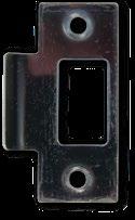

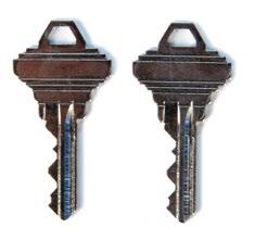


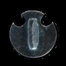

3 What s in the box? Let s make sure you have everything you need. If you re missing anything, contact support@remotelock.com. Strike Plate 2 Adhesive Gaskets 2 Keys Support Post Storeroom Tailpiece (Optional) Aux Function Wires (Optional) 2 Lever Handles Interior Lock Exterior Lock 2⅜ inch (60mm) and 2¾ inch (70mm) latch Spindle Hardware Set
4 You are here. 1 2 Install your lock. Use this Hardware Installation guide to get your lock hardware installed. Get connected. Use the Connection Guide to get your lock online and registered. Let s get started. 3 Take control. Now your lock is fully functional and can be managed from anywhere. First things first, let s get your new lock installed.
 support hole and prepare the door for drilling.")
5 STEP 1 Position the template. This guide assumes the door is already prepped with a 2⅜ inch boring hole. Use the provided drilling template to mark the upper ⅜ inch (10mm) support hole and prepare the door for drilling. Crease the template along the dotted lines matching the backset for your door (2⅜ inch (60mm) or 2¾ inch (70mm) latch). Quick Tip The backset is the distance between the center of the boring hole to the edge of the door.

6 Ensure the folded edge of the template is flush with the door edge and that the center latch line is centered over the latch opening. View the template from the other side of the door to make sure the dotted latch line on the template is exactly centered within the boring hole opening. Once the template is aligned, tape the template in place.

7 STEP 2 Mark carefully. Mark the center of the upper, ⅜ inch (10mm) hole to be drilled using a sharp object, like a nail or a thumbtack. After marking the exterior of the door, apply the template to the interior of the door using the same methods. Make sure the holes are aligned exactly from one side of the door to the other and double check all the measurements and markings to ensure precision. Mark the center of the ⅜ inch (10mm) hole to be drilled from the other side of the door.

8 STEP 3 Drill holes. Exterior of Door Prepare your power drill with a ⅜ inch (10mm) drill bit. Align the drill bit over your mark and hold the door steady. Keep the drill level and straight. Drill halfway through on the first side. Then drill the remaining half from the other side of the door. This prevents blowback damage to the door and improves accuracy. Interior of Door Quick Tip Since the 2⅛ inch (54mm) boring hole already exists in this example, the lower support bolt will go through the boring hole. Only the upper 10mm hole will need to be drilled. If your door is prepped with a smaller boring hole, use the template to drill the additional lower 3/8 inch support.
9 STEP 4 Install latch. Exterior of Door Doors are typically prepped with either a 2⅜ inch (60mm) or 2¾ (70mm) inch backset. Latches are provided for either option. This installation will be pictured with the standard 2⅜ inch (60mm) latch. Insert the latch in the door, making sure the beveled side faces the door jamb. Use the provided screws to secure the latch in place. Exterior of Door Quick Tip Make sure the latch plate lays flush with the door. If the latch plate is not flush in the door, draw an outline around the faceplate edge and chisel a rebate to allow the latch to lay flush with the door edge.

10 STEP 5 Install spindle. Exterior of Door Place the spindle into the latch with the spring on the exterior (keypad side) of the door. The spring ensures that the spindle remains in contact with the front of the lock. Quick Tip Make sure the spindle s spring is on the exterior side of the door. If you install the spindle with the spring on the interior side of the door, the lock will not work properly.


11 STEP 6 Attach the latch support post. Next, attach the latch support post to the lock. This post will be screwed into either the left or right of the center hub. The hole that you will use depends on whether your door is a left-hand or right-hand door and which size latch is used. View your latch from the exterior side of the door to determine which support post position to use, then screw the post into the lock. Quick Tip When using the 2⅜ inch latch, use the inner holes closest to the center hub. If using the 2¾ inch latch, use the outer holes.

12 STEP 7 Attach the gaskets. Fit the self-adhesive gaskets on the backplate of each side of the lock. Peel the white backing off the gasket and apply to the backplate of the lock. Be sure to align the edges and pull the antenna and power cable through the appropriate hole, as shown. Quick Tip Take a picture of the serial number sticker on the back of the lock. The serial number can also be found on the exterior of the lock s packaging.


13 STEP 8 Prepare the interior lock. Remove the screw that secures the battery cover and lift the plastic cover off of the lock. Next, remove the battery pack and set them both aside.

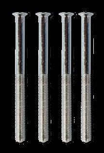
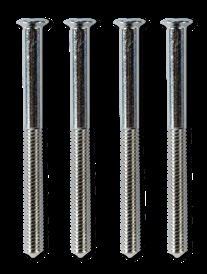
14 STEP 9 Measure door depth. It s vital to use the correct mounting bolts for your door s thickness. Two sets of different sized bolts are provided, as well as a set of bolts with cut points that can be cut to size if needed. Place one of the bolts through the mounting bolt hole on the upper, battery pack side of the lock. Hold the lock flush with the door but allow the bolt to pass along the edge of the door to gauge its length. The correct bolt should go about a ½ inch past the edge of the door. ½ inch

15 Optional Step If neither of the 2 pre-cut bolt lengths work for your door, you will need to cut the fixing bolts to the correct length. Using the same method, align the bolt along the side of the door and choose a cutting point approximately ½ inch beyond the edge of the door. Quick Tip Always cut the bolts at one of the cutting points so as not to damage a thread. Use the cutting edges of pliers to crimp around the selected cutting point. If the cut produces a sharp point, use sandpaper to smooth the tip of the bolt. Cutting Points and Door Depth
 side of the lock has two important cables")


16 STEP 10 Place lock exterior. The exterior (keypad) side of the lock has two important cables sticking out of its backplate; a power cable and a Wi-Fi antenna cable. Pass the antenna and power cable over the latch. Align the support post through the hole in the latch, and make sure the spindle fits snugly in the lock s hub. IMPORTANT Be sure to pass the power cable and antenna over the latch in the door, not under.


17 STEP 11 Place lock interior. Feed the power cable and the antenna through the hole above the main spindle hole. Once the cords are inside the lock, pull them up and out of the battery pack housing.

. Quick Tip Leave the top screw somewhat loose before screwing in the bottom screw.")
18 STEP 12 Secure lock. With the power cable and antenna cable coming through the lock housing, make sure the lock is level and straight. Place the fixing bolts through the interior lock mounting holes and then tighten into the front side of the lock. Both screws are needed: one at the top of the lock (through the drilled hole) and one on the bottom of the lock (below the handle going through the boring hole). Quick Tip Leave the top screw somewhat loose before screwing in the bottom screw. Tighten both screw back and forth until snug. Do not over tighten.

19 STEP 13 Test the lock. Now that the lock is mounted to the door, make sure that the lever and the latch move freely. Turn the inside handle boss to check that the spindle moves freely and the latch retracts and projects smoothly. If the lock was secured too tightly to the door, you may find that the spindle or latch sticks. To correct this, loosen the fixing bolts and adjust the position of both sides of the lock until the spindle moves freely.
 into the battery pack.")

20 STEP 14 Connect battery pack. Insert 4 AA batteries (not included) into the battery pack. Connect the power cable from the lock to the battery pack by connecting the two plugs. You should hear and feel a click when the cables connect.


21 STEP 15 Position power cord. Push the power plug down and to the side of the lock housing, along with the wires. This provides room for the battery pack and the battery cover.


22 STEP 16 Insert battery pack and connect antenna. Now slide the battery pack back into the lock housing with the top wires facing out. Connect the gold Wi-Fi antenna to the battery cover plate by clicking it in place. Quick Tip Plug the antenna into the connector as you would plug in headphones. The connector will plug in, rather than screw in.

23 STEP 17 Attach the battery cover. Slide the battery cover back onto the lock interior and screw it in. Quick Tip Position the batter cover just above the lock and then slide straight down into place.
")

24 STEP 18 Attach exterior handle. Place the key cylinder cover over the key cylinder located on the exterior (keypad side) of the lock. Use the provided Allen key to loosen the small screw on the appropriate handle. The handle should point away from the latch toward the hinges. Slide the handle over the handle boss and tighten the handle screw with the Allen key.


25 STEP 19 Attach interior handle. Use the provided Allen key to loosen the small screw on the other handle. Slide the handle over the handle boss and tighten the handle screw with the Allen key. Turning the interior handle should retract the latch bolt. The exterior handle should turn freely without retracting the latch.
26 STEP 20 Test your lock. Enter the factory default code 1234, followed by the # button to unlock the lock. Congratulations! Your lock is now installed. The keypad will flash green and the outside handle will now retract the latch. Auto lock is enabled and the lock will re-lock after 5 seconds. These settings can be configured in the portal after connecting your lock to Wi-Fi. To lock the lock, press the * button twice. Please note that, for security purposes, the default access code will be deleted after 24 hours or when your first access user is created. If you do not change the code yourself, it will be set to a randomized code for your protection. You can find this new code in the RemoteLock app. Next: Use the Connection Guide to finish setup.
27 Default Settings By default, and after a factory reset, your lock has the following settings: Programming Code: User Code: 1234 Passage Mode: Disabled Auto-Lock Delay: 5 Seconds Keypad Sound: Enabled Heartbeat Interval: 1 Hour Programming Functions You can use the keypad to perform several functions. These functions can also be performed remotely from the RemoteLock app. None of the following functions are required for setup. All keypad programming functions follow the same general steps: 1. Enter your, followed by the # button. 2. Enter the for the desired function, followed by the # button. 3. Some functions will also require you to enter a, followed by the # button.
28 Function Codes 100: Change Programming Code The programming code is essentially a password. This code allows you to program the lock directly, using the keypad. By default, the code is You can change this code to any anything 4-8 digits in length. To set a new programming code, enter the following on the lock s keypad: Enter your current followed by the # button, 100 followed by #, and then enter your followed by #. If successful, you will see two green flashes and hear two beeps. If an error was made, you will see a red flash. 110: Add a Local User Code Local User Codes are intended to be used as a backup to User Codes created from the app. If internet is unavailable, you can program a code directly from the lock. Note that schedules cannot be applied to a Local User Code. Local User Codes can be 4-8 digits in length. To Add a Local User Code, enter the following on the lock s keypad: Enter your followed by the # button, followed by #, and then enter your desired followed by #. Once set, the default User Code will be disabled after your Local User Code is created.
29 Function Codes (cont) 120: Delete Local User Code If you would like to remove your Local User Code, enter the following on the lock s keypad: Enter your followed by the # button, followed by #, and then enter the existing followed by #. 130: Erase ALL Local Codes If you would like to remove ALL of your existing Local Codes, enter the following on the lock s keypad: Additional Functions 131: Erase all user codes, except 1234 default. 135: Perform a factory reset. Careful, this will delete all codes, schedules and events. 160: Mute keypad beeping. 161: Unmute keypad beeping. 270: Disable Passage Mode. Your lock will automatically lock after each use. 271: Enable Passage Mode. Your lock will stay unlocked after being unlocked. 312: Reset Wi-Fi connection. (Forget All Known Connections and Networks). Enter your followed by #. followed by the # button, 320: Enter Access Point Mode to allow connection to another network. 411: Enter 411, * to force Wi-Fi to wake up if the lock is currently set to not wake up on keypress.
30 Changes or modifications not expressly approved by the party responsible for compliance could void the user s authority to operate this equipment. Notes This device complies with Part 15 of the FCC Rules. Operation is subject to following two conditions: (1) This device may not cause harmful interference, and (2) This device must accept any interference received, including interference that may cause undesired operation.
31 Visit us online. support.remotelock.com We re here to help. 1 (877) support@remotelock.com
CL4500 Installation Instructions
 CL4500 Installation Instructions Box Contents Check the contents of the box are correct according to the model 4510 4520 1 Front Plate 2 Back Plate 3 Lever Handles 4 Gaskets 5 Sprung Spindle (x1) 6 Spring
Installing Your Electronic Deadbolt
 Ultra Security Plus Electronic Deadbolt Installation Instructions http://www.hberger.com/video-gallery/electronic-deadbolt New Installation Lock Location Preparation (Skip this section if you door has
Installation Instructions II-2/4/5K-0608
 Installation Instructions II-2/4/5K-0608 Box Contents Check the contents of the box are correct according to the model 2010 4010 4020 5010 5020 1 Front Plate 2/4000 - - 2 Front Plate 5000 - - - 3 Back
Shepherd 210A Fingerprint Door Lock Installation Manual V1.1
 Shepherd 210A Fingerprint Door Lock Installation Manual V1.1 Hongda USA Inc. 2505 Technology Dr. #2-6A, Hayward, CA 94545, USA Phone: (510) 887-5682 Fax: (510) 372-0487 Email: info@hongdausa.com Website:
Tools Required. * When installing on a fire door, please see instructions below. *
 CL615 Tubular Mortice Latch with Code Free option CL615 Tubular Mortice Latch with Code Free option Number relating to picture Item 1 Front Plate and handle * 2 Back Plate and handle * 3 Neoprene seals
Parts. Backplate. Battery Cover. Backup Key. Touchscreen Assembly. Inside Assembly. Thumbturn. Strike. Reinforcement Plate. Bolt.
 Quick Start Guide Backplate Backup Key Battery Cover Touchscreen Assembly Parts Strike Bolt Inside Assembly Thumbturn Reinforcement Plate Set Screw Reinforcement Screws Inside Assembly Screw Backplate
CM5100 COMPUTER MANAGED CYLINDRICAL LOCK HARD-WIRED (FSE/FSA) INSTALLATION MANUAL
 INSTALLATION MANUAL") The 5100 series lock is a stand-alone, microprocessor controlled, electromechanical locking system. The 5100 employs a heavy-duty mechanical design which is easy to install and highly reliable. The FSE
The 5100 series lock is a stand-alone, microprocessor controlled, electromechanical locking system. The 5100 employs a heavy-duty mechanical design which is easy to install and highly reliable. The FSE
INSTALLATION INSTRUCTIONS
 INSTALLATION INSTRUCTIONS ANSI/BHMA - A156.2 BOX CONTENTS CHECK THAT THE CONTENTS OF YOUR BOX ARE CORRECT ACCORDING TO THE MODEL Model 600/605 Model 610/615 Model 620/625 1 Front plate and handle 2 Back
Door Hardware Installation Instructions. For Assistance Call:
 For Assistance Call: Door Hardware Installation Instructions Single Cylinder NOTE: s fit doors 1-3/4 to 2-1/4 thick. For thicker doors, please call customer service. Carefully unpackage all components
CRCODE-202. Mechanical Lock. Instruction and Programming Manual. Before Installing:
 CRCODE-202 Mechanical Lock Instruction and Programming Manual Before Installing: 1. Please read the instructions carefully to prevent missing important steps. *Note: Improper installations may result in
PMR ELECTRONIC LOCK USER GUIDE
 封底 封面 148.5 x 210(mm) www.ezset.com.tw PMR ELECTRONIC LOCK USER GUIDE 封面裡 Parts Introduction Do not use an electric screwdriver when installing the product! Installation Procedures 1. Draw horizontal lines
CM5500 COMPUTER MANAGED MORTISE LOCK HARD-WIRED (FSE/FSA) INSTALLATION MANUAL
 INSTALLATION MANUAL") The 5500 series lock is a stand-alone, microprocessor controlled, electromechanical locking system. The 5500 employs a heavy-duty mechanical design with fewer moving parts that a standard mechanical mortise
The 5500 series lock is a stand-alone, microprocessor controlled, electromechanical locking system. The 5500 employs a heavy-duty mechanical design with fewer moving parts that a standard mechanical mortise
Installation Instructions For Profile Series v.g1 Exit Device
 Installation Instructions For Profile Series v.g1 Exit Device A7757C Copyright 2004, 2008, Sargent Manufacturing Company, an ASSA ABLOY Group company. All rights reserved. Reproduction in whole or in part
120x165mm. 85x165mm TEMPLATE. ELECTRONIC DEADBOLT model no.: & & Toll-free Number:
 20x65mm 85x65mm ELECTRONIC EABOLT FOR BACSET 2 3/4" ( 70 mm) FOR BACSET 2 3/8" ( 60 mm) Ø 2 /8" ( 54 mm ) Toll-free Number: -800-268-659 IMPORTANT: Please read this manual carefully before installing this
Installation Instructions
 999-00451 Smart Deadbolt Secure control from anywhere. Installation Instructions Simply Smart Security. Installation Instructions 999-00451 Box Contents Screw Cover Key (2) Exterior Assembly Gasket Drive-in
SCHLAGE SENSE. Smart Deadbolt. Installation Instructions. Download the Schlage Sense app to get started!
 SCHLAGE SENSE Smart Deadbolt Installation Instructions Download the Schlage Sense app to get started! Schlage Sense Installation Instructions Package Contents Camelot Style shown throughout guide. Support
Entry Mortise Lock Set Lever to Lever
 Entry Mortise Lock Set Lever to Lever 1 Lever 2 Escutcheon 3 Turn Piece 4 Mortise Lock 5 Scalp 6 Mortise Lock Strike 7 Mortise Lock Dust Box 8 Mortise Cylinder 9 Cylinder Swing Cover 10 Spindle 11 Spindle
Entry Mortise Handleset
 1. Pencil 2. No. 2 and No. 3 Phillips Head Screwdrivers 3. No. 1 and No. 2 Slotted Screw Drivers 4. 1/8" Allen Head Wrench 5. 3/4" Wood Chisel or Corner Chisel 6. Measuring Device 7. Lock Mortising Tool
CM5500 COMPUTER MANAGED MORTISE LOCK INSTALLATION MANUAL
 The 5500 series lock is a stand-alone, microprocessor controlled, electromechanical locking system. The 5500 employs a heavy-duty mechanical design with fewer moving parts that a standard mechanical mortise
Passage Mortise Lock Set Lever to Lever
 Passage Mortise Lock Set Lever to Lever 1 Lever 2 Escutcheon 3 Mortise Lock 4 Scalp 5 Mortise Lock Strike 6 Mortise Lock Dust Box 7 Spindle 8 Spindle Spring 9 Spindle Retainer 2 1 9 8 7 9 7 8 3 1 2 4 5
INSTALLATION INSTRUCTIONS FOR INSTALLING T-SERIES EXTRA HEAVY DUTY LEVER LOCKSET
 HIGH EDGE 2 1/4"(57mm) 03079400070 INSTALLATION INSTRUCTIONS FOR INSTALLING T-SERIES EXTRA HEAVY DUTY LEVER LOCKSET IMPORTANT: THIS LOCK IS NON-HANDED. LOCK IS FACTORY PACKED PREADJUSTED FOR 1³ ₄" (45mm)
Installation Guide. Cue Front Unit (Code and Key) Cue Front Unit (RFID) Cue Rear Unit (Latch and Bolt)
 Cue Front Unit (RFID) Cue Rear Unit (Latch and Bolt)") Installation Guide Cue Front Unit (Code and Key) Cue Front Unit (RFID) Cue Rear Unit (Latch and Bolt) Table of Contents Before Lock Installation3 Surface Mount Installation For door thickness measuring
Installation Guide Cue Front Unit (Code and Key) Cue Front Unit (RFID) Cue Rear Unit (Latch and Bolt) Table of Contents Before Lock Installation3 Surface Mount Installation For door thickness measuring
Congratulations! You are now on your way to enriching your life with!
 C) Using the base point as your reference, measure up 8-1/32 and mark a horizontal line. Measure in from the edge of the door the distance of your backset and mark where the two lines cross. This will
SCHLAGE SENSE. Smart Deadbolt. Installation Instructions. Download the Schlage Sense app to get started!
 SCHLAGE SENSE Smart Deadbolt Installation Instructions Download the Schlage Sense app to get started! Schlage Sense Installation Instructions Package Contents Camelot Style shown throughout guide. Support
BL-ER-P Ethernet Radio Unit for Pedestal Installation Guide
 Assemble the Antenna Riser 1. Remove the antenna riser assembly and the antenna from its packaging. 2. Remove the plastic cap, the nut, and the lock washer from the stem of the antenna. 3. Put the stem
Congratulations! You are now on your way to enriching your life with! Figure #5. Step 5 Install the Dummy Deadbolt. Step 3 Drill the Door
 C) Using the base point as your reference, measure up 8-1/32 and mark a horizontal line. Measure in from the edge of the door the distance of your backset and mark where the two lines cross. This will
Stage 2: Preparing the door (read in conjunction with Hole Drilling Options on back of Template).
.") There are three stages to fitting the CL100 mortise case: Stage 1: Marking out the position of the lock. Stage 2: Preparing the door by mortising and drilling holes. Stage 3: Fitting lock, door furniture,
There are three stages to fitting the CL100 mortise case: Stage 1: Marking out the position of the lock. Stage 2: Preparing the door by mortising and drilling holes. Stage 3: Fitting lock, door furniture,
Installation Instructions For Profile Series v.g1 Cylindrical Lock
 Installation Instructions For Profile Series v.g1 Cylindrical Lock A7755A Copyright 2004, 2008, Sargent Manufacturing Company, an ASSA ABLOY Group company. All rights reserved. Reproduction in whole or
Installation And Programming Instructions For Profile Series With RF Technology
 Installation And Programming Instructions For Profile Series With RF Technology A7691A www.sargentlock.com 1 Table of Contents General Description Page 2 3 4 5 6 7 Installation of RF Technology Lock...1
E-PLEX 3X00 SERIES NARROW STILE LOCK INSTALLATION INSTRUCTIONS
 E-PLEX 3X00 SERIES NARROW STILE LOCK INSTALLATION INSTRUCTIONS TABLE OF CONTENTS Tools Required.................................................................3 A. Door Preparation - Remove Existing Outside
VIT SB-16SS Pedestal. Conversion Guide
 Converting a to Baseline This guide describes the steps for removing another manufacturer s irrigation controller from a VIT SB-16SS pedestal and installing a Baseline controller. Remove All Parts of the
LET S GET STARTED INSTALLATION GUIDE
 LET S GET STARTED INSTALLATION GUIDE THANK YOU. We re incredibly excited to bring Lockitron Bolt to your door. If you need any help with set up, please reach out to us at support@lockitron.com. We re happy
EmagiKit. Privacy Pod Plus. Quiet. Easy. Affordable. INSTRUCTIONS ASSEMBLY
 EmagiKit Privacy Pod Plus Quiet. Easy. Affordable. INSTRUCTIONS ASSEMBLY DIMENSIONS AND COMPONENTS 47 47 Ceiling Unit 2-B 2-L 2-R Glass Door Corner Trim Door Handle 90 Adjustable Height Work Surface 1-B
Door Hardware Installation Instructions. Version A No Interior on an Un-prepped Door Step 1 Select the Position of the Handleset
 For Assistance Call: 1-800-522-7336 8 am - 5 pm, Monday - Friday, MST or visit our Website at: www.grandeur-nw.com Door Hardware Installation Instructions Dummy Handleset Optional Rosette (Round) Interior
PLEASE READ THIS NOTICE BEFORE BEGINNING ANY PHASE OF INSTALLATION!!!!
 PLEASE READ THIS NOTICE BEFORE BEGINNING ANY PHASE OF INSTALLATION!!!! This kit is designed to be installed by someone with a fair amount of mechanical aptitude. However, if you are not comfortable making
Installers guide Deadbolt 02.
 Installers guide Deadbolt 02. version 0.7.1 Specifications Model igloohome Smart Deadbolt 02 Material Zinc Alloy Current Rating (Standby) ~30uA Current Rating (Active) ~200mA Batteries 4 x AA Alkaline
INSTRUCTIONS FOR HIT TEMPLATE FOR CYLINDRICAL LOCK PREPS
 1825 VIA BURTON ANAHEIM CA 92806 714-772-5202 / FAX 714-772-2302 EMAIL: MAIL@MAJORMFG.COM WEB: WWW.MAJORMFG.COM INSTRUCTIONS FOR HIT-66-110 TEMPLATE FOR CYLINDRICAL LOCK PREPS WHEN USING POWER TOOLS ALWAYS
ProLogic Xtreme L22 - Electromechanical Redundant Safe Lock System - Instructions
 ProLogic Xtreme L22 - Electromechanical Redundant Safe Lock System - Instructions Please visit the website below by scanning the QR code with your smartphone or by typing in the address below for video
Assembly Instructions Nevins Phone Booth
 Assembly Instructions Nevins Phone Booth Included Hardware Tools Required supplied by installer Drill & Bit Bolt A - (16) 1/4-20 x 1-1/2 hex head Bolt B - (20) 1/4-20 x 2-1/2 phillips head Screw 1 - (24)
For installation assistance, contact SARGENT at DOORS SHOWN HERE SWING IN FOR ILLUSTRATION PURPOSES ONLY.
 SARGENT Installation Instructions for LP8600 x LR8600 & 12-LP8600 x 12-LR8600 Series Low Profile Panic and Fire Exit Devices on Double Egress & Double Doors or LS8600 & 12-LS8600 Low Profile Exit Device
Before Lock Installation Surface Mount Installation. Door Preparation. For door thickness measuring between.01" -.91" (0.2 mm - 23 mm)...
...") Installation Guide Before Lock Installation... 3 Surface Mount Installation For door thickness measuring between.01" -.91" (0.2 mm - 23 mm)... 4 Required Components... 4 Installation... 5 Door Preparation
Installation Guide Before Lock Installation... 3 Surface Mount Installation For door thickness measuring between.01" -.91" (0.2 mm - 23 mm)... 4 Required Components... 4 Installation... 5 Door Preparation
Installation Instructions for Trilock Omni BB Twin Pull Handle Version - Suits 35mm to 45mm door thickness
 Installation Instructions for Trilock Omni BB Twin Pull Handle Version - Suits 35mm to 45mm door thickness Step 1. Fold template where indicated. Position template on door edge at desired lock / latch
CrossOver X25 Lock Installation Need another copy of these installation sheets? You can download one at
 CrossOver X25 Lock Installation Need another copy of these installation sheets? You can download one at www.crossoverlock.com/supportcenter.htm 1 Back view of installation Major lock parts 1. Rear handle
Assembly Instructions Nevins Phone Booth
 Assembly Instructions Nevins Phone Booth Included Hardware Tools Required supplied by installer Drill & Bit Socket Wrench Bolt A - (16) 1/4-20 x 1-1/2 hex head Bolt B - (20) 1/4-20 x 2-1/4 phillips head
HIT-30 ALUMINUM DOOR SERIES OWNERS MANUAL
 HIT-30 ALUMINUM DOOR SERIES OWNERS MANUAL INSTALL LOCKS LATCHES LEVERS / PADDLES INDICATORS STRIKES Every Installation Is A Self-Portrait Of The Person Who Did It! Autograph Your Work With Excellence!
Installation Instructions ENGLISH
 Installation Instructions ENGLISH Interior Latchset PRIVACY (Bed & Bath) PASSAGE (Hall & Closet) PK.5400 Congratulations! With your purchase of this Interior Latchset, you re among a group of discerning
INSTALLATION INSTRUCTIONS REPLACING EXISTING DEADBOLT ASSEMBLY
 INSTALLATION INSTRUCTIONS REPLACING EXISTING DEADBOLT ASSEMBLY A B C L M N D E F G O P Q H I J Tools provided in Amesbury installation kit: (A) door router fixture, (B) doorframe router fixture, (C) ½
Installation Guide. Cue front unit (code and key) Cue rear unit (latch and bolt)
 Cue rear unit (latch and bolt)") Installation Guide Cue front unit (code and key) Cue rear unit (latch and bolt) Before Lock Installation... 3 Surface Mount Installation For door thickness measuring between.01" -.91" (0.2 mm - 23 mm)...
Installation Guide Cue front unit (code and key) Cue rear unit (latch and bolt) Before Lock Installation... 3 Surface Mount Installation For door thickness measuring between.01" -.91" (0.2 mm - 23 mm)...
P USHbutton 500 series
 Dimensions 35 60mm 178mm Model 500/505 For use with existing lock 1 6 2 7 3 8 4 9 5 0 1 6 2 7 3 8 4 9 5 0 Features ode Free Entry Mode by turning the slotted button 90 degrees after entering the code (models
WD WD7000 Series
 WD-7000 12-WD7000 Series Wood Door Concealed Vertical Rod Multi-Point Lock Installation Instructions Copyright 2015, Sargent Manufacturing Company, an ASSA ABLOY Group company. All rights reserved. Reproduction
Safety glasses Measuring tape Level Pencil Power drill Center punch Phillips screw driver Saw horse
 EX76 Concealed Vertical Rod Exit Device Preparation Guide and Installation Instructions Box Contents EX76 Concealed Vertical Rod Exit Device Back Bar Active Push Bar Filler Plate Door Kit with Templates
Before Lock Installation Surface Mount Installation. Door Preparation
 Installation Guide Before Lock Installation... 3 Surface Mount Installation For door thickness measuring between.01" -.91" (0.2 mm - 23 mm)... 4 Required Components... 4 Installation... 5 Door Preparation
Installation Instructions For The 8850FL Series Mortise eboss
 Installation Instructions For The 8850FL Series Mortise eboss Electronic Battery Operated Security Solution FEATURES Battery Operated (Hardwire Capable) Motorized Grade 1 Mortise Lock 94 User Code Capacity
ASSA ABLOY. Installation Instructions. MP9800 Series Multi-Point Lock. MP9800 Series Multi-Point Lock Wood Doors. Wood Doors ASSA ABLOY.
 Installation Instructions MP9800 Series Multi-Point Lock MP9800 Series Multi-Point Lock, the global leader in door opening solutions 1 of 12 Copyright 2016 Corbin Russwin Inc., an Group company. Table
Rim-Lock Door Set Installation Instructions
 Rim-Lock Door Set Installation Instructions Let s get started Check Your Parts List Two Doorknobs with Set Screws B. Doorknob Spindle C. Rim Lock with Mounting Screws D. Keeper with Mounting Screws E.
Installation Instructions
 for s TOC Table of Contents 1 Mortise Lock Handing Instructions.... 2 2 3 4 5 Mortise Lock Door Preparation & Installation... 3 HSS Trim Installation.... 5 Knob x Knob...6 Lever x Knob....7 Turn-Piece
ED1300/1300F SERIES CONCEALED VERTICAL ROD DEVICE INSTALLATION INSTRUCTIONS
 ED1300/1300F SERIES CONCEALED VERTICAL ROD DEVICE INSTALLATION INSTRUCTIONS Ver.2 1300 SERIES CONCEALED VERTICAL ROD DEVICE Top Strike Latch Screws Strike Screws Release Plunger Top Latch Plunger Screws
WARNING: Prior to installation, turn the power off to the vending machine and unplug it from its power source. Also, make sure to level the machine.
 Installation of Gum and Mint Tray for National 147, 157, 167 Important Note: Please read all instructions thoroughly before continuing with installation of kit. If you are having problems installing the
Installation & Programming Guide
 Installation & Programming Guide EMTouch & EMTouch Classic Style Electronic Deadbolt Locksets EMTouch EMTouch Classic Style ASSA ABLOY, the global leader in door opening solutions What s in the Box 4a
Installation instructions for the Apex and Volt Electric Locksets
 Please refer to G+ Lockset Installation Manual for Instructions on how to use this template Paper size A3. These dimensions are for reference only to ensure that scale is correct. Power transfer unit heights
Installation Instructions. Oakmont Folding Doors
 Before You Start For quick and easy installation of your Oakmont folding door, read these instructions thoroughly. A few minutes of prior planning will make the job easier and ensure years of trouble-free
MultiTable Mod-E 2 Electric Standing Desk
 The Height of Healthy Design MultiTable Mod-E 2 Electric Standing Desk ASSEMBLY INSTRUCTIONS MultiTable Mod-E 2 Electric Standing Desk Frame PARTS AND TOOLS PLEASE REVIEW these instructions before beginning
INSTALLATION INSTRUCTIONS
 INSTALLATION INSTRUCTIONS TM X-10 Type 1F HIGH SECURITY ELECTRONIC LOCK Table of Contents Introduction... 1 Basic Tools and Materials Needed... 1 Lock Parts for Installation... 1 Installation Kit Contents...
Travel Trailer Latch With Dead Bolt Trailer Latch With Dead Bolt. U.S. Patent No. 5,927,773
 60-250 Travel Trailer Latch With Dead Bolt 60-251 Trailer Latch With Dead Bolt Service Manual (Installation and Troubleshooting) U.S. Patent No. 5,927,773 CONTENTS 1. BASIC COMPONENTS 2. INSTALLATION OF
Legacy Woodworking Machinery a division of Phantom Engineering. The Legacy CNC. Assembly Manual
 Legacy Woodworking Machinery a division of Phantom Engineering The Legacy CNC Assembly Manual New Orientation of the Legacy Step one: Re-orientation of the machine Remove the X-axis screw and supports.
Installation Instructions
 edium + Heavy duty READ BEFORE INSTALLING UNIT Preliminary instructions: 1. Check window opening size: the mounting parts furnished with this air conditioner are made to install in a wooden sill double-hung
READ BEFORE INSTALLING UNIT INSTALLATION WARNINGS AND CAUTION
 edium + Heavy duty READ BEFORE INSTALLING UNIT INSTALLATION WARNINGS AND CAUTION Carefully read the installation manual before beginning. Pay attention to danger and safety notices. be exposed: Carefully
Phone # La Jolla Doors. Block Frame Installation Manual Aluminum Frame with either Vinyl or Aluminum Panels
 Phone # 800-440-8785 www.lajolladoors.com La Jolla Doors Block Frame Installation Manual Aluminum Frame with either Vinyl or Aluminum Panels Thank you for choosing La Jolla Doors In this manual you will
Harmony Remote Repair
 Harmony Remote Repair harmonyremoterepair.com How to install your new Harmony One Front Cover/Touch Screen Important! Before you begin working on your Harmony One, you must discharge any static electricity
Installation Instructions
 For Medium (15-18.5K) + Heavy duty (22-28.5K) Air Conditioner READ BEFORE INSTALLING UNIT To avoid risk of personal injury, property damage, or product damage due to the weight of this device and sharp
Replacement PVCu Door Lock
 Replacement PVCu Door Lock Universal replacement lock designed to fit most PVCu doors Pack contents Lock Fixing tab Keep Before you begin Please read these instructions carefully Following the steps in
Installation Instructions
 by Precision Screen & Security s 27040 San Bernardino Ave, Redlands, CA 92374 www.precision-screens.com TM Installation Instructions NOTE: Prior to Permanently mounting the BacTrac, insure the handle and
Plexidor Glass Conversion Pet Door Consumer Instructions
 Plexidor Glass Conversion Pet Door Consumer Instructions (Rev 1 2012) Instructions for Installing a Plexidor Pet Door into Glass Sliding Glass Patio Doors French Doors Stationary Windows Other Household
Model 2740B High Security Safe Lock. Installation Instructions. Mounting Considerations:
 Model 2740B High Security Safe Lock Installation Instructions Mounting Considerations: The Sargent & Greenleaf 2740B safe lock is designed to use the same mounting screw locations as common S&G mechanical
Installation Instructions for 45HW & 47HW Electrified Mortise Locks
 Installation Instructions for 45HW & 47HW Electrified Mortise Locks Contents These installation instructions describe how to install your 45HW & 47HW Electrified Mortise Lock. Topics covered include: Finishing
7902 Dado Jig. Owners Manual Please Read Carefully! Hardware List: 7902 Parts List:
 7902 Dado Jig Owners Manual Please Read Carefully! 7902 Dado Jig Hardware List: Identify and verify that you have all of the hardware shown below prior to assembly. Please read the instructions at least
TOOLS REQUIRED Metal Wood Wood and Metal Screws. #16 Drill #12-24 Tap. 1/8 Drill
 DEVICES COVERED IN THIS DOCUMENT: 4700S Surface Vertical Rod Device 4700SF Fire Exit Surface Vertical Rod Device TOOLS REQUIRED Metal Wood Wood and Metal Screws Sex Bolts #7 Drill ¼ -20 Tap #16 Drill #12-24
Pet Door Panel Installation Manual
 Pet Door Panel Installation Manual 400-558-1 1 4/3/03, 3:26 PM Components: Pet Door Panel Panel Latch Assembly Foam Weather-stripping Glass Sweep (4) Binding Posts (6) #6 x 1/2 Sheet Metal Screws (4) 8-32
GETTING STARTED. Instructions IMPORTANT PS B PS B. Record the serial number from the tag on the door front.
 PS-15-20-B IMPORTANT Instructions Record the serial number from the tag on the door front. Keep keys in a secure place away from children. DO NOT STORE KEYS INSIDE SAFE GETTING STARTED When you first receive
PLEASE READ THIS NOTICE BEFORE BEGINNING ANY PHASE OF INSTALLATION!!!!
 PLEASE READ THIS NOTICE BEFORE BEGINNING ANY PHASE OF INSTALLATION!!!! This kit is designed to be installed by someone with a fair amount of mechanical aptitude. However, if you are not comfortable making
WC INSTRUCTION MANUAL 2 PEOPLE REQUIRED SHOWER DOOR KW002
 WC-66-75 INSTRUCTION MANUAL SHOWER DOOR 05.11 2 PEOPLE REQUIRED KW002 IT IS MANDATORY TO HAVE A WALL STUD ON EACH SIDE OF THE SHOWER UNIT TO SECURELY FASTEN THE RAIL TO THE WALLS. GENERAL INSTRUCTIONS
Vigilant Cigar Humidor Vault. Assembly Instructions
 Vigilant Cigar Humidor Vault Assembly Instructions Models: 1000, 1500, and 2000 Congratulations! You have purchased a superior cigar humidor. These humidors have been specifically designed to properly
AUDI A8 D3 REPLACING THE OUTSIDE DRIVER DOOR HANDLE
 AUDI A8 D3 REPLACING THE OUTSIDE DRIVER DOOR HANDLE The keyless entry system in the D3 is a great feature. If you have the car key fob in your pocket, putting your hand under the door handle will unlock
Under Seat Storage Drawer Installation Instructions
 Under Seat Storage Drawer Installation Instructions Parts List: 1) Drawer Assembly 8) Self Tapping Screws 1) Instructions 1) Template Tools Needed: Drill and/or Bit Driver Tape Measure Jigsaw or metal
User Instructions Multiline Otter Scoreboard Caddy Assembly
 List of parts: User Instructions Multiline Otter Scoreboard Caddy Assembly Single Caddy Double Caddy 1 1 Base assembly with attached wheels 2 4 1 1 2 4 4 8 10 20 12 Uprights (60 or 74 aluminum extrusion)
Installation Instructions for 45H & 47H Mortise Locks
 Installation Instructions for 45H & 47H Mortise Locks Contents These installation instructions describe how to install your 45H & 47H Mortise Lock. Topics covered include: Finishing the preparation...
Installation Instructions
 Supafold Slide Aside System Three Fold Room Divider Installation Instructions Distinctive Doors Ltd Supafold Slide Aside Internal Folding System IMPORTANT: Before proceeding with the installation, and
Installation Instruction
 Tools Needed for Assembly Stud finder (for wood stud wall) Pencil Mark Electric drill Wood Stud Wall Installation Step 1. Locate the Wood Studs Installation Instruction Drill bit (for wood stud wall) Masonry
Kwikset, Titan, Ultramax Comparison Eugene Hansen 2004
 Kwikset, Titan, Ultramax Comparison Eugene Hansen 2004 In this article we will compare a Kwikset 400 with a Titan 740 and an Ultramax 740. If the door is already prepared (with 2 1/8 hole either at 2 3/8
This instruction manual is an in-depth look and explanation of how to assemble and install the Murphy Bed properly and efficiently.
 This instruction manual is an in-depth look and explanation of how to assemble and install the Murphy Bed properly and efficiently. Don t be put off by the size of the instruction manual as the large diagrams
Mod-E Pro Electric L-Shaped Standing Desk
 The Height of Healthy Design Mod-E Pro Electric L-Shaped Standing Desk ASSEMBLY AND OPERATION MultiTable Mod-E Pro Electric L-Shaped Table Base PARTS AND TOOLS PLEASE REVIEW these instructions before beginning
Installation Instructions for Deadbolt Models OP 8102LT
 3778 South Kalamath Street, Englewood, CO 80110 Phone (303) 762-7373 Fax (303) 484-4070 www.presomatic.com office@presomatic.com Installation Instructions for Deadbolt Models 8101 8101OP 8102LT Congratulations
Fig. 2 DORMA-Glas Stand/Issue 02/03 Seite/Page 1/7
 FSW Installation instructions Track rail 75 x 72 mm 1. Ceiling substructure and installation of the track rail (Fig. 1): The track rail must be bolted over its entire length (including the stacking track
Your combination is and is not recorded at the factory. This number can be found on the combination slides if required.
 3778 South Kalamath Street, Englewood, CO 80110 Phone (303) 762-7373 Fax (303) 484-4070 www.presomatic.com office@presomatic.com Installation Instructions for Deadlatch Models 8200 8200A Congratulations
Removing and Replacing the Y-truck
 Service Documentation Removing and Replacing the Y-truck To remove and replace the Y-truck you will need the following tools: 4mm Allen wrench 12mm stamped flat wrench #2 Phillips screwdriver (magnetic
STEP BY STEP INSTALLATION INSTRUCTIONS. Studio Hardware. Wall Mount Single Rod Set Motivia Motorized
 STEP BY STEP INSTALLATION INSTRUCTIONS Studio Hardware Wall Mount Single Rod Set Motivia Motorized Everything You Need Table of Contents Step 1 - Getting Started....3 Overview - Wall Mount Single Rod Set
Flat Sheer Shade owner's handbook
 Flat Sheer Shade owner's handbook INSTALLATION INSTRUCTIONS Step 1. Check Package Contents Mounting hardware kit includes the following: Part a.mounting Brackets Quantity 2 for shades up to 45 wide 3 for
VYTEX PREMIUM SLIDING GLASS DOOR. Table of Contents. Precautions and Safety 2. Tools Required...3. Inspect and Prepare Door...4
 VYTEX PREMIUM SLIDING GLASS DOOR Table of Contents Precautions and Safety 2 Tools Required...3 Inspect and Prepare Door...4 Hardware and Parts Check List....4 Master Frame Assembly 5 Master Frame Installation..7
Atrium Patio Door Field Service Manual
 Atrium Patio Door Field Service Manual December 2005 Table of contents Service Agreement Pg 2 Release Agreement Pg 5 Inspection form Pg 6 Warranty Pg 8 Replacing swing panel Pg 12 Replacing sliding panel
1 Removing The Screen Track, Screen and Screen Rollers Note: The screen remains in the track while the track is removed and/or installed.
 Sliding Door Screen and Screen Track Replacement Service Instruction These instructions apply to: Architect Series 12/2004-Current Designer Series 3/2005-Current Tools Required: #2 Phillips head screwdriver