HOLLFELDER CUTTING TOOLS. Main Catalog H6
|
|
|
- Archibald Hamilton
- 5 years ago
- Views:
Transcription
1 HOLLFELDER CUTTING TOOLS Main Catalog H6
 we design and manufacture precision tooling for highest quality demands on most modern CNC-turning / milling / grinding and EDM machines.")

2 HOLLFELDER-GÜHRING CUTTING TOOLS Your competent partner in the area of metal chip removal. At our two company locations in Nuremberg und Zorbau (Germany) we design and manufacture precision tooling for highest quality demands on most modern CNC-turning / milling / grinding and EDM machines. All activities in our enterprise are based on our corporate quality and environmental policy and aim to contribute to a permanent increase in our customers productivity while observing all applicable legal and governmental regulations. Additionally we strive to achieve a leading position in our sector with our products and services and to continuously improve this position by means of a high level of quality as well as an adequate environmental policy. All processes in our enterprise are mainly based on our customers demands and are always supervised by the management team and adapted to the changing general conditions by continuous improvement processes (CIP). In order to achieve our targets we maintain a certificated quality and environmental system according to DIN EN ISO 9001 : 2008 and DIN EN ISO : The perfect composition of highly qualified staff and most modern production methods constitutes the basis for fully developed products on a high quality standard. The easy handling and the adjustability of our milling cutters are the basis for savings in the area of tool presetting as well as for achieving tight tolerances. Our standard program constitutes the basis for a huge number of innovative special tooling solutions which get used and appreciated at our customers globally. In many cases it is the customers specific solution which opens up the full potential of our tooling systems and thus contributes to savings and an increase in productivity. We would be pleased to assist you in selecting the right tooling solution for your specific application and to stay on your side as your competent partner from the start of process planning until the effective use of our tools. Call us, we will also meet your requirement... precise... flexible... innovative. We always appreciate your confidence in us. HOLLFELDER CUTTING TOOLS Headquarters Nuremberg Location Zorbau
3 Contents HPC face mills Milling tools Fineboring tools Ø 6-44 mm Fineboring tools GA 200-Vario Ø mm Drill and chamfering tools Turning tools Ordering numbers for spare parts and accessories Form for customized solutions 3


4 HOLLFELDER CUTTING TOOLS HPC milling cutters 4 precise flexible innovative
5 L Features and advantages page 6-7 Standard range with maximum number of teeth page 8 for maximum feed rates HPC milling cutters page for rough machining Standard range with a reduced number of teeth page 9 for lower spindle power Inserts and spare parts page 10 suitable for a fine and a defined surface finish Inserts and spare parts page 14 for rough milling cutters Adjustment instructions HPC milling cutters page 11 Adjustment instructions HPC rough milling cutters page 15 v c Cutting data recommendations page 16 Application examples page Customer solutions page MQL machining page Form Request for special tooling page 149 5


")

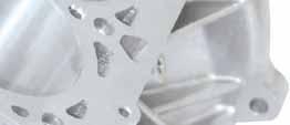
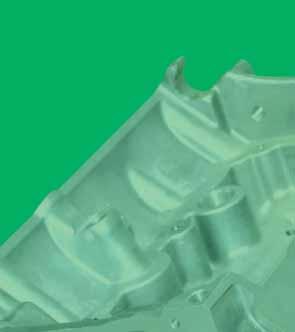
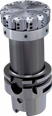
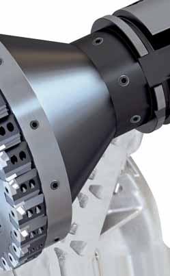
6 HPC milling cutters for rough and finish machining features and advantages Features: Extremely high number of cutting edges for finish machining at milling cutters (i.e. dia. 63, Z=12, dia. 125, Z=27) Easy to set precision adjustable cutting edges Replaceable PCD inserts and carbide chip guiding elements Wear-resistant steelbody, modular design PCD cutting inserts for finish milling are regrindable up to 10 times Enclosed chip flute design Regeneration service for PCD cutting inserts for rough machining Suitable for MQL machining Advantages: Virtually chip-free components, lower cleaning costs Reduced tooling costs per component Extremely high feed rates (up to 60,000 mm/min) Lower machine investment for new projects Tool life improvement by factor 2 to 5 High productivity and energy efficiency HPC-Fräser - Die Spitze der Evolution! Fast, clean, efficient - HPC milling cutter from Hollfelder-Gühring! The super-fast end mills, an evolutionary leap in PCD milling technology 6


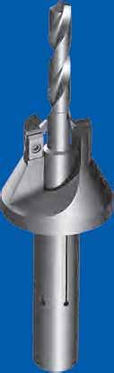
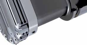
7 HPC milling cutters for rough and finish machining features and advantages Integrated coolant exit Carbide chip guide element Clamping of the inserts Integrated coolant exit Adjustable PCD inserts Secure chip evacuation HPC Face mill Q9934 HPC Face mill Q9936 MILLING CUTTERS FOR ROUGH MACHINING UP TO 8 MM CUTTING DEPTH MILLING CUTTERS FOR FINISH MACHINING UP TO 2 MM CUTTING DEPTH 7
8 HPC milling cutters Standard range with maximum number of cutting edges for cutting depths up to max. 2 mm Ø D L HSK 100-A / HSK 63-A BY HOLLFELDER GÜHRING on request BY HOLLFELDER GÜHRING Code Drawing nr. Diameter/mm teeth L/mm max. rev./min Shank Weight (kg) for maximum feed rates 50,101 Q R ,000 HSK 63-A ,101 Q R ,000 HSK 63-A ,101 Q R ,000 HSK 63-A ,101 Q R ,000 HSK 63-A ,101 Q R ,000 HSK 63-A ,101 Q R ,000 HSK 63-A Code Drawing nr, Diameter/mm teeth L/mm max, rev,/min Shank Weight (kg) for maximum feed rates 50,103 Q R ,000 HSK 100-A ,103 Q R ,000 HSK 100-A ,103 Q R ,000 HSK 100-A ,103 Q R ,000 HSK 100-A ,103 Q R ,000 HSK 100-A ,103 Q R ,000 HSK 100-A 10 Ordering example: 1 piece Q R = Ordering number: ,103 Adjustment instruction page 11 Form Request for customer specific tools page 149 PCD inserts page 10 L 8
9 HPC milling cutters Standard range with a reduced number of cutting edges for cutting depths up to max. 2 mm Ø D L HSK 100-A / HSK 63-A BY HOLLFELDER GÜHRING on request BY HOLLFELDER GÜHRING Code Drawing nr. Diameter/mm teeth L/mm max. rev./min Shank Weight (kg) for lower spindle power 63,106 Q R ,000 HSK 63-A ,106 Q R ,000 HSK 63-A ,106 Q R ,000 HSK 63-A ,106 Q R ,000 HSK 63-A ,106 Q R ,000 HSK 63-A Code Drawing nr. Diameter/mm teeth L/mm max. rev./min Shank Weight (kg) for lower spindle power 63,108 Q R ,000 HSK 100-A ,108 Q R ,000 HSK 100-A ,108 Q R ,000 HSK 100-A ,108 Q R ,000 HSK 100-A ,108 Q R ,000 HSK 100-A 10 Ordering example: 1 piece Q R = Ordering number: ,108 Adjustment instruction page 11 Form Request for customer specific tools page 149 PCD inserts page 10 L 9
10 PCD Inserts and spare parts for finish milling cutters L PCD inserts for HPC finishing cutters Code Drawing nr. Rz Cutting edge length, mm Tool material Tool material suitable for a fine surface finish 99,300 W R PCD 10 PCD 30 suitable for burr free milling 99,340 W R PCD 10 PCD 30 suitable for a defined surface finish 99,320 W R PCD 10 PCD 30 wiper insert (to be used in combination with code no. 99,200 or 99,320) 99,330 W R 5 PCD 10 PCD 30 Chip guiding elements (including clamp screw), CGE set Code Drawing nr. Milling cutter diameter/mm 50,101 E ,99 63,101 E ,99 80,101 E ,99 100,101 E ,99 125,101 E Spare parts Clamping screw Adjustment screw Code Code , ,000 10

11 Adjustment instructions HPC milling cutters The chip guiding elements are mounted ex works! 1. Determine the highest chip guiding element. Recommendation: Place milling cutter in a setting fixture and rotate under the dial test indicator and measure the individual guiding elements. 2. Assemble the milling cutter and tighten the clamping screws (CS 1) to 15 Ncm. Do not tighten the clamping screws (CS 2)! 3. Adjust the inserts in longitudinal direction with the adjustment screws (AS) to 10 μm before the setting dimension. SLE-set CS 1 CS 2 AS Setting dimension = chip guiding element height +30 μm The maximum axial run-out error should be 2 μm. SW 4. Tighten the clamping screws (CS 2) to 80 Ncm, loosen again and tighten to 15 Ncm. 5. Tighten the clamping screws (CS 1) to 80 Ncm. 6. Adjust all the inserts to the setting dimension. The maximum axial run-out error should be 2 μm. Tighten the clamping screws (CS 2) to 80 Ncm. 7. A check measurement is to be carried out after 10 minutes. If the axial run-out error is in excess of 2 μm, the inserts must be re-adjusted without loosening the clamping screws. Torque Torx size Code (Ncm) Torque wrench fixed 15 Tx ,150 Torque wrench fixed 80 Tx ,800 Bit 6 for clamping screws CS1 / CS2 80 Tx ,000 Bit 8 for clamping element 80 Tx ,000 Bit 6 interchangeable blade 15 Tx ,000 Torque wrench adjustable Tx ,810 Spare parts Tool type Code Clamping screw CS1&CS ,000 Q99 Adjusting screw AS ,000 Safety note: In the event of damage the tool must be returned to the manufacturer for checking for technical safety reasons! Only original replacement parts must be used! 11
12 HPC milling cutters for rough machining HSK 63-A L Ø D Ø D 2 Ø D BY HOLLFELDER GÜHRING on request Code Drawing nr. Ø D/mm Ø D 2 /mm teeth L/mm max. rev./min Shank 63,000 Q R ,000 HSK 63-A 80,000 Q R ,000 HSK 63-A 100,000 Q R ,000 HSK 63-A 125,000 Q R ,000 HSK 63-A 160,000 Q R ,000 HSK 63-A 1 BY HOLLFELDER GÜHRING 2 Ordering example: 1 piece Q R = Ordering number: ,000 Adjustment instruction page 15 Form Request for customer specific tools page 149 PCD inserts page 14 L 12
13 HPC milling cutters for rough machining HSK 100-A L Ø D Ø D 2 Ø D BY HOLLFELDER GÜHRING 2 BY HOLLFELDER GÜHRING on request Code Drawing nr. Ø D/mm Ø D 2 /mm teeth L/mm max. rev./min Shank 1 63,001 Q R ,000 HSK 100-A 80,001 Q R ,000 HSK 100-A 100,001 Q R ,000 HSK 100-A 125,001 Q R ,000 HSK 100-A 160,001 Q R ,000 HSK 100-A Ordering example: 1 piece Q R = Ordering number: ,001 Adjustment instruction page 15 Form Request for customer specific tools page 149 PCD inserts page 14 L 13
14 PCD Inserts and spare parts for rough milling cutters L PCD inserts for HPC rough milling cutters Code Drawing nr. R F Cutting length L Tool material 99,340 W R / PCD 30 99,341 W R 0, PCD 30 Chip guiding element (including clamp screw), CGE set Code Milling cutter diameter/mm 63,000 E Spare parts Clamping screw Adjustment screw Code Code , ,000 14

15 Adjustment instructions HPC rough milling cutters The chip guiding elements are mounted ex works! 1. Determine the highest chip guiding element. Recommendation: Place milling cutter in a setting fixture and rotate under the dial test indicator and measure the individual guiding elements. SLE-set 2. Assemble the milling cutter and tighten the clamping screws (CS 1) to 15 Ncm. Do not tighten the clamping screws (CS 2)! CS 1 CS 2 AS 3. Adjust the inserts in longitudinal direction with the adjustment screws (AS) to 10 μm before the setting dimension. SW Setting dimension = chip guiding element height +0.1 mm The maximum axial run-out error should be 2 μm. 4. Tighten the clamping screws (CS 2) to 120 Ncm, loosen again and tighten to 15 Ncm. 5. Tighten the clamping screws (CS 1) to 120 Ncm. 6. Adjust all the inserts to the setting dimension. The maximum axial run-out error should be 2 μm. Tighten the clamping screws (CS 2) to 120 Ncm. Torque Torx size Code (Ncm) Torque wrench fixed 15 Tx ,151 Torque wrench fixed 120 Tx 7/ ,120 Bit 7 for clamping screws CS1 / CS2 120 Tx ,001 Bit 15 for chip guiding element 120 Tx ,000 Bit 7 interchangeable blade 15 Tx ,000 Spare parts Tool type Code Clamping screw CS1&CS ,500 Q99 Adjusting screw AS ,000 Safety note: In the event of damage the tool must be returned to the manufacturer for checking for technical safety reasons! Only original replacement parts must be used! 15


16 HPC milling cutters Cutting data recommendations, Application examples The cutting data recommendations in the table are only guide values and depend to a high degree on the stability of the machine, fixture and workpiece. Cutting groups Material group Composition / structure Tensile strength Hardness RM (MPa) HB HRC Cutting speed vc m/min PCD 10 / PCD 30 Feed rate fz mm/z W W W Aluminium not heat treatable PCD forging alloys heat treatable/heat treated PCD <12% Si not heat treatable PCD Aluminium casting alloys <12% Si heat treatable/heat treated PCD >12% Si not heat treatable PCD 30 HPC milling cutters for rough machining Workpiece Material Tools Cutting speed Revolution Feed per tooth Feed rate Cutting depth Engine block end face G-AlSi11 HPC milling cutter, D = 80 mm, Z = 9, HSK 100-A vc = 3,770 m/min n = 15,000 rev. v./min 0.22 mm 29,700 mm/min 6 mm Achieved surface finish quality Rz =


17 HPC milling cutters Application examples HPC milling cutters for finish machining Sealing surface milling Workpiece Material Tools Gearbox - sealing surface GD-AlSi9Cu3 HPC milling cutter, dia. = 63 mm, no. of cutting edges = 12, HSK 63-A Cutting speed vc = 2,970 m/min Revolution n = 15,000 rev/min Feed per tooth 0.05 mm Feed rate 9,000 mm/min Achieved surface finish quality Rz = 5, Pt = 7, flatness =


18 HPC milling cutters Application examples HPC milling cutters for finish machining Sealing surface milling with defined roughness Workpiece Material Tools Cutting speed Revolution Feed per tooth Feed rate Oil sump GD-AlSi8... HPC milling cutter, dia. = 63 mm, no. of cutting edges = 12, HSK 63-A vc = 1,819 m/min n = 9,500 rev/min 0.16 mm Achieved surface finish quality Rz = 15 18,240 mm/min 18


19 HPC milling cutters Application examples HPC milling cutters for finish machining Workpiece Material Tools Cutting speed Revolution Feed per tooth Feed rate Cylinder head fire face G-AlSi9 HPC milling cutter, D = 125 mm, Z = 27, HSK 63-A vc = 5,890 m/min n = 15,000 U/min 0.15 mm 60,000 mm/min Achieved surface finish quality Rz =


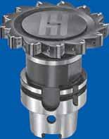
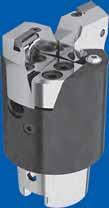
20 HPC milling cutter Special tooling for customer applications Example 1: HPC gang milling cutter, monolithic steel design Diameter 380 mm, z = 2x33 Application: Valve plate mill on a special machine Example 2: Bar cutter for limited space in the tool magazine Diameter 226 mm, no. of cutting edges = 2x2, HSK 63-A Application: Face milling of a valve plate on a MC, complete coverage required 20


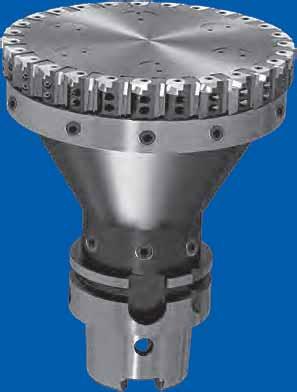
21 HPC milling cutters Special tooling for customer applications Example 3: Version with aluminum intermediate plate (weight reduction!) Diameter 315 mm, no. of cutting edges = 21, HSK 80-C Weight: 18 kg Application: Face milling of a valve plate on a special purpose machine Example 4: Version with cartridges, axially and radially adjustable Diameter 400 mm, no. of cutting edges = 42, HSK 100-C Weight: 37 kg Application: Housing machining on a special purpose machine 21


22 HPC milling cutter for MQL machining MQL machining - Technique and advantages Cost reduction through reduced cleaning effort Environmental and health protection Less cooling lubricant requirements - High cooling and lubricating effect No influence on the process temperature during milling by removing chips Hollfelder-Gühring HPC milling cutters are in principle suitable for MQL machining Catalog standard Customized solutions MQL distributor 1 HRING BY HOLLFELDER GÜHRING BY HOLLFELDER GÜHRING 2 22


23 HPC milling cutter for MQL machining MQL distributor Advantages MQL distributor: absolutely uniform distribution of the oil / air mixture smooth transport by special plastic hoses therefore significantly faster response time protected by patents! Example MQL: Workpiece Cylinder head fire face Material G-AlSi9 Tools HPC milling cutter, dia. = 125 mm, cutting edges = 27, HSK 63-A Cutting speed vc = 4,710 m/min Revolution n = 12,000 rev/min Feed per tooth 0.11 mm Feed rate 35,640 mm/min Achieved surface finish quality Rz =
24 HOLLFELDER CUTTING TOOLS Milling cutters Face milling cutters, Disc milling cutters axially μm-accurate adjustable 24 precise flexible innovative
25 Milling cutters Features page End milling cutters page 28 Face milling cutters as shell milling cutter page 29 Milling arbors page Face milling cutters as monoblock milling cutter page Disc milling cutters page Inserts Features page Insert program from page 42 Regeneration service page 46 v c Application recommendations page Adjustment instructions and security advice page 54 Spare parts page 55 Profitability calculation page 56 Application examples page 57 Form Request for special tooling page
26 Milling cutters axial μm-accurate adjustable with eccentric adjustment innovative HOLLFELDER-GÜHRING CUTTING TOOLS offers the possibility to adjust all inserts of the milling cutter to an exact measure or rather the exact position of the inserts to each other by means of the eccentric adjustment. This system can be applied on the most different materials and impresses with good handling and reliable tension of the cutting edges. The features: Highly exact insert pocket to hold the insert, max. runout 0,03 mm Precision ground insert applicable in right hand as well as in left hand tools Eccentric bolt for μm-accurate axial adjustment Extremely high number of inserts Large clamping element Advantages in the use of these tools: High feed rates due to a high number of inserts lead to an essential increase in productivity Very good face and radial run out accuracies lead to extremely high tool life and excellent surface qualities When completely assembled with insert, the adjustment can easily be made by means of the eccentric bolt which reduce non-productive times The lateral stability is guaranteed by the eccentric bolt as well as the stable clamping element, thus a trilateral machining is possible 26


27 Milling cutters axial μm-accurate adjustable with eccentric adjustment The eccentric adjustment Highly exact insert pocket Adjustment range of the insert Robust clamping element Insert Eccentric bolt Adjustment movement Adjustment instruction page 54 27
 adjustable b 90 L1 L uneven tooth-pitch balanced G 6,3 at 15.000 1/min 20000 Code Drawing nr. Ø D teeth b Ø d L 1 L a e2 max.")
28 End milling cutters axial μm-accurate adjustable Central coolant supply directly to all inserts D 0,03 Shank according to DIN 1835 A d h 6 a e 2 ( H ) adjustable b 90 L1 L uneven tooth-pitch balanced G 6,3 at /min Code Drawing nr. Ø D teeth b Ø d L 1 L a e2 max. RPM Weight (kg) Inserts Light and medium machining 32,000 H R /7* W 612 N/R/L 40,000 H R /7* ,000 H R W 3108 N 20,000 H R ,000 H R ,001 H R * PCD-inserts with cutting length of 7 mm see page 44 On request: all tools are also available as left-hand cutting version! ex stock Ordering example: 1 piece H R = Ordering number: ,000 Spare parts page 55 Form Request for customer specific tools page 148 Geometry and grade selection pages vc 28
 Inserts Light and medium machining 40,000 H 6120-4000 4016 R 40 5 12 / 7* 16 24 40 4.5 48.000 0.")

29 d H6 0,03 D Face milling cutters axial μm-accurate adjustable as shell milling cutter 90 b L1 a e 2 Shank according to ISO 6462 adjustable L (adjustable ±0,5) uneven tooth-pitch balanced G 6,3 at /min Code Drawing nr. Ø D teeth b Ø d L 1 L a e2 max. RPM Weight (kg) Inserts Light and medium machining 40,000 H R / 7* W 612 N/R/L 50,000 H R / 7* ,000 H R / 7* ,000 H R / 7* ,000 H R / 7* ,000 H R / 7* Reduced number of teeth 40,001 H R / 7* ,001 H R / 7* ,001 H R / 7* ,001 H R / 7* ,001 H R / 7* ,001 H R / 7* Max. numbers of teeth for light machining 40,002 H R W 3108 N 50,002 H R ,002 H R ,002 H R ,002 H R ,002 H R ,000 H R * PCD-inserts with cutting length of 7mm see page 44 * Central clamping screw for shell milling cutter has to be ordered separately if needed! (see page 55) ex stock Ordering example: 1 piece H R = Ordering number: ,000 v c Application recommendations pages Adjustment instruction page 54 Central clamping screw* for clamping and coolant distribution FKS see page 55 29

30 ISO taper milling arbors Product information Scope of delivery to hold face milling cutters incl. milling retainer screw balancing quality: G6.3 / 15,000 rev./min part no and driving keys ISO taper to DIN ISO form AD/AF internal cooling centrally through the mandrel and over the collar; therefore process and tool life improvement coolant supply form AD/AF bore-ø 40 mm has four additional holes with internal thread for milling heads with tool attachment DIN 2079 and increased tight fitting diameter d2 SK d2 d1 l2 l Code SK arbor-ø d1 d2 l1 l2 kg Availability mm mm mm mm 16, , , , , , , , , Note: To mount the Hollfelder milling cutters, the corresponding central coolant supply FKS to be used! (see page 55) The balancing accuracy has to be tested in the assembled state! 30

31 d2 d1 d3 b HSK-A shell milling arbors Product information to hold shell mills DIN 841, arbor-type single angle cutters DIN 842 with keyway, shell mills DIN 1880 with keyway an milling cutters with inserts DIN 1830 bore-ø 40 and 50 mm has four additional holes with internal thread for milling heads with tool attachment DIN 2079 HSK-A to ISO /DIN internal cooling centrally through the mandrel Scope of delivery completely assembled with milling cutter retaining screw, Part no. 4908, drive dogs, Part no and feather key Part no l2 l Code HSK-A d3 arbor-ø d1 d2 l1 l2 kg Availability mm mm mm mm 16, , , , , , , , , , , , , , , , , , , , , , Note: To mount the Hollfelder milling cutters, the corresponding central coolant supply FKS to be used! (see page 55) The balancing accuracy has to be tested in the assembled state! Positioning of accessories Feather keys DIN 6885 A Scope of delivery minimum order quantity Code for arbor-ø l1 b Availability mm mm mm 4, , , , , , l 1
32 Milling arbors CAT Product information to hold face milling cutters balancing quality: G6.3 / 15,000 rev./min CAT to ASME B5.50 internal cooling centrally through the mandrel and over the collar coolant supply form AD/AF bore-ø 40 mm has four additional holes with internal thread for milling heads with tool attachment DIN 2079 and increased tight fitting diameter D2 Scope of delivery incl. cylindrical screw DIN EN ISO 4762 part no incl. milling retainer screw part no and driving keys CAT d2 d1 l2 l Code CAT arbor-ø d1 h6 d2 l1 l2 kg Availability mm mm mm mm 16, , , , , , , , , , Note: To mount the Hollfelder milling cutters, the corresponding central coolant supply FKS to be used! (see page 55) The balancing accuracy has to be tested in the assembled state! ex stock Spare parts page 55 Form Request for customer specific tools page 148 Geometry and grade selection pages v c 32

33 MAS/BT milling arbors Product information to hold face milling cutters balancing quality: G6.3 / 15,000 rev./min MAS/BT to DIN ISO form JD/JF internal cooling centrally through the mandrel and over the collar; therefore process and tool life improvement coolant supply form JD/JF (* BT30 version JD without coolant supply over collar) clamping-ø 40 with 4 additional tapped holes to hold milling heads with tool attachment DIN 2079 and larger contact-ø d2 Scope of delivery incl. milling retainer screw part no and driving keys BT-50 on request BT d2 d1 l2 l Code BT arbor-ø d1 d2 l1 l2 kg Availability mm mm mm mm 16,030 30* ,030 30* ,030 30* ,030 30* , , , , , Note: To mount the Hollfelder milling cutters, the corresponding central coolant supply FKS to be used! (see page 55) The balancing accuracy has to be tested in the assembled state! ex stock v c Application recommendations pages Adjustment instruction page 54 Central coolant supply FKS Coolant distribution screw for monobloc milling cutters already included 33
 Inserts Light and medium machining 32,000 H 6120-3200 6032 R 32 32 4 12/7* 40 60 4 50.000 0.20 W 612 N/R/L 40,000 H 6120-4000 6032 R 32 40 5 12/7* 40 60 5.4 48.000 0.30 50,000 H 6120-5000 6032 R 32 50 7 12/7* 40 60 9 45.")
34 Face milling cutters axial μm-accurate adjustable as monoblock milling cutter D 0, adjustable 90 b Code Drawing nr. HSK Ø D teeth b L 1 L a e2 max. RPM Weight (kg) Inserts Light and medium machining 32,000 H R /7* W 612 N/R/L 40,000 H R /7* ,000 H R /7* a e 2 L1 L HSK ISO Form A 32,001 H R /7* ,001 H R /7* ,001 H R /7* ,002 H R /7* ,002 H R /7* ,002 H R /7* ,000 H R /7* ,000 H R /7* ,000 H R /7* ,000 H R /7* ,003 H R /7* ,003 H R /7* ,001 H R /7* ,001 H R /7* ,001 H R /7* ,001 H R /7* * PCD-inserts with cutting length of 7 mm see page 44 On request all tools are also available as left-hand cutting version! ex stock Ordering example: 1 piece H R = Ordering number: ,000 Spare parts page 55 Form Request for customer specific tools page 148 Geometry and grade selection pages v c 34
 Inserts Light and medium machining 40,004 H 6120-4000 1210 R 100 40 5 12 / 7* 57 120 5.4 48.000 2.90 W 612 N/R/L 50,004 H 6120-5000 1210 R 100 50 7 12 / 7* 49 120 9 45.000 3.")
35 Face milling cutters axial μm-accurate adjustable as monoblock milling cutter uneven tooth-pitch balanced G 6,3 at /min Code Drawing nr. HSK Ø D teeth b L 1 L a e2 max. RPM Weight (kg) Inserts Light and medium machining 40,004 H R / 7* W 612 N/R/L 50,004 H R / 7* ,002 H R / 7* ,002 H R / 7* ,002 H R / 7* ,002 H R / 7* ,000 H R / 7* Reduced number of teeth 80,003 H R / 7* ,003 H R / 7* ,003 H R / 7* ,004 H R / 7* ,004 H R / 7* ,004 H R / 7* ,005 H R / 7* ,005 H R / 7* ,005 H R / 7* ,001 H R / 7* * PCD-inserts with cutting length of 7 mm see page 44 On request all tools are also available as left-hand cutting version! ex stock Ordering example: 1 piece H R = Ordering number: ,004 v c Application recommendations pages Adjustment instruction page 54 Central coolant supply FKS Coolant distribution screw for monobloc milling cutters already included 35


36 Side milling cutters axial μm-accurate adjustable 3 sided The side milling cutters constitute a further supplementation of our new milling cutter line and are a reasonable completion of our program. As usual all inserts are adjustable, which makes a μm-accurate adjustment of the different tools possible, e.g. in gang milling cutters. For adjustment instructions see page 54. Depending on the customer specific requirement standard inserts can often be used in these milling cutters which is generally possible due to the neutral shape. Special types of the inserts can be delivered within short time. The features: Range Number of teeth Width Special type Ø mm from 8 mm from 5 mm In gang milling cutters standard-inserts are applicable trilateral Total length adjustable (L) Width adjustable (ap) Position of the inserts adjustable (X) a p X L (adjustable ± 0,2) a p X L (adjustable ± 0,2) In groove milling cutters Standard-inserts N-type right-hand and left-hand application possible Width μm-accurate adjustable adjustment range (a p ) depending on the size of insert up to ± 0,2 a p Adjustment instruction page 54 36
37 Side milling cutters axial μm-accurate adjustable Type 3108 and 6120 Ø D 80 - Ø D 100 b 4 D d 4 d 3 uneven tooth-pitch b b a p adjustable Code Drawing nr. Ø D teeth z eff a p b a emax d 3 d 4 b 4 Inserts a e max 80,000 H N W N 80,001 H N ,002 H N ,003 H N ,004 H N / 7* W 612 N/R/L 80,005 H N / 7* ,006 H N / 7* ,007 H N / 7* ,008 H N / 7* ,000 H N W N 100,001 H N ,002 H N ,003 H N ,004 H N / 7* W 612 N/R/L 100,005 H N / 7* ,006 H N / 7* ,007 H N / 7* ,008 H N / 7* * PCD-inserts with cutting length of 7 mm see page 44 Special measurements e.g. from 5 mm onward can be delivered on request in short time available Ordering example: 1 piece H N = Ordering number: ,000 Spare parts page 55 Form Request for customer specific tools page 148 Geometry and grade selection pages v c 37
38 Side milling cutters axial μm-accurate adjustable Type 3108 and 6120 Ø D Ø D 160 b 4 d 4 b b a p adjustable Code Drawing nr. Ø D teeth z eff a p b a emax d 3 d 4 b 4 Inserts 125,000 H N W N 125,001 H N ,002 H N ,003 H N ,004 H N / 7* W 612 N/R/L 125,005 H N / 7* ,006 H N / 7* ,007 H N / 7* ,008 H N / 7* ,000 H N W N 160,001 H N ,002 H N ,003 H N * PCD-inserts with cutting length of 7 mm see page 44 Special measurements e.g. from 5 mm onward can be delivered on request in short time available Ordering example: 1 piece H N = Ordering number: ,000 Spare parts page 55 Form Request for customer specific tools page 148 Geometry and grade selection pages v c 38

39 Side milling cutters axial μm-accurate adjustable Type 3108 and 6120 Ø D Ø D 200 D d 3 uneven tooth-pitch a e max Code Drawing nr. Ø D teeth z eff a p b a emax d 3 d 4 b 4 Inserts 160,004 H N / 7* W 612 N/R/L 160,005 H N / 7* ,006 H N / 7* ,007 H N / 7* ,008 H N / 7* ,000 H N W N 200,001 H N ,002 H N ,003 H N ,004 H N / 7* W 612 N/R/L 200,005 H N / 7* ,006 H N / 7* ,007 H N / 7* ,008 H N / 7* * PCD-inserts with cutting length of 7 mm see page 44 Special measurements e.g. from 5 mm onward can be delivered on request in short time available Ordering example: 1 piece H N = Ordering number: ,004 v c Application recommendations pages Adjustment instruction page 54 39

40 Inserts precision ground the high efficient core parts of our tools are the inserts. The applied cutting materials and coatings fulfil the latest requirements from the market and ensure a cutting performance and tool life on the highest level. The excellent surface finish on the workpiece is a result of the smooth cut of our tools. We create the optimal conditions for this by means of a combination of the insert pocket produced with the utmost precision, the robust clamping element and the precision-ground inserts. Our standard inserts are suited for a variety of fields of application. A help for selecting the right combination of cutting grade, coating and cutting edge geometry for your specific application you will find in the table on page 47. Further you can find cutting data recommendations in the table on page 49. Our application recommendations from page 47 will give you additional information for the efficient use of our tools. The good availability from stock of our standard inserts supports you in saving costs and reduces your capital investment. Especially wiper geometries lead to a better surface finish, higher feed rates along with constant high precisionand reduced machining times. In addition to our standard program we are also prepared to offer other cutting materials and insert geometries on request. 40
 Radius or chamfer Radius or chamfer The neutral type can be used in undercut applications as well as in side milling cutters.")
41 Inserts precision ground Specific features: An essential advantage of the milling cutters inserts is the peripherie-ground geometry for the types W / W N (N = neutral type, trilateral cutting) Radius or chamfer Radius or chamfer The neutral type can be used in undercut applications as well as in side milling cutters. It is also possible in serial production to use one cutting edge in a right-hand cutter and the second cutting edge in a left-hand cutter. Inserts ( W / W N) in neutral type enable Face milling Groove milling Face milling in undercut or the application of the same inserts in side milling cutters Our standard inserts are available ex stock with: Different corner radii Corner chamfers Wiper geometries Edge preparations Cutting grades 41
42 Inserts precision ground Insert W N Carbide / carbide coated / PCD 4,6 4 R 7,8 R F PF 7,8 PF F AL 1,4 with radius (R) or with chamfer (F) and wiper geometry (PF) Carbide uncoated coated coated coated Code Drawing nr. R AL F PF K10 G12 G16 G26 31,080 W N x45 0,9 31,081 W N ,082 W N x45 0,9 31,083 W N PCD Code Drawing nr. R AL F PF PCD 10 PCD 30 31,080 W N x ,081 W N 0 0.3x ,082 W N ,083 W N ex stock in short time available Ordering example: 1 piece W N K10 = Ordering number: ,080 v c Application recommendations pages Adjustment instruction page 54 Geometry and grade selection pages v c 42
43 Inserts precision ground Insert W N Carbide / carbide coated / PCD 6,4 5,6 R 12 R F PF 12 PF F AL 1,8 with radius (R) or with chamfer (F) and wiper geometry (PF) Carbide uncoated coated coated coated Code Drawing nr. R AL F PF K10 G12 G16 G26 61,200 W N 16 0,3x ,201 W N 0, ,202 W N 10 0,3x ,203 W N 0,4 10 PCD Code Drawing nr. R AL F PF PCD 10 PCD 30 61,200 W N 10 0,3x ,201 W N 0 0,3x ,202 W N 0, Code Drawing nr. R AL F PF PCD 10 61,201 W R 6 0,1x45 1,8 ex stock in short time available Ordering example: 1 piece W N K10 = Ordering number: ,200 v c Application recommendations pages Adjustment instruction page 54 Inserts PCD W N W N 43
44 Inserts precision ground Insert W R PCD / CBN 6,4 5,6 R F L 12 PF with radius (R) or with chamfer (F) and wiper geometry (PF) L 12 AL PCD / CBN Code Drawing nr. L R AL F PF PCD 10 PCD 30 CBN 40 CBN 80 61,270 W R 7 0 0,3x ,271 W R ,3x ,272 W R 7 6 0,3x ,273 W R 7 0,4 0 61,274 W R 7 0,3 0 61,275 W R 7 0,2 0 61,276 W R 7 0,1 0 0,3x45 61,278 W R 7 0,8 0 1,6 61,279 W R 7 6 0,3x45 61,250 W R 5 6 0,1x45 1 Insert W L PCD / CBN 6,4 5,6 L R 12 with radius (R) or with chamfer (F) and wiper geometry (PF) PCD / CBN Code Drawing nr. L R AL F PF PCD 10 PCD 30 CBN 40 CBN 80 61,270 W L 7 0 0,3x ,271 W L 7 0,4 0 61,250 W L 5 6 0,1x45 1 ex stock in short time available 12 L PF F AL Ordering example: 1 piece W R PCD 10 = Ordering number: ,270 v c Application recommendations pages Geometry and grade selection pages Inserts PCD W R W L vc 44
45 Inserts precision ground Wiper-insert W R PCD R 15 L 12 R 100 F L 12 with radius (R) or with chamfer (F) and wiper geometry (PF) PCD Code Drawing nr. L R AL F PCD 10 PCD 30 61,277 W R ,3x45 61,200* W R 1, ,3x45 *only with clamping set E 5032 Wiper-insert W L PCD 12 L R L R 100 F ex stock with radius (R) or with chamfer (F) and wiper geometry (PF)) PCD Code Drawing nr. L R AL F PCD 10 PCD 30 61,277 W L ,3x45 61,200* W L 1, ,3x45 *only with clamping set E 5482 in short time available Ordering example: 1 piece W R PCD 10 = Ordering number: ,277 v c Application recommendations pages Geometry and grade selection pages Inserts PCD W R W L vc 45
46 Service Hollfelder-Gühring services for PCD- and PCBN-inserts Thanks to our regeneration and regrinding service we can guarantee a long-term and constant application of your tools on the highest level. Compared to new inserts the original grinding guarantees a constant quality of your workpieces and a constant tool life. Regrinding service L < B < We recommend to send us the complete set of inserts of one cutter for regrinding. Experience has shown that inserts can be reground three times at a maximum. However the wear pattern should not exceed 0,1 mm per regrinding! Minimum 30 pieces! Invoicing of the regrinding costs Regeneration service L = B = Inserts can be sent for regeneration in the quantities desired. Advantage: short flow time constant tool dimensions (L and Ø D) Credit note for returned inserts about 20% of the original price Invoicing of the new inserts Complete service for example HPC milling cutters Customer Hollfelder-Gühring Measuring / Ceck Adjusting, Balancing Calculation according to expenditure or mixed price Regrinding We are always at your disposal for further information. Telefon: +49 (0) Fax: +49 (0) info@hollfelder-guehring.de Regeneration 46
47 Application recommendations Inserts Grade matrix Grade selection Chipbreaker recommendation Carbide / carbide coated / PCD / CBN Chipbreaker Cutting material Grade composition Workpiece material Grade code Substrat Coating Steel Stainless steel Cast iron Nonferrous materials Heavy machinable materials Hardened steel K10 K10 uncoated n n n Chipbreaker * G12 K10 TiAlN Multilayer PVD n t n t n Chipbreaker G16 P40 TiAlN Multilayer PVD n n n Chipbreaker G26 P40 TiN CVD n n n Chipbreaker PCD 10 Grain size 10 μm t n Chipbreaker PCD 30 Mixed grain n t n Spanleitstufe CBN 40 t t Chipbreaker CBN 80 high CBN-content n t t Chipbreaker = very good applicable = applicable = not applicable * = for Titanium t = dry n = wet Further cutting materials, coatings and geometries on request. 47
48 Application recommendations Inserts Application for PCD-Inserts Application Ordering number - High surface quality W N - Stable conditions W N W R W L F PF - High surface quality W N - Higher cutting depths W N - Instable conditions W R W R W R F PF AL - High surface quality W R - Very instable components PF F AL - Very high surface quality W R (mixed assembly) W R R F - Defined surface quality W N W N W R W L W R W R R - Defined surface quality W R with very instable components W R R Application recommendations for PCD-inserts Application - Aluminium with low Si-content - high cutting speed - high surface quality - Aluminium with high Si-content - abrasive nonferrous-materials - very high cutting speed - Sintersteel - CGI-machining Grade code PCD 10 PCD 30 PCD 30 48
49 Application recommendations Inserts, cutting data recommendations The cutting data recommendations in the table are guide values and depend to a high degree on the stability of the machine, fixture and workpiece. Cutting groups Material group Composition / structure Tensile Hardness strength RM (MPa) HB HRC Cutting speed vc m/min K10 G12 G16 G26 PCD 10 PCD 30 CBN Feed rate fz mm/z W W C = annealed, long cutt C = annealed, short-chip Unalloyed steel C = annealed,long cutt Cast steel C = annealed,short-chip Machining steel C = tempered C = annealed C = tempered annealed Low-alloy steel Cast steel tempered Machining steel tempered tempered High-alloy steel Cast steel annealed High-alloy tool steel hardened and tempered Stainless steel ferritic/martensitic annealed and cast steel martensitic Stainless steel austenitic quenched austenitic/ferritic (duplex) perlitic/ferritic Grey cast iron 16 perlitic (martensitic) Cast iron with ferritic nodular cast iron perlitic ferritic Malleable 20 perlitic Aluminium not heat treatable forging alloys heat treatable/heat treated <12% Si not heat treatable Aluminium casting alloys <12% Si heat treatable/heat treated >12% Si not heat treatable Copper Machined alloys, Pb >1% Copper alloys CuZn, CuSnZn (bronze, brass) Cu lead free Copper/elektrolyte copper Non metallic Duroplastic materials Reinforced materials Fe-based annealed heat treated Heat resistant alloys Ni- or Co-based annealed heat treated cast pure titanium Titanium alloys 37 Alpha-beta alloys Hardened steel
50 Application recommendations Inserts Examples for achievable surface qualities depending on the corner profile of the inserts: Aluminium Cutting data fz = 0.14 mm, vc = m/min PCD-inserts with corner radius 0.4 => Ra = 3.2 μm Rz = 17.0 μm PCD-inserts with chamfer and wiper geometry => Ra = 0.25 μm Rz = 2.0 μm Cast iron Cutting data fz = 0.13 mm, vc = 250 m/min Inserts with corner radius 0.4 => Ra = 1.7 μm Rz = 11.5 μm Inserts with chamfer and wiper geometry => Ra = 0.9 μm Rz = 6.0 μm Steel Cutting data fz = 0.13 mm, vc = 180 m/min Inserts with corner radius 0.4 => Ra = 1.4 μm Rz = 10.0 μm Inserts with chamfer and wiper geometry => Ra = 0.7 μm Rz = 5.5 μm Mean value of roughness Ra is the arithmetical mean value of the absolute values of all distances of the roughness profile R from the centre line within the total measuring length l m R a Average peak-to-valley height Rz is the average value of the single peak-to-valley heights of five successive single measuring lengths l e R z = 1 ( Z 1 + Z 2 + Z 3 + Z 4 + Z 5 ) 5 Z 1 Z 2 Z 3 Z 4 Z 5 I m I e I m = 5 l e 50

51 Application recommendations Milling cutters Advice and practical tips for the application of Hollfellder-Gühring face milling cutters Proportion ae / Ø D should not exceed 0.8. If the performance of the machine is not sufficient please choose a smaller milling cutter and / or do the milling in several steps. Depending on the machining part and fixturing the milling cutter should come out of the workpiece in a tangential way. Preference should be given to climb milling instead of convential milling. n ae D Advance direction machining part Insufficient clamping of the workpiece, an extreme tool overhang as well as the wrong choice of cutting parameter directly influence the miling results as well as the surface quality, tool life and processing time is concerned. Should you need any technical support please contact us. Perpenticularity of the shoulder on the machined part valid for the complete milling cutter program 0,02 A A 8 51
52 Application recommendations Milling cutters Power consumption for face milling cutters Guide values in order to determine the necessary power for Hollfelder-Gühring face milling cutters Mat GGG 40 Mat GGG 40 D = 63 z = 8 v c = 120 D = 125 z = 15 v c = 120 P Power (KW) P Power (KW) a p axial depth of cut (mm) a p axial depth of cut (mm) f z = 0,08 f z = 0,12 AlSi 10% D = 125 z = 15 v c = 500 a e / Ø D = 0,8 ae / Ø D = 0,5 AlSi 10% D = 63 z = 8 v c = 500 P Power (KW) a p axial depth of cut (mm) P Power (KW) a p axial depth of cut (mm) 52
53 Application recommendations Milling cutters Power consumption for face milling cutters Guide values in order to determine the necessary power for Hollfelder-Gühring face milling cutters Steel, low-alloyed and tempereed D = 63 z = 8 v c = 80 Steel, low-alloyed and tempereed D = 125 z = 15 v c = 80 P Power (KW) a p axial depth of cut (mm) f z = 0,08 a e / Ø D = 0,8 a e / Ø D = 0,5 f z = 0, P Power (KW) a p axial depth of cut (mm) General formula list Formula and abbreviations Calculation of: Ø D Milling cutter [mm] ap axial depth of cut [mm] ae Width of cut [mm] vc Cutting speed [m/min] n Numbers of revolutions - S [min-1] z Number of teeth fz Feed rate per tooth [mm] vf Feed rate [mm/min] Lm Machining length [mm] Tc Machining time [min] Q Rate of metal removal [cm 3 /min] kc Specific cutting force [N/mm 2 ] P Necessary power [kw] η Efficiency factor Cutting speed vc = Ø D. π. n 1000 Number of revolutions n = v c Ø D. π Feed rate v f = fz. n. z Feed rate per tooth fz = Processing time Tc = vf n. z Lm v f Rate of metal removal Q = a p. ae. vf 1000 Required drive power P = a p. ae. vf. kc η 53
 applied evenly following cleaning. Position the new insert in the insert seat.")
54 Adjustment instruction Eccentric adjustment 1. Insert replacement Loosen the clamping set and remove the insert. Thoroughly clean the insert seat. The bore for the eccentric pin must have assembly paste (E 5162) applied evenly following cleaning. Position the new insert in the insert seat. The groove in the insert body must engage in the eccentric pin. Lightly tighten the clamping set with a Torx screwdriver. All inserts must initially be brought to the largest possible dimension. Then tighten to the required torque. Tightening torque for clamping sets 2. Adjusting the inserts Adjust the inserts either towards each other and / or to a precise dimension using the adjustment key (hexagon key). The adjustment system allows an infinite adjustment. It is recommended to adjust the inserts TO TENSION. This means that all inserts must be brought from this point adjusted to each other and / or to the desired dimension. Always make the adjustment only in one direction! If the required dimension is exceeded or falls short the eccentric pin must be rotated by one full turn again. A re-tightening of the clamping set is not necessary! The tool is now ready for application. Attention: Different coating processes can change the friction coefficient between insert and insert seat. Should this be the case the clamping set should be tightened to a reduced value (approx. 80%), in order to enable the adjustment of the insert. Then the clamping set can be tightened to the recommended torque. Safety note: In the event of damage the tool must be returned to the manufacturer to be checked for technical safety reasons! The clamping sets must be checked for damage at regular intervals or replaced in the event of wear. Only original replacement parts must be used! 54 Tool type Torque Torx size Torque wrench fixed DSF (Ncm) Code H Tx ,450 H 3108 / H 3120 / H Tx ,700 H 6120 / H 6121 / H Tx ,400 H Tx ,450 Torque wrench ,200 adjustable DS ,000

55 Spare parts Milling cutters Spare parts and handling tools FKS K KS EX Tx - bits DS DSF SW ASW S Tx Tool S Tx DS / DSF Tx-bits EX SW ASW FKS K KS H R E 4265 Tx 6 see adjustment Tx 6-bit E 4349 SW 1,3 E 5005 instruction page 54 for monobloc DIN Viton-seals included H R E 4119 Tx 8 see adjustment Tx 8-bit E 4120 SW 1,5 E 5005 Ø 32 E 4193 for HSK 32 E E 4298 instruction Ø 40 E 4192 for HSK 40 E E 4299 page 54 Ø 50 E 4230 for HSK 50 E E 4300 Ø 63 E 4154 for HSK 63 E E 4301 Ø 80 E 4121 for HSK 80 E E 4302 Ø 100 E for HSK 100 E E 4303 Ø 125 E Ø 160 E for put-on milling cutters Nm Ø 40 E Ø 50 E Ø 63 E Ø 80 E Ø 100 E Ø 125 E Ø 160 E Assembly paste E 5162 Please note: Clamping set S contains: 1 Clamping set, 1 sealing ring, 1 clamping screw S Clamping set SW Adjusting key Tx Torx-screw driver ASW Adaptor DS Torque wrench adjustable FKS Coolant distribution screw DSF Torque wrench fixed K Coolant pipe Tx-bits Torx-bits KS Key for coolant pipe EX Eccentric bolt Nm Tightening torque ±10% Ordering numbers for spare parts see pages

56 Profitability calculation Composition of cost per part Comparision Production costs % Increase in output (produced pieces per time unit) Increase in productivity by +25% constitutes a % 25 % Increase in tool life Increase in tool life by +25% only constitutes a Tool costs 2-6 % Material costs % Reduction of cost per unit by -17% % 1 % Reduction of cost per unit by -1% Example: Milling of cylinder head faces with PCD Conventional face milling cutter Hollfelder-Gühring face milling cutter Tool = Ø 100mm Tool = Ø 100mm z = 6 z = 13 vc = m/min vc = m/min fz = 0.14 mm fz = 0.14 mm vf = mm/min Increase in vf = mm/min Cutting length = 700 mm from to Cutting length = 700 mm t = min/unit productivity t = 0.05 min/unit Reduction of costs per unit Machine costs 0.8 / min Machine costs 0.8 / min Costs per unit Costs per unit Units per day Units per day Costs per day Costs per day 80.- Saving per day

 V f = 14.344 mm/min f z = 0.")
 Standard H 6120-6300 8063 R Ø 63 z =")

57 Application examples Milling cutters Milling of sealing surface Workpiece Gearbox case Material Al Si 9 Tool Number of teeth Insert Cutting grade Cutting speed Number of revolutions Feed rate Feed rate per tooth Internal coolant Face milling cutter (Monobloc milling cutter) Standard H R Ø 80 z = 11, all adjustable W N PCD V c = m/min n = /min (max. nr. of spindle revolutions) V f = mm/min f z = mm yes, 70 bar above the coolant distribution screw Surface requirement R z = Milling on pump housing Workpiece Pump housing Material Al Si 1 Tool Number of teeth Insert Cutting grade Cutting speed Number of revolutions Feed rate Feed rate per tooth Internal coolant Face milling cutter (Put-on milling cutter) Standard H R Ø 63 z = 8, all adjustable W R PCD V c = m/min n = /min V f = mm/min f z = 0.14 mm yes, 50 bar above the coolant distribution screw 57

58 HOLLFELDER CUTTING TOOLS Rotating tools Fineboring tools and Cartridges μm-accurate radially adjustable 58 precise flexible innovative
59 Fineboring tools with tapered screw adjustment Features page cutting edge Ø 6-13 mm page 62 2 cutting edge Ø mm page 63 3 cutting edge Ø mm page 64 Adjustment system tapered screw page 65 Spare parts page 66 Adjustment instructions page 67 Fineboring tools with radial screw adjustment Features page cutting edge Ø 7-20 mm page 70 2 cutting edge Ø mm page 71 1 cutting edge Ø 7-20 mm short version page 72 2 cutting edge Ø mm short version page 73 Spare parts page Adjustment instructions page 76 Application example page 77 Cartridges μm-accurate adjustable Features page Tool bodies approach angle 90 page 80 Setting dimensions page 81 Spare parts page 82 Application examples page 83 Inserts Features page 84 Geometry and grade selection page 85 Cutting data recommendations page 86 Insert program from page 88 Special shapes page 102 vc Application recommendations page 87 Application examples page 83 Form Request for special tooling page
60 Fineboring tools Tapered screw adjustment μm-accurate adjustable precise HOLLFELDER-GÜHRING CUTTING TOOLS offers the possibility to adjust all inserts in the finebores μm-accurate in diameter by means of the tapered screw adjustment. This high-performance tooling system is both suitable for various machining tasks and a wide variety of materials as well as for HSC machining. The features: Highly, precise, special shaped pocket seat for excellent insert guidance Precision-ground insert Tapered screw for μm-accurate adjustment of the diameter Adjustment in clamped position of the insert Easy handling Advantages in the use of these tools: Cutting forces are absorbed in the pocket seat Extremely smooth cut, long-lasting pocket seat Excellent face run-out and radial run-out accuracy result in extremely high tool life and superior surface finish Easy adjustment while inserts are clamped reduce unproductive handling operations Avoids change of measurements caused by reclamping of the insert Constant and reliable measurements of the workpiece during machining The second cutting edge is embedded in the pocket seat Avoids destruction of the second cutting edge by evacuated chips 60


61 Fineboring tools Tapered screw adjustment μm-accurate adjustable Additional advantages: The large chip flutes in combination with embedded clamping elements guarantee an excellent chip evacuation. The clamping element has to be slightly released only in order to change the insert. However, the clamping element itself remains securely connected to the holder. Based on our standard tools we also design and manufacture customer specific solutions for your individual machining requirement. Please use our special tool inquiry sheet on page 148 for your convenience. The tapered screw adjustment from the front Adjustment element (tapered screw / torx) 0,02 Shank Ø μm-accurate adjustable Coolant outlet Large chip flute unhampered chip flow Central position of the insert Insert with positive cutting geometry Countersunk clamping element Adjustment instruction page 67 61
62 Fineboring tools Tapered screw adjustment μm-accurate adjustable adjustable 1 cutting edge Ø 6-13 mm internal coolant Coolant outlet DIN 1835 A b D d h6 S max L1 L Code Drawing nr. b Ø D Ø d S L 1 L Inserts 6,200 H R W L W L 7,200 H R W L W L 8,200 H R W L W L 9,200 H R W L W L 10,200 H R W L W L 11,200 H R W L W L 12,200 H R W L W L 13,200 H R W L W L ex stock Ordering example: 1 piece H R = Ordering number: ,200 Spare parts page 66 Geometry and grade selection pages 85 v c 62
63 Fineboring tools Tapered screw adjustment μm-accurate adjustable 2 cutting edges Ø mm internal coolant adjustable Coolant outlet DIN 1835 A b D d h6 S max L1 L Code Drawing nr. b Ø D Ø d S L 1 L Inserts 10,200 H R W L W L 11,200 H R W L W L 12,200 H R W L W L 13,200 H R W L W L 14,200 H R W L W L 15,200 H R W L W L 16,200 H R W L W L 17,200 H R W L W L 18,200 H R W L W L 19,200 H R W L W L ex stock Ordering example: 1 piece H R = Ordering number: ,200 v c Application recommendations page Adjustment instruction page 67 Form Request for customer specific tools page
64 Fineboring tools Tapered screw adjustment μm-accurate adjustable adjustable 3 cutting edges Ø mm internal coolant Coolant outlet DIN 1835 A b D d h6 S max L1 L Code Drawing nr. b Ø D Ø d S L 1 L Inserts 15,200 H R W L W L 16,200 H R W L W L 17,200 H R W L W L 18,200 H R W L W L 19,200 H R W L W L 20,200 H R W L W L 21,200 H R W L W L 22,200 H R W L W L 23,200 H R W L W L 24,200 H R W L W L 25,200 H R W L W L ex stock Ordering example: 1 piece H R = Ordering number: ,200 Geometry and grade selection pages 85 v c Application recommendations page Adjustment instruction page 67 v c 64


65 Adjustment system Tapered screw adjustment μm-accurate adjustable The adjustment from the front and the top The adjustment with tapered screw is an adjustment system of utmost flexibility which offers a solution in nearly every application making use of the possibility to adjust either in front or at the top. Whereas in singlestep tools adjustment in front is preferably used, it s the adjustment at the top which renders many advantages for multi-step tools, even combinations of both adjustment systems can be integrated into a single tool. Both types feature μm-accurate adjustment without releasing the clamping of the inserts. Examples of application can be found on page 51 and in our Special Tool Catalogue KS 1. Adjustment from the top Adjustment from the front Adjustment element (tapered screw/torx) Micro-Adjustment The micro-adjustment can be considered as the logical next step in the development of the tapered screw adjustment from the front. A built-in adjustment cartridge in the holder enables the user to achieve an extremely precise μm-accurate adjustment of the machining measures when using inserts of the product ranges W and W This adjustment cartridge can be integrated from bore diameter 14 mm. The advantageous relation - 1 turn of screw ^= 0.02 mm adjustment range of machining diameter - results in an extremely precise adjustment directly in the machining center without any additional devices. Particulary in uninterrupted processes such as serial production of automotive parts, the wear of the insert can easily be compensated by use of the micro-adjustment. This type of adjustment system offers advantages also for the machining of highly precise single-item production parts as the adjustment process does not require the direct exchange of the tool. Adjustment element 1 revolution ^= 0,02 mm im Ø 65

66 Fineboring tools Tapered screw adjustment μm-accurate adjustable Spare parts and handling tools Tx V Tx V S S Tx-bits DS Tx DSF Tool S Tx DSF / DS Tx-bits V H R E 3441 Tx 5 see adjustment instruction page 67 Tx 5-bit E 3383 H R E 1112 Tx 6 see adjustment instruction page 67 Tx 6-bit E 2986 Please note: Clamping set S contains: 1 Clamping element, 1 Sealing ring, 1 Clamping screw S Clamping set Tx Torx-screw driver ( for operating clamping and adjustment ) DS Torque wrench adjustable DSF Torque wrench non-adjustable Tx-bits Torx-bits V Adjustment screw ( tapered screw ) Ordering numbers for spare parts: see pages Form Request for customer specific tools page
 and remove the worn insert Clean the insert pocket Turn out the adjustment element 1 to 2 turns")

67 Adjustment instruction Tapered screw adjustment Adjustment element (tapered screw = Torx or SW) Adjustment from top 1. Changing the insert Disassembly Clamping set Adjustment from the front Loosen clamp set (1 to 2 turns) and remove the worn insert Clean the insert pocket Turn out the adjustment element 1 to 2 turns Assembly Put a new insert in the pocket seat Press insert into the pocket seat, keep under pressure and slightly tighten the clamp set: Torx 5 with 40 Ncm Torx 6 with 60 Ncm Torx 8 with Ncm Torx 15 with Ncm 2. Insert adjustment Clamp the holder in the presetting device Adjust the insert in diameter up to 0.05 mm smaller than target measure Tighten the clamp set Adjust insert to the required machining diameter It is not necessary to retighten the clamping set! Torque for clamping sets Tool type Clamp set Torque Torx size Torque wrench fixed DSF (Ncm) Code H 1035 / H 1730 E 1100 / E Tx ,450 H 2850 E 1085 / E Tx ,700 H 3570 E Tx ,400 H 4090 E Tx ,450 Torque wrench ,200 adjustable DS ,000 Security Advice: For security reasons the tool must be returned to the manufacturer for inspection if the holder is damaged! The clamp sets must be replaced on a regular basis or in case that they show any sign of damage. Only original spare parts may be used! 67
68 Fineboring tools Radial adjustment, μm-accurate adjustable flexible HOLLFELDER-GÜHRING CUTTING TOOLS This high-performance tooling system is both siutable for various machining tasks and a wide variety of materials. The features: Highly precise, special shaped pocket seat forexcellent insert guidance Precision-ground insert Radial screw for μm-accurate adjustment Easy adjustment while inserts are clamped Easy handling Large range of adjustment Advantages in the use of these tools: Cutting forces are absorbed in the pocket seat Extremely smooth cut, long-lasting pocket seat Excellent face run-out and radial run-out accuracy result in extremely high tool life and superior surface finish Easy adjustment while inserts are clamped reduce unproductive handling operations Avoids change of measurements caused by reclamping of the insert Constant and reliable measurements of the workpiece during machining The second cutting edge is embedded in the pocket seat Avoids destruction of the second cutting edge by evacuated chips Low costs in stock inventory due to large diameter coverage of tools Low captial requirement 68


 Clamping screw Coolant outlet")
69 Fineboring tools Radial adjustment, μm-accurate adjustable Additional design features: Similar to the fineboring tools with tapered screw adjustment are the robust clamping element located in the chip flute, the large chip flutes and an internal coolant supply. These aforementioned design elements are responsible for an excellent chip evacuation even when long-chipping material is machined. Based on our standard tools we also design and manufacture customer specific solutions for your individual machining requirements. Please use our special tool inquiry sheet on page 148 for your convenience. The radial fine adjustment with radial screw up to 2 mm im Ø adjustable 0,02 Shank Adjustment element (radial pushing screw) Clamping screw Coolant outlet large chip flute unhampered chip flow Pushing pin Central position of the insert Countersunk clamping element Insert with positive cutting geometry Adjustment instruction page 76 69
70 Fineboring tools Radial adjustment, μm-accurate adjustable adjustable D 1 cutting edge Ø 7-20 mm internal coolant Coolant outlet DIN 1835 B b d h6 S max L1 L Code Drawing nr. b Ø D Ø d S L 1 L Inserts 7,000 H R W L 8,000 H R ,000 H R ,000 H R W L 11,000 H R ,000 H R ,000 H R ,000 H R W L 16,000 H R ,000 H R ex stock Ordering example: 1 piece H R = Ordering number: ,000 Spare parts pages Geometry and grade selection pages 85 v c 70
71 D Fineboring tools Radial adjustment, μm-accurate adjustable 2 cutting edges Ø mm internal coolant adjustable Coolant outlet DIN 1835 B b d h6 S max L1 L Code Drawing nr. b Ø D Ø d S L 1 L Inserts 10,000 H R W L 11,000 H R ,000 H R ,000 H R ,000 H R W L 15,000 H R ,000 H R ,000 H R ,000 H R ,000 H R ,000 H R W L 22,000 H R ,000 H R ,000 H R W L 28,000 H R ,000 H R ,000 H R ,000 H R ,000 H R ,000 H R ex stock Ordering example: 1 piece H R = Ordering number: ,000 v c Applications recommendations page Adjustment instruction page 76 Form Request for customer specific tools page
72 Fineboring tools Radial adjustment short version (1,5xD) 1 cutting edge Ø 7-20 mm internal coolant, Shank DIN 1835 A adjustable Ø D b Coolant outlet DIN 1835 A Ø d h6 S max L1 L Code Drawing nr. b Ø D Ø d S L 1 L Inserts 7,000 H R 3, W L 8,000 H R 3, ,000 H R 3, ,000 H R W L 11,000 H R ,000 H R ,000 H R ,000 H R W L 16,000 H R ,000 H R Tools in this series (1,5 x D) are optimal for the production of index bores and as pilot tools for multi-flute reamers see Guhring catalog HR reamers. ex stock Ordering example: 1 piece H R = Ordering number: ,000 Spare parts pages Geometry and grade selection pages 85 v c 72
73 Fineboring tools 2 cutting edges Ø mm internal coolant, Shank DIN 1835 A Coolant outlet DIN 1835 A Ø D adjustable b Ø d h6 S max L1 L Code Drawing nr. b Ø D Ø d S L 1 L Inserts 10,000 H R 3, W L 11,000 H R 3, ,000 H R 3, ,000 H R 3, ,000 H R W L 15,000 H R ,000 H R ,000 H R ,000 H R ,000 H R ,000 H R W L 22,000 H R ,000 H R ,000 H R W L 28,000 H R ,000 H R ,000 H R ,000 H R ,000 H R ,000 H R ,000 H R ,000 H R ex stock Ordering example: 1 piece H R = Ordering number: ,000 vc Applications recommendations page Adjustment instruction page 76 Form Request for customer specific tools page

74 Fineboring tools Radial adjustment, μm-accurate adjustable Spare parts 1 cutting edge SW D Tx V G S Tx-bits DS S DSF Tool S Tx DSF / DS Tx-bits V SW G D H R E 1100 Tx 5 see Tx 5-bit E ,7 E E H R E 1100 Tx 5 adjustment instruction Tx 5-bit E ,7 E E H R E 1100 Tx 5 page 76 Tx 5-bit E ,7 E E H R E 1085 Tx 6 see Tx 6-bit E ,9 E E H R E 1085 Tx 6 adjustment instruction Tx 6-bit E ,9 E E H R E 1085 Tx 6 page 76 Tx 6-bit E ,9 E E H R E 1085 Tx 6 Tx 6-bit E ,9 E E H R E 1060 Tx 8 see Tx 8-bit E ,3 E E H R E 1060 Tx 8 adjustment instruction Tx 8-bit E ,3 E E H R E 1060 Tx 8 page 76 Tx 8-bit E ,3 E E Please note: Clamping set S contains: 1 Clamping element, 1 Sealing ring, 1 Clamping screw S Clamping set Tx Torx-screw driver ( for operating clamping ) DS Torque wrench adjustable DSF Torque wrench non-adjustable Tx-bits Torx-bits V Adjustment screw ( taper screw ) SW Hex key G Clamping screw D Pushing pin Ordering numbers for spare parts: see pages

75 Fineboring tools Radial adjustment, μm-accurate adjustable Spare parts 2 cutting edges Tx D G SW V S Tx-bits DS S DSF Tool S Tx DSF / DS Tx-bits V SW G D H R E 1100 Tx 5 see Tx 5-bit E ,7 E E H R E 1100 Tx 5 adjustment instruction Tx 5-bit E ,7 E E H R E 1100 Tx 5 page 76 Tx 5-bit E ,7 E E H R E 1100 Tx 5 Tx 5-bit E ,7 E E H R E 1085 Tx 6 see Tx 6-bit E ,9 E E H R E 1085 Tx 6 adjustment instruction Tx 6-bit E ,9 E E H R E 1085 Tx 6 page 76 Tx 6-bit E ,9 E E H R E 1085 Tx 6 Tx 6-bit E ,9 E E H R E 1085 Tx 6 Tx 6-bit E ,9 E E H R E 1085 Tx 6 Tx 6-bit E ,9 E E H R E 1060 Tx 8 see Tx 8-bit E ,3 E E H R E 1060 Tx 8 adjustment instruction Tx 8-bit E ,3 E E H R E 1060 Tx 8 page 76 Tx 8-bit E ,3 E E H R E 1040 Tx 15 see Tx 15-bit E ,5 E E H R E 1040 Tx 15 adjustment instruction Tx 15-bit E ,5 E E H R E 1040 Tx 15 page 76 Tx 15-bit E ,5 E E H R E 1040 Tx 15 Tx 15-bit E ,5 E E H R E 1040 Tx 15 Tx 15-bit E ,5 E E H R E 1040 Tx 15 Tx 15-bit E ,5 E E H R E 1040 Tx 15 Tx 15-bit E ,5 E E Ordering numbers for spare parts see pages
 76 Disassembly Loosen clamping set (1 to 2 turns) and remove the worn insert Clean the insert pocket Turn out the adjustment element 1 turn Assembly")
76 Adjustment instruction Radial adjustment Clamping set Adjustment element (radial pushing screw) Pushing pin Clamping screw 1. Changing the insert (depending on the system size) 76 Disassembly Loosen clamping set (1 to 2 turns) and remove the worn insert Clean the insert pocket Turn out the adjustment element 1 turn Assembly Put a new insert in the pocket seat Press insert into the pocket seat, keep under pressure and slightly tighten the clamp set: Torx 5 with 40 Ncm Torx 6 with 60 Ncm Torx 8 with Ncm Torx 15 with Ncm 2. Insert adjustment Clamp the holder in the presetting device Adjust the insert in diameter up to 0.05 mm smaller than target measure Tighten the clamp set Adjust insert at the required setting dimension It is not necessary to retighten the clamp set! Torque for clamp sets Tool type Clamp set Torque Torx size Torque wrench fixed DSF (Ncm) Code H 1035 / H 1730 E 1100 / E Tx ,450 H 2850 E 1085 / E Tx ,700 H 3570 E Tx ,400 H 4090 E Tx ,450 Torque wrench ,200 adjustable DS ,000 Security Advice: For security reasons the tool must be returned to the manufacturer for inspection if the holder is damaged! The clamp sets must be replaced on a regular basis or in case that they show any sign of damage. Only original spare parts may be used!
 Cutting grade G 26 Cutting speed V c = 150 m/min Feed rate f = 0.")
77 Application example Application: Machining of mounting bores Workpiece Construction part (bores Ø 22,2 / 22,5 / 23,8 je 1x) Material St 50 Tool Insert Standard fineboring tool H R W L (2x) Cutting grade G 26 Cutting speed V c = 150 m/min Feed rate f = 0.25 mm Internal coolant yes Remark: Due to the wide adjustment range (Ø 22-24), all 3 holes (Ø 18 pre machined) can be machined with only one tool! adjustable 22,2 + 0,1 23,8 + 0,1 22,5 + 0,1 77

78 Cartridges with tapered screw adjustment, μm-accurate adjustable flexible ISO-cartridges offer an utmost degree of flexibility in the design of customer specific tool solutions. Particularly large tool diameters can be produced pricewise economically due to the relatively easy assembly of cartridges while the basic holders are made of aluminium or untempered steel. This design in many cases reduces weight and primarily costs. Any inaccuracies that might occur can easily be compensated by means of the radial and axial adjustment of the cartridges. The HOLLFELDER-GÜHRING cartridges differ from the competition particulary in the way the radial adjustment is achieved whereas dimensions are also according to ISO-DIN. Contrary to other ISO DIN-cartridges with adjustment by radial screw or by a timeconsuming underlaying procedure, the machining diameter of Hollfelder-Gühring cartridges is adjusted in a convenient and highly precise way by means of a tapered screw. Tapered screw adjustment 78
79 Cartridges with tapered screw adjustment, μm-accurate adjustable The advantages of HOLLFELDER-GÜHRING cartridges: Both cartridge and insert remain solidly fixed in the basic holder respectively in the pocket seat during the adjustment operation. The angular position of the insert remains unchanged. This type of assembly guarantees the best possible stability of the connection holder-cartridge. Internal machining tools satisfying highest requirements in precision and quality, can thus be produced with cartridges of HOLLFELDER-GÜHRING CUTTING TOOLS, starting at a bore diameter of 20 mm already. For a table showing assembly measures and minimum diameters pls. refer to page 81. ISO-DIN Cartridges gets changed Disadvantages: no tight fitting change of approach angle HOLLFELDER-GÜHRING CUTTING TOOLS Adjustment with tapered screw from the top remains the same Advantages: safe fitting no change of approach angle 79
80 Cartridges with tapered screw adjustment, μm-accurate adjustable 90 approach angle adjustable * Left-hand cartridges have to be fitted with right-hand inserts and right-hand cartridges with left hand-inserts! 20 t f +0,5 b e +1 _ h1-0,05 90 l + _ 1 adjustable h -0, Code Drawing nr. b f l e h 1 h t d 1 Inserts* Ø d 1 8,000 H R W L CBFP R 06 CA-04 10,000 H R W L CBFP R 08 CA-05 12,000 H R W L CBFP R 08 CA-07 14,000 H R W L CBFP R 10 CA-09 H R/L are not included in the ISO-Norm Code Drawing nr. b f l e h 1 h t d 1 Inserts* 8,000 H L W R CBFP L 06 CA-04 10,000 H L W R CBFP L 08 CA-05 12,000 H L W R CBFP L 08 CA-07 14,000 H L W R CBFP L 10 CA-09 ex stock on request Ordering example: 1 piece H R = Ordering number: ,000 Spare parts page 82 80
81 i Cartridges with tapered screw adjustment, μm-accurate adjustable Assembly measures +0,05 Center line R max m 20 D1 h1 x -0,05 e Center line t h Assembly measures for: Part number f h 1 h t e R max m l max H R/L 8 6 8,5 3,5 12 1,5 M 3,5 5 CBFP R/L 06 CA-04 H R/L ,5 17 2,5 M 4 6 CBFP R/L 08 CA-05 H R/L , M 4 8 CBFP R/L 08 CA-07 H R/L M 6 9 CBFP R/L 10 CA-09 X = D / 2 - f D 1 = h ( x + i ) 2. 2 Minimum machining diameters for: Part number 1 cutting edges 2 cutting edges 3 cutting edges possible at Ø possible at Ø possible at Ø H R/L CBFP R/L 06 CA-04 H R/L CBFP R/L 08 CA-05 H R/L CBFP R/L 08 CA-07 H R/L CBFP R/L 10 CA-09 Grade selections and insert geometries pages 85 v c Applications recommendations page Form Request for customer specific tools page 148 v c 81
82 Cartridges with tapered screw adjustment, μm-accurate adjustable Spare parts Tx V M SW TX / SW G A S V Tool S Tx V Tx / SW G M A H R E 1100 Tx 5 E 3007 Tx 5 E E E H L E 1120 Tx 5 CBFP R/L 06 CA-04 H R/L E 1112 Tx 6 E 2986 Tx 6 E E E CBFP R/L 08 CA-05 H R/L E 1060 Tx 8 E 3093 SW 1,3 E E E CBFP R/L 08 CA-07 H R/L E 1040 Tx 15 E 2997 SW 1,5 E E E CBFP R/L 10 CA-09 Please note: Clamping set S contains: 1 clamping element, 1 retainer ring, 1 clamp screw S Clamping set Tx Torx-screw driver ( for operating clamping and adjustment screw ) V Adjustment screw ( tapered screw ) SW Hexagon socket screw key M Fastening screw G Axial adjustment screw A Disk Ordering numbers for spare parts see page see adjustment instruction page 67 82


83 Application examples Application: Machining of balancer shaft bores Workpiece Cylinder crankcase car Material Al Si 9 Cu 3 Tool Insert Cutting grade Cutting speed Line boring bar with cartridges roughing and finishing, 3 pillow blocks W R und L PCD V c = 280 m/min Feed rate per tooth f = 0.08 mm/rev. ( ) f = 0.12 mm/rev. ( ) Internal cooling yes Application: Machining of valve seats 29,5 H6 29,12 Workpiece Cylinder head car Material Al Si 10 Tool Multistep fineboring tool with carbide shank Insert W L with wiper geometry Cutting grade PCD Cutting speed Feed rate V c = 300 m/min f = 0.1 mm/u 33 H6 12 H7 Internal cooling yes 83


84 Inserts precision ground for fineboring tools and cartridges efficient The core part of our tools are the indexable inserts. The applied cutting grades and coatings fulfil the latest requirements from the market and ensure a cutting performance and toollife on the highest level. The combination of the precise pocket seat, the robust clamping element and the precision ground insert is the optimum basis for a smooth cut, perfect chip control and as a result of this an excellent surface finish on the workpiece. The geometries of our standard inserts are designed for a wide range of applications. By selecting the right chip breaker geometry also difficult to machine materials as well as materials with a tendency to long swarfs can be securely machined. A help for selecting the right combination of cutting grade, coating and cutting edge geometry for your specific application you will find in the table on the opposite side. Our application recommendations on the pages 86 to 87 give additional information for the efficient use of the tooling. The good availability from stock of our standard inserts supports you in saving costs and reduces your capital investment. Beside our standard program we also offer you additional cutting grades and geometries on request. Especially tailor made wiper geometries lead in many cases to a better surface finish, higher feed rates along with constant high precision and reduced machining times. Just another example how we can support our customers increasing their productivity! An additional possibility to solve difficult machining tasks is the use of form inserts. Tight workpiece tolerances and complex geometries can be easily integrated in a form insert and grant a perfect machining result. Some examples for possible applications you will see on page
85 Inserts precision ground for fineboring tools and cartridges Grade matrix Grade selection Chipbreaker recommendation Carbide / carbide coated / PCD / CBN Chipbreaker Cutting material Grade composition Workpiece material Grade code Substrat Coating Steel Stainless steel Cast iron Nonferous materials Heavy machinable materials Hardened steels P10 P10 uncoated n Chipbreaker P40 P40 uncoated n Chipbreaker K10 K10 uncoated n n n Chipbreaker G12 K10 TiAlN Multilayer PVD n t n t n Chipbreaker * G16 P40 TiAlN Multilayer PVD n n t n n Chipbreaker G26 P40 TiN PVD n n Chipbreaker PCD 10 Spanleitstufe Grain size 10 μm CBN t n t n Chipbreaker = very good applicable = applicable = not applicable * = for Titanium t = dry n = wet Further cutting materials, coatings and geometries on request. 85
86 Cutting data recommendations for fineboring tools and cartridges The cutting data recommendations in the table are guide values and depend to a high degree on the stability of the machine, fixture and workpiece. Cutting groups 86 Material group Composition / structure Tensile Hardness strength Cutting speed Recom. cutting grade Feed rate fz mm/z RM (MPa) HB HRC V c m/min Insert type W W W W W W W W W C = annealed, long cutt G26/G C = annealed, short chip Unalloyed steel C = annealed, long cutt Cast steel C = annealed, short chip Machining steel C = tempered C = annealed C = tempered annealed Low-alloy steel Cast steel tempered Machining steel tempered tempered High-alloy steel Cast steel annealed High-alloy tool steel hardened and tempered Stainless steel ferritic/martensitic annealed and cast steel martensitic Stainless steel austenitic quenched G26/G austenitic/ferritic (duplex) perlitic/ferritic G12/K10 Grey cast iron 16 perlitic (martensitic) Cast iron with ferritic G26/G16/ 18 nodular cast iron perlitic G12 19 ferritic G26/G16 Malleable 20 perlitic Aluminium not heat treatable K10/PKD 22 forging alloys heat treatable/heat treated <12% Si not heat treatable Aluminium casting alloys <12% Si heat treatable/heat treated >12% Si not heat treatable PKD 26 Copper Machined alloys, Pb >1% G12/K10 27 Copper alloys CuZn, CuSnZn (bronze, brass) Cu, lead free copper/electrolyte copper Non metallic Duroplastic -200 K10/PKD 30 materials Reinforced materials Fe-based annealed G26/G16 32 heat treated Heat resistant alloys Ni- or Co-based annealed heat treated cast Pure titanium K10 Titanium alloys 37 Alpha-beta alloys Hardened steels CBN
87 Application recommendations for fineboring tools and cartridges Guide values for surface finish In order to select the right feedrate per tooth (fz) please also notice the table below Guide values for surface finish. Wiper geometries lead in many cases to a better surface and higher feed rates along with constant high precision. Guide values for surface finissh relative to feedrate and corner radius fz (mm) 0,4 0,3 Corner radius 1,2 mm Corner radius 0,8 mm Feedrate per tooth 0,2 0,1 Corner radius 0,4 mm Corner radius 0,2 mm 0,05 Corner radius 0,05 mm 3,2 0,63 4 6,3 1,25 7 Surface finish 10 2,5 13 3, , ,3 30 Rz μm Ra μm Rt μm 87
88 Inserts precision ground for fineboring tools and cartridges Insert W L 2,2 15 2,2 1,2 11 R 80 with wiper geometry AL 3,9 right inserts on request uncoated coated Code Drawing nr. R AL P10 P40 K10 G12 G16 G26 10,350 W L ,351 W L ,352 W L ,353 W L with wiper geometry uncoated coated Code Drawing nr. R AL P10 P40 K10 G12 G16 G26 10,350 W L ,351 W L ,352 W L ,353 W L Code Drawing nr. R AL PCD 10 10,350 W L ,351 W L ,352 W L with wiper geometry Code Drawing nr. R AL PCD 10 10,350 W L ,351 W L ,352 W L ex stock on request Ordering example: 1 piece W L G12 = Ordering number: ,350 v c Grade selections and insert geometries pages 85 v c Application recommendations page Insert carbide coated W L Insert PCD-fullface W L 88
89 Inserts precision ground for fineboring tools and cartridges Insert W L 1,7 15 1,7 0,8 11 R 80 with wiper geometry AL 3 right inserts on request uncoated coated Code Drawing nr. R AL P10 P40 K10 G12 G16 G26 17,300 W L ,301 W L ,302 W L ,303 W L with wiper geometry uncoated coated Code Drawing nr. R AL P10 P40 K10 G12 G16 G26 17,300 W L ,301 W L ,302 W L ,303 W L Code Drawing nr. R AL PCD 10 17,300 W L ,301 W L ,302 W L with wiper geometry Code Drawing nr. R AL PCD 10 17,300 W L ,301 W L ,302 W L ex stock on request Ordering example: 1 piece W L G12 = Ordering number: ,300 Insert carbide coated W L 89
90 Inserts precision ground for fineboring tools and cartridges Insert W L 1,7 15 1,7 0,8 11 R 80 with wiper geometry AL 3,25 right inserts on request uncoated coated Code Drawing nr. R AL P10 P40 K10 G12 G16 G26 17,330 W L ,331 W L ,332 W L ,333 W L with wiper geometry uncoated coated Code Drawing nr. R AL P10 P40 K10 G12 G16 G26 17,330 W L ,331 W L ,332 W L ,333 W L Code Drawing nr. R AL PCD 10 17,330 W L ,331 W L ,332 W L with wiper geometry Code Drawing nr. R AL PCD 10 17,330 W L ,331 W L ,332 W L ex stock on request Ordering example: 1 piece W L G12 = Ordering number: ,330 Grade selections and insert geometries pages 85 v c Application recommendations page Insert PCD-fullface W L v c 90
91 Inserts precision ground for fineboring tools and cartridges Insert W L 2,8 15 2,8 1,4 11 R 80 with wiper geometry AL 5 right inserts on request uncoated coated Code Drawing nr. R AL P10 P40 K10 G12 G16 G26 28,500 W L 0, ,501 W L 0, ,502 W L 0, ,503 W L 0, with wiper geometry uncoated coated Code Drawing nr. R AL P10 P40 K10 G12 G16 G26 28,500 W L 0, ,501 W L 0, ,502 W L 0, ,503 W L 0,4 16 ex stock on request Code Drawing nr. R AL PCD 10 CBN 40 28,500 W L 0, ,501 W L 0,2 0 28,502 W L 0,4 0 with wiper geometry Code Drawing nr. R AL PCD 10 28,500 W L 0, ,501 W L 0,2 0 28,502 W L 0,4 0 Ordering example: 1 piece W L G12 = Ordering number: ,500 Insert carbide coated W L 91
92 Inserts precision ground for fineboring tools and cartridges Insert W L 2,8 15 2,8 1,4 11 R 80 with wiper geometry AL 5, uncoated coated Code Drawing nr. R AL P10 P40 K10 G12 G16 G26 28,530 W L 0, ,531 W L 0, ,532 W L 0, ,533 W L 0, with wiper geometry uncoated coated Code Drawing nr. R AL P10 P40 K10 G12 G16 G26 28,530 W L 0, ,531 W L 0, ,532 W L 0, ,533 W L 0,4 16 ex stock on request Code Drawing nr. R AL PKD 10 CBN 40 28,530 W L 0, ,531 W L 0,2 0 28,532 W L 0,4 0 with wiper geometry Code Drawing nr. R AL PKD 10 28,530 W L 0, ,531 W L 0,2 0 28,532 W L 0,4 0 Ordering example: 1 piece W L G12 = Ordering number: ,530 Grade selections and insert geometries pages 85 v c Application recommendations page Insert PCD-fullface W L v c 92
93 Inserts precision ground for fineboring tools and cartridges Insert W L 3,5 15 3,5 1,8 11 R 80 with wiper geometry AL 7 right inserts on request uncoated coated Code Drawing nr. R AL P10 P40 K10 G12 G16 G26 35,700 W L ,701 W L ,702 W L ,703 W L with wiper geometry uncoated coated Code Drawing nr. R AL P10 P40 K10 G12 G16 G26 35,700 W L ,701 W L ,702 W L ,703 W L Code Drawing nr. R AL PCD 10 35,700 W L ,701 W L ,702 W L with wiper geometry Code Drawing nr. R AL PCD 10 35,700 W L ,701 W L ,702 W L ex stock on request Ordering example: 1 piece W L G16 = Ordering number: ,700 Insert carbide coated W L Insert PCD-tipped W L 93
94 Inserts precision ground for fineboring tools and cartridges Insert W L 4,5 15 4,5 2,5 11 R 80 with wiper geometry AL 9 right inserts on request uncoated coated Code Drawing nr. R AL P10 P40 K10 G12 G16 G26 40,900 W L 0, ,901 W L 0, ,902 W L 0, ,903 W L 0, with wiper geometry uncoated coated Code Drawing nr. R AL P10 P40 K10 G12 G16 G26 40,900 W L 0, ,901 W L 0, ,902 W L 0, ,903 W L 0, Code Drawing nr. R AL PCD 10 40,900 W L 0, ,901 W L 0,2 0 40,902 W L 0,4 0 40,903 W L 0,8 0 with wiper geometry Code Drawing nr. R AL PCD 10 40,900 W L 0, ,901 W L 0,2 0 40,902 W L 0,4 0 ex stock on request Ordering example: 1 piece W L G12 = Ordering number: ,900 v c Application recommendations page Insert carbide coated W L Insert PCD-tipped W L 94
95 1,8 11 4,5 1,3 11 3,5 Inserts precision ground for fineboring tools and cartridges Insert W L PCD- / CBN-tipped 3,5 15 R 80 with wiper geometry 3 right inserts on request 4, Code Drawing nr. R AL PCD 10 CBN 40 35,730 W L ,731 W L ,732 W L with wiper geometry Code Drawing nr. R AL PCD 10 35,730 W L 0, ,731 W L 0,2 0 35,732 W L 0,4 0 Insert W L PCD- / CBN-tipped R 80 with wiper geometry 3 right inserts on request ex stock on request Ordering example: 1 piece W L PCD = Ordering number: , Code Drawing nr. R AL PCD 10 CBN 40 40,930 W L ,931 W L ,932 W L ,933 W L with wiper geometry Code Drawing nr. R AL PCD 10 40,930 W L ,931 W L ,932 W L Grade selections and insert geometries pages 85 v c Application recommendations page Insert PCD-tipped W L W L v c 95
96 80 Inserts precision ground for customer specific fine boring tools Type W L HM / HM-coated 2,8 3,1 1,4 with wiper geometry R AL 5,5 right inserts on request uncoated coated Code Drawing nr. R AL K10 G12 G16 20,060 W L 0, ,062 W L 0, ,061 W L 0, ,063 W L 0, with wiper geometry uncoated coated Code Drawing nr. R AL K10 G12 G16 20,060 W L 0, ,062 W L 0, ,061 W L 0, ,063 W L 0,4 16 ex stock Ordering example: 1 piece W L G12 = Ordering number: ,060 v c Application recommendations page Form Request for customer specific tools page
97 Inserts precision ground for customer specific fine boring tools Type W L / W L PCD-tipped 2,8 1,3 3,1 with wiper geometry R 80 L 5,5 right inserts on request Code Drawing nr. R L PCD 10 20,060 W L 0,05 5,5 20,061 W L 0,2 5,5 20,062 W L 0,4 5,5 with wiper geometry Code Drawing nr. R L PCD 10 20,060 W L 0,05 5,5 20,061 W L 0,2 5,5 20,062 W L 0,4 5, Code Drawing nr. R L PCD 10 20,630 W L 0, ,631 W L 0,2 3 20,632 W L 0,4 3 with wiper geometry Code Drawing nr. R L PCD 10 20,630 W L 0, ,631 W L 0,2 3 20,632 W L 0,4 3 ex stock Ordering piece: 1 Stück W L PCD = Ordering number: ,061 Grade selections and insert geometries pages 85 vc Application recommendations page Form Request for customer specific tools page 148 v c 97
98 Inserts precision ground for customer specific fine boring tools Typ W L HM / HM-coated 3,7 3,96 1,8 with wiper geometry R AL 8 80 right inserts on request uncoated coated Code Drawing nr. R AL K10 G12 G16 30,060 W L 0, ,062 W L 0, ,061 W L 0, ,063 W L 0, with wiper geometry uncoated coated Code Drawing nr. R AL K10 G12 G16 30,060 W L 0, ,062 W L 0, ,061 W L 0, ,063 W L 0,4 16 ex stock Ordering example: 1 piece W L G12 = Ordering number: ,060 v c Application recommendations page Form Request for customer specific tools page
99 Inserts precision ground for customer specific fine boring tools Type W L / W L PKD- / CBN-tipped 3,7 1,3 3,96 with wiper geometry R 80 8 L right inserts on request Code Drawing nr. R L PCD 10 30,060 W L 0, ,061 W L 0,2 8 30,062 W L 0,4 8 with wiper geometry Code Drawing nr. R L PCD 10 30,060 W L 0, ,061 W L 0,2 8 30,062 W L 0, Code Drawing nr. R L PCD 10 CBN 40 30,640 W L 0, ,641 W L 0,2 4 30,642 W L 0,4 4 with wiper geometry Code Drawing nr. R L PCD 10 CBN 40 30,640 W L 0, ,641 W L 0,2 4 30,642 W L 0,4 4 ex stock on request Ordering example: 1 piece W L PCD = Ordering number: ,060 Grade selections and insert geometries pages 85 v c Application recommendations page Form Request for customer specific tools page 148 v c 99
100 80 Inserts precision ground for customer specific fine boring tools Type W L HM / HM-coated 4,5 4,94 2,5 with wiper geometry R AL 9,5 right inserts on request uncoated coated Code Drawing nr. R AL K10 G12 G16 40,061 W L 0, ,062 W L 0, ,063 W L 0, ,064 W L 0, with wiper geometry uncoated coated Code Drawing nr. R AL K10 G12 G16 40,061 W L 0, ,062 W L 0, ,063 W L 0, ,064 W L 0,4 16 ex stock Ordering example: 1 piece W L G12 = Ordering number: ,061 v c Application recommendations page Form Request for customer specific tools page
101 Inserts precision ground for customer specific fine boring tools Type W L / W L PKD-tipped 4,5 1,8 4,94 with wiper geometry R 80 L 9,5 right inserts on request Code Drawing nr. R L PCD 10 40,060 W L 0,05 9,5 40,061 W L 0,2 9,5 40,062 W L 0,4 9,5 with wiper geometry Code Drawing nr. R L PCD 10 40,060 W L 0,05 9,5 40,061 W L 0,2 9,5 40,062 W L 0,4 9, Code Drawing nr. R L PCD 10 40,650 W L 0, ,651 W L 0,2 5 40,652 W L 0,4 5 with wiper geometry Code Drawing nr. R L PCD 10 40,650 W L 0, ,651 W L 0,2 5 40,652 W L 0,4 5 ex stock Ordering example: 1 piece W L PCD = Ordering number: ,060 Grade selections and insert geometries pages 85 v c Application recommendations page Form Request for customer specific tools page 148 v c 101
102 Form inserts for fineboring tools Our fineboring tools can even be used in the following machining areas, when fitted with special form inserts which are available on request. Facegrooving Double chamfer with distribution of cuts Chamfer / endfacing with several inserts Groove milling by circular interpolation (inside and outside) Chamfer / corner radius with several inserts Axial undercut with distribution of cuts 102

103 Application example Fineboring tools for customer specific tools Application: Gearbox case Combination tool for 6 machining steps. All inserts adjustable. Cartridges for different types of housings exchangeable. HSK 63 - C all adjustable EM 51 EM 44 EM 52 f 6 EM 26,6 +0,2 EM 26 +0,007-0,003 EM 23,5 +0,05 EM 14,2 H6 6,5 25,5 211 Workpiece Material Tool Number of teeth Insert Cutting grade Cutting speed Gearbox case for hand drilling machine GD - Al Si 9 Cu 3 (DIN) Fineboring-, chamfering- and face tool 6 - effective 1 je Ø Standard / acc. to customer specification PCD / K10 V c = 800 m/min Number of revolutions min -1 Feed rate 735 mm/min Feed rate per tooth fz = Depth of cut Coolant 0.5 mm yes, internal 103


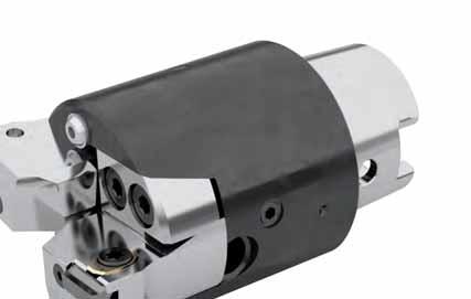
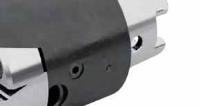
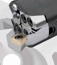


104 HOLLFELDER CUTTING TOOLS GA200-VARIO Boring system for diameters 44 mm mm 104 precise flexible innovative
105 Boring system GA200-Vario Features page Boring system for diameters mm page 108 Reductions, basic adapters, extensions page 109 Indexable inserts page 110 Solid carbide ISO indexable inserts page 111 A 50:1 Concept pre- and finish machining in one step page 112 unequal cutting edge spacing 170 page 113 Presetting device for GA200-Vario and accessories page vc Adjustment instruction page 116 Application example page


106 The new boring system GA200-VARIO for diameters from 44 to 130 mm Features: μm-precise diameter adjustment for fineboring thanks to insert holder with Hollfelder-Guhring tapered screw adjustment large adjustment range internal coolant supply is directed straight to the cutting edge different insert holders for fine- and rough boring unequal cutting edge spacing 170 adaptable to fit all kind of spindles and lengths rigid connection between basic adapter and interchangeable insert holder Advantages of the overall concept: roughing and finish machining with only one tool head due to progressive cutting process close tolerances can be maintained one basic adapter for different diameters no retraction marks because of unequal cutting edge spacing wide range of insert geometries and coatings available according to customer specifications 106


107 The boring system from Hollfelder-Gühring impresses with high flexibility and enormous accuracy Suitable insert holders and inserts are available for roughing as well as for fine machining. Depending upon the basic adapter the adjustment range is mm in Ø i.e. basic adapter 1 => D = mm basic adapter 5 => D = mm The basic adapters are adaptable/extendable thanks to the HSK-connections. HOLLFELDER-GÜHRING CUTTING TOOLS The tapered screw adjustment of the fine boring cartridges provide the possibility to μm-accurately adjust all insert diameters. The capability of this high-performance tooling system can be applied for a variety of machining tasks and is optimally suited for all different kinds of materials as well as for HSC machining. Features of the fine boring holder: - highly accurate, guide-like insert pocket - precision ground cutting insert - tapered screw for μm-accurate diameter adjustment - simple handling only two parts clamping set and adjustment element The advantages: - extreme operational smoothness and durable insert pockets - superior axial run-out and concentricity accuracy - extremely long tool life - excellent surface quality - simple adjustment in μm-range Further information regarding this adjustment system as well as instructions can be found on page
108 Boring system for diameters from mm H1 Holder for finishing H3 Holder for roughing 180 H3 Holder for roughing 150 H1 GA H2 GA H3 GA Ø D Ø D Ø D L1 L L A B C Basic adapter Fine boring holder Diameter D Length L1 H1 Holder for finishing Part no mm 27 mm GD R mm 27 mm GD R mm 27 mm GD R mm 27 mm GD R mm 35 mm GD R Holder for roughing Diameter D Length L1 H3 Holder for roughing 180 Part no mm 27,5 mm GD 09T3 0029R mm 27,5 mm GD 09T3 1184R mm 27,5 mm GD 09T3 1185R mm 27,5 mm GD 09T3 1186R mm 35,5 mm GD 09T3 2251R alternative Diameter D Length L1 H3 Holder for roughing 150 Part no mm 27,5 mm GD 09T3 0028R mm 27,5 mm GD 09T3 1181R mm 27,5 mm GD 09T3 1182R mm 27,5 mm GD 09T3 1183R mm 35,5 mm GD 09T3 2250R * balancing quality must be checked L1 Diameter D Shank Total length L GA basic adapter Part no. max. RPM* A B C mm HSK 40-C 55 mm 55,5 mm 55,5 mm GK mm HSK 50-C 60 mm 60,5 mm 60,5 mm GK mm HSK 63-C 60 mm 60,5 mm 60,5 mm GK mm HSK 63-C 60 mm 60,5 mm 60,5 mm GK mm HSK 63-C 73 mm 73,5 mm 73,5 mm GK Ordering example: Quantity Description Number Part no. 1 piece Basic adapter GK pieces Holder for roughing 150 GD 09T3 1182R L1 L piece Basic adapter GK pieces Holder for finishing GD R
109 Reductions, basic adapters and extensions Reductions HSK-A / HSK-C Part no Code HSK-A HSK-C d 1 SW d 3 l 1 d 3 d 1 40, , , , l 1 Basic adapters SK / HSK-C SK to DIN form AD Part no Code SK HSK-C d2 d1 SW l 1 l 1 d 1 40, , , , , , Extensions HSK-A / HSK-C Part no Code HSK-A / HSK-C d 1 SW l 1 d 3 l 1 d 1 / d 3 80, , , , , Extensions HSK-C Part no Code HSK-C d 1 SW d 3 l 1 d 1 / d 3 50, , , l 1 Further information can be found in the Guhring catalogue GM
110 1,8 11 4,5 Indexable inserts precision ground for GA200-Vario boring systems Insert W L 4,5 15 4,5 2,5 11 R 80 with wiper geometry AL 9 Part no. Part no. Part no uncoated coated coated Code Drawing no. R AL K10 G12 G16 40,900 W L 0, ,901 W L 0, ,902 W L 0, ,903 W L 0,4 16 Part no. Part no. Part no with wiper geometry uncoated coated coated Code Drawing no. R AL K10 G12 G16 40,900 W L 0, ,901 W L 0, ,902 W L 0, ,903 W L 0,4 16 Insert W L PCD- / CBN-tipped 4,5 15 R 80 with wiper geometry 3 Part no. Part no Code Drawing no. R AL PCD 10 CBN 40 40,930 W L 0, ,931 W L 0,2 0 40,932 W L 0,4 0 40,933 W L 0,8 0 Part no. with wiper geometry Code Drawing no. R AL PCD 10 40,930 W L 0, ,931 W L 0,2 0 40,932 W L 0,4 0 ex stock on request 110
111 80 80 Solid carbide ISO indexable inserts precision ground with standard chipbreaker 10, form C R AL 9,53 7 9,67 3,97 Part no. Part no. Part no. Part no uncoated TiN TiAlN SuperA Proton Code ISO code R AL K10 K10 K10 K10 93,020 CCHX 09T302 L 116 0, ,040 CCHX 09T304 L 116 0, ,080 CCHX 09T308 L 118 0,8 10 Part no. Part no. Part no. Part no uncoated TiN TiAlN SuperA Proton Code ISO code R AL P40 P40 P40 P40 93,020 CCHX 09T302 L 116 0, ,040 CCHX 09T304 L 116 0, ,080 CCHX 09T308 L 118 0,8 10 with standard chipbreaker 18, form C R AL 9,53 7 9,67 3,97 Part no. Part no. Part no uncoated TiN Proton Code ISO code R AL K10 K10 K10 93,020 CCHX 09T302 L 216 0, ,040 CCHX 09T304 L 216 0, ,080 CCHX 09T308 L 218 0,8 18 Part no. Part no. Part no. Part no uncoated TiN Proton uncoated Code ISO code R AL P40 P40 P40 P10 93,020 CCHX 09T302 L 216 0, ,040 CCHX 09T304 L 216 0, ,080 CCHX 09T308 L 218 0,

112 Concept: pre- and finish machining in one step Technology and advantages The different roughing holders H2 & H3 were each designed 0.5 mm longer (L1) than the corresponding fine boring holders H1. Therefore, for example, it is possible to fit two different holders to a basic adapter. In the following, the diameter range 44 mm 55 mm is shown as an example: 1x GD 09T3 0029R H2 holder for roughing 55,5 27,5 GK Ø44-Ø55 mm Ø D2 Ø D1 i.e. Ø 50 mm i.e. Ø 49,5 mm D1 roughing D2 finishing 1x GD R H1 holder for finish machining The roughing insert D1 is adjusted 0.5 mm smaller in diameter than the finishing insert D2. This is set to the final required measurement. During machining, the roughing insert leads the finishing insert by 0.5 mm due to the longer holder. progressive cutting process Z eff = 1 Advantages: Roughing and finish machining with one basic adapter in one cut the roughing operation can possibly be omitted For the production of holes with high geometric requirements very high surface quality Maintaining straightness is possible even during interrupted machining processes. 112
113 Concept: unequal cutting edge spacing 170 Technology and advantages Thanks to the 170 insert spacing the tool can travel up to 0.7 mm in the Y-direction following the conclusion of the finishing operation. Hereby, a clearance of approximately 0.06 mm between hole and insert is created! The tool can now be drawn from the hole without the surface being damaged by scoring marks caused during retraction! higher feed rate through Z eff = 2 1. Fine machining of hole with two effective inserts. The inserts are turned towards each other by Orientated spindle stop Off-set for retraction A 170 Y-direction 5 3. Tool travels in Y-direction Tool free! A 50:1 Created clearance between hole and insert Bore in component / work piece diameter Cutting tool path 4. Tool retraction in rapid traverse no score marks! 113

114 Presetting device for GA200-Vario and A setting device was specificly developed for the pre-setting of GA200-Vario tools. Presetting device Part no The scope of delivery includes a digital dial gauge. It can be moved horizontally with a rail guide. The large and clear digital display allows easy reading of the measuring value. By using different setting adapters any tool size can be adjusted with the same setting device. L1 Ø 80 h7 Ø 100 Setting adapter (intermediate flange + adapter flange) Shank for diameter D Length L1 Part no. HSK 40-C mm 68 mm HSK 50-C mm 63 mm HSK 63-C mm 63 mm
115 required accessories In addition, the following measuring masters are required. All diameters are covered. Setting screw with nut L Base body Ø D2 Ø D1 L Measuring diameter D3 and D4 only with part no Measuring master Shank Measuring diameter D1, D2, D3, D4 Length L Part no. HSK 40-C 44 mm, 50 mm 55 mm HSK 50-C 55 mm, 62 mm 60 mm HSK 63-C 69 mm, 80 mm, 90 mm, 100 mm 60 mm HSK 63-C 106 mm, 120 mm 73 mm The following setting key enables the customer to re-adjust the fine boring tool during the machining process without having to remove it from the machine. Setting key for the adjustment of insert type W4090 SW 1,5 107 ( ) ,0 = Setting key (incl. SW 1.5 bit) Part no Ordering example: Quantity Description Part no. 1 piece Adjustment tool piece Setting adapter HSK 50-C piece Measuring master HSK 50-C
 Tighten the clamping screw (KS) with torque wrench to 1 Nm max (picture 2) Adjust both holders using screw (VS) to within Ø 0.")
 has to be adjusted according to the requested dimension.")
116 Adjustment instruction Adjustment of holder H1 for fine boring The top of the tapered screw (V) must be even flush with the top of the holder body (picture 1) Install a new insert into the pocket seat and slightly tighten the clamp set (S) Tighten the clamping screw (KS) with torque wrench to 1 Nm max (picture 2) Adjust both holders using screw (VS) to within Ø ,25 mm of required nominal diameter Tighten the clamping screw KS to required torque specification KS M4x16 (12.9) KS M6x25 (12.9) Torque value 5.1 Nm 17.6 Nm V S 1 KS VS 2 The roughing tool holder (H2, H3) has to be adjusted according to the requested dimension. Changing fine boring inserts Disassembly/Assembly: Loosen the clamping set S (1 to 2 turns) and remove the worn insert Clean the insert pocket Unscrew the tapered screw (V) 1 to 2 full rotations Insertion of new insert Press insert into the pocket, hold and pre-tension clamping set S to Ncm Assembly: Fine boring inserts need be adjusted within approximately 0,05 mm to the nominal dimension Tighten the clamp set (S) to required torque value Adjust the insert to the required machining diameter via tapered screw. It is not necessary to re-tighten the clamping set! Tightening torques for clamping sets Tool type Clamping set S Torque Torx size Taper screw V Torque wrench fixed DSF (Ncm) Code H 4090 E Tx 15 E ,450 Torque wrench ,200 adjustable DS ,000 Assembly tools SW 3 resp. 5 for KS Part no Code 3,000 resp. 5,000 SW 3 resp. 5 for VS Part no Code 3,000 resp. 5,000 SW 1,5 for V Part no Code 1,


117 Application example Finish machining of Pin bore on connecting rod Workpiece connecting rod Material 36MnVS4 Tool GA200-Vario fine boring tool Ø mm Number of teeth 2 Insert acc. to customer specification Cutting grade HM with PROTON coating TiAlN Cutting speed vc = 250 m/min Number of revolutions n = rev./min Feed rate 169 mm/min Feed rate per tooth 0.07 mm Cutting depth 0.3 mm (0.6 in diameter) Coolant yes, internal 117


118 HOLLFELDER CUTTING TOOLS Drill- & Chamfering tools 118 precise flexible innovative
119 Drill / Chamfering tools versatile HOLLFELDER-GÜHRING CUTTING TOOLS The new Drill / Chamfering tools are applicable for versatile machining tasks and a wide varity of materials. The features: Use in standard hydraulic expansion chucks Use of standard solid carbide drills (DIN 6537 L/K) 3xD, 5xD, 7xD 3 different chamfering angles as standard available Standard inserts in carbide (uncoated and coated) as well as in PCD available Advantages by use of these tools: High runout accuracy due to use in hydraulic expansion chucks High tool life on drills and inserts One tool holder for different chamfering angles Reduced amount of tool bodies Easy handling, assembly and setup Reduced non-productive times Suitable for all standard hydraulic expansion chucks No additional costs for special chucks 119

120 Drill / Chamfering tools Possible drill-adapter combinations Drill Drill Drill 3xD 5xD 7xD T T T DIN 6537 K DIN 6537 L Twisted Twisted Twisted Drawing number FB Insert SL SL Ø B from - to from - to from - to H R 1.8 W L H R 1.8 W L H R 1.8 W L H R 1.8 W L H R 1.8 W L H R 1.8 W L H R 2.5 W L H R 2.5 W L H R 1.8 W L H R 1.8 W L H R 1.8 W L H R 1.8 W L H R 2.5 W L H R 2.5 W L H R 2.5 W L H R 2.5 W L Ordering example: Drill-Ø = 6.2 mm, Drilling depth = 22 mm, Chamfer = 1x45, Hydraulic chuck-ø = 20mm reading from the table: Drawing number = H R, the drawing number reading from the table of the right side shows the Ordering number = Part.Nr. + Code ,
121 Drill / Chamfering tools Drill length L SL FW Ø D1 max. Ø B Ø d Ø D Ø A T FB max. L3 L2 L Code Drawing number Ø B FB max. Ø D Ø d Ø A L L1 L2 L3 Ø D 1max Insert L 6,012 H R W L 8,012 H R W L 6,020 H R W L 8,020 H R W L 10,020 H R W L 12,020 H R W L 6,032 H R W L 8,032 H R W L 10,032 H R W L 12,032 H R W L 14,020 H R W L 16,020 H R W L 14,032 H R W L 16,032 H R W L 18,032 H R W L 20,032 H R W L Spare parts Code Drawing number Clamping set for Tx 2,000 E4890 H ,500 E4991 H Ordering example: Part number + Code = Ordering number e.g. Clamping set for H = Ordering number ,


. More information can be found in the corresponding GUHRING catalogs.")
122 Inserts Application recommendations Cutting material Grade composition Workpiece material Grade code Substrate Coating Steel Stainless steel Cast iron Non ferrous materials Heavy machinable materials K10 K10 uncoated With chipbreaker G12 K10 TiAlN Multilayer PVD With chipbreaker G16 P40 TiAlN Multilayer PVD With chipbreaker PCD 10 Grain size 10 μm Without chipbreaker = very good applicable = applicable = not applicable Further cutting material, coatings and geometries on request. Recommended drills and hydraulic chucks All drill / chamfering adapters are especially designed for the hydraulic chuck line of the GUHRING GM 300 program and the solid carbide drill line RT 100 (DIN 6537 L/K). More information can be found in the corresponding GUHRING catalogs. WERKZEUGAUFNAHMEN 2015 GM 300 WERKZEUGAUFNAHMEN UND SPANNMITTEL 122 GM 300
123 Inserts The cutting data recommendations in the table are guide values and depend to a high degree on the stability of the machine, fixture and workpiece. Cutting group Material group Composition / Structure Tensile strength RM (MPa) Hardness HB HRC Cutting speed Recommended cutting grade Feed rate fz mm/z vc m/min W W C = annealed, long cut G C = annealed, short chip Unalloyed steel C = annealed, long cut Cast steel C = annealed, short chip Machining steel C = tempered C = annealed C = tempered annealed Low-alloy steel Cast steel tempered Machining steel tempered tempered High-alloy steel Cast steel annealed High-alloy tool steel hardened and tempered Stainless steel ferritic/martensitic annealed and cast steel martensitic austenitisch quenched G16 Stainless steel 14.2 austenitic/ferritisch (duplex) perlitic/ferritic K10/G12 Grey cast iron 16 perlitic (martensitic) Cast iron with ferritic nodular cast iron perlitic ferritisch Malleable 20 perlitic Aluminium not heat treatable K10/PKD forging alloys aushärtbar/ausgehärtet <12% Si not heat treatable Aluminium casting alloys <12% Si heat treatable/heat treated >12% Si not heat treatable Copper Machined alloys, Pb >1% K10/G12 27 Copper alloys CuZn, CuSnZn (bronze, brass) Cu, lead free Copper/electrolyte copper Non metallic Duroplastic -200 K10/PKD materials Reinforced materials Fe-based annealed G16 32 heat treated Heat treatable alloys Ni- or Co-based annealed heat treated cast Pure titanium K10 Titanium alloys 37 Alpha-beta alloys
124 Inserts Carbide inserts uncoated / coated PCD inserts R F B max. h R F B max. h FW FW AL AL F B max FW AL R h Cutting grade Code Drawing nr. max. Chamfer width Chamfer angle Rake angle Radius Heigth K10 G12 G16 PKD 10 20,060 W L ,060 W L ,061 W L ,061 W L ,062 W L ,062 W L ,063 W L ,063 W L ,064 W L ,064 W L ,065 W L ,065 W L ex stock Ordering example: e.g. 30 PCD 10 Chamfering insert for adaptor H reading from the table: Drawing number = W L PCD 10, Ordering number = + Code ,

125 Assembly instruction Changing the insert Disassembly Loosen clamp set (1 to 2 turns) and remove worn insert Clean pocket seat Assembly Put new insert into pocket seat Press insert into the pocket seat while slightly tightening the clamp set Push insert against the drill, therefore place 0.03 mm feeler gauge between insert and drill Hold insert in position and tight down clamp set with recommended torque Clamp set Clamping set for Tx Torque (Ncm) E4890 H E4991 H Torque wrenches Drawing number Version Tx Ncm E5000 adjustable E5001 adjustable E fixed 6 70 E fixed Ordering numbers for spare parts see pages

126 HOLLFELDER CUTTING TOOLS Turning tools Boring bars / cartridges for the internal machining 126 precise flexible innovative
127 Boring bars with minimum working diameter from 5 mm page 128 Technical information page / 95 approach angle - shank with clamping flange page / 95 approach angle - shank round version page with minimum working diameter from 6 mm 90 / 95 approach angle - with carbide shank, internal coolant supply page with minimum working diameter from 6 mm Copying boring bars with minimum working diameter from 12 mm 93 / approach angle page 135 Spare part boring bars page 136 Special tooling page 137 Inserts Grade selection - carbide, carbide coated, PCD, CBN page 138 Insert program from page 139 v c Application recommendations page 143 Cutting data recommendations page 144 Form Request for special tooling page
. This range of boring bars starting from 5 mm will satisfy all your requirements.")

 relations.")

128 Boring bars starting from 5 mm working diameter versatile HOLLFELDER-GÜHRING CUTTING TOOLS creates the basis for a versatile production on turning machines (lathes). This range of boring bars starting from 5 mm will satisfy all your requirements. The various product ranges are fitted to each other in such a way as to offer a wide range of applications to the user. Depending on the individual application you can choose among boring bars with steel- or carbide shanks as well as among different insert geometries and approach angles. The boring bars with carbide shank and internal coolant supply in particular enable the use of large L/D (length-diameter) relations. The precisionground inserts offer the highest degree of precision and cutting performance independent of the geometry of the boring bar. The positive chipbreaker geometries of the inserts are responsible for an advantageous chip forming, reduced machining force on the insert, excellent chip flow and as a result a superior process stability even under difficult machining conditions and at unstable workpieces. 128

129 Boring bars starting from 5 mm working diameter The insert clamping and the geometry of the pocket seat is designed in a way that it protects the second cutting edge of the insert within the insert pocket and avoids the destruction or damage that might be caused by the impact of evacuated chips. Clamping and releasing the insert is handled by means of a single clamp screw and is therefore very easy; at the same time the requirement for stock-keeping of spare-parts is reduced to a minimum. Our mini-boring bars are also perfectly suitable for every kind of form recesses. In customer specific requirements the operational possibilities of our standard boring bars can on request beenormously increased by means of special form inserts. e.g. for form recesses or grooveing Please use our inquiry sheet on page 130 for requests of customer-specific special tooling solutions. pocket seat highly accurate by EDM internal coolant supply precision ground insert with positive cutting geometrie Clamping set (Clamping element with clamping screw) unhampered chip flow carbide shank 129
130 Boring bars starting from 5 mm working diameter 90 / 95 approach angle, 80 corner angle Shank with clamping flange Ø Dmin 90 f b 95 Right-hand cutting version left-hand cutting version inv. Ø d g6 80 L L1 h Code Drawing nr. Ø D min Ø d f b h L 1 L Inserts* 90 approach angle 5,000 H R W L 6,000 H R ,000 H R ,000 H R approach angle 5,001 H R ,001 H R ,001 H R ,001 H R Code Drawing nr. Ø D min Ø d f b h L 1 L Inserts* 90 approach angle 5,000 H L W R 6,000 H L ,000 H L ,000 H L approach angle 5,001 H L ,001 H L ,001 H L ,001 H L *Please note: Left-hand boring bars have to be fitted with right-hand inserts and right-hand boring bars with left-hand inserts! ex stock Ordering example: 1 piece H R = Ordering number: ,000 Shank with clamping flange Spare parts page 136 Grade selections and insert geometries page 138 v c 130
131 Boring bars starting from 6 mm working diameter 90 / 95 approach angle, 80 corner angle Shank round version Right-hand cutting version left-hand cutting version inv. Ø Dmin f b Ø d g6 L1 80 L Code Drawing nr. Ø D min Ø d f b L 1 L Inserts* 90 approach angle 6,000 H R W L 8,000 H R W L 10,000 H R ,000 H R ,000 H R W L 20,000 H R ,000 H R ,000 H R W L 40,000 H R approach angle 6,001 H R W L 8,001 H R W L 10,001 H R ,001 H R ,001 H R W L 20,001 H R ,001 H R ,001 H R W L 40,001 H R *Please note: Left-hand boring bars have to be fitted with right-hand inserts and right-hand boring bars with left-hand inserts! ex stock on request Ordering example: 1 piece H R = Ordering number: ,000 v c Application recommendations page 144 Form Request for customer specific tools page 148 Shank round version / /
132 Boring bars starting from 6 mm working diameter 90 / 95 approach angle, 80 corner angle Shank round version Right-hand cutting version left-hand cutting version inv. Ø Dmin f b Ø d g6 L1 80 L Code Drawing nr. Ø D min Ø d f b L 1 L Inserts* 90 approach angle 6,000 H L W R 8,000 H L W R 10,000 H L ,000 H L ,000 H L W R 20,000 H L ,000 H L ,000 H L W R 40,000 H L approach angle 6,001 H L W R 8,001 H L W R 10,001 H L ,001 H L ,001 H L W R 20,001 H L ,001 H L ,001 H L W R 40,001 H L *Please note: Left-hand boring bars have to be fitted with right-hand inserts and right-hand boring bars with left-hand inserts! ex stock on request Ordering example: 1 piece H L = Ordering number: ,000 Shank round version / / Spare parts page 136 Grade selections and insert geometries page 138 v c 132
133 Boring bars starting from 6 mm working diameter 90 / 95 approach angle, 80 corner angle Carbide shank with internal coolant supply 95 Right-hand cutting version left-hand cutting version inv. 90 Coolant outlet D min f b d g6 80 L L Code Drawing nr. Ø D min Ø d f b L 1 L Inserts* 90 approach angle 6,000 HH R W L 8,000 HH R W L 10,000 HH R ,000 HH R ,000 HH R W L 20,000 HH R approach angle 6,001 HH R W L 8,001 HH R W L 10,001 HH R ,001 HH R ,001 HH R W L 20,001 HH R *Please note: Left-hand boring bars have to be fitted with right-hand inserts and right-hand boring bars with left-hand inserts! ex stock Ordering example: 1 piece HH R = Ordering number: ,000 v c Application recommendations page 144 Form Request for customer specific tools page 148 Internal coolant supply shank round version /
134 Boring bars starting from 6 mm working diameter 90 / 95 approach angle, 80 corner angle Carbide shank with internal coolant supply 95 Right-hand cutting version left-hand cutting version inv. 90 Coolant outlet D min f b d g6 80 L L Code Drawing nr. Ø D min Ø d f b L 1 L Inserts* 90 approach angle 6,000 HH L W R 8,000 HH L W R 10,000 HH L ,000 HH L ,000 HH L W R 20,000 HH L approach angle 6,001 HH L W R 8,001 HH L W R 10,001 HH L ,001 HH L ,001 HH L W R 20,001 HH L *Please note: Left-hand boring bars have to be fitted with right-hand inserts and right-hand boring bars with left-hand inserts! ex stock Ordering example: 1 piece HH L = Ordering number: ,000 internal coolant supply shank round version / Spare part page 136 v c Grade selections and insert geometries page
135 Copying boring bars starting from 12 mm working diameter 93 / approach angle, 55 corner angle Shank round version Right-hand cutting version left-hand cutting version inv. 93 D min f b d g6 t L1 55 L Code Drawing nr. Ø D Ø d f b t L 1 L Inserts* 93 approach angle 12,000 H R W L 16,000 H R ,500 H R Einstellwinkel 12,001 H R ,001 H R ,501 H R Code Drawing nr. Ø D Ø d f b t L 1 L Inserts* 93 approach angle 12,000 H L W R 16,000 H L ,500 H L approach angle 12,001 H L ,001 H L ,501 H L *Please note: Left-hand boring bars have to be fitted with right-hand inserts and right-hand boring bars with left-hand inserts! ex stock Ordering example: 1 piece H R = Ordering number: ,000 v c Application recommendations page 144 Form Request for customer specific tools page 148 Shank round version
136 Boring bars starting from 5 mm working diameter Spare parts for boring bars for copying bars Type H1733, H/HH 8003, 8005, 8008, H 8012 Type H 5506 Tx Tx SW only for type H 8012 S Double thread screw only for type H 8012 S Clamping element H 8012 Ordering number Ordering number for type S Tx / SW for type S Tx / SW H R/L E 3441 Tx 5 H R E 1092 Tx 8 H R/L E 1031 Tx 6 H L E 1114 Tx 8 H R/L E 1014 Tx 8 H R/L E 1010 Tx 8 HH R/L E 1031 Tx 6 HH R/L E 1014 Tx 8 HH R/L E 1010 Tx 8 H R/L E 1001 / E 1030 SW 2,5 Please note: Clamping set S contains: 1 clamping element, 1 retainer ring, 1 clamping screw S Tx SW Clamping set Torx screw driver Hex drive key Availability according to valid price list Ordering numbers for spare parts see page
 Sint D11 (sintersteel metall) Plunging tool for turning machines Number of teeth z")

137 Customer spec. turning tools Application examples Application: Camshaft regulator Workpiece Material Tool Camshaft regulator (DIN) Sint D11 (sintersteel metall) Plunging tool for turning machines Number of teeth z = 2 / effective 1 adjustable Insert Cutting grade acc. to customer specific. H06 carbide coated Cutting speed V c = 220 m/min (Ø 29.1) Number of revolutions n = min -1 Feed rate Feed rate per tooth Depth of cut Coolant V f = 241 mm/min f z = 0.1 mm ~4.5 mm yes, internal coolant Application: plunge turning - profile recess Workpiece Profile shaft axially adjustable with cartridge Material Tool (DIN) 9 S Mn 28K Plunging tool adjustable Number of teeth z = 2 / effective 1 Insert Cutting grade Cutting speed acc. to customer specific. H06 carbide coated V c = 120 m/min Number of revolutions n = 764 min -1 Feed rate Feed rate per tooth Depth of cut Coolant V f = 76 mm/min f z = 0.1 mm 2 mm yes, external 137
138 Application recommendations Inserts precision ground Grade matrix Grade selection Chipbreaker recommendation Carbide / carbide coated / PCD / CBN Chipbreaker for boring bars starting from 5 mm working diameter Cutting material Grade composition Workpiece material Grade code Substrat Coating Steel Stainless steel Cast iron Nonferous materials Heavy machinable materials Hardened steel P10 P10 uncoated n Chipbreaker P40 P40 uncoated n Chipbreaker K10 K10 uncoated n n n Chipbreaker * H02 K10 TiAlN PVD n t n t n Chipbreaker H06 P40 TiAlN PVD n n t n n Chipbreaker H25 P40 TiN CVD n Chipbreaker H26 P40 TiN PVD t n n Chipbreaker PCD 10 Grainsize 10μm Chipbreaker CBN t n t n Chipbreaker = very good applicable = applicable = not applicable * = for Titanium t = dry n = wet Further cutting material, coatings and geometries on request
139 Indexable inserts precision ground for boring bars starting from 5 mm working diameter Insert W L/R* Carbide / carbide coated / PCD 10 1,7 15 1,7 0,8 11 R AL 3,25 80 Left-hand cutting versions right-hand cutting versions inv uncoated coated Code Drawing nr. R AL P10 P40 K10 H02 H06 H26 17,330 W L ,331 W L ,332 W L ,333 W L ex stock on request uncoated coated Code Drawing nr. R AL P10 P40 K10 H02 H06 H26 17,330 W R ,331 W R ,332 W R ,333 W R Code Drawing nr. R AL PCD 10 17,330 W L ,331 W L ,332 W L Code Drawing nr. R AL PCD 10 17,330 W R ,331 W R ,332 W R *Please note: Left-hand boring bars have to be fitted with right-hand inserts and right-hand boring bars with left-hand inserts! Ordering example: 1 piece W L H02 = Ordering number: ,330 Insert carbide coated W L Insert PCD 10-fullface W L 139
140 Indexable inserts precision ground for boring bars starting from 6 mm working diameter Insert W L/R* Carbide / carbide coated Left-hand cutting versions right-hand cutting versions inv. B AL 11 3 R uncoated coated Code Drawing nr. R B AL P10 P40 K10 H25 H26 80,030 W L ,031 W L uncoated coated Code Drawing nr. R B AL P10 P40 K10 H25 H26 80,030 W R ,031 W R Insert W L/R* Carbide / carbide coated 2,5 15 2,5 Left-hand cutting versions right-hand cutting versions inv. B AL 11 4,5 R uncoated coated Code Drawing nr. R B AL P10 P40 K10 H25 H26 80,050 W L ,051 W L ,052 W L uncoated coated Code Drawing nr. R B AL P10 P40 K10 H25 H26 80,050 W R ,051 W R ,052 W R *Please note: Left-hand boring bars have to be fitted with right-hand inserts and right-hand boring bars with left-hand inserts! ex stock v c on request Ordering example: 1 piece W L H26 = Ordering number: ,030 Application recommendations page 143 v c Grade selections and insert geometries page 138 Insert carbide uncoated W L W L 140
141 Indexable inserts precision ground for boring bars starting from 6 mm working diameter Insert W L/R* Carbide / carbide coated Left-hand cutting versions right-hand cutting versions inv. B AL 11 7,4 R 80 ex stock v c Insert W L/R* Carbide / carbide coated Left-hand cutting versions right-hand cutting versions inv. on request Application recommendations page 143 v c 5, uncoated coated Code Drawing nr. R B AL P10 P40 K10 H25 H26 80,080 W L 0,2 1, ,081 W L 0,4 2, ,082 W L 0,8 2, ,083 W L 0,2 2, ,084 W L 0,4 2, uncoated coated Code Drawing nr. R B AL P10 P40 K10 H25 H26 80,080 W R 0,2 1, ,081 W R 0,4 2, ,082 W R 0,8 2, ,083 W R 0,2 2, ,084 W R 0,4 2,6 24 B 5,8 AL 8 Grade selections and insert geometries page , uncoated coated Code Drawing nr. R B AL P10 P40 K10 H25 H26 80,120 W L 0,4 2, ,121 W L 0,8 2, ,122 W L 0,4 3, ,123 W L 0,8 3, uncoated coated Code Drawing nr. R B AL P10 P40 K10 H25 H26 80,120 W R 0,4 2, ,121 W R 0,8 2, ,122 W R 0,4 3, ,123 W R 0,8 3,6 24 *Please note: Left-hand boring bars have to be fitted with right-hand inserts and right-hand boring bars with left-hand inserts! 8 R 80 Insert carbide coated W L W L 141
142 Indexable inserts precision ground for boring bars starting from 12 mm working diameter Inserts W L/R* Carbide / carbide coated R Left-hand cutting versions right-hand cutting versions inv. B AL 6, uncoated coated Code Drawing nr. R B AL P10 P40 K10 H25 H26 55,060 W L ,061 W L ,062 W L ,063 W L uncoated coated Code Drawing nr. R B AL P10 P40 K10 H25 H26 55,060 W R ,061 W R ,062 W R ,063 W R *Please note: Left-hand boring bars have to be fitted with right-hand inserts and right-hand boring bars with left-hand inserts! ex stock v c on request Ordering example: 1 piece W L H25 = Ordering number: ,060 Application recommendations page 143 Grade selections and insert geometries page 138 Insert carbide coated W L v c 142
143 Application recommendations Inserts for boring bars Guide values for surface finish In order to select the right feedrate per tooth (fz) please pay also attention to the table below Guide values for surface finish. Guide values for surface finish relative to feedrate and corner radius fz (mm) 0,4 0,3 Corner radius 1,2 mm Corner radius 0,8 mm Feedrate per tooth 0,2 0,1 Corner radius 0,4 mm Corner radius 0,2 mm 0,05 Corner radius 0,05 mm 3,2 0,63 4 6,3 1,25 7 Surface finish 10 2,5 13 3, , ,3 30 Rz μm Ra μm Rt μm 143
144 Cutting data recommendations The cutting data recommendations in the table are guide values and depend to a high degree on the stability of the machine, fixture and workpiece. Cutting groups 144 Material group Composition / structure Tensile strength Hardness Cutting speed recom. Cutting grade feed rate fz mm/z RM (MPa) HB HRC V c m/min Insert type W W W W W W C = annealed, long cutt H26/H C = annealed, short chip Unalloyed steel C = annealed, long cutt Cast steel C = annealed, short chip Machining steel C = tempered C = annealed C = tempered annealed Low-alloy steel Cast steel tempered Machining steel tempered tempered High-alloy steel Cast steel annealed High alloy tool steel hardened and tempered Stainless steel ferritic/martensitic annealed and cast steel martensitic Stainless steel austenitic quenched H26/H austenitic/ferritic (duplex) perlitic/ferritic H02/K10 Grey cast iron 16 perlitic (martensitic) Cast iron with ferritic H26/H06/ 18 nodular cast iron perlitic H02 19 ferritic H26/H06 Malleable 20 perlitic Aluminium not heat treatable K10/PKD forging alloys heat treatable/heat treated <12% Si not heat treatable Aluminium 24 <12% Si heat treatable/ heat treated casting alloys 25 >12% Si not heat treatable PKD Copper machined alloys, Pb >1% H02/K10 27 copper alloy CuZn, CuSnZn (bronze, brass) Cu, lead free copper/electrolyte copper Non metallic Duroplastic -200 K10/PKD materials Reinforced materials Fe-based annealed H26/H06 32 heat treated Heat resistand alloys Ni- or Co-based annealed heat treated cast Pure titanium K10 Titanium alloys 37 Alpha-beta alloys Hardened steels CBN
145 Spare parts Coolant pipes Adjustment screws Drawing nr. Code Drawing nr. Code E ,032 E ,003 E ,040 E ,004 E ,050 E ,401 E ,063 E ,402 E ,080 E ,403 E ,100 Axial adjustment screws for cartridges Socket wrenches for coolant pipes Drawing nr. Code Drawing nr. Code E ,000 E ,000 E ,000 E ,000 E ,000 E ,000 E ,000 E ,000 E ,001 E ,000 E ,000 Pushing pins Drawing nr. Code Tapered adjustment screws E ,800 Drawing nr. Code E ,300 E ,002 E ,500 E ,000 E ,000 E ,500 E ,601 Setup fixture for mini boring bars E ,001 Drawing nr. Code E ,600 X ,000 Adjustment screws Operating key Drawing nr. Code Drawing nr. Code E ,501 E ,000 E ,502 E ,001 Clamp screws for cartridges E ,002 Drawing nr. Code E ,003 E ,100 E ,005 E ,120 E ,001 E ,160 E ,002 Ordering example: E = Ordering number ,032 (part nr. + code) 145
146 Spare parts Disk springs for cartridges Torque wrenches adjustable Drawing nr. Code Drawing nr. Code E ,500 E ,200 E ,000 E ,000 E ,000 E ,810 Threaded pins Torque wrenches not adjustable Drawing nr. Code Drawing nr. Code E ,401 E ,450 E ,402 E ,700 E ,403 E ,400 E ,001 E ,450 E ,002 E ,150 E ,003 E ,800 E ,004 E ,120 E ,005 E ,151 E ,006 E ,501 Torx interchangeable blade E ,502 Drawing nr. Code E ,503 Tx ,000 E ,504 Tx ,000 E ,505 E ,001 Torx-bits E ,002 Drawing nr. Code E ,003 Tx5-bit ,000 E ,004 Tx6-bit ,000 E ,005 Tx7-bit ,000 E ,006 Tx7-bit long ,000 E ,007 Tx8-bit ,000 Tx9-bit ,000 Torx wrenches Tx10-bit ,000 Drawing nr. Code Tx15-bit ,000 Tx ,001 Tx ,001 Bit universal holder Tx ,001 Drawing nr. Code Tx ,001 Tx-bit ,300 Cranked Torx wrench Drawing nr. Code Tx ,002 Ordering example: E = Ordering number ,500 ( + Code) 146
147 Spare parts Allen wrenches Clamping sets for drill and chamfering tools Drawing nr. Code Drawing nr. Code SW0, ,700 E ,000 SW0, ,900 E ,500 SW1, ,300 SW1, ,500 Eccentric pins SW2, ,000 Drawing nr. Code SW2, ,500 E ,501 SW3, ,000 E ,001 SW4, ,000 SW5, ,000 Assembly crease for eccentric pins SW6, ,000 Drawing nr. Code E ,000 Clamping sets for countersinking tools, cartridges and boring bars Coolant screws for milling cutters Drawing nr. Code Drawing nr. Code E ,000 E ,001 E ,000 E ,001 E ,501 E ,001 E ,000 E ,000 E ,002 E ,000 E ,500 E ,000 E ,500 E ,000 E ,001 E ,000 E ,502 E ,000 E ,601 E ,001 E ,000 E ,000 E ,602 E ,001 E ,600 Adapter for milling cutters Clamping sets for milling cutters Drawing nr. Code Drawing nr. Code E ,800 E ,500 E ,000 Clamping screw E ,501 Drawing nr. Code E , , ,500 Ordering example: SW 5.0 = Ordering number ,000 ( + Code) Adjustment screw Drawing nr. Code ,
148 HOLLFELDER-GÜHRING CUTTING TOOLS Wertachstraße 27 D Nürnberg Germany Telefon +49 (0) 911 / Fax +49 (0) 911 / info@hollfelder-guehring.de Internet: Inquiry form for special tooling HOLLFELDER CUTTING TOOLS Customer : Date : Contact person : Phone : Street : Fax : Town/Postal code : Workpiece : Drawingnumber : Material : Hardness/tensile strength: Machining : Into solid Blind hole Pre cast Through hole Pre bored Continous cut Interrupted cut Highly interrupted cut Others Required surface finish : Ra = Rz = Others : Stock : mm In radius In diameter a p = a e = Fixture : Stable Instable Very instable Interference : No Yes => if yes mm Machine : MC Transferline Lathe Turn / milling center Boring head Multi-spindle Spindle : Steep taper DIN Size HSK DIN Size Others : Internal coolant : Yes No max. Rpm : Power : kw Tool : Right-hand cutting Left-hand cutting Rotating Non rotating Face milling cutter Groove and end milling cutter Disc milling cutter Others : Shank style / Form : Size : Tool balanced : No Yes => if yes, balancing grade G 1/min at Necessary cutting data: v c = m/min f= mm/u mm/z mm/min Coolant : Internal External Without Remarks : 148 Emulsion Oil Mist Coolant Dry

149 HOLLFELDER-GÜHRING CUTTING TOOLS Wertachstraße 27 D Nürnberg Germany Telefon +49 (0) 911 / Fax +49 (0) 911 / info@hollfelder-guehring.de Internet: Inquiry form for HPC special milling cutters HOLLFELDER CUTTING TOOLS Please complete the enquiry form and fax: +49 (0) 911 / or scan and send direct to info@hollfelder-guehring.de An online enquiry can be found at Company name/no. if available new Contact customer Address Town/post code Telephone Fax Date Signature Ø D 2 HSK-A HSK-C Ø D HSK- SK DIN BT CAT L 1 Workpiece Width of cut (ae) Maximum no. of teeth Material IC (bar) Reduced no. of teeth Rough milling cutter Allowance (ap) MQL 1 channel Maximum tool weight Finish milling cutter Surface finish (Rz) MQL 2 channel 149
150 Note HOLLFELDER CUTTING TOOLS 150

151 Our innovative tooling systems are used all over the world in many areas in the metal cutting industry. Both the highly precise standard tools which can be used flexibly as well as our customer specific innovative tooling solutions qualify us as a reliable partner in the metal machining industry. We increase your productivity with our extensive experience and specific know-how. Call us, we will also meet your requirement! The result is economical, precise and of high quality. HOLLFELDER CUTTING TOOLS... precise... flexible... innovative HOLLFELDER-GÜHRING CUTTING TOOLS Wertachstraße 27 D Nürnberg Germany Telefon + 49 (0) 911 / Fax + 49 (0) 911 / info@hollfelder-guehring.de Internet:
HOLLFELDER CUTTING TOOLS
 HOLLFELDER CUTTING TOOLS HOLLFELDER-GÜHRING CUTTING TOOLS Your competent partner in the area of metal chip removal. At our two company locations in Nuremberg und Zorbau (Germany) we design and manufacture
HPC FACE MILLS for rough and finish machining
 HOLLFELDER CUTTING TOOLS THE ORIGINAL HPC FACE MILLS for rough and finish machining THE ULTIMATE EVOLUTION! AXIALLY CLOSED CHIP FLUTES EXTREMELY HIGH NUMBER OF CUTTING EDGE FOR FINISH MACHINING CUTTERS
PF 3000 Face Milling Cutter
 Perfection in machining PF 3000 Face Milling Cutter UHRIN YOUR WORLD-WIDE PARTNER ADVANTAES axially adjustable inserts standard tool Ø 63 250 available ex-stock reduced spindle loading thanks to light
UPDATED. PCD & CBN Tangential Milling. Features:
 Diameters Metric: 5.0 mm 50 mm Inch:.0 0.0 Bodies Cylindrical Shell Type Integral on request UPDATED PCD & CBN Tangential Milling TEDIFEED is the newest line of mill with tangential inserts available with
Flexible tool overhang lengths possible by combining the modular extension arbor and shank with insert run-out adjustment mechanism
 Sumi Easy insert replacement Characteristics Achieves efficiency through high speed, high feeding ability!! (v c =50 to 500m/min, f = 0.4 to 1.2mm/rev) Compatibility with a wide range of cutting conditions
In hall 4, stand A42, you can experience Intelligence in Production. The following trade show highlights can be seen at EMO:
 Guhring at EMO 2013 Intelligence in Production with precision tools from Guhring In the spirit of the motto of this year s EMO, from 16th to 21th September in Hanover, Guhring is introducing trendsetting
Solid Carbide Thread Milling Cutters
 Solid Carbide Thread Milling Cutters Second Edition Thread milling cutters by Features and Benefits: Sub-micro grain carbide substrate Longer tool life with tighter tolerances More cost-effective than
Copy Milling Program Tools
 Millstar face mills are equally useful on newer high velocity machines and older slower equipment and will optimize milling performance of all your machine tools. The hardened tool bodies can be run at
FeatuRes OF GeOMetRy. synchro tapping chuck (er type) advantages. GUIdE LINE TO ICONS
 advantages. GUIdE LINE TO ICONS") FeatuRes OF GeOMetRy synchro tapping chuck (er type) advantages GUIdE LINE TO ICONS Working Material GS s with good machinability Rm
FeatuRes OF GeOMetRy synchro tapping chuck (er type) advantages GUIdE LINE TO ICONS Working Material GS s with good machinability Rm
Thread Mills. Solid Carbide Thread Milling Cutters
 Thread Mills Solid Carbide Thread Milling Cutters Thread milling cutters by Features and Benefits: Sub-micro grain carbide substrate Longer tool life with tighter tolerances More cost-effective than indexable
CHAPTER C. Width of cut. Tool type. DOC t max. Page number
 Step #1: Establish bore diamter Step #2: Find Depth of ut (DO) requirements Step #3: Follow column and row to find correct tool type Step #4: Look up tool type to find available widths HAPTER DO t max.063
NPA. Expansion of the HM390 Triangular Inserts Line with Tools Carrying 5 mm Edged Inserts. New Product Announcement. Page 1 / 9
 NPA Expansion of the HM390 Triangular Inserts Line with Tools Carrying 5 mm Edged Inserts Page 1 / 9 Page 2 / 9 Highlights Tools carrying triangular inserts with 5 mm helical cutting edges Effective and
LEADING SOLUTIONS IN THREAD MILLING TECHNOLOGY
 LEADING SOLUTIONS IN THREAD MILLING TECHNOLOGY Thread with Maximum Confidence, Depth, Versatility and Economy. Emuge Shur-Thread TM, Threads-All TM, Vario-Z and NPT Solid Carbide Thread Mills; and Gigant-ic
PCD Cartridge Style Face Mill and End Mill Program
 PC Cartridge Style Face Mill and End Mill Program soft, free- non-ferrous metals (eg: 6061 aluminum, brass, and copper) graphite, carbon, green ceramics, fiber-reinforced plastics, and fiberboard low-silicon
New generation of the PCD face milling cutters. EcoMill-Blue and RapidMill-Blue
 New generation of the PCD face milling cutters EcoMill-Blue and RapidMill-Blue 2 EcoMill-Blue and RapidMill-Blue New generation of the PCD face milling cutters EcoMill-Blue and RapidMill-Blue New generation
Automotive solutions for ISO K
 Automotive solutions for ISO K When machining in ISO K materials, you need tough tools that can withstand high abrasive wear and frittering, and deliver secure and precise machining again and again. This
Indexable endmill for high precision finishing
 MillLine Tungaloy Report No. 431-US BALLFINISH-NOSE Indexable endmill for high precision finishing ACCELERATED MACHINING MillLine Excellent surface finish and stable machining due to secure clamping and
Optimized flute design Better chip evacuation. Carbide substrate Higher heat resistance, higher speed.
 Thread Mills Available for the first time, our solid thread mills are designed to be the highest quality thread milling solution. WIDIA-GTD Cut up to 63 HRC. Improved overall thread quality. Optimized
FMA 2000 / 5 FMA 63 / 5 FM 1000 / FM 25 / Copy Milling Program Tool Contents. Milling Cutters Identification System Arbor
 Copy Milling Program Tool Contents FM Style 1 Toroid Cylindrical End Milling Cutter 42/43 FM Style 2 Toroid Taper End Milling Cutter 42/43 FMA Arbor Style Milling Cutter 42/43 Insert ata 44/45 Cutting
Optimum tool for finish machining
 Series Expansion Indexable Ball-nose End Mill for Finishing Indexable Corner Radius End Mill for Finishing 2011.2 Update B065E SRF/SRB SUF High accuracy indexable end mill Optimum tool for finish machining
Reaming. MAPAL MonoReam. Systematic versatility NEW
 Reaming MAPAL MonoReam Systematic versatility NEW MAPAL MonoReam With the newly developed multi-bladed reamers in the 600, 700 and 800 series, MAPAL is offering a new, simple, highperformance, standardised
FMA 2000 / 5 FMA 63 / 5 FM 1000 / FM 25 / Copy Milling Program Tool Contents. Milling Cutters Identification System Arbor
 Copy Milling Program Tool Contents FM Style 1 Toroid Cylindrical End Milling Cutter 38/39 FM Style 2 Toroid Taper End Milling Cutter 38/39 FMA Arbor Style Milling Cutter 38/39 Insert ata 40/41 Cutting
CARBIDE END MILLS SPECIFICATIONS
 SPECIFICATIONS COATING GUIDE Material Hardness TiN TiCN TiALN Austentic Stainless Steel < 35 HRc * X Martinistic Stainless Steel < 35 HRc * X Martinistic Stainless Steel >= 35 HRc X PH Stainless Steel
APRIL 2009 / NEW-100 / PAGE 1 OF 13
 APRIL 2009 / NEW-100 / PAGE 1 OF 13 The standard UNIDEX line covers reaming applications from 5/16 to 1 1/4 diameter. The single indexable blade and high wear resistant carbide or cermet pads provide a
Competence Gun Boring. KOYEMANN Floating Tools Power Reamer
 Competence Gun Boring KOYEMANN Floating Tools Power Reamer R The KOYEMANN Floating Principle Reaming has been used for fine machining bores with excellent results from the very start of cutting technology.
Keeping the Customer First Tungaloy Report No. 369-J Tungaloy Report No. 372-US Face milling cutter NEW New grades TEN / EEN type extended version
 Keeping the Customer First Tungaloy Report No. 369-J 37-US cutter NEW TEN / EEN type New grades extended version Highly productive and economical face milling cutter! T UNGALOY Features Double sided pentagonal
Think efficiency, Think HSS MILLING
 Think efficiency, Think HSS MILLING SUMMARY MILLING TOOLS 2 Zoom on a milling cutter 3 Which HSS for maximum efficiency? 4 Coatings for the best performance 5 Vocabulary 6 Choose the right design 7 Select
New. Products2013.
 T u n g a l o y www.tungaloy.com Company Overview Providing Complete Tooling Solutions for the Metal Removal and Industrial Product Sectors TUNGALOY is one of the world s leading manufacturers of carbide
Boring Milling. MAPAL competence Tools with ISO elements
 Boring Milling MAPAL competence Tools with ISO elements Perfect machining technology MAPAL stands for innovative machining solutions with the highest quality, precision and cost-effectiveness. Starting
CoroMill. All solutions at a glance
 CoroMill All solutions at a glance CoroMill Product overview Milling grades according to groups Shoulder milling CoroMill 316 CoroMill 490 CoroMill 790 Long edge cutter Insert size Max. cutting depth a
NEW. MILLLINE High Speed Milling Cutter. Exceptional productivity for aluminum and non-ferrous machining. Keeping the Customer First
 Keeping the Customer First Tungaloy Report No. 429-US MILLLINE High Speed Milling Cutter NEW Exceptional productivity for aluminum and non-ferrous machining NEW CHIPBREAKER Outstanding productivity in
Lightweight HSC milling cutter for a perfect surface finish. flycutter - system eco
 Lightweight HSC milling cutter for a perfect surface finish flycutter - system eco 2 milling FlyCutter - System Eco mapal FlyCutter - System Eco The FlyCutter series represent a new dimension in face milling
and AM-CAT-COREV(GB)-11/08 High Performance Indexable Insert Systems
-11/08 High Performance Indexable Insert Systems") and AM-CAT-COREV(GB)-11/08 High Performance Indexable Insert Systems Allied Maxcut Engineering Co. Limited AMEC Indexable Drill Range The AMEC range of adjustable indexable carbide drills provides the
and AM-CAT-COREV(GB)-11/08 High Performance Indexable Insert Systems Allied Maxcut Engineering Co. Limited AMEC Indexable Drill Range The AMEC range of adjustable indexable carbide drills provides the
CHAPTER 23 Machining Processes Used to Produce Various Shapes Kalpakjian Schmid Manufacturing Engineering and Technology 2001 Prentice-Hall Page 23-1
 CHAPTER 23 Machining Processes Used to Produce Various Shapes Manufacturing Engineering and Technology 2001 Prentice-Hall Page 23-1 Examples of Parts Produced Using the Machining Processes in the Chapter
CONTENTS WELCOME TO THE WORLD OF HIGH-SPEED INNOVATION
 Colibri Spindles ltd. Lavon Industrial Park, 2011800, Israel Tel +972 4 9089100 Fax +972 4 9589061 marketing@colibrispindles.com www.colibrispindles.com HSM JET SPINDLE TJS-CS01-07-2017 Case Study Summaries
4/5/6RFH 4/5/6RFH NEW. High Efficiency Roughing End Mill for Difficult-to-Cut Material
 For Difficult-to-Cut Material High Efficiency Roughing End Mill 4/5/6RFH High Efficiency Roughing End Mill for Difficult-to-Cut Material 4/5/6RFH NEW High Efficiency Machining of Difficult-to-Cut Material
VEX-S. Combination Drill with Front & Back Chamfering of Through Holes. tip combined with patented SNAP. chip control.
 Combination Drill with Front & Back Chamfering of Through Holes tip combined with patented SNAP chip control blade replacement Cat. No. HTC015 Introduction Catalog HTC015No. HTC14 HEULE is setting new
Cost reduction Cost reduction Cost reduction
 Cost reduction Quality, performance, value - Guaranteed! Work-Piece Cutting Speed vc(sfm) ISO Material Hardness (HB) Hardness (HRC) PC5300 PC5400 P Carbon steel C = 0.10-0.35% 80~180 10~ 459~886 328~820
Automotive. Tooling Solutions. Providing Optimal Tooling Solutions for Automotive Machining
 Automotive Tooling Solutions Providing Optimal Tooling Solutions for Automotive Machining Crankcase Cylinder Heads Crankshafts Camshafts Connecting Rods Valve Bodies Synchronizer Gears Main Shafts CVT
MILLING Milling cutters with replaceable inserts
 _FRAESEN _DE_EN_V.indd.. : 9 FACE MILLING CUTTERS WITH PCD MILLING CARTRIDGES Introduction to the technology EcoMill and PowerMill EcoMillBlue and RapidMillBlue FlyCutter 4 Reconditioning face milling
Machining Strenx and Hardox. Drilling, countersinking, tapping, turning and milling
 Machining and Drilling, countersinking, tapping, turning and milling and are registered trademarks. These steel grades are manufactured only by SSAB. high strength steel and wear plate are steel grades
HSS Specialists. Special design high speed steel drills for special machining tasks
 HSS Specialists Special design high speed steel drills for special machining tasks Guhring s HSS Guhring has been a specialist in drilling tools for more than a century. This not only applies to the broad
DIE & MOLD MACHINING TOOL SOLUTIONS FOR INDUSTRIES DM18 HEAD OFFICE
 DM18 DIE & MOLD MACHINING TOOL SOLUTIONS FOR INDUSTRIES HEAD OFFICE 211, Sewolcheon-ro, Bupyeong-gu, Incheon, South Korea Phone : +82-32-526-0909 E-mail : yg1@yg1.kr www.yg1.kr Note The new address above
Cat.3a Super Power Drill Super Drill
 www.jic-tools.com.tw Cat.3a Super Power Drill Super Drill WE HAVE INVESTED RESOURCES IN THE DESIGN & MANUFACTURE OF INSERTED CUTTERS Cost Saving Our innovative tooling design upgrades productivity and
AXD TOOLS NEWS. Multi functional milling cutter for high speed & performance machining of aluminum and titanium alloys. B116E
 TOOLS NEWS For Machining of Aluminium and Titanium Alloys AXD 2014.01 Update B116E Multi functional milling cutter for high speed & performance machining of aluminum and titanium alloys. For Machining
WARNING. Whatever your need, Allied Machine & Engineering Corp. delivers high performance tooling on the cutting edge.
 Our focus on product excellence, service to the customer, respect for the individual and competitive advantage enables us to deliver outstanding results in a diverse range of manufacturing, production
AUTOMOTIVE TOOL SOLUTIONS FOR INDUSTRIES
 AM18 AUTOMOTIVE TOOL SOLUTIONS FOR INDUSTRIES HEAD OFFICE 211, Sewolcheon-ro, Bupyeong-gu, Incheon, South Korea Phone : +82-2-526-0909 E-mail : yg1@yg1.kr www.yg1.kr Note The new address above has currently
Lower Spindle Power Consumptionn
 ower Spindle Power Consumptionn > Five cutters for drilling Ø13~Ø50 mm. > One insert for all kind of materials. > The drilling is done by helical interpolation. (circular ramping milling) Nine9 NC Helix
PRODUCT INFORMATION CBN-SXR CBN-LN-SXR CBN-SXB CBN-LN-SXB. CBN End Mill Series
 PRODUCT INFORMATION CBN-LN-SXR CBN-LN-SXB CBN End Mill Series The helical flutes are changing the CBN end mills! Highly Appealing OSG CBN End Mill Series Are you bothered by these issues? The work material
TOOLS NEWS B216B. High Feed Finish Milling Cutter FMAX. Feed Maximum (FMAX) Milling cutter for ultra efficient and accurate finishing.
 Milling cutter for ultra efficient and accurate finishing.") TOOLS NEWS B216B Feed Maximum () Milling cutter for ultra efficient and accurate finishing. By CG image Ultra high efficiency machining The ultra fi ne pitch design is ideal for high effi ciency machining
TOOLS NEWS B216B Feed Maximum () Milling cutter for ultra efficient and accurate finishing. By CG image Ultra high efficiency machining The ultra fi ne pitch design is ideal for high effi ciency machining
KYOCERA UNIMERCO. PCD tools. UM DANDIA TM tooling solutions for the automotive industry
 KYOCERA UNIMERCO PCD tools UM DANDIA TM tooling solutions for the automotive industry KYOCERA UNIMERCO your innovative partner KYOCERA UNIMERCO is specialised in the manufacture of high performance PCD
MASTER CATALOGUE. Beyond EADE Solid Ceramic End Mills.
 MASTER CATALOGUE Beyond EADE Solid Ceramic End Mills Beyond EADE Solid Ceramic End Mill Primary Application EADE Solid Ceramic End Mills offer higher productivity and tool life in roughing nickel-based
PRODUCT NEWS PFC/MPF NEW PRODUCT. No. 303 DIJET INDUSTRIAL CO., LTD. Ø 50, Ø 63, Ø 80: 6 Items. Ø 30, Ø33, Ø 40: 3 Items. Face Mill type.
 PRODUCT NEWS No. 303 NEW PRODUCT Face Mill type PFC/MPF Ø, Ø 63, Ø 80: 6 Items Heads type Ø 30, Ø33, Ø 40: 3 Items Up & Down From semi-finishing to super finishing on slide seat surface. High speed up
PUNCHING DRILLING HEBEN LIFTING CUTTING DEBURRING
 PUNCHING DRILLING LIFTING CUTTING DEBURRING www.alfra.de E-EN E ALFRA Edge-Milling and Deburring Devices Overview KFV KFH 150 Page 7 78 2520 25100 Prism mounting L = 150 / W = 20/40 End mill Ø 45 or straight
RT 100 T NEW. Solid carbide spiral-flute deep hole drills. Now from 15 to 40 x D. Made by Guhring
 Solid carbide spiral-flute deep hole drills NEW Now from 15 to 40 x D Made by Guhring ex-stock range Available ex-stock now: The spiralflute deep hole drill. The program includes standard drills for drilling
Features. Special forms are possible
 Center Drill >> The is a trademark of Nine9, the developer of the first indexable center drill in the world.(patented) Offering an indexable insert system for the 1st time, Nine9 s design improves your
 MillLine Tungaloy Report No. 429-US www.tungaloyamerica.com Exceptional productivity for aluminum and non-ferrous material machining! www.tungaloyamerica.com MillLine V-shaped bottom secures insert on
PSK Tool Holders. Chapter 2 of the Product Catalogue 2010/2011 Precision Tools
 PSK Tool Holders Chapter 2 of the Product Catalogue 2010/2011 Precision Tools PSK - Polygonal Kelch GmbH Tel.: +49 (0) 71 51 / 2 05 22-0 Fax: +49 (0) 71 51 / 2 05 22-11 info@kelchgmbh.de www.kelchgmbh.de
M-FOUR (MEW) 90 Milling with Double-sided 4-edge Inserts. Low Cutting Forces with Chatter Resistance for Excellent Surface Finish
 90 Milling with Double-sided 4-edge Inserts. Low Cutting Forces with Chatter Resistance for Excellent Surface Finish") M-FOUR (MEW) 9 Milling with Double-sided 4-edge Low Cutting Forces with Chatter Resistance for Excellent urface Finish Economical 4-edge Insert MEWH Helical End Mill Added Improved Toolholder Durability
M-FOUR (MEW) 9 Milling with Double-sided 4-edge Low Cutting Forces with Chatter Resistance for Excellent urface Finish Economical 4-edge Insert MEWH Helical End Mill Added Improved Toolholder Durability
Indexable Milling Tools
 Tools Difference and selection between down milling and up milling X Vf Vf Y B Up milling magnified X Dowm milling magnified Y Climb milling (also called down milling): the feed direction of workpiece
Drilling Tools. Common problems and solutions for drilling. Problem Cause Solution. Bend,distortion and slippage of machine and workpiece
 Drilling Tools for solid carbide drills C Common problems and solutions for drilling Problem Cause Solution Drill breakage Bend,distortion and slippage of machine and workpiece Increase the rigidity of
Why settle for 2 cutting edges when you can have 3 on one insert?
 MillLine www.tungaloyamerica.com Tungaloy Report No. 421-US TUNG-TRI Why settle for 2 cutting edges when you can have 3 on one insert? ACCELERATED MACHINING 2 TUNG-TRI MillLine Tung-Tri s economical insert
HSS Circular Saw Blades. mechelec
 HSS Circular Saw Blades mechelec About us MECHELEC manufactures the largest range of HSS Saws and Knives designed for long-period cutting for diverse applications in various industries. From the very beginning,
no mm no Dividers with scriber 150 mm NEW Square wedge-shaped knife edges on the length side
 Summer Promotion valid until 30.06.2013 all quoted prices are incl. VAT for deliveries to EU countries to customers with valid VAT-no. and for deliveries in non EU member countries the VAT is not applicable
TUBE AND SHEET DRILLS
 TUBE AND SHEET DRILLS 03 Tube and sheet drills The flutes of the RUKO high performance tube and sheet drills are BN ground from the solid hardened form. Because BN (cubical boron nitride) is a much harder
TOOLS NEWS B228G. Ceramic End Mills. CERAMIC Corner Radius End Mills. Ultra high productivity for nickel based heat resistant alloys CERAMIC
 Ceramic End Mills TOOLS NEWS B228G CERAMIC Corner Radius End Mills Ultra high productivity for nickel based heat resistant alloys CERAMIC CERAMIC End Mill Series From difficult-to-cut to easy-to-cut! Generation
Machining. Drilling Countersinking Tapping Turning Milling
 Machining Drilling Countersinking Tapping Turning Milling hardox and weldox are registered trademarks.these steel grades are manufactured only by SSAB Oxelösund AB. hardox wear plate and weldox extra-high
RF 100 A. The specialist for aluminium and Al-wrought alloys
 - excellent surface quality for finishing operations - up to 80 % higher feed rates thanks to - innovative cross cutting face geometry RF 100 A The specialist for aluminium and Al-wrought alloys Guhring
Multi-Drill Type SMD. Sumitomo Multi-Drills with Replaceable and Regrindable Heads. Programme Expansion:
 TOOLING NEWS E-99 P M K N S H Sumitomo Multi-Drills with Replaceable and Regrindable Heads Multi-Drill Type SMD Prograe Expansion: Large Hole MTL Type - High Drilling Accuracy Drill Diameter up to Ø 4,5
Double-sided positive insert for semi-finishing to finishing
 MillLine Tungaloy Report No. 508-US DOMINI-MILL Double-sided positive insert for semi-finishing to finishing ACCELERATED MACHINING MillLine DoMini-Mill features the advantage of an economical 6-cornered
Tooltech Precision Reamers are designed to meet hole geometry requirements in the complex and demanding machining environment of today s manufacturing
 BLADED REAMERS Tooltech Precision Reamers are designed to meet hole geometry requirements in the complex and demanding machining environment of today s manufacturing industry. The innovative design of
HydroForce. HydroForce HT Hydraulic Chuck High Torque. Hydraulic Chuck (HC) Basic Working Principle
 Basic Working Principle") HydroForce HT ADVANCES 2015 HydroForce HT Hydraulic Chuck High Torque First choice solution for rotating applications. HydroForce HT gives you an unparalleled combination of accuracy and clamping force.
HydroForce HT ADVANCES 2015 HydroForce HT Hydraulic Chuck High Torque First choice solution for rotating applications. HydroForce HT gives you an unparalleled combination of accuracy and clamping force.
Powerful for the energy technology
 Powerful for the energy technology GÜHRING - your world-wide partner powerful for the Energy technology Taps for ISO metric threads, M16 - M39 SW d2 l 1 l 2 d 1 d k Guhring no. 778 Standard DIN 2184-1
Powerful for the energy technology
 Powerful for the energy technology GÜHRING - your world-wide partner Industrial sectors such as transmission, turbine and energy plant manufacturers require exceptionally large threads. For exactly such
New Version. High performance economical double sided inserts with 4 cutting edges! Shoulder milling cutter. Featuring new 18 size insert NEW
 Keeping the Customer First Tungaloy Report No. 390-US Shoulder milling cutter Version Featuring new 18 size insert High performance economical double sided inserts with 4 cutting edges! NEW LQMU11 LQMU18
Chapter 24 Machining Processes Used to Produce Various Shapes.
 Chapter 24 Machining Processes Used to Produce Various Shapes. 24.1 Introduction In addition to parts with various external or internal round profiles, machining operations can produce many other parts
Metal Cutting - 5. Content. Milling Characteristics. Parts made by milling Example of Part Produced on a CNC Milling Machine 7.
 Content Metal Cutting - 5 Assoc Prof Zainal Abidin Ahmad Dept. of Manufacturing & Industrial Engineering Faculty of Mechanical Engineering Universiti Teknologi Malaysia 7. MILLING Introduction Horizontal
HIGH-PERFORMANCE, HIGH-PRECISION HOLEMAKING TOOLS SECO FEEDMAX -P & PERFOMAX
 HIGH-PERFORMANCE, HIGH-PRECISION HOLEMAKING TOOLS SECO FEEDMAX -P & PERFOMAX HARNESS THE POWER OF SECO HOLEMAKING GAIN THE TOOLS AND EXPERTISE TO OPTIMIZE PRODUCTIVITY WHAT YOU NEED TO BE YOUR BEST FEEDMAX
Speed (SFM) Radial DOC x D. .5 x D. 1 x D. .5 x D. 1 x D. .5 x D.
 Radial DOC x D. .5 x D. 1 x D. .5 x D. 1 x D. .5 x D.") GP High Performance 4 Flute End Mills TyCarb GP High Performance end mills feature Differential flute spacing to achieve virtually chatter free machining in a wide range of materials. Excellent results
GP High Performance 4 Flute End Mills TyCarb GP High Performance end mills feature Differential flute spacing to achieve virtually chatter free machining in a wide range of materials. Excellent results
MEW Series MEW. 90 Milling with Double Sided 4-edge Inserts
 9 Milling with Double ided -edge Inserts 9 Milling with Double ided -edge Inserts eries Low Cutting Forces Equivalent to Positive Inserts with Chattering Resistance for Excellent urface Finish Economical
New Item & New Concept Tools Aqua EX Flat Drill
 New Item & New Concept Tools Aqua EX Flat Drill Completely Flat Point Angle! (Point Angle 180 ) Multi-Function Drill Covering Wide Application Range Aqua EX Flat Drill Sharpness & Rigidity at the Same
BSF. Large Ratio Automatic Back Counterboring & Spotfacing Tool
 BSF Large Ratio Automatic Back Counterboring & Spotfacing Tool Counterbores up to 2.3xd Replaceable carbide coated blades for extended life Very simple to use Suitable for CNC machines with through coolant
No Super Excellent MINI ASM Type. Introducing new JP/JM coating JP4005. Ultra-high efficiency JM4060 NEW PRODUCT NEWS. Small tool diameter,
 NEW PRODUCT NEWS No.0 Patent Pending Super Excellent INI AS Type Grade for processing high-hardness materials Grade for processing stainless-steel materials Introducing new JP/J coating Small tool diameter,
Insert Inch Overview. Insert Overview
 Insert Overview The Inserts Millstar inserts are fully ground precision inserts for better chip control, faster metal removal and higher surface accuracies. They are far more accurate than pressed and
Lathe is a machine, which removes the metal from a piece of work to the required shape & size HENRY MAUDSLAY
 TURNING MACHINES LATHE Introduction Lathe is a machine, which removes the metal from a piece of work to the required shape & size HENRY MAUDSLAY - 1797 Types of Lathe Engine Lathe The most common form
AUTOMOTIVE TAPPING ENGINEERED SOLUTIONS
 AUTOMOTIVE TAPPING ENGINEERED SOLUTIONS Material: AlMgSi Alloys MINIMAL LUBRICATION FOR MAXIMUM RESULTS CARBIDE FORMING TAPS AL-IK Specially developed thread forming geometry and coating with the aid of
TOMORROW S TOOLING TODAY SECO NEWS SUMMARY
 TOMORROW S TOOLING TODAY SECO NEWS SUMMARY 2018.1 TOOLS FOR LIMITLESS PRODUCTIVITY AND PROFITABILITY JETSTREAM TOOLING WELCOME TO SECO NEWS SUMMARY 2018.1 Discover how the latest Seco innovations, many
Features. High Positive Rake Angle. Multi-Side Grinding. High Speed, High Feed Rate. Economical
 Engraving This is a revolutionary new concept of engraving tools with indexable carbide inserts. They offer you the ability to produce HIGH QUAITY ENGRAVING in most materials. The latest coated carbide
ALFRA. Deburring Technology. Bevel Milling and Deburring Devices for the universal use B/79
 ALFRA B Deburring Technology Bevel Milling and Deburring Devices for the universal use B/79 ALFRA Bevel Milling and Deburring Devices Overview Made in Germany by ALFRA Page B/84 Page B/86 Type KFV KFH
Reaming and fine boring. EasyAdjust-System Simpler, faster, more cost-effective
 Reaming and fine boring EasyAdjust-System Simpler, faster, more cost-effective Never before it had been possible to adjust tools so fast and at such a precision. 2 MAPAL EasyAdjust-System Introduction
Basic tools. Step drills / Cone drills
 Basic tools Step drills / Cone drills HAUPA Step-drills are the ideal tool for sheet-metal working. Typically used in the electrical industry, in the sanitary-/heating-industry, during mechanical engineering,
High Feed Finishing of Cast Iron. High Feed Finishing of Cast Iron. High Feed Finishing of Non- Ferrous Metal/Thin Work Pieces.
 157 to 173 igh Feed Finishing of Cast Iron SEC- Series... 158 GFXC13000 Type... 162 GFX 16000 Type... 163 GFS 13000 Type... 164 GRF 17000 Type... 165 GRM 17000 Type... 166 GRV 16000 Type... 167 IG igh
MEC Series. Low cutting force, reduced chattering and high efficiency machining. High efficiency end mills and face mills
 High efficiency end mills and face mills MEC eries MEC eries ow cutting force, reduced chattering and high efficiency machining arge lineup for various applications New PD5 grade for machining aluminum
Your Specials Are Our Standards
 03/2011 TM Your Specials Are Our Standards TM 430 New Tools Inside! See Inside Cover For Details ALL TOOLS IN STOCK! SAME DAY SHIPPING! Harvey Tool Company, LLC 319 Newburyport Turnpike Rowley, MA 01969
MACHINING HOT-ROLLED STEEL PLATES AND COILS
 www.ruukki.com MACHINING HOT-ROLLED STEEL PLATES AND COILS This brochure compiles information on machining our hot rolled steel products, including the following methods: drilling thread cutting sawing
New type of broaching system
 New type of broaching system The construction of mechanical parts, even simple ones, sometimes involves difficult problems that require, for their resolution, lengthy times or the use of special machines.
INDEXABLE BORING BAR AND INSERTS FLAT TOP, CHIP CONTROL, CBN, AND PCD
 INDEXABLE BORING BAR AND S FLAT TOP, CHIP CONTROL,, AND 80 Diamond.156 IC R.156.040 80 DIAMOND FLAT TOP 80 DIAMOND CHIP CONTROL AT6+ 0.003 ACD5031 ACD5031E AT6+ 0.007 ACD5071 ACD5071E AT6+ 0.015 ACD5151
TOMORROW S TOOLING TODAY SECO NEWS SUMMARY
 TOMORROW S TOOLING TODAY SECO NEWS SUMMARY 2018.1 TOOLS FOR LIMITLESS PRODUCTIVITY AND PROFITABILITY WELCOME TO SECO NEWS SUMMARY 2018.1 Discover how the latest Seco innovations, many of which are featured
-treme thread cutting. Tiny Tools. New Products. Metric
 TM -treme thread cutting Tiny Tools New Products Metric 2014-2015 Tiny Tools Broaching Tools for Hexagon Keys - HK The HK broaching system have been developed to machine internal keyways inside blind or
Clamping devices 521
 Clamping devices 521 522 Product overview Clamping devices Adjustable straps K0001 Hook clamps K0012 Goose-neck straps with long slot K0002 Page 526 Hook Clamps with collar K0013 Page 535 Equipped clamps