Boring Milling. MAPAL competence Tools with ISO elements
|
|
|
- Carol Atkinson
- 6 years ago
- Views:
Transcription

1 Boring Milling MAPAL competence Tools with ISO elements


2 Perfect machining technology MAPAL stands for innovative machining solutions with the highest quality, precision and cost-effectiveness. Starting from fine bore machining, we offer our customers a comprehensive range of precision tools for machining cubic parts. In conjunction with tailored services we can design complete machining processes so that reliable, cost-effective manufacturing is guaranteed. ISO tools from MAPAL have achieved a leading role in the areas of boring, precision boring and milling. Building on its knowledge of fine machining, in recent years MAPAL has produced a wide range of cost-effective standard tools and a broad technological basis for customer-specific solutions. Our specialists tap major productivity potential for every machining task by means of a wide variety of design options and their deep process understanding. Dr. Jochen Kress

3 Reliable service worldwide Complete support from planning to the process Planning and organising the complete machining process Technical support during commissioning Reliable and cost-effective tool supply by means of tool management Worldwide availability The sound experience of MAPAL specialists is available to customers worldwide during the entire collaboration process up to and including process support. Depending on the customer's needs, individual custom tools are designed or the complete planning and process support taken over. However, support from MAPAL does not end with the start of production. Even during the production phase specialists from MAPAL assist the customer, optimise parameters or tool details, provide advice related to the process with their know-how and produce significant added value for the customer. With its complete range of services including tool management, MAPAL helps to keep production top notch: highly productive, costeffective and reliable. ISO tools and services from MAPAL are available worldwide. With production facilities, sales and service offices in all relevant markets of the world, short channels for delivery and support are guaranteed. The systematic know-how transfer between the subsidiaries ensures consistent quality collaboration at the highest technical level. Subsidiaries Representatives


4 Competent in the standard Broad standard programme of tools and indexable inserts Boring large diameters with short machining times High-performance milling cutters for a large number of machining tasks Precise, cost-effective indexable inserts The usage of high performance, cost-effective standard tools plays a significant role in process design. In this area MAPAL has produced and brought to market maturity a broad range of tools and indexable inserts in recent years. For boring large diameters with short machining times the tangential tools TSW and TFB have been further developed as a uniform and highly productive program for roughing and fine machining. In the milling area a high performance range of tools is available as standard for a large number of machining tasks. And finally there is a completely new, costeffective range of indexable inserts for ISO tools available from stock.


5 Leading process solutions Optimised processes with matched complete machining tools Reduced machining costs through ISO complete machining tools and hybrid tools Intelligent engineering guarantees process reliability and straightforward handling The latest manufacturing facilities for precision tools at the highest level During the planning of new machining processes as well as the optimisation of existing processes, the focus is on the assessment of the machining time and the Cost Per Part (CPP). By means of intelligent, multi-stage, multi-cutting edge ISO combination tools or complete machining tools, both the productive times and the non-productive times can be significantly reduced. Here the design of intelligent tool solutions is not limited to just the ISO area. To prepare a solution that is optimal for the customer, different machining systems are combined into socalled hybrid tools. ISO tools from MAPAL meet both the requirement for process reliability and the requirement for straightforward handling with intelligent and precise adapter solutions along with reliable, quick indexable insert mounting. The reliable principle of operation of MAPAL ISO tools is ensured by the latest design methods that make it possible to assess collisions or to determine tool restrictions even during the planning phase. Production in the latest manufacturing facilities guarantees maximum tool precision.

6 Demanding machining tasks require maximum productivity Components such as engine blocks, brakes, turbochargers or swivel bearings, and also many other cubic parts from the automotive and commercial vehicle industry, mechanical engineering and systems engineering or the energy and aerospace industry require accuracies in the machining process in the range from IT 9 to IT 7. It must be possible to optimally machine mostly cored parts with high stock removal, large bore diameters and varying structures while taking into account the tolerance parameters, the stability of the part and the performance of the machine. ISO tool solutions are predestined for these requirements and cover the complete range of workpiece materials, in particular cast parts. Due to the large selection of cutting geometries, insert shapes and cutting materials, they are versatile in use and offer significant rationalisation potential during boring or milling in pre-machining or fine machining. The replaceable indexable inserts make the reconditioning of tools particularly straightforward and reduce the tool costs and as a consequence the Cost Per Part (CPP). Requirements on innovative tool solutions For all materials For numerous applications Increase productivity and quality Reduce productive and non-productive times Reduce costs Easy handling Universal use Conservation of resources P M K N S The numerous possibilities continue with the list of workpiece materials. The applications range from machining castings and steel, through the machining of demanding, high-alloy materials such as titanium or inconel, to aluminium. Engine blocks 6


7 Tools with ISO elements Introduction Suspension Brakes Turbochargers Connecting rods Compressors Large engines Gearbox housing: mechanical engineering / system engineering Wind power 7


8 ISO tools from MAPAL the leading technology The high customer requirements are met by MAPAL from the design to the manufacture of the tools by means of extensive know-how and the latest technology. For this reason ISO tools from MAPAL are leading in the custom sector and standard sector. The combination of continuous product innovations and a wealth of experience from more than 15 years gives the tools their high performance with the objective of achieving higher part qualities, better tool lives and increased productivity. Precision, performance and innovative technology Process solutions Perfectly yours MAPAL precision in design and production Advantages of MAPAL ISO tools Reduction of the manufacturing costs per unit due to short machining times Combination tools for the reduction of the number of tools required High process reliability Maximum cost-effectiveness due to tangential technology Technology available worldwide To reduce productive and non-productive times simultaneously, MAPAL offers particularly high performance complete machining tools. Reduced cycle times, lower energy consumption and the related higher cost-effectiveness are the result. These effects are achieved by innovative processes such as helix milling or interpolation turning. Among the success stories of processes optimised by MAPAL specialists there are some applications where it was possible to save up to 60 % of the machining time. The latest 3D design and computer-aided studies make it possible to develop and design complex tangential tools. The data on the insert seats and chip spaces exactly defined in this manner and other machining tasks are sent via a CAM interface to the controller for high-accuracy, highperformance 5-axis machining centres. In this way MAPAL ISO tools are produced with monitoring and control by experienced staff. Highly accurate manufacturing tolerances are required and met. This aspect guarantees a real multi-cutting edge capability and the high performance of the tools. 8


9 Tools with ISO elements Introduction Maximum cost-effectiveness Always the right cutting edge Finishing machining possible due to tangential technology Crucial for the high performance of the MAPAL ISO tools is tangential technology. Compared to the usage of radially mounted indexable inserts, this technology permits the usage of several cutting edges with the same power consumption. So that, higher machining values and a higher machining volume are possible. Tangential tools also feature very smooth running. As a result excellent tool lives and very good part qualities are achieved. In the area of ISO boring and milling tools MAPAL offers a wide selection of geometries and cutting materials. Due to the comprehensive programme it is ensured that the right cutting edge can be used for every application. Along with the different shapes and sizes, this programme also includes cutting materials such as carbide, ceramic and PCD or PcBN-tipped inserts. This variety has a positive effect on cost-effectiveness and the efficiency of the usage of resources. Depending upon the application, up to eightcutting edges on the indexable inserts ensure the cutting material is utilised optimally. The indexable inserts are straightforward and reliable to change. The combination of highly accurate inserts and a precise insert seat in the tool body guarantees a consistent machining result after every insert change. To be able to achieve very high accuracies, particularly during bore machining, MAPAL uses a special, simple adjusting system that is accurate to the μ. 9


10 Significant advantages due to innovative tool solutions The perfect interaction TSW/TFB tools The MAPAL tangential roughing tools TSW and tangential fine boring tools TFB are designed as a complete programme from pre-machining to fine machining, especially for large bore diameters. The TSW roughing tools feature an indexable insert with six usable cutting edges. The special effect of the arc shaped land is even more apparent on indexable inserts for the TFB fine boring tools. Using these tools, machining results of reaming quality are achieved with significantly shorter machining times than one or two-cutting edge boring tools. For example: During the pre-machining of cylinder bores in engine blocks made of GG25 using a tangential roughing tool, it was possible to reduce the machining time from 16 seconds to eight seconds. Prior to the conversion it was necessary to divide the high stock removal over two boring tools. 50 % less machining time more from page 18 Win in every process complex combination tools For example: It was possible to reduce the total machining time for a gearbox housing made of grey cast iron from 46 minutes to 18 minutes. This saving was possible due to the usage of various MAPAL ISO tools for the combination machining and for the interpolation turning. 60 % less machining time The optimisation of each individual machining step in a machining process results in the most cost-effective result in the end. During the machining of large numbers of parts, around two thirds of the non-productive time and a third of the productive time is avoided. Accordingly, there is significant potential for reducing the process time by means of reduced tool changing and movement times. MAPAL has the know-how and the facilities to exploit this potential by means of complex combination tools and modern machining technologies. The combination of different machining systems into so-called hybrid tools also opens up numerous possibilities. more examples from page


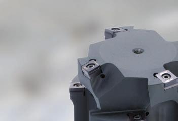
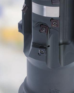
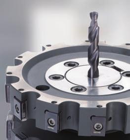
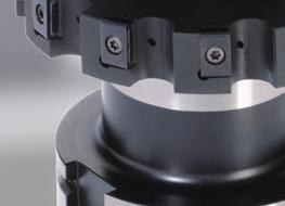
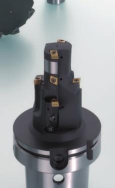
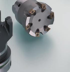
11 Tools with ISO elements Introduction Eight cutting edges on the disc milling cutter LTHU indexable inserts High stability, a soft cut and a large number of cutting edges characterise the MAPAL tangential milling programme. The disc and shoulder milling cutters fitted with the 4+4-cutting edge indexable inserts of type LTHU are a highlight. These peripheral ground indexable inserts combined with the highly accurate MAPAL fixed insert seats in the tool achieve real multi-cutting edge capability during roughing and semi-finishing. On the milling cutters shown below all eight cutting edges can be used in the same machining direction and offer excellent cost-effectiveness. For example: During the milling of the disc slot and the pad seat on a car brake caliper, it was possible to significantly reduce the Cost Per Part (CPP) for the milling process using a disc milling cutter with eight-cutting edge LTHU indexable inserts. Costs per part reduced by 66 % more on the milling cutter range from page 64, more on indexable inserts from page 121 Machine extensively and quickly the MAPAL helix milling cutter For roughing different, in particular large diameters on a workpiece, circular milling is often used. However, a circular milling cutter often requires a large number of cycles until all the machining is complete. This means a low material removal rate and a long machining time. The alternative is the MAPAL helix milling cutter: it superimposes an axial feed movement on the circular movement. With the specially arranged tangential indexable inserts, the tool plunges into the workpiece at full cutting depth. Up to 50 % higher material removal rates secure significant efficiency advantages compared to conventional circular milling. For example: Compared to a porcupine milling cutter, by changing to the MAPAL helix milling cutter it was possible to increase the material removal rate during the machining of a bore with a diameter of 1,300 mm in a GG25 housing from 1,450 to 2,150 cm³/min. Material removal rate increased by 48 % more on helix milling from page

12 12


13 Tools with ISO elements Introduction Index Boring 15 Milling 35 Indexable inserts 67 Innovative 127 complete solutions Cartridges 137 Accessories and spare parts 155 Technical appendix


14 14


15 Tools with ISO elements Boring Boring Introduction Boring tools for pre-machining and fine machining Pre-machining places major challenges on machining manufacture. For this reason a costeffective pre-machining tool is important in the machining process. With a background of fine machining and many years of experience related to bore machining, MAPAL has obtained sound know-how that is manifested in the innovative and very productive boring tools with ISO elements. ISO combination tools tap new productivity potential on a daily basis also in conjunction with other product groups. The tangential roughing and fine boring tools were specially developed for pre-machining and fine machining large diameters; today these tools are available as standard. Programme overview boring 16 Tangential roughing tools TSW 18 Application notes TSW 19 Designation key and series TSW 20 Tangential fine boring tools TFB 26 Application notes TFB 27 Designation key and series TFB 28 Through bore Suitable for open bores. Not suitable for machining shoulders if a 90 angle is required. Blind bore Suitable for closed bores and machining shoulders taking into account the cutting edge length. Internal cooling Tools designed with internal coolant supply. 15


16 Tools with ISO elements Boring Programme overview Boring tools with ISO elements Programme overview 1 2 Standard tools 1 TFB tangential fine boring tool 2 TSW tangential roughing tool The MAPAL tangential roughing tools TSW and tangential fine boring tools TFB are designed as a complete range from the pre-machining to fine machining especially of large bore diameters. 3 Hybrid tools MAPAL hybrid tools combine different machining systems for maximum productivity. Example: combination tool with solid carbide drill and ISO countersink step. 4 Multi-step capability and tangential technology The multi-stage design reduces the tools needed and shortens the machining time. The tangential technology ensures particularly quiet running. In combination with guide pads, the tools achieve very high positioning accuracy. 5 Modular construction of ISO combination tools The modular design of ISO combination tools offers many advantages. For example, entire part families can be machined with fewer tools as only part of the tool needs to be changed. By using connections, for instance a highly accurate HSK-C connection, particularly complex tools can be constructed. Even more machining steps are combined into one tool and the productivity increased even further. 7 Fixed insert seat and cartridge High accuracy manufacturing tolerances on insert seats and indexable inserts guarantee the real multi-cutting edge capability of the ISO tools with fixed insert seats. Cartridges with standard dimensions or in a compact design further increase the flexibility of MAPAL ISO tools. 8 Boring tools with radial technology Depending on the requirements of the part and machining situation, ISO boring tools are also designed with radial indexable inserts External machining tools ISO tools for external machining are individually adapted to the machining task. Whether turning diameters, chamfering or producing special external contours, MAPAL ISO tools are the right solution. The usage of tangential indexable inserts also increases the performance of the tools here


17 Tools with ISO elements Boring Programme overview Exact adjustment Boring Introduction For the cases in which high accuracy indexable inserts and precision milled insert seats are insufficient for the required accuracy, MAPAL uses an adjustment system specially developed for ISO inserts. Here the insert sits on an adjusting wedge with a large contact area. This feature is completely embedded in the tool body and as a result offers the indexable insert a stable seat. The adjusting wedge has an angled surface and can be moved using a lefthand - right-hand threaded adjusting screw. This design produces an indirect, very accurate and easy to use setting feature. As a consequence MAPAL ISO tools achieve accuracies not normally achieved using ISO tools. 4 5 Best machining results due to arc shaped land Due to the normal clearance angle on ISO indexable inserts there is only limited support for the tool during bore machining. Tools then tend to vibration; this vibration effects the surface finish and tool life expectancy. To counteract this problem, MAPAL developed the arc shaped land. This special geometry is a support surface on the cutting edge that supports the tool in the bore and is comparable to an arc land chamfer on fixed reamers. 6 17


18 Tools with ISO elements Boring Tangential roughing tools TSW Tangential roughing tools TSW The MAPAL tangential roughing tools set new standards in relation to stability and performance, particularly in the case of higher stock removal. An innovative, six-cutting edge indexable insert with special support chamfer prevents chatter and vibration. Perfect multi-cutting edge capability with increased stability is ensured by the tangential installation of the indexable inserts in precision insert seats on the front face. Tangential roughing tools Series TSW 101/111 and TSW 201/211 The ground clamping geometry combined with the tangential installation position on the face of the tool body results in a highly positive rake angle and therefore a soft cut and very quiet tool cutting behaviour. This property is further supported by a special support surface on the cutting edges, an arc shaped land, which supports the tool in the bore like an arc land chamfer on reamers. Along with the excellent cutting behaviour of the tangential roughing tools, the necessary drive power required is also reduced, as the machining forces are comparatively low. As a result the tools can also be used on machines with lower torques. It is, however, much more important that, with the same drive power, it is possible to fit more cutting edges to the tools, so that the feeds are increased and machining times drastically reduced. The diameter range of the tools from the standard series is mm, larger diameters are also possible as a custom solution. Two insert sizes available in different substrates cover the entire diameter range. The TSW are available in a monoblock design and as a modular system for larger diameters. The TSW tools are also designed with two different contact angles on the insert seats. The contact angle is 0 on the TSW 101/201 tools for blind bores and 10 on the TSW 111/211 tools for through bores. Features Six-cutting edge tangential indexable insert Soft cutting behaviour Reduced drive power Tool life increased by up to 30 % High cutting depths Six to eight times faster than boring tools 18 The indexable insert has six cutting edges (marked in red) that are used by rotating and turning.


 Z = 4 Tool model for the stated")
19 Tools with ISO elements Boring Tangential roughing tools TSW Application notes TSW monoblock ø mm TSW modular design ø mm Boring TSW / TFB Tool holders Tangential roughing head Length General figures for determining the maximum tool length 350 HSK SK 50 / HSK SK 40 / HSK In case of unfavourable diameter-length ratios a pilot bore is recommended. lmax Diameter Ordering example TSW 111 Pre-machining of a through bore in GGG40 The following are required: Nominal diameter 88.5 mm Depth of the bore mm Material GGG40 Machine spindle HSK-A100 Number of cutting edges (pay attention to machine performance, see page 176) Z = 4 Tool model for the stated machining application: d=88,5 Z=4 TSW111-ø Z A100 (L 2 =55) 5 L 1 =200 L B =138 2 Selected indexable inserts see page 99 WTHQ090608H03L10B041-HP455 19
20 Tools with ISO elements Boring Designation key Designation key for tangential roughing tools TSW Tools: TSW monoblock / TSW roughing heads l h d 1 d 1 TSW 101 and 111 TSW 201 and 211 T S W Ø Z 4 Tool type Tool diameter d 1 and number of teeth TSW TSW TSW TSW Monoblock design TSW 101 = 0 contact angle for blind bores and bores with shoulders TSW 111 = 10 contact angle for through bores Modular design TSW 201 = 0 contact angle for blind bores and bores with shoulders TSW 211 = 10 contact angle for through bores Diameter d 1 No. of teeth Diameter d 1 No. of teeth 37,00-40,40 Z = 2 59,50-74,40 Z = 3 40,50-59,40 Z = 3 74,50-89,40 Z = 4 59,50-74,40 Z = 3 89,50-104,40 Z = 4 74,50-104,40 Z = 4 104,50-119,40 Z = 5 104,50-120,00 Z = 5 119,50-174,40 Z = 5 174,50-280,00 Z = 5 Tool holders: TSW 201 and 211 l h M C A - H S K - A W Type Shank connection Clamping diameter Projection length l h Internal cooling Alignment MCA Arbor HSK-A Custom Hollow shank taper Diameter Nominal length 9 (not Form A of arbor of the arbor specified) 0 HSK-C Hollow shank taper Form C Dimensions in mm. SK Taper shank in acc. with ISO AD/B Without alignment W Length adjustment Without length adjustment 20
21 Tools with ISO elements Boring Designation key A D B 5 0 TSW TSW l k = 40,0 l h l h l k l k d 1 d 1 d 1 d 1 d 1 d 1 Boring TSW / TFB Tool length l 1 = Can be configured as per lengthdiameter diagram Shank form Tool connection TSW monoblock TSW roughing heads TSW Size Code HSK-C 63 C63 HSK-C 80 C80 HSK-C 100 C100 HSK-A 63 A63 HSK-A 80 A80 HSK-A 100 A100 SK-AD/B 40 ADB40 SK-AD/B 50 ADB50 TSW Connection Connection ø-range Clamping diameter Code 59,50-74,40 ø 18 D18 74,50-89,40 ø 22 D22 Mounting bore 89,50-119,40 ø 27 D27 119,50-174,40 ø 40 D40 174,50-280,00 ø 60 D60 21
22 Tools with ISO elements Boring Tangential roughing tools TSW 101 tangential roughing tools Monoblock design Contact angle 0 For blind bores and bores with shoulders l 2 l 1 d 1 Machine connection HSK d 1 Number Nominal Tool lengths Indexable insert TORX screw of cutting size edges HSK l2 l1 min l1 max 37,00-40, ,50-59, ,50-74, ,50-104, ,50-120,00 5 HSK-A HSK-C HSK-A HSK-C HSK-A HSK-C l 2 l 1 See diagram Page 19 See diagram Page 19 WTHQ 0705 L00BO26 WTHQ 0906 L00BO41 Page 98 Page 98 TX15-M4x TX20-M5x d 1 Machine connection ISO d 1 Number Nominal Tool lengths Indexable insert TORX screw of cutting size edges ISO l2 l1 min l1 max ISO-AD / ISO-B ISO-AD / ISO-B ISO-AD / ISO-B 37,00-40, ,50-59, ,50-74, ,50-104, ,50-120,00 5 Further dimensions and lengths on request. Dimensions in mm See diagram Page 19 See diagram Page 19 WTHQ 0705 L00BO26 WTHQ 0906 L00BO41 TX15-M4x TX20-M5x Please note: If the collar diameter at l 2 is smaller than d 1, it is also to be taken into account in the machining length. Page 98 Page 98
23 Tools with ISO elements Boring Tangential roughing tools TSW 111 tangential roughing tools Monoblock design Contact angle 10 For through bores l 2 l 1 Boring TSW / TFB d 1 10 Machine connection HSK d 1 Number Nominal Tool lengths Indexable insert TORX screw of cutting size edges HSK l2 l1 min l1 max 37,00-40, ,50-59, ,50-74, ,50-104, ,50-120,00 5 HSK-A HSK-C HSK-A HSK-C HSK-A HSK-C l 2 See diagram Page 19 See diagram Page 19 l 1 WTHQ 0705 L10BO26 WTHQ 0906 L10BO41 Page 99 Page 99 TX15-M4x TX20-M5x d 1 Machine connection ISO 10 d 1 Number Nominal Tool lengths Indexable insert TORX screw of cutting size edges ISO l2 l1 min l1 max ISO-AD / ISO-B ISO-AD / ISO-B ISO-AD / ISO-B 37,00-40, ,50-59, ,50-74, ,50-104, ,50-120,00 5 Further dimensions and lengths on request. Dimensions in mm See diagram Page 19 See diagram Page 19 WTHQ 0705 L10BO26 WTHQ 0906 L10BO41 TX15-M4x TX20-M5x Please note: If the collar diameter at l 2 is smaller than d 1, it is also to be taken into account in the machining length. Page 99 Page 99 23
24 Tools with ISO elements Boring Tangential roughing heads TSW 201 tangential roughing heads Modular design Contact angle 0 For blind bores and bores with shoulders l k d 2 d 3 d 1 d 1 Number of cutting d 3 l k d 2 edges Indexable insert TORX screw 59,50-74, ,50-89, ,50-104, ,50-119, ,50-174, ,50-280, TSW 211 tangential roughing heads Modular design Contact angle 10 For through bores d 1 Number of cutting d 3 l k d 2 edges 59,50-74, ,50-89, ,50-104, ,50-119, ,50-174, ,50-280, d 2 d 3 l k 10 d 1 WTHQ 0906 L00B041 WTHQ 0906 L00B081 Indexable insert WTHQ 0906 L10B041 WTHQ 0906 L10B081 Page 99 Page 99 Page 99 Page TORX screw Further dimensions and lengths on request. Dimensions in mm. 24
25 Tools with ISO elements Boring Tool holders for tangential roughing heads TH-TSW 201 and 211 tool holders for tangential roughing heads l h l 2 d 3 d 2 Boring TSW / TFB Machine connection HSK (DIN ) For tool ø d 3 d 2 Nominal size Tool holder lengths HSK l2 lh min lh max HSK-A HSK-C HSK-A HSK-C HSK-A HSK-C ,50-74, ,50-89, ,50-119, ,50-174, ,50-280, l 2 l h d 3 d 2 Machine connection ISO (DIN Form AD / B) For tool ø d 3 d 2 59,50-74, ,50-89, ,50-119, ,50-174, ,50-280, Further dimensions and lengths on request. Dimensions in mm. Nominal size ISO Tool holder lengths l 2 l h min l h max ISO-AD / ISO-B ISO-AD / ISO-B ISO-AD / ISO-B


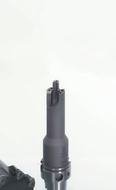
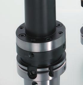
26 Tools with ISO elements Boring Tangential fine boring tools TFB Tangential fine boring tools TFB Tangential technology now also for fine machining. Newly developed reaming cutting edges are mounted in precision insert seats and set sensitively and highly accurately to a defined amount above the reference setting pads using the MAPAL wedge adjustment. Up to IT 7 The tool is guided in the bore by the special arc shaped land. The MAPAL TFB series impresses due to easy, precise handling, quiet running at high feeds and the best machining results. Tangential fine boring tools Series TFB 101/111 The tangential fine boring tools are far superior to the previous conventional tool systems for the fine machining of large diameters. Compared to one or two-cutting edge boring tools the TFB tools are six to eight times faster with machining results in reaming quality. During fine machining the effect of the arc shaped land is even more significant than on the roughing tools it guides the tool in the bore and at the same time smoothes the surface. The TFB tools are equipped with six to eight indexable inserts that are embedded in the tool body unevenly in relation to each other. The reaming cutting edges are mounted in precision insert seats; a MAPAL wedge adjustment feature for exact and very sensitive adjustment is fitted for each cutting edge. Precision ground reference pads are used as a setting aid. The setting of the tools is enormously simplified, as the cutting edge only needs to be set to a specific amount beyond the pad diameter, a task that is very easy using commonly available measuring equipment and the sensitive adjustment accurate to the μm (see setting instructions on page 180). The TFB tangential fine boring tools comprise of three assemblies. The machine adapter and the intermediate adapter are connected via a MAPAL Module connection with radial and axial alignment, as a result the radial run-out error on the spindle can be compensated. The tangential fine boring head is connected to the intermediate adapter via an HSK connection. The standard diameter range is from ø 60 to 280 mm. The TFB tools are available in two different series. TFB 101 for blind bores and TFB 111 for through bores. Features MAPAL arc shaped land guides the tool and smoothes the bore Highly positive rake angle for soft cut High precision insert seats Bores in reaming quality Six to eight times faster than boring tools Straightforward, sensitive adjustment 26
 For a specific requirement on the positioning accuracy General figures")

27 Tools with ISO elements Boring Tangential fine boring tools TFB Application notes TFB modular design ø mm Machine adapter Intermediate adapter Tangential fine boring head Standard lead geometries 1 30 For improved MG surface finish Boring TSW / TFB 0,55 MC 0,4 MA Without any specific requirement (standard) For a specific requirement on the positioning accuracy General figures for determining the maximum tool length Length HSK 100 SK 50 / HSK 80 SK 40 / HSK 63 In case of unfavourable diameter-length ratios a pilot bore is recommended. lmax1 lmax Diameter Ordering example TFB 111 Fine machining of a through bore in GGG40 4 L B =138 2 The following are required: Nominal diameter 89,0 mm Tolerance ( < IT7) H7 (+0.035/0) Depth of the bore mm Material GGG40 Machine spindle HSK-A100 Number of cutting edges (pay attention to machine performance) Z = 6 Tool for the stated machining application: d 1 =89 H7 OS-AD-HSK-A100-MOD KS-VL-MOD100-HSK-C TFB111-ø Z C63 L Ma =65 L Za =100 L k =65 L 1 =230 Selected for indexable inserts see page 96 FTHW0905MCD01L00B030-CP131 27
28 Tools with ISO elements Boring Designation key Designation key for tangential fine boring tools TFB Tool: TFB fine boring heads l k d 1 d 1 TFB 101 and 111 T F B Ø Z 8 Tool type Tool diameter d 1 and number of teeth TFB TFB Modular design TFB 101 = Blind bores and bores with shoulders TFB 111 = Through bores Diameter d 1 No. of teeth 60,00-74,99 Z = 6 75,00-89,99 Z = 6 90,00-109,99 Z = 8 110,00-119,99 Z = 8 120,00-159,99 Z = 8 160,00-179,99 Z = 8 180,00-280,00 Z = 8 Machine adapter: TFB 101 and 111 l MA l ZA O S - A D - H S K - A M O D Type Adaptation Shank Form and size Adaptation Form and size Projection length L MA Alignment Internal cooling OS Without clamping unit Dimensions in mm. AD Adapters HSK-A HSK-C SK Hollow shank taper Form A Hollow shank taper Form C Taper shank in acc. with ISO AD/B MOD Module connection Nominal length of the machine adapter 0 Without alignment 1 2 Radial alignment Radial and angular alignment 1 Internal 28
29 Tools with ISO elements Boring Designation key Boring TSW / TFB C Tool length Shank form Tool diameter Tool length Connection Size Code 60,00-74,99 65,0 75,00-89,99 65,0 90,00-109,99 65,0 110,00-119,99 75,0 120,00-159,99 75,0 160,00-179,99 95,0 180,00-280,00 95,0 HSK-C 50 C50 HSK-C 63 C63 HSK-C 80 C80 HSK-C 100 C100 Intermediate adapter: TFB 101 and 111 l ZA K S - V L - M O D H S K - C Clamping unit Adaptation Shank Form and size Adaptation Form and size Projection length l ZA Alignment Internal cooling KS KS clamping cartridge VL Flange adapter MOD Module connection HSK-C Hollow Nominal length shank taper of the adapter Form C 0 1 Without alignment Radial alignment 1 Internal 2 Radial and angular alignment 29
30 Tools with ISO elements Boring Tangential fine boring heads TFB 101 tangential fine boring heads Modular design l k d 1 d 1 Number of cutting edges Number of setting pads Nominal size HSK l k Indexable insert TORX PLUS screw 60,00-74, HSK-C ,00-89, HSK-C ,00-109, HSK-C63 65 FTHW 0905 BO30 Page 96 TX-M3,5x ,00-119, HSK-C ,00-159, HSK-C ,00-179, HSK-C FTHW 0905 BO60 Page 96 TX-M3,5x ,00-280, HSK-C FTHW 0905 BO90 Page 96 TX-M3,5x Further dimensions and lengths on request. Dimensions in mm. 30
31 Tools with ISO elements Boring Tangential fine boring heads TFB 111 tangential fine boring heads Modular design l k d 1 Boring TSW / TFB d 1 Number of cutting edges Number of setting pads Nominal size HSK l k Indexable insert TORX PLUS screw 60,00-74, HSK-C ,00-89, HSK-C ,00-109, HSK-C63 65 FTHW 0905 BO30 Page 96 TX-M3,5x ,00-119, HSK-C ,00-159, HSK-C ,00-179, HSK-C FTHW 0905 BO60 Page 96 TX-M3,5x ,00-280, HSK-C FTHW 0905 BO90 Page 96 TX-M3,5x Further dimensions and lengths on request. Dimensions in mm. 31
32 Tools with ISO elements Boring Intermediate adapters Intermediate adapter D d 1 l 2 l ZA With radial and angular alignment For tool ø Module diameter Nominal size HSK Dimensions Weight Specification D HSK d 1 l ZA l 2 kg 60,00-74, ,00-109, ,00-159, ,00-280, ,9 KS-VL-MOD080-HSK-C ,9 KS-VL-MOD080-HSK-C ,65 KS-VL-MOD080-HSK-C ,4 KS-VL-MOD080-HSK-C ,8 KS-VL-MOD100-HSK-C ,2 KS-VL-MOD100-HSK-C ,8 KS-VL-MOD100-HSK-C ,6 KS-VL-MOD100-HSK-C ,7 KS-VL-MOD117-HSK-C ,7 KS-VL-MOD117-HSK-C ,65 KS-VL-MOD117-HSK-C ,6 KS-VL-MOD117-HSK-C ,9 KS-VL-MOD140-HSK-C ,6 KS-VL-MOD140-HSK-C ,6 KS-VL-MOD140-HSK-C Supply includes: Standard KS clamping cartridge, thrust pad and threaded pin, stop ring and cylinder head screws (for fastening the KS flange adapter). Dimensions in mm. For spare parts for intermediate adapters see page
33 Tools with ISO elements Boring Machine adapters Machine adapter G 1 G D Boring TSW / TFB l MA For tool ø Locating shank Module diameter Dimensions Weight Specification D l MA G G 1 kg 60,00-74,99 75,00-109,99 110,00-159,99 160,00-280,00 HSK-A SK BT CAT HSK-A SK BT CAT HSK-A SK BT CAT HSK-A SK BT CAT M6 M8x1 1,4 OS-AD-HSK-A063-MOD M6 M8x1 2,1 OS-AD-HSK-A080-MOD M6 M8x1 3 OS-AD-HSK-A100-MOD AD/B M6 M8x1 1,7 OS-AD-SK040-MOD AD/B M6 M8x1 3,6 OS-AD-SK050-MOD M6 M8x1 2 OS-AD-BT040-MOD M6 M8x1 5,1 OS-AD-BT050-MOD M6 M8x1 1,7 OS-AD-CAT040-MOD M6 M8x1 3,6 OS-AD-CAT050-MOD M8 M10x1 2,1 OS-AD-HSK-A063-MOD M8 M10x1 2,6 OS-AD-HSK-A080-MOD M8 M10x1 3,7 OS-AD-HSK-A100-MOD AD/B M8 M10x1 2,2 OS-AD-SK040-MOD AD/B M8 M10x1 4,4 OS-AD-SK050-MOD M8 M10x1 2,6 OS-AD-BT040-MOD M8 M10x1 5,3 OS-AD-BT050-MOD M8 M10x1 2,2 OS-AD-CAT040-MOD M8 M10x1 4,4 OS-AD-CAT050-MOD M8 M10x1 2,5 OS-AD-HSK-A063-MOD M8 M10x1 3,1 OS-AD-HSK-A080-MOD M8 M10x1 4 OS-AD-HSK-A100-MOD AD/B AD/B M8 M10x1 4,5 OS-AD-SK050-MOD M8 M10x1 6,3 OS-AD-BT050-MOD M8 M10x1 4,5 OS-AD-CAT050-MOD M10 M10x1 4,2 OS-AD-HSK-A080-MOD M10 M10x1 5,2 OS-AD-HSK-A100-MOD AD/B AD/B M10 M10x1 4,7 OS-AD-SK050-MOD M8 M10x1 6,6 OS-AD-BT050-MOD M8 M10x1 4,7 OS-AD-CAT050-MOD Supply includes: Complete with threaded pins for aligning the radial run-out, does not include coolant tube. Dimensions in mm. For spare parts for machine adapters see page
34 34

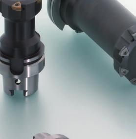
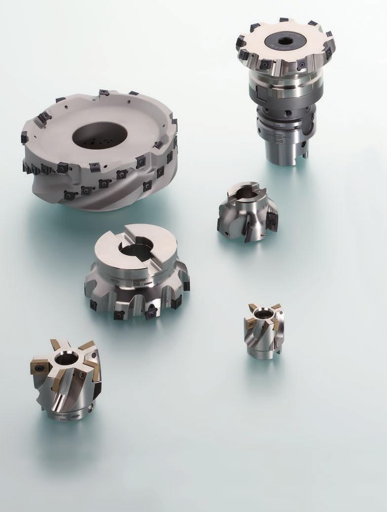
35 Tools with ISO elements Milling Milling Introduction MAPAL PerformanceMill ISO milling cutters MAPALs experience in the area of high performance custom ISO tools has been implemented in a standard programme of radial and tangential tools for a very wide range of applications. The PerformanceMill milling cutters are designed with high accuracy insert seats and include, along with face and shoulder cutter heads, also shell end face and disc milling cutters as well as the particularly innovative helix milling cutters for end face and bore machining. Perfectly matched cutting edge geometries and high performance coatings are basic features of the milling cutter indexable inserts. Programme overview milling 36 Designation key 38 Face milling cutters 40 Shoulder milling cutters 43 Shell end face milling cutters 51 Helix milling cutters 56 Disc milling cutters 59 Custom milling cutters 65 Trimming / edge milling Shoulder milling Disc milling cutters Shoulder milling deep Face milling Shoulder milling Gang milling cutters Shoulder milling (face circumferential milling) Groove milling Plunge milling linear Helix milling Internal cooling Tools are designed with internal coolant supply. Shank form Shank form 35
 Tool ø (mm) Indexable insert 7 7 63-160 63-160 CT_D... / CT_Q CT_D.")
36 Tools with ISO elements Milling Programme overview Programme overview milling Milling cutter type Face milling cutters IFM75-C2/C4 Shoulder milling cutters ICM90-C2/C4 Wide pitch Close pitch Number of cutting edges 2 or 4 2 or 4 Application Cutting depth a p max. (mm) Tool ø (mm) Indexable insert CT_D... / CT_Q CT_D... / CT_Q P M K N S Roughing Medium machining Finishing Page / 46 Milling cutter type ISM90-B2-Shank Shell end face milling cutters ISM90-B2 ISM90-C2/C4-HSK/ISO Number of cutting edges or 4 Application Cutting depth a p max. (mm) Tool ø (mm) Indexable insert 37 / / BD_T.. BD_T.. CT_D... / CT_Q P M K N S Roughing Medium machining Finishing Page highly suitable suitable in some situations not suitable

37 Tools with ISO elements Milling Programme overview Shoulder milling cutters ICM90-C2/C4-Finishing ICM90-S4 ICM90-B2-Shank ICM90-B2 Milling Introduction 2 or / 13 8 / CT_H... / CT_A SE_T BD_T.. BD_T.. 45 / Helix milling cutters Disc milling cutters IHM90-C2/C4-HSK IHM90-C2/C4 IDM90-C2/C4 IDM88-L8 2 or 4 2 or 4 2 or / CT_D... / CT_Q CT_D... / CT_Q CT_D... / CT_Q LT_U
38 Tools with ISO elements Milling Designation key Designation key milling cutter programme I F M C A Milling cutter type Internal cooling Tool diameter Connection (Examples) IFM Face milling cutters 0 Without IC 125 Milling cutter ø = 125 mm HA32 Cylindrical shank HA ø = 32 mm 1 With IC HB32 Cylindrical shank HB ø = 32 mm ICM Shoulder milling cutters HE32 Cylindrical shank HE ø = 32 mm ISM Shell end face milling cutters CA16 CA22 Milling cutter arbor ø = 16 mm Milling cutter arbor ø = 22 mm IHM Helix milling cutters CA27 Milling cutter arbor ø = 27 mm IDM Disc milling cutters CA32 Milling cutter arbor ø = 32 mm CA40 Milling cutter arbor ø = 40 mm CA60 Milling cutter arbor ø = 60 mm Contact angle / insert installation position A063 A080 A100 C063 C100 HSK-A63 HSK-A80 HSK-A100 HSK-C63 HSK-C100 T063 HSK-T63 S050 ISO50 S040 ISO40 38
39 Tools with ISO elements Milling Designation key Z 1 0 R - C T _ D M Milling Introduction Effective number of cutting edges (eff.) (Examples) Direction of rotation Indexable insert Z5 Z10 Z9+3 Eff. number of teeth = 5 Eff. number of teeth = 10 Eff. number of teeth = 12 of which 3 adjustable cutting edges R L R1 Right Left Right / milling cutter (left-side cutting) 2. digit "T" 2. digit "E, D" CT... Tangential LT... Tangential BD... Radial SE... Radial Z12+4 Eff. number of teeth = 16 of which 4 adjustable cutting edges R2 Right / milling cutter (right-side cutting) Optional Z6+6 Disc milling cutters Eff. number of teeth = 6 (both sides, 3-sided cutting) R3 Right / milling cutter (both sides, 3-sided cutting) Modified body material / Type M 39

40 Tools with ISO elements Milling Face milling cutters Face milling cutter IFM Face milling cutter 75 Tangential IFM75-C2 IFM75-C4 Properties - Internal coolant supply - Enlarged face connection - Fixed insert seats - Wide, middle and narrow pitch - 75 contact therefore lower radial forces Application notes - For roughing and semi-machining - Large chip spaces for high chip volume Two-cutting edge indexable insert CT_D09T3 Four-cutting edge indexable insert CT_Q0905 Preferred for aluminium also PCD-tipped. Preferred for castings and steel. For castings also PcBN-tipped. 40
41 Tools with ISO elements Milling Face milling cutters Face cutter head with tangential technology IFM75-C2 κ 75 l 1 a p κ d 2 d 3 d 4 d 1 Face milling cutters CT_D09T3 / wide pitch Dimensions a p max. Weight kg Max. spindle speed (min -1 ) Specification ø d 1 Z e ff ø d 2 l 1 ø d 3 ø d , IFM CA22-Z4R-CT_D , IFM CA27-Z5R-CT_D , IFM CA32-Z6R-CT_D , IFM CA40-Z7R-CT_D , IFM CA40-Z8R-CT_D , IFM CA60-Z12R-CT_D CT_D09T3 / middle pitch , IFM CA22-Z6R-CT_D , IFM CA27-Z7R-CT_D , IFM CA32-Z9R-CT_D , IFM CA40-Z10R-CT_D , IFM CA40-Z12R-CT_D , IFM CA60-Z16R-CT_D CT_D09T3 / narrow pitch , IFM CA22-Z8R-CT_D , IFM CA27-Z12R-CT_D , IFM CA32-Z14R-CT_D , IFM CA40-Z18R-CT_D , IFM CA40-Z20R-CT_D , IFM CA60-Z25R-CT_D Accessories Spare parts* CT_D09T3 Indexable insert Page CT_D09T3 Clamping screw for indexable insert TORX PLUS M3.5x9.4-TX10-IP Clamping systems / adapters See section Accessories Page 162 CT_D09T3 TORX PLUS screwdriver with handle 10IPx80x Milling cutter clamping screws See section Accessories Page 158 * Supply includes. Dimensions in mm. 41
42 d 1 d 2 d 3 Tools with ISO elements Milling Face milling cutters Face cutter head with tangential technology IFM75-C4 κ 75 l 1 a p κ d 4 CT_Q0905 / wide pitch Dimensions a p max. Weight kg Max. spindle speed (min -1 ) Specification ø d 1 Z e ff ø d 2 l 1 ø d 3 ø d , IFM CA22-Z4R-CT_Q , IFM CA27-Z5R-CT_Q , IFM CA32-Z6R-CT_Q , IFM CA40-Z7R-CT_Q , IFM CA40-Z8R-CT_Q IFM CA60-Z12R-CT_Q CT_Q0905 / middle pitch , IFM CA22-Z6R-CT_Q , IFM CA27-Z7R-CT_Q , IFM CA32-Z9R-CT_Q , IFM CA40-Z10R-CT_Q , IFM CA40-Z12R-CT_Q IFM CA60-Z16R-CT_Q CT_Q0905 / narrow pitch , IFM CA22-Z8R-CT_Q , IFM CA27-Z12R-CT_Q , IFM CA32-Z14R-CT_Q , IFM CA40-Z18R-CT_Q , IFM CA40-Z20R-CT_Q , IFM CA60-Z25R-CT_Q Accessories Spare parts* CT_Q0905 Indexable insert Page 119 CT_Q0905 Clamping screw for indexable insert TORX PLUS M3.5x11-TX10-IP Clamping systems / adapters See section Accessories Page 162 CT_Q0905 TORX PLUS screwdriver with handle 10IPx80x Milling cutter clamping screws See section Accessories Page 158 * Supply includes. Dimensions in mm. 42

43 Tools with ISO elements Milling Shoulder milling cutters Shoulder milling cutter ICM Shoulder milling cutter 90 Tangential Radial ICM90-C2/C4 ICM90-C2/C4 Finishing ICM90-S4 ICM90-B2- Shank Shoulder milling cutters ICM90-B2 Properties - Internal coolant supply - Enlarged face connection - Fixed insert seats - Wide, middle and narrow pitch - Internal coolant supply - Enlarged face connection - Adjustable finishing indexable insert - Close pitch - Internal coolant supply - Fixed insert seats - Positive installation position of the indexable insert for short projection length - Internal coolant supply - Fixed insert seats Application notes - For roughing and semi-finish machining - 90 shoulder surfaces possible - For roughing and semi-finish machining - 90 shoulder surfaces possible Adjustable finishing indexable insert - For roughing and semi-finish machining - 90 shoulder surfaces possible Preferred for castings and steel. - For roughing and semi-finish machining - 90 shoulder surfaces possible - Ramping milling is possible to a limited extent (up ø 63) - Plunging possible Preferred for castings and steel. Initial value for adjustable finishing indexable inserts 0.02 mm 0.04 mm. Two-cutting edge indexable insert Four-cutting edge indexable insert CT_D09T3 CT_Q0905 Preferred for aluminium also PCD-tipped. Preferred for castings and steel. For castings also PcBN-tipped. 43
44 a p κ d 1 d 2 d 3 Tools with ISO elements Milling Shoulder milling cutters Shoulder cutter head with tangential technology ICM90-C2 κ 90 l 1 d 4 CT_D09T3 / wide pitch Dimensions a p max. Weight kg Max. spindle speed (min -1 ) Specification ø d 1 Z e ff ø d 2 l 1 ø d 3 ø d , ICM CA22-Z4R-CT_D ICM CA27-Z5R-CT_D , ICM CA32-Z6R-CT_D , ICM CA40-Z7R-CT_D ICM CA40-Z8R-CT_D , ICM CA60-Z12R-CT_D CT_Q09T3 / middle pitch , ICM CA22-Z6R-CT_D , ICM CA27-Z7R-CT_D , ICM CA32-Z9R-CT_D , ICM CA40-Z10R-CT_D , ICM CA40-Z12R-CT_D , ICM CA60-Z16R-CT_D CT_Q09T3 / narrow pitch , ICM CA22-Z8R-CT_D , ICM CA27-Z12R-CT_D , ICM CA32-Z14R-CT_D , ICM CA40-Z18R-CT_D , ICM CA40-Z20R-CT_D , ICM CA60-Z25R-CT_D Accessories Spare parts* CT_D09T3... Indexable insert Page CT_D09T3... Clamping screw for indexable insert TORX PLUS M3.5x9.4-TX10-IP Clamping systems / adapters See section Accessories Page 162 CT_D09T3... TORX PLUS screwdriver with handle 10IPx80x Milling cutter clamping screws See section Accessories Page 158 * Supply includes. Dimensions in mm. 44
 Specification Shoulder milling cutters ø d 1 Z e ff ø d 2 l 1 ø d 3 ø d 4 63 6 (4+2) 22 50 48 28 0.4 / 3.0 0,5 10.")
45 Tools with ISO elements Milling Shoulder milling cutters Shoulder cutter head with tangential technology ICM90-C2-Finishing κ 90 l 1 a p κ d 2 d 3 d 4 d 1 CT_D09T3 Dimensions a p max. Weight kg Max. spindle speed (min -1 ) Specification Shoulder milling cutters ø d 1 Z e ff ø d 2 l 1 ø d 3 ø d (4+2) / 3.0 0, ICM CA22-Z4+2R-CT_D (6+2) / 3.0 0, ICM CA27-Z6+2R-CT_D (8+2) / 3.0 1, ICM CA32-Z8+2R-CT_D (9+3) / 3.0 2, ICM CA40-Z9+3R-CT_D (12+4) / 3.0 4, ICM CA40-Z12+4R-CT_D (15+5) / 3.0 8, ICM CA60-Z15+5R-CT_D Accessories Selection notes CT_D09T3... Indexable insert Page CT_A09T3 Indexable insert Page 118 Clamping systems / adapters See section Accessories Page 162 a p max. 0.4 mm on assembly with CT_D09T3 and CT_A09T3 a p max. 3.0 mm on assembly entirely with CT_D09T3 Milling cutter clamping screws See section Accessories Page 158 Spare parts* CT_D09T3... CT_A09T3... Clamping screw for indexable insert TORX PLUS M3.5x9.4-TX10-IP Assembly note: Assembly example ø 100, Z e ff 10(8+2) CT_D09T3... CT_A09T3... TORX PLUS screwdriver with handle 10IPx80x191 Adjusting wedge M4x0.5 Threaded spindle M4x0.5 LH/RHx9 with screw locking K K On assembly with wide face indexable inserts (CT_A09T3), 8 pieces CT_D09T3 and 2 pieces CT_A09T3 are fitted. Here the wide face indexable inserts (CT_A09T3) are fitted in the insert seats with axial adjustment. On assembly without wide face indexable inserts, 10 pieces CT_D09T3 are fitted. For setting instructions see page 195. Hex wrench Wrench size (sw) * Supply includes. Dimensions in mm. 45
 Specification ø d 1 Z e ff ø d 2 l 1 ø d 3 ø d 4 63 4 22 50 48 28 7 0,6 8.000 ICM901-063-CA22-Z4R-CT_Q09 30395509 80 5 27 50 60 38 7 0,8 6.")
46 Tools with ISO elements Milling Shoulder milling cutters Shoulder cutter head with tangential technology ICM90-C4 κ 90 l 1 a p κ d 2 d 3 d 4 d 1 CT_Q0905 / wide pitch Dimensions a p max. Weight kg Max. spindle speed (min -1 ) Specification ø d 1 Z e ff ø d 2 l 1 ø d 3 ø d , ICM CA22-Z4R-CT_Q , ICM CA27-Z5R-CT_Q , ICM CA32-Z6R-CT_Q , ICM CA40-Z7R-CT_Q , ICM CA40-Z8R-CT_Q , ICM CA60-Z12R-CT_Q CT_Q0905 / middle pitch , ICM CA22-Z6R-CT_Q , ICM CA27-Z7R-CT_Q , ICM CA32-Z9R-CT_Q , ICM CA40-Z10R-CT_Q , ICM CA40-Z12R-CT_Q , ICM CA60-Z16R-CT_Q CT_Q0905 / narrow pitch , ICM CA22-Z8R-CT_Q , ICM CA27-Z12R-CT_Q , ICM CA32-Z14R-CT_Q , ICM CA40-Z18R-CT_Q , ICM CA40-Z20R-CT_Q , ICM CA60-Z25R-CT_Q Accessories Spare parts* CT_Q0905 Indexable insert Page 119 CT_Q0905 Clamping screw for indexable insert TORX PLUS M3.5x11-TX10-IP Clamping systems / adapters See section Accessories Page 162 CT_Q0905 TORX PLUS screwdriver with handle 10IPx80x Milling cutter clamping screws See section Accessories Page 158 * Supply includes. Dimensions in mm. 46
47 Tools with ISO elements Milling Shoulder milling cutters Shoulder cutter head with tangential technology ICM90-C4-Finishing κ 90 l 1 a p κ d 2 d 3 d 4 d 1 CT_Q0905 Dimensions a p max. Weight kg Max. spindle speed (min -1 ) Specification Shoulder milling cutters ø d 1 Z e ff ø d 2 l 1 ø d 3 ø d (4+2) / 3.0 0, ICM CA22-Z4+2R-CT_Q (6+2) / 3.0 0, ICM CA27-Z6+2R-CT_Q (8+2) / 3.0 1, ICM CA32-Z8+2R-CT_Q (9+3) / 3.0 2, ICM CA40-Z9+3R-CT_Q (12+4) / 3.0 4, ICM CA40-Z12+4R-CT_Q (15+5) / 3.0 8, ICM CA60-Z15+5R-CT_Q Accessories Selection notes CT_Q Indexable insert Page 119 CT_H0905 Indexable insert Page 120 Clamping systems / adapters See section Accessories Page 162 a p max. 0.4 mm on assembly with CT_Q0905 and CT_H0905 a p max. 3.0 mm on assembly entirely with CT_Q0905 Milling cutter clamping screws See section Accessories Page 158 Spare parts* CT_Q0905 CT_H0905 Clamping screw for indexable insert TORX PLUS M3.5x11-TX10-IP Assembly note: Assembly example ø 160, Z e ff 16 (12+4) CT_Q0905 CT_H0905 TORX PLUS screwdriver with handle 10IPx80x191 Adjusting wedge M4x0.5 Threaded spindle M4x0.5 LH/RHx9 with screw locking K K On assembly with wide face indexable inserts (CT_H0905) 12 pieces CT_Q0905 and 4 pieces CT_H0905 are fitted. Here the wide face indexable inserts (CT_H0905) are fitted in the insert seats with axial adjustment. On assembly without wide face indexable inserts, 16 pieces CT_Q0905 are fitted. For setting instructions see page 195. Hex wrench Wrench size (sw) * Supply includes. Dimensions in mm. 47
48 Tools with ISO elements Milling Shoulder milling cutters Shoulder cutter head with radial technology ICM90-S4 κ 90 l1 ap κ d2 d3 d4 d1 SE_T09T3 Dimensions a p max. Weight kg Max. spindle speed (min -1 ) Specification ø d 1 Z e ff ø d 2 l 1 ø d 3 ø d ,5 7 0, ICM CA16-Z4R-SE_T ,5 7 0, ICM CA22-Z5R-SE_T ,5 7 0, ICM CA22-Z6R-SE_T , ICM CA27-Z7R-SE_T , ICM CA32-Z9R-SE_T SE_T1504 Dimensions a p max. Weight kg Max. spindle speed (min -1 ) Specification ø d 1 Z e ff ø d 2 l 1 ø d 3 ø d ,5 13 0, ICM CA22-Z5R-SE_T , ICM CA27-Z6R-SE_T , ICM CA32-Z6R-SE_T , ICM CA40-Z7R-SE_T , ICM CA40-Z9R-SE_T , ICM CA60-Z11R-SE_T Accessories Spare parts* SE_T09 SE_T15 Indexable insert Page 124 SE_T09T3 Clamping screw for indexable insert TORX PLUS M3x8.5-TX8-IP Clamping systems / adapters See section Accessories Page 162 SE_T09T3 TORX PLUS screwdriver with handle 10IPx80x Milling cutter clamping screws* Page 158 SE_T1504 Clamping screw for indexable insert TORX PLUS M5x11-TX20-IP SE_T1504 TORX PLUS screwdriver with handle 20IPx100x * Supply includes. Dimensions in mm. 48
49 Tools with ISO elements Milling Shoulder milling cutters End milling cutter with radial technology ICM90-B2-Shank κ 90 B2 l 1 l 2 a p κ d 2 d 1 BD_T11T3 Dimensions ø d 1 Z e ff ø d 2 l 1 l 2 a p max. Weight kg Max. Spindle speed (min -1 ) Cylindrical shank form Specification Type M** (modified) (standard) Shoulder milling cutters , HA ICM HA16-Z2R-BD_T , HB ICM HB16-Z2R-BD_T , HA ICM HA20-Z3R-BD_T , HB ICM HB20-Z3R-BD_T , HA ICM HA25-Z3R-BD_T , HB ICM HB25-Z3R-BD_T , HA ICM HA32-Z4R-BD_T , HB ICM HB32-Z4R-BD_T HA ICM HA32-Z5R-BD_T , HB ICM HB32-Z5R-BD_T BD_T , HA ICM HA25-Z2R-BD_T , HB ICM HB25-Z2R-BD_T , HA ICM HA32-Z3R-BD_T , HB ICM HB32-Z3R-BD_T HA ICM HA32-Z4R-BD_T , HB ICM HB32-Z4R-BD_T Accessories Spare parts* BD_T11T3 BD_T1704 Indexable insert** Page BD_T11T3 Clamping screw for indexable insert TORX M2.5x5.4-TX See catalogue "MAPAL competence clamping technology" BD_T11T3 TORX screwdriver with handle TX8x60x BD_T1704 Clamping screw for indexable insert TORX M4x6.9-TX BD_T1704 TORX screwdriver with handle TX15x80x * Supply includes. ** On assembly with indexable inserts with a radius >1.2 mm, the modified milling cutter type M must be selected. Alternatively the standard milling cutter can be ordered and re-worked by the customer. Information on this aspect is given in the Technical appendix on page 193. Dimensions in mm. 49
50 Tools with ISO elements Milling Shoulder milling cutters Shoulder cutter head with radial technology ICM90-B2 κ 90 l1 ap κ d3 d2 d4 d1 BD_T1704 Dimensions ø d 1 Z e ff ø d 2 l 1 ø d 3 ø d 4 a p max. Weight kg Max. spindle speed (min -1 ) Specification Type M** (modified) (standard) , ICM CA16-Z4R-BD_T , ICM CA22-Z4R-BD_T , ICM CA22-Z5R-BD_T , ICM CA27-Z6R-BD_T , ICM CA32-Z7R-BD_T Accessories Spare parts* BD_T1704 Indexable insert** Page BD_T1704 Clamping screw for indexable insert TORX M4x6.9-TX Clamping systems / adapters See section Accessories Page 162 BD_T1704 TORX screwdriver with handle TX15x80x Milling cutter clamping screws See section Accessories Page 158 * Supply includes. ** On assembly with indexable inserts with a radius >1.2 mm, the modified milling cutter type M must be selected. Alternatively the standard milling cutter can be ordered and re-worked by the customer. Information on this aspect is given in the Technical appendix on page 193. Dimensions in mm. 50
51 Tools with ISO elements Milling Shell end face milling cutters Shell end face milling cutters ISM Shell end face milling cutters 90 Radial Tangential ISM90-B2-Shank ISM90-B2 ISM90-C2/C4-HSK ISM90-C2/C4-SK Shell end face milling cutters Properties - Internal coolant supply - Fixed insert seats - Without internal coolant supply - Internal coolant supply - Fixed insert seats Application notes - For roughing - Ideal for heavy machining, flute milling, trimming, shoulder milling - For high chip volume - For roughing - For deep shoulder milling and trimming - For large cutting depths (ap) Preferred for steel and aluminium, to a limited extent for castings. Assembly note The carrier tool is fitted with the same number of indexable inserts of design R72/R73 or R73/R74. Please pay attention to the markings on the carrier tool. BDMT 11T3 BDMT 1704 Two-cutting edge indexable insert CT_D09T3 Preferred for aluminium and titanium. Four-cutting edge indexable insert CT_Q0905 Preferred for castings, to a limited extent for steel. R72 R73 R73 R74 51
52 Tools with ISO elements Milling Shell end face milling cutters Shell end face milling cutter with radial technology l 1 ISM90-B2-Shank l 2 κ 90 a p κ d 2 d 1 BD_T11T3 Dimensions No. of ø d 1 Z e ff ø d 2 l 1 l inserts 2 a p max. Weight kg Max. spindle speed (min -1 ) Cylindrical shank form Specification Type M** (modified) (standard) , HA ISM HA25-Z2R-BD_T , HB ISM HB25-Z2R-BD_T , HA ISM HA32-Z2R-BD_T , HB ISM HB32-Z2R-BD_T , HA ISM HA32-Z4R-BD_T , HB ISM HB32-Z4R-BD_T HA ISM HA32-Z4R-BD_T , HB ISM HB32-Z4R-BD_T Accessories Spare parts* BD_T11T3 Indexable insert** Page 123 BD_T11T3 Clamping screw for indexable insert TORX M2.5x5.4-TX See catalogue "MAPAL competence clamping technology" BD_T11T3 TORX screwdriver with handle TX8x60x * Supply includes. ** On assembly with indexable inserts with a radius >1.2 mm, the modified milling cutter type M must be selected. Alternatively the standard milling cutter can be ordered and re-worked by the customer. Information on this aspect is given in the Technical appendix on page 193. Dimensions in mm. 52 Assembly note The carrier tool is fitted with the same number of indexable inserts of design R72/R73 or R73/R74. Please pay attention to the markings on the carrier tool. BDMT 11T3 R72 R73

53 Tools with ISO elements Milling Shell end face milling cutters Shell end face milling cutter with radial technology ISM90-B2 l 1 ap κ 90 κ d 2 d 4 d 1 BD_T11T3 No. of ø d 1 Z e ff ø d 2 l 1 ø d inserts 4 No. of ø d 1 Z e ff ø d 2 l 1 ø d inserts 4 a p max , ISM CA16-Z4R-BD_T , ISM CA22-Z6R-BD_T BD_T1704 Dimensions Dimensions a p max. Weight kg Weight kg Max. spindle speed (min -1 ) Max. spindle speed (min -1 ) Specification Specification Type M** (modified) Type M** (modified) (standard) (standard) , ISM CA22-Z4R-BD_T ISM CA27-Z4R-BD_T ISM CA32-Z6R-BD_T ISM CA40-Z6R-BD_T Shell end face milling cutters Accessories Spare parts* BD_T11T3 BD_T1704 Indexable insert** Page 123 BD_T11T3 Clamping screw for indexable insert TORX M2.5x5.4-TX Clamping systems / adapters See section Accessories Page 162 BD_T11T3 TORX screwdriver with handle TX8x60x Milling cutter clamping screws See section Accessories Page 158 BD_T1704 Clamping screw for indexable insert TORX M4x6.9-TX BD_T1704 TORX screwdriver with handle TX15x80x * Supply includes. ** On assembly with indexable inserts with a radius >1.2 mm, the modified milling cutter type M must be selected. Alternatively the standard milling cutter can be ordered and re-worked by the customer. Information on this aspect is given in the Technical appendix on page 193. Dimensions in mm. Assembly note The carrier tool is fitted with the same number of indexable inserts of design R72/R73 or R73/R74. Please pay attention to the markings on the carrier tool. BDMT 11T3 BDMT 1704 R72 R73 R73 R74 53
54 Tools with ISO elements Milling Shell end face milling cutters Shell end face milling cutter with tangential technology l ISM90-C2-HSK, 1 l 2 ISM90-C4-HSK a p κ 90 κ d 1 CT_D09T3 No. of Nominal size ø d 1 Z e ff l 1 l inserts HSK-A 2 No. of Nominal size ø d 1 Z e ff l 1 l inserts HSK-A 2 a p max , ISM A100-Z3R-CT_D , ISM A100-Z4R-CT_D , ISM A100-Z4R-CT_D CT_Q0905 Dimensions Dimensions a p max. Weight kg Weight kg Max. spindle speed (min -1 ) Max. spindle speed (min -1 ) Specification Specification ISM A100-Z4R-CT_Q , ISM A100-Z4R-CT_Q , ISM A100-Z5R-CT_Q Accessories Spare parts* CT_D09T3 Indexable insert Page CT_D09T3 Clamping screw for indexable insert TORX PLUS M3.5x9.4-TX10-IP CT_Q0905 Indexable insert Page 119 CT_Q0905 Clamping screw for indexable insert TORX PLUS M3.5x11-TX10-IP CT_D09T3 CT_Q0905 TORX PLUS screwdriver with handle 10IPx80x CT_D09T3 CT_Q0905 Threaded pin M3x8 wrench size (sw) 1.5 ICø CT_D09T3 CT_Q0905 Hex wrench Wrench size (sw) CT_D09T3 CT_Q0905 Coolant tube HSK * Supply includes. Dimensions in mm. 54
55 Tools with ISO elements Milling Shell end face milling cutters Shell end face milling cutter with tangential technology ISM90-C2-ISO, ISM90-C4-ISO κ 90 l 1 l 2 a p κ d 1 CT_D09T3 Dimensions No. of Nominal size ø d 1 Z e ff l 1 l inserts ISO 2 a p max. Weight kg Max. spindle speed (min -1 ) Specification ISM S050-Z3R-CT_D ISM S050-Z4R-CT_D ISM S050-Z4R-CT_D Shell end face milling cutters CT_Q0905 Dimensions No. of Nominal size ø d 1 Z e ff l 1 l inserts ISO 2 a p max. Weight kg Max. spindle speed (min -1 ) Specification ISM S050-Z4R-CT_Q ISM S050-Z4R-CT_Q ISM S050-Z5R-CT_Q Accessories Spare parts* CT_D09T3 Indexable insert Page CT_D09T3 Clamping screw for indexable insert TORX PLUS M3.5x9.4-TX10-IP CT_Q0905 Indexable insert Page 119 CT_Q0905 Clamping screw for indexable insert TORX PLUS M3.5x11-TX10-IP CT_D09T3 CT_Q0905 TORX PLUS screwdriver with handle 10IPx80x CT_D09T3 CT_Q0905 Threaded pin M3x8 wrench size (sw) 1.5 ICø CT_D09T3 CT_Q0905 Hex wrench Wrench size (sw) * Supply includes. Dimensions in mm. 55
56 Tools with ISO elements Milling Helix milling cutters Helix milling cutters IHM Helix milling cutters 90 Tangential IHM90-C2-HSK IHM90-C4-HSK IHM90-C2 IHM90-C4 Properties - Internal coolant supply - Fixed insert seats - Vibration damper - Internal coolant supply - Fixed insert seats Application notes - For roughing large bores - Preferred for long projection lengths - Ideal for machining centres - Can be adapted using HSK connection - For high material removal rate - For roughing large bores - Preferred for short projection lengths - Ideal for machine tools with extending sleeve - For high material removal rate Two-cutting edge indexable insert CT_D09T3 Four-cutting edge indexable insert CT_Q0905 Two-cutting edge indexable insert CT_D09T3 Four-cutting edge indexable insert CT_Q0905 Preferred for aluminium. Preferred for castings, to a limited extent for steel. Preferred for aluminium. Preferred for castings, to a limited extent for steel. 56
57 Tools with ISO elements Milling Helix milling cutters Helix milling cutter with tangential technology IHM90-C2-HSK, IHM90-C4-HSK κ 90 l1 l2 ap κ d1 CT_D09T3 No. of Nominal size ø d 1 Z e ff l 1 l inserts HSK-A 2 a p max , IHM A063-Z4R-CT_D , IHM A080-Z4R-CT_D , IHM A100-Z5R-CT_D , IHM A100-Z5R-CT_D , IHM A100-Z6R-CT_D CT_Q0905 Dimensions Weight kg Max. spindle speed (min -1 ) Specification Helix milling cutters Dimensions a p max. Weight kg ø d 1 Z e ff No. of Nominal size inserts HSK-A l 1 l 2 Max. spindle speed (min -1 ) Specification , IHM A063-Z4R-CT_Q , IHM A080-Z4R-CT_Q , IHM A100-Z5R-CT_Q , IHM A100-Z5R-CT_Q , IHM A100-Z6R-CT_Q Accessories Spare parts* CT_D09T3 Indexable insert Page CT_D09T3 Clamping screw for indexable insert TORX PLUS M3.5x9.4-TX10-IP CT_Q0905 Indexable insert Page 119 CT_Q0905 Clamping screw for indexable insert TORX PLUS M3.5x11-TX10-IP Assembly note CT_D09T3 and CT_Q0905 ø d 1 Number of indexable inserts Right design Left design CT_D09T3 CT_Q0905 CT_D09T3 CT_Q0905 CT_D09T3 CT_Q0905 TORX PLUS screwdriver with handle 10IPx80x191 Threaded pin M3x8 wrench size (sw) 1.5 ICø1.2 Hex wrench Wrench size (sw) 1.5 Coolant tube HSK * Supply includes. Dimensions in mm. 57
58 Tools with ISO elements Milling Helix milling cutters Helix milling cutter with tangential technology IHM90-C2, IHM90-C4 κ 90 l 1 a p κ d 4 d 2 d 3 d 1 CT_D09T3 No. of ø d 1 Z e ff ø d 2 l 1 ø d 3 ø d inserts 4 No. of ø d 1 Z e ff ø d 2 l 1 ø d 3 ø d inserts 4 a p max , IHM CA40-Z5R-CT_D , IHM CA40-Z5R-CT_D , IHM CA40-Z6R-CT_D CT_Q0905 a p max , IHM CA40-Z5R-CT_Q , IHM CA40-Z5R-CT_Q , IHM CA40-Z6R-CT_Q Accessories Dimensions Dimensions Weight kg Weight kg Max. spindle speed (min -1 ) Max. spindle speed (min -1 ) Spare parts* Specification Specification CT_D09T3 Indexable insert Page CT_D09T3 Clamping screw for indexable insert TORX PLUS M3.5x9.4-TX10-IP CT_Q0905 Indexable insert Page 119 CT_Q0905 Clamping screw for indexable insert TORX PLUS M3.5x11-TX10-IP Clamping systems / adapters See section Accessories Page 162 CT_D09T3 CT_Q0905 TORX PLUS screwdriver with handle 10IPx80x Milling cutter clamping screws See section Accessories Page 158 CT_D09T3 CT_Q0905 Threaded pin M3x8 wrench size 1.5 (sw) ICø Assembly note CT_D09T3 and CT_Q0905 CT_D09T3 CT_Q0905 Hex wrench Wrench size (sw) ø d * Supply includes. Dimensions in mm. 58 Number of indexable inserts Right design Left design

59 Tools with ISO elements Milling Disc milling cutters Disc milling cutters IDM Disc milling cutters 88 and 90 Tangential IDM90-C2-L/R IDM90-C4-L/R IDM90-C2-LR IDM90-C4-LR IDM88-L8-L/R Properties - Without internal coolant supply - Can be adjusted axially for finishing Illustration - Without internal coolant supply - Can be adjusted axially for finishing - Without internal coolant supply - Can be adjusted axially for finishing - Axial adjustment for finish machining Disc milling cutters Application notes - Suitable for roughing and finishing - Can also be used as gang milling cutter/ milling shaft - Flute milling not possible - 90 shoulder surfaces possible - Suitable for roughing and finishing - Can also be used as gang milling cutter/ milling shaft - Flute milling possible - 90 shoulder surfaces possible - Suitable for roughing and finishing - Can also be used as gang milling cutter/ milling shaft - Flute milling not possible Preferred for castings and steel. Two-cutting edge indexable insert CT_D09T3 Four-cutting edge indexable insert CT_Q0905 On the usage of insert size LT_U1507 the backing plate must be removed! Fitting LT_U1505 Preferred for aluminium also PCD-tipped. Preferred for castings and steel. For castings also PcBN-tipped. Fitting LT_U
60 Tools with ISO elements Milling Disc milling cutters Disc milling cutter with tangential technology IDM90-C2-L/R Left or right-side cutting κ 90 l 1 a p κ d 3 d 2 d 1 a e CT_D09T3, right-side cutting Dimensions ø d 1 Z e ff Z axial** l 1 ø d 2 ø d 3 a e max. a e max. Weight kg Max. spindle speed (min -1 ) Specification , IDM CA32-Z10R2-CT_D , IDM CA32-Z12R2-CT_D , IDM CA40-Z14R2-CT_D , IDM CA40-Z16R2-CT_D CT_D09T3, left-side cutting Dimensions ø d 1 Z e ff Z axial** l 1 ø d 2 ø d 3 a p max. a e max. Weight kg Max. spindle speed (min -1 ) Specification , IDM CA32-Z10R1-CT_D , IDM CA32-Z12R1-CT_D , IDM CA40-Z14R1-CT_D , IDM CA40-Z16R1-CT_D Accessories Spare parts* CT_D09T3 Indexable insert Page CT_D09T3 TORX PLUS M3.5x9.4-TX10-IP Clamping systems / adapters See section Accessories Page 162 CT_D09T3 TORX PLUS screwdriver with handle 10IPx80x Spacer See section Accessories Page 161 CT_D09T3 Threaded pin ISO 4026-M3X5-45H CT_D09T3 Hex wrench Wrench size (sw) * Supply includes. ** Quantity of axial adjustable indexable inserts. Dimensions in mm. 60

61 Tools with ISO elements Milling Disc milling cutters Disc milling cutter with tangential technology IDM90-C2-LR Both sides three-sided cutting κ 90 l 1 κ d 3 d 2 d 1 a e CT_D09T3 a p Dimensions No. of ø d 1 Z e ff Z axial** l 1 ø d 2 ø d inserts 3 a p max. a e max , IDM CA32-Z5+5R3-CT_D , IDM CA32-Z6+6R3-CT_D , IDM CA40-Z7+7R3-CT_D , IDM CA40-Z8+8R3-CT_D Weight kg Max. spindle speed (min -1 ) Specification Disc milling cutters Accessories Spare parts* CT_D09T3 Indexable insert Page CT_D09T3 TORX PLUS M3.5x9.4-TX10-IP Clamping systems / adapters See section Accessories Page 162 CT_D09T3 TORX PLUS screwdriver with handle 10IPx80x Spacer See section Accessories Page 161 CT_D09T3 Threaded pin ISO 4026-M3X5-45H CT_D09T3 Hex wrench Wrench size (sw) * Supply includes. ** Quantity of axial adjustable indexable inserts. Dimensions in mm. 61
62 Tools with ISO elements Milling Disc milling cutters Disc milling cutter with tangential technology IDM90-C4-L/R Left or right-side cutting κ 90 l1 κ d3 d2 d1 ae CT_Q0905, right-side cutting ap Dimensions ø d 1 Z e ff Z axial** l 1 ø d 2 ø d 3 a p max. a e max. Weight kg Max. spindle speed (min -1 ) Specification , IDM CA32-Z10R2-CT_Q , IDM CA32-Z12R2-CT_Q , IDM CA40-Z14R2-CT_Q , IDM CA40-Z16R2-CT_Q CT_Q0905, left-side cutting Dimensions ø d 1 Z e ff Z axial** l 1 ø d 2 ø d 3 a p max. a e max. Weight kg Max. spindle speed (min -1 ) Specification , IDM CA32-Z10R1-CT_Q , IDM CA32-Z12R1-CT_Q , IDM CA40-Z14R1-CT_Q , IDM CA40-Z16R1-CT_Q Accessories Spare parts* CT_Q0905 Indexable insert Page 119 CT_Q0905 TORX PLUS M3.5x11-TX10-IP Clamping systems / adapters See section Accessories Page 162 CT_Q0905 TORX PLUS screwdriver with handle 10IPx80x Spacer See section Accessories Page 161 CT_Q0905 Threaded pin ISO 4026-M3X5-45H CT_Q0905 Hex wrench Wrench size (sw) * Supply includes. ** Quantity of axial adjustable indexable inserts. Dimensions in mm. 62
63 Tools with ISO elements Milling Disc milling cutters Disc milling cutter with tangential technology IDM90-C4-LR Both sides three-sided cutting κ 90 l 1 κ d 3 d 2 d 1 a e CT_Q0905 a p Dimensions No. of ø d 1 Z e ff Z axial** l 1 ø d 2 ø d inserts 3 a p max. a e max , IDM CA32-Z5+5R3-CT_Q , IDM CA32-Z6+6R3-CT_Q , IDM CA40-Z7+7R3-CT_Q , IDM CA40-Z8+8R3-CT_Q Weight kg Max. spindle speed (min -1 ) Specification Disc milling cutters Accessories Spare parts* CT_Q0905 Indexable insert Page 119 CT_Q0905 TORX PLUS M3.5x11-TX10-IP Clamping systems / adapters See section Accessories Page 162 CT_Q0905 TORX PLUS screwdriver with handle 10IPx80x Spacer See section Accessories Page 161 CT_Q0905 Threaded pin ISO 4026-M3X5-45H CT_Q0905 Hex wrench Wrench size (sw) * Supply includes. ** Quantity of axial adjustable indexable inserts. Dimensions in mm. 63
64 Tools with ISO elements Milling Disc milling cutters Disc milling cutter with tangential technology IDM88-L8-L/R Left or right-side cutting κ 88 l 1 κ d 3 d 2 d 1 a e LT_U15, right-side cutting a p Dimensions ø d 1 Z e ff Z axial** l 1 ø d 2 ø d 3 a p max. a e max. Weight kg Max. spindle speed (min -1 ) Specification , , IDM CA32-Z8R2-LT_U , , IDM CA32-Z10R2-LT_U , , IDM CA40-Z12R2-LT_U , , IDM CA40-Z14R2-LT_U LT_U15, left-side cutting , , IDM CA32-Z8R1-LT_U , , IDM CA32-Z10R1-LT_U , , IDM CA40-Z12R1-LT_U , , IDM CA40-Z14R1-LT_U Accessories Selection note LT_U1505 Indexable insert Page 121 On the usage of insert size LT_U1507 the backing plate must be removed. LT_U1507 Indexable insert Page 121 Clamping systems / adapters See section Accessories Page 162 Spacer See section Accessories Page 161 Fitting LT_U1505 Fitting LT_U1507 Spare parts* Spare parts* LT_U1505 LT_U1507 TORX PLUS M4x17-TX15-IP LT_U1505 Backing plate 15.7x2.38x LT_U1505 LT_U1507 TORX PLUS screwdriver with handle 15IPx80x LT_U1505 LT_U1507 Threaded bush M6x0.5x12-sw LT_U1505 LT_U1507 Threaded pin ISO 4026-M3X5-45H LT_U1505 LT_U1507 Hex wrench Wrench size (sw) LT_U1505 LT_U1507 Hex wrench Wrench size (sw) Dimensions in mm. * Supply includes. ** Quantity of axial adjustable indexable inserts. 64


65 Tools with ISO elements Milling Disc milling cutters Milling cutters with special designs As an addition to the PerformanceMill standard ranges, milling tools with special designs are also manufactured at MAPAL; these tools are designed individually for special applications. For example complex shapes or contours are machined using innovative circular milling cutters that have particularly high performance due to the use of tangential technology. By means of multi-stage milling tools or the combination of milling cutters with solid carbide drills, tool changes and as a result machining times can be significantly reduced. In unstable machining situations or in case of large projection lengths, custom milling cutters are designed with vibration dampers to increase the machining quality and tool life. Advantages: Multi-stage milling cutters reduce tool changes Advantages of tangential technology also on custom milling cutters Customer-specific shapes and contours can be realised Disc milling cutters 65
66 66

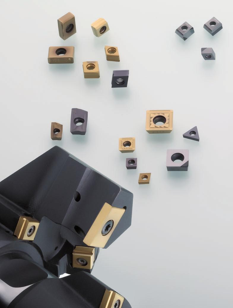
67 Tools with ISO elements Indexable inserts Radial and tangential indexable inserts MAPAL has a wide range of radial and tangential indexable inserts that covers all requirements for different cutting materials and coatings as well as the related cutting edge geometries and accuracies. Ground, highly accurate indexable inserts in tolerance class (H) make possible, in conjunction with precisely machined insert seats, the smallest variations between the cutting edges on multi-cutting edge tools, even in case of fixed installation, which provides a "real" multi-cutting edge capability and as a result permits significant performance increases. Sintered radial and tangential indexable inserts in tolerance class (M) expand the programme with particularly cost-effective alternatives, in particular for machining with larger permissible tolerances. Programme overview indexable inserts 68 Model key 72 Cutting material overview 76 Overview of chip guiding stages - boring 82 Indexable inserts boring 88 Indexable inserts milling 116 Special inserts 125 Through bore Suitable for open bores. Not suitable for machining shoulders if 90 angle is required. Blind bore Suitable for closed bores and machining shoulders taking into account the cutting edge length. Chamfering / countersinking Insert can be used for all chamfer angles. Not suitable for cutting stages, for example entry diameter on fits and threads. Indexable insert Introduction BS L00 BS L10 Arc shaped land - blind bore Special support surface on the cutting edges at 0 contact angle for quiet running and better surfaces. Arc shaped land - through bore Special support surface on the cutting edges at 10 contact angle for quiet running and better surfaces. 67
68 Tools with ISO elements Indexable inserts Overview Indexable inserts boring Tangential technology Insert type CTHD CTHQ FTHQ Features Number of cutting edges Insert size 06 / 09 / / 09 / / 09 / 12 Diameter range from 28 mm from 28 mm from 22 mm Cutting direction L / R L / R L L / R Boring-neutral n n n n n Boring-arc shaped land n n n Countersinking / chamfering Cutting material Roughing Medium machining Finishing Carbide PCD PcBN Ceramic Cermet Page n n n n n n n n n n n n n n n n n Radial technology Insert type CCMT - CCGT CCGW CCHT DCMT - DCGT - DCGW SPMT - SCMT - SCGT Features Number of cutting edges Insert size 06 / 09 / / / / 09 / / / 09 / / 09 Diameter range from 17 mm from 17 mm from 17 mm from 18.6 mm* from 17 mm Cutting direction N L / R N L / R L / R N N Boring-neutral n n n n n Boring-arc shaped land Countersinking / chamfering Application Application Cutting material 68 Roughing Medium machining Finishing Carbide PCD PcBN Ceramic Cermet Page n n n n n n n n n n n n n n n n n n n n n n n n n n *In case of favourable installation situation
69 Tools with ISO elements Indexable inserts Overview FTHQ FTHW STHD / STHE WTHQ / 09 / / / 09 from 22 mm from 60 mm from 37 mm L L N L / R n n n n n n n n n n n n n n n n n n n n n n n n n n n n SPGW - SCGW SPHT - SCHT SPHT - SCHT TCMT - TCGW TCHT VBMT - VCMT - VBGW - VCGT - VCGW Indexable insert Introduction / 09 / / / 09 / / 09 / / 11 / / 11 / / from 17 mm from 17 mm from 17 mm from 17 mm from 17 mm VB from 29.1 mm* / VC from 22.2 mm* N L / R N N L / R N N n n n n n n n n n n n n n n n n n n n n n n n n n n n n n n n n n
70 Tools with ISO elements Indexable inserts Overview Indexable inserts milling Insert type Tangential technology CTND CTHD CTHA Features Milling cutters Number of cutting edges Insert size Cutting direction Face milling cutters Shoulder milling cutters Disc milling cutters Porcupine milling cutters Helix milling cutters L / R L / R R n n n n n n n n n n n n n n n Application Roughing Medium machining Finishing n n n n n n n n Cutting material Carbide PCD PcBN n n n n n n n Page BDGT BDMT SEMT / / / 15 R R R n n n n n n n n n n n n n n n n n n n n n n
71 Tools with ISO elements Indexable inserts Overview CTMQ CTHQ CTHH LTHU R L / R R N n n n n n n n n n n n n n n n n n n n n n n n n n n n n n n n n n n Indexable insert Introduction 71
72 Tools with ISO elements Indexable inserts Designation key tangential Designation key tangential indexable inserts W T H Q Insert form Tolerance Insert type Insert size Insert thickness C (80 ) F (70 ) L (90 ) S (90 ) W (80 ) d H ±0,013 ±0,025 G ±0,025 ±0,13 N M d ±0,05 ±0,15 ±0,05 ±0,15 s ±0,025 ±0,13 s A D E H Q inscribed circle d d d d d l l l l l d (mm) W C F L S 6,35 06/ , ,525 09/ ,7 12/ ,65 09 Code s (mm) 03 3,18 T3 3, , , , ,94 U Corner radius Chamfer lead TFB W Code r (mm) Code Chamfer 00 0 MA 0,4x75 Indexable insert 04 0,4 08 0,8 MC 0,55x45 MG 1x ,2 20 2,0 30 3,0 T Tangential 72
73 Tools with ISO elements Indexable inserts Designation key tangential A 3 2 L 0 0 B H U Cutting direction Contact angle Cutting material L Boring Milling Left Arc shaped land HU615 R Code Angle Code Angle (Example) Right N Indexable insert Introduction Chip groove Arc shaped land Finishing cutting edge milling Code letter A B Code Length M018 1,8 C D G B B B B B CTHQ/FTHQ/WTHQ Code Radius M050 R 050 M100 R 100 H B B B FTHW 73
74 Tools with ISO elements Indexable inserts Designation key radial Designation key radial indexable inserts S C H T 0 9 T Insert form Tolerance Insert type Insert size Insert thickness S (90 ) C (80 ) T (60 ) D (55 ) d m s d d d d d d m s W H ±0,013 ±0,013 ±0,025 T G ±0,025 ±0,025 von ±0,05 bis ±0,13 * N von ±0,05 von ±0,08 ±0,025 bis ±0,15 * bis ±0,20 * Incircle l l l l l d (mm) B S C T D V 5, , , , , , , , Code s (mm) T1 1, , ,18 T3 3, ,76 V (35 ) M von ±0,05 bis ±0,15 * von ±0,08 bis ±0,20 * von ±0,05 bis ±0,13 * B (82 ) * Tolerance dependent of the insert size Corner radius Clearance angle C 7 P 11 D 15 E 20 Code r (mm) 02 0,2 04 0,4 08 0,8 12 1,2 16 1,6 20 2,0 24 2,4 31 3,1 40 4,0 74
75 Tools with ISO elements Indexable inserts Designation key radial Not required with sintered inserts F 0 1 L - U H U Ground indexable insert Cutting edge design Cutting direction Cutting material L Code letter Design HU615 Sharp edged Left R (Example) F 01 Right 01 E Rounded Bevelled N Neutral X Ground chip groove Sintered chip groove T 51 Right / left 1 R A U 3 0 Indexable insert Introduction Only with cutting edges fitted Chip groove Assembly Cutting edge design Code letter Code letter Design Code letter Design 0A 1R 2R Fitted on one side U Chip groove finishing 1L A 2L 5L 6L One corner or one cutting edge M Chip groove semi R Chip groove roughing 75
76 Tools with ISO elements Indexable inserts Cutting material overview Cutting material overview Cutting material Cutting material code Coating composition Coating colour Milling Turning Boring Reaming Recommended application Cermet CVD coated CC111 Al 2 O 3 Black Finest grain Cermet grade with Al 2 O 3 coating with the emphasis on finishing and semi-machining of steel and cast iron materials with elevated cutting speeds. CP130 TiAlN Blackanthracite Ultra-fine grain Cermet grade with TiAlN coating for finish machining steel and stainless steel with low to medium tensile strengths. CP131 AlTiN Blackanthracite Ultra-fine grain Cermet grade with AlTiN coating for finishing machining steel and stainless steel with medium to high tensile strengths, as well as grey cast iron and spheroidal graphite cast iron up to 500 N/mm 2. Cermet PVD coated CP871 AlTiN Black-red Ultra-fine grain Cermet with extremely heat-resistant PVD coating with excellent wear resistance and improved ductility for finishing steel and stainless steel. In case of stable conditions and high requirements on surface quality. CP872 AlTiN Black-red Ultra-fine grain Cermet with extremely heat-resistant PVD coating with a very balanced relationship between wear resistance and ductility for finishing and medium machining of steel and stainless steel. In case of slightly unstable conditions and slightly interrupted cuts. PcBN FU430 PcBN grade with high CBN-content for finishing and semi-finishing grey cast iron and sintered metal. HC840 TiCN+ Al 2 O 3 Black-grey Finest grain carbide with high wear resistance and a multi-layer CVD coating comprising TiCN with Al 2 O 3 function coating for finishing grey cast iron and spheroidal graphite cast iron at high cutting speeds. For smoother to slightly interrupted cut. HC841 TiCN+ Al 2 O 3 Black-grey Fine grain carbide with a multi-layer CVD coating made of TiCN and an Al 2 O 3 function coating. First choice for machining grey cast iron and spheroidal graphite cast iron with slightly to heavily interrupted cut. Carbide CVD coated HC851 HC852 TiCN+ Al 2 O 3 + TiN TiCN+ Al 2 O 3 + TiN Gold Gold Wear-free P substrate with a wear-resistant, multi-layer CVD coating made of TiCN, an Al 2 O 3 function coating and a very smooth TiN top coating. Finishing steel at high cutting speeds and smooth to slightly interrupted cut. P substrate with a good mixture of wear resistance and ductility, as well as a multi-layer CVD coating made of TiCN, an Al 2 O 3 function coating and a very smooth TiN top coating. General machining of steel with slightly to heavily interrupted cut and also high stock removal. HC861 TiCN+ Al 2 O 3 + TiN Gold Wear-resistant substrate with a multi-layer CVD coating made of TiCN, an Al 2 O 3 function coating and a very smooth TiN top coating. Specially for machining stainless steel with smooth to slightly interrupted cut. HC862 TiCN+ Al 2 O 3 + TiN Gold Carbide substrate with a good mixture of wear resistance and ductility, as well as a multilayer CVD coating made of TiCN, an Al 2 O 3 function coating and a very smooth TiN top coating. Specially for machining stainless steel with slightly to heavily interrupted cut and high stock removal. 76 Applications: Unstable machining / 1st choice General machining / 1st choice Stable machining / 1st choice Unstable machining / 2nd choice General machining / 2nd choice Stable machining / 2nd choice
77 Tools with ISO elements Indexable inserts Cutting material overview P M K N S Steel Stainless steel Cast iron Non-ferrous metals High temperature alloys and Harder More ductile Harder More ductile Harder More ductile Harder More ductile Harder titanium alloys More ductile Indexable insert Introduction 77
78 Tools with ISO elements Indexable inserts Cutting material overview Cutting material overview Cutting material Cutting material code Coating composition Coating colour Milling Turning Boring Reaming Recommended application HP118 AlTiN Blackanthracite Ductile finest grain carbide with PVD coating. Universal grade for turning and boring in the area of light to medium machining with interrupted cuts or in case of unstable conditions. Suitable for wet or dry machining. HP122 TiAlN Blackanthracite Wear-resistant finest grain carbide with PVD coating. Specially for fine machining steel and stainless steel with low and medium tensile strengths. HP141 AlTiN Blackanthracite Wear-resistant finest grain carbide with PVD coating. Specially for fine machining steel and stainless steel with higher tensile strengths as well as grey cast iron and spheroidal graphite cast iron. Suitable for wet or dry machining. HP182 TiAlN Blackanthracite Ductile finest grain carbide with PVD top coating. For boring in the area of roughing to semifinish machining with interrupted cuts or in case of unstable conditions. For steel and stainless steel with low to medium tensile strengths. Suitable for wet or dry machining. HP350 AlTiCrN Blackanthracite Ductile finest grain carbide with PVD top coating. Universal grade for milling and boring in the area of roughing to semi-finish machining with interrupted cuts or in case of unstable conditions. First choice for boring high strength steel and stainless steel with tangential inserts, as well as 1st choice for milling grey cast iron and spheroidal graphite cast iron using tangential inserts. Suitable for wet or dry machining. Carbide PVD coated HP382 HP454 TiAlN AlTiN Blackanthracite Blackanthracite Ductile finest grain carbide with PVD coating. For milling and boring in the area of roughing to semi-finish machining with interrupted cuts or in case of unstable conditions. For steel and stainless steel with low to medium tensile strengths. Suitable for wet or dry machining. Fine grain carbide with PVD coating. Universal grade for boring and reaming in the area of fine machining with low cutting depths also suitable for slightly interrupted cuts. HP455 AlTiCrN Blackanthracite Fine grain carbide with PVD top coating. Universal grade for boring in the area of semi-finish machining and roughing. Suitable for wet or dry machining. First choice for grey cast iron and spheroidal graphite cast iron machining using tangential inserts. HP615 TiB2 Silver-grey Fine grain carbide with a special PVD coating for machining adhesive materials. First choice for increasing tool life compared to uncoated cutting edges in aluminium alloys with 7-12 % Si as well as titanium. HP718 TiB2 Silver-grey Ductile finest grain carbide with a special PVD coating for machining adhesive materials in case of unstable conditions and significantly interrupted cuts. First choice for increasing tool life compared to uncoated cutting edges in aluminium alloys with 7-12 % Si as well as titanium. Ductile fine grain carbide with a very heat-resistant PVD coating for milling steel of any type. HP883 TiAlN+TiN Gold HP890 TiAlN Blue-violet Ductile fine grain carbide with PVD coating for milling grey cast iron, spheroidal graphite cast iron and titanium alloys. 78 Applications: Unstable machining / 1st choice General machining / 1st choice Stable machining / 1st choice Unstable machining / 2nd choice General machining / 2nd choice Stable machining / 2nd choice
79 Tools with ISO elements Indexable inserts Cutting material overview P M K N S Steel Stainless steel Cast iron Non-ferrous metals High temperature alloys and Harder More ductile Harder More ductile Harder More ductile Harder More ductile Harder titanium alloys More ductile Indexable insert Introduction 79
80 Tools with ISO elements Indexable inserts Cutting material overview Cutting material overview Cutting material Cutting material code Coating composition Coating colour Milling Turning Boring Reaming Recommended application HU615 Fine grain carbide with very smooth surface for general machining of aluminium wrought alloy and aluminium cast alloys with Si content < 7 %, as well as titanium alloys with lower cutting speeds. Carbide Uncoated HU810 Fine grain carbide with very smooth surface for machining aluminium wrought alloy and aluminium cast alloys with Si content < 7 %, as well as titanium alloys with lower cutting speeds in case of stable cutting conditions. HU825 Fine grain carbide with very smooth surface for milling aluminium wrought alloy and aluminium cast alloys with Si content < 7 %, as well as titanium alloys with lower cutting speeds in case of interrupted cuts. Ceramic KU450 The universal silicon nitride ceramic grade for machining grey cast iron workpiece materials in a particularly wide range of applications from roughing to semi-finish machining as well as with smooth or slightly interrupted cuts. PU617 PCD grade with medium particle size for roughing to semi-finish machining in non-ferrous metals and for machining very abrasive materials. PCD Fine grain PCD grade for finishing non-ferrous metals. PU620 Applications: Unstable machining / 1st choice General machining / 1st choice Stable machining / 1st choice Unstable machining / 2nd choice General machining / 2nd choice Stable machining / 2nd choice 80
81 Tools with ISO elements Indexable inserts Cutting material overview P M K N S Steel Stainless steel Cast iron Non-ferrous metals High temperature alloys and Harder More ductile Harder More ductile Harder More ductile Harder More ductile Harder titanium alloys More ductile Indexable insert Introduction 81
82 Tools with ISO elements Indexable inserts Chip breaker forms overview Overview of chip breaker forms boring Tangential indexable inserts Type ISO 513 Edge rounding Diagram A P M K +++ a p N 1 S 0 0 0,1 0,2 0,3 0,4 f (mm/z) A81 14 P M K + a p N 1 Roughing D S P M K ,1 0,2 0,3 0,4 f (mm/z) a p N 1 S 0 0 0,1 0,2 0,3 0,4 f (mm/z) H P M K +++ a p N ,1 0,2 0,3 0,4 f (mm/z) A31 18 P M K + a p N 1 Medium machining roughing A32 18 A80 14 S P M K N S P M K ,1 0,2 0,3 0,4 f (mm/z) a p ,1 0,2 0,3 0,4 f (mm/z) a p N 1 S 0 0 0,1 0,2 0,3 0,4 f (mm/z) 82
83 Tools with ISO elements Indexable inserts Chip breaker forms overview 0 = Sharp edged + = Slightly rounded ++ = Medium rounded +++ = Heavily rounded Type ISO 513 Edge rounding Diagram A30 18 P M K 0 a p N 1 S 0 0 0,1 0,2 0,3 0,4 f (mm/z) A50 13 P M K +++ a p N 1 S 0 0 0,1 0,2 0,3 0,4 f (mm/z) Medium machining A56 20 P M K N S +++ a p ,1 0,2 0,3 0,4 f (mm/z) A79 8 P M K 0 a p N 1 A88 8 S P M K ,1 0,2 0,3 0,4 f (mm/z) a p Indexable insert Boring N 1 S 0 0 0,1 0,2 0,3 0,4 f (mm/z) 83
84 Tools with ISO elements Indexable inserts Chip guiding stage overview Overview of chip breaker forms boring Tangential indexable inserts Type ISO 513 Edge rounding Diagram C00 6 P M K 0 a p N 1 S 0 0 0,1 0,2 0,3 0,4 f (mm/z) Finishing C60 0 P M K N 0 a p S 0 0 0,1 0,2 0,3 0,4 f (mm/z) C61 0 P M K 0 a p N 1 S 0 0 0,1 0,2 0,3 0,4 f (mm/z) D00 P M K N 0 a p is dependent on indexable insert type f z = 0, S D01 P Of universal application D M K N S P M K N + ++ a p is dependent on indexable insert type f z = 0, a p is dependent on indexable insert type f z = 0, S D03 P M K N +++ a p is dependent on indexable insert type f z =
85 Tools with ISO elements Indexable inserts Chip breaker forms overview Overview of chip breaker forms boring Radial indexable inserts 0 = Sharp edged + = Slightly rounded ++ = Medium rounded +++ = Heavily rounded Type ISO 513 Edge rounding Diagram Medium machining roughing R P M K N S +++ a p ,1 0,2 0,3 0,4 f (mm/z) 0A* P M 0 K N + ++ a p S 0 0 0,1 0,2 0,3 0,4 f (mm/z) 0AA* 0 P M K N S a p ,1 0,2 0,3 0,4 f (mm/z) Medium machining finishing 1L* P M 10 K N S 1R* P M 15 K N a p ,1 0,2 0,3 0,4 f (mm/z) a p Indexable insert Boring S 0 0 0,1 0,2 0,3 0,4 f (mm/z) 2L* P M 10 K N + ++ a p S 0 0 0,1 0,2 0,3 0,4 f (mm/z) 6LA 10 P M K 0 a p N 1 S 0 0 0,1 0,2 0,3 0,4 f (mm/z) * This chip breaker form is available with different edge rounding. 85
86 Tools with ISO elements Indexable inserts Chip breaker forms overview Overview of chip breaker forms boring Radial indexable inserts Type ISO 513 Edge rounding Diagram 2R* P 15 M K N 0 + a p S 0 0 0,1 0,2 0,3 0,4 f (mm/z) 5 M P M K ++ a p N 1 Medium machining finishing M31 17 M S P M K N S P M K ,1 0,2 0,3 0,4 f (mm/z) a p ,1 0,2 0,3 0,4 f (mm/z) a p N 1 S 0 0 0,1 0,2 0,3 0,4 f (mm/z) U Section through radius Section through main cutting edge P M K N S ++ a p ,1 0,2 0,3 0,4 f (mm/z) * This chip breaker form is available with different edge rounding. 86
87 Tools with ISO elements Indexable inserts Chip breaker forms overview 0 = Sharp edged + = Slightly rounded ++ = Medium rounded +++ = Heavily rounded Type ISO 513 Edge rounding Diagram 5LA 10 P M K 0 a p N 1 S 0 0 0,1 0,2 0,3 0,4 f (mm/z) Finishing U U Section through radius Section through main cutting edge Section through radius Section through main cutting edge P M K N S P M K N S + ++ a p ,1 0,2 0,3 0,4 f (mm/z) a p ,1 0,2 0,3 0,4 f (mm/z) U30 20 P M K ++ a p N 1 S 0 0 0,1 0,2 0,3 0,4 f (mm/z) Indexable insert Boring 87
88 Tools with ISO elements Indexable inserts Boring Tangential indexable inserts, two-cutting edges CTHD Boring without arc shaped land Tipped variant one-cutting edge Carbide PCD P M K N S N Roughing Cutting material Cutting edge design D03 D03 D01 D02 D80 from ø 28 mm a p (mm) CTHD L- 1,5-3 CTHD R- 1,5-3 CTHD L- 1,5-3 CTHD R- 1,5-3 from ø 41 mm CTHD 09T304...L- 1,5-4 CTHD 09T304...R- 1,5-4 CTHD 09T308...L- 1,5-4 CTHD 09T308...R- 1,5-4 CTHD 09T312...L- 1,5-4 CTHD 09T312...R- 1,5-4 from ø 54 mm CTHD L- 1,5-5 CTHD R- 1,5-5 CTHD L- 1,5-5 CTHD R- 1,5-5 CTHD L- 1,5-5 CTHD R- 1,5-5 HP455 HP350 HU615 HP615 PU617 Note: For general figures for the minimum boring diameter in connection with the number of teeth see section Technical appendix page 179. For clamping screws and screwdriver for indexable inserts see section Accessories page 167. Ordering example: On ordering please add the selected cutting edge design and the cutting material to the designation key. CTHD090304D03L-HP455 Cutting rate see page 184. Available from stock in Germany. Standard insert not carried in stock. (Delivery time upon request). 88
89 Tools with ISO elements Indexable inserts Boring Tangential indexable inserts, two-cutting edges CTHD Boring without arc shaped land Carbide P M K N S Medium machining Cutting material Cutting edge design D02 D02 D00 D01 from ø 28 mm a p (mm) CTHD L- 1,5-3 CTHD R- 1,5-3 CTHD L- 1,5-3 CTHD R- 1,5-3 from ø 41 mm CTHD 09T304...L- 1,5-4 CTHD 09T304...R- 1,5-4 CTHD 09T308...L- 1,5-4 CTHD 09T308...R- 1,5-4 CTHD 09T312...L- 1,5-4 CTHD 09T312...R- 1,5-4 from ø 54 mm CTHD L- 1,5-5 CTHD R- 1,5-5 CTHD L- 1,5-5 CTHD R- 1,5-5 CTHD L- 1,5-5 CTHD R- 1,5-5 HP455 HP350 HU615 HP615 Indexable insert Boring Note: For general figures for the minimum boring diameter in connection with the number of teeth see section Technical appendix page 179. For clamping screws and screwdriver for indexable inserts see section Accessories page 167. Ordering example: On ordering please add the selected cutting edge design and the cutting material to the model. CTHD060304D02L-HP455 Cutting rate see page 184. Available from stock in Germany. Standard insert not carried in stock. (Delivery time upon request). 89
90 Tools with ISO elements Indexable inserts Boring Tangential indexable inserts, four-cutting edges BS L00 CTHQ Boring blind bore with arc shaped land Tipped variant one-cutting edge Carbide PcBN PCD P M K N S K N Roughing Medium machining HP182 HP382 HP382 HP118 Cutting material Cutting edge design A54 A54 A32 A32 H03 H03 A31 A32 A81 A80 from ø 40 mm a p (mm) CTHQ L00B ,0-2,5 from ø 65 mm CTHQ L00B ,5-3 1,5-4 CTHQ L00B ,5-3 1,5-4 from ø 78 mm CTHQ L00B ,5-3 1,5-5 CTHQ L00B ,5-3 1,5-5 Cutting edge design A50 A50 A56 A56 A32 A32 A30 A31 A31 A88 A79 A80 from ø 40 mm a p (mm) CTHQ L00B ,5-2 CTHQ L00B ,5-2 from ø 65 mm CTHQ L00B ,5-2 CTHQ L00B ,5-2 CTHQ L00B ,5-2 from ø 78 mm CTHQ L.00B ,5-2 CTHQ L.00B ,5-2 CTHQ L00B ,5-2 HP455 HP350 HU615 HP615 HP718 FU430 PU617 PU617 Right handed design on request. Note: For general figures for the minimum boring diameter in connection with the number of teeth see section Technical appendix page 179. For clamping screws and screwdriver for indexable inserts see section Accessories page 167. Ordering example: On ordering please add the selected cutting edge design and the cutting material to the designation key. CTHQ060408A54L00B016-HP182 Cutting rate see page 184. Available from stock in Germany. Standard insert not carried in stock. (Delivery time upon request). 90
91 Tools with ISO elements Indexable inserts Boring Tangential indexable inserts, four-cutting edges BS L10 CTHQ Boring through bore with arc shaped land Tipped variant one-cutting edge Carbide PcBN PCD P M K N S K N Roughing HP182 HP382 HP382 HP118 Cutting material Cutting edge design A54 A54 A32 A32 H03 H03 A31 A32 A81 A80 from ø 40 mm a p (mm) CTHQ L10B ,0-2,5 from ø 65 mm CTHQ L10B ,5-3 1,5-4 from ø 78 mm CTHQ L10B081-1,5-3 1,5-5 HP455 HP350 HU615 HP615 HP718 FU430 PU617 PU617 Medium machining Cutting edge design A50 A50 A56 A56 A32 A32 A30 A31 A31 A88 A79 A80 from ø 40 mm a p (mm) CTHQ L10B ,5-2 CTHQ L10B ,5-2 from ø 65 mm CTHQ L10B ,5-2 CTHQ L10B ,5-2 from ø 78 mm CTHQ L10B081-0,5-2 CTHQ L10B081-0,5-2 Indexable insert Boring Right design on request. Note: For general figures for the minimum boring diameter in connection with the number of teeth see section Technical appendix page 179. For clamping screws and screwdriver for indexable inserts see section Accessories page 167. Ordering example: On ordering please add the selected cutting edge design and the cutting material to the designation key. CTHQ060408A54L10B016-HP182 Cutting rate see page 184. Available from stock in Germany. Standard insert not carried in stock. (Delivery time upon request). 91
92 Tools with ISO elements Indexable inserts Boring Tangential indexable inserts, four-cutting edges CTHQ Boring neutral without arc shaped land Tipped variant one-cutting edge Carbide PcBN PCD P M K N S K N Roughing Medium machining HP182 HP382 HP382 HP118 Cutting material Cutting edge design A54 A54 A32 A32 H03 H03 A31 A32 A81 A80 from ø 28 mm a p (mm) CTHQ L-... 1,0-2,5 CTHQ R-... 1,0-2,5 from ø 41 mm CTHQ L-... 1,5-3 1,5-4 CTHQ R-... 1,5-3 1,5-4 from ø 54 mm CTHQ L- 1,5-3 1,5-5 CTHQ R-... 1,5-3 1,5-5 Cutting edge design A50 A50 A56 A56 A32 A32 A30 A31 A31 A88 A79 A80 from ø 28 mm a p (mm) CTHQ L-... 0,5-2 CTHQ R-... 0,5-2 from ø 41 mm CTHQ L-... 0,5-2 CTHQ R-... 0,5-2 CTHQ L-... 0,5-2 CTHQ R- 0,5-2 from ø 54 mm CTHQ L-... 0,5-2 CTHQ R- 0,5-2 HP455 HP350 HU615 HP615 HP718 FU430 PU617 PU617 Note: For general figures for the minimum boring diameter in connection with the number of teeth see section Technical appendix page 179. For clamping screws and screwdriver for indexable inserts see section Accessories page 167. Ordering example: On ordering please add the selected cutting edge design and the cutting material to the designation key. CTHQ060408A54L-HP182 Cutting rate see page 184. Available from stock in Germany. Standard insert not carried in stock. (Delivery time upon request). 92
93 Tools with ISO elements Indexable inserts Boring Tangential indexable inserts, four-cutting edges BS L00 FTHQ Boring blind bore with arc shaped land Tipped variant one-cutting edge Roughing from ø 30 mm FTHQ L00B FTHQ L00B from ø 40 mm FTHQ L00B FTHQ L00B HP182 Carbide PcBN PCD P M K N S K N HP382 HP382 HP118 HP455 HP350 Cutting material Cutting edge design A54 A54 A32 A32 H03 H03 A31 A32 A81 A80 a p (mm) 1,5-3 1,5-4 1,5-3 1,5-4 1,5-3 1,5-5 1,5-3 1,5-5 HU615 HP615 HP718 FU430 PU617 PU617 Medium machining Cutting edge design A50 A50 A56 A56 A32 A32 A30 A31 A31 A88 A79 A80 from ø 22 mm a p (mm) FTHQ L00B ,5-1,5 FTHQ L00B ,5-1,5 from ø 30 mm FTHQ L00B ,5-2 FTHQ L00B ,5-2 from ø 40 mm FTHQ L00B ,5-2 FTHQ L00B ,5-2 FTHQ L00B ,5-2 Indexable insert Boring Right handed design on request. Note: For general figures for the minimum boring diameter in connection with the number of teeth see section Technical appendix page 179. For clamping screws and screwdriver for indexable inserts see section Accessories page 167. Ordering example: On ordering please add the selected cutting edge design and the cutting material to the designation key. FTHQ060408A54L00B012-HP182 Cutting rate see page 184. Available from stock in Germany. Standard insert not carried in stock. (Delivery time upon request). 93
94 Tools with ISO elements Indexable inserts Boring Tangential indexable inserts, four-cutting edges BS L10 FTHQ Boring through bore with arc shaped land Tipped variant one-cutting edge Roughing from ø 30 mm FTHQ L10B from ø 40 mm FTHQ L10B HP182 Carbide PcBN PCD P M K N S K N HP382 HP382 HP118 HP455 HP350 Cutting material Cutting edge design A54 A54 A32 A32 H03 H03 A31 A32 A81 A80 a p (mm) 1,5-3 1,5-4 1,5-3 1,5-5 HU615 HP615 HP718 FU430 PU617 PU617 Medium machining Cutting edge design A50 A50 A56 A56 A32 A32 A30 A31 A31 A88 A79 A80 from ø 22 mm a p (mm) FTHQ L10B ,5-1,5 FTHQ L10B ,5-1,5 from ø 30 mm FTHQ L10B ,5-2 FTHQ L10B ,5-2 from ø 40 mm FTHQ L10B ,5-2 FTHQ L10B ,5-2 Right handed design on request. Note: For general figures for the minimum boring diameter in connection with the number of teeth see section Technical appendix page 179. For clamping screws and screwdriver for indexable inserts see section Accessories page 167. Ordering example: On ordering please add the selected cutting edge design and the cutting material to the designation key. FTHQ060408A54L10B012-HP182 Cutting rate see page 184. Available from stock in Germany. Standard insert not carried in stock. (Delivery time upon request). 94
95 Tools with ISO elements Indexable inserts Boring Tangential indexable inserts, four-cutting edges FTHQ Boring neutral without arc shaped land Tipped variant one-cutting edge Roughing from ø 30 mm FTHQ L-... FTHQ R-... from ø 40 mm FTHQ L-... FTHQ R-... HP182 Carbide PcBN PCD P M K N S K N HP382 HP382 HP118 HP455 HP350 Cutting material Cutting edge design A54 A54 A32 A32 H03 H03 A31 A32 A81 A80 a p (mm) 1,5-3 1,5-4 1,5-3 1,5-4 1,5-3 1,5-5 1,5-3 1,5-5 HU615 HP615 HP718 FU430 PU617 PU617 Medium machining Cutting edge design A50 A50 A56 A56 A32 A32 A30 A31 A31 A88 A79 A80 from ø 22 mm a p (mm) FTHQ L-... 0,5-1,5 FTHQ R-... 0,5-1,5 FTHQ L-... 0,5-1,5 FTHQ R-... 0,5-1,5 from ø 30 mm FTHQ L-... 0,5-2 FTHQ R-... 0,5-2 FTHQ L-... 0,5-2 FTHQ R-... 0,5-2 from ø 40 mm FTHQ L-... 0,5-2 FTHQ R-... 0,5-2 FTHQ L-... 0,5-2 Indexable insert Boring Note: For general figures for the minimum boring diameter in connection with the number of teeth see section Technical appendix page 179. For clamping screws and screwdriver for indexable inserts see section Accessories page 167. Ordering example: On ordering please add the selected cutting edge design and the cutting material to the designation key. FTHQ060408A54L-HP182 Cutting rate see page 184. Available from stock in Germany. Standard insert not carried in stock. (Delivery time upon request). 95
96 Tools with ISO elements Indexable inserts Boring Tangential indexable inserts, two-cutting edges FTHW Fine boring with arc shaped land not face cutting Tipped variant one-cutting edge Carbide Cermet PcBN PCD P M K N S P K K N Cutting material HP122 HP141 HP141 HP122 HP141 HP454 HU615 HP615 CP130 CP131 FU430 PU620 Finishing from ø 60 mm a p (mm) FTHW 0905MGC00L00B030-0,1-0,5 FTHW 0905MCC00L00B030-0,1-0,5 FTHW 0905MAD00L00B030-0,1-0,5 FTHW 0905MGD01L00B030-0,1-0,5 FTHW 0905MCD01L00B030-0,1-0,5 FTHW 0905MCD00L00B030-0,1-0,5 FTHW 0905MAC60L00B030-0,1-0,5 FTHW 0905MCC61L00B030-0,1-0,5 from ø 120 mm FTHW 0905MGC00L00B060-0,1-0,5 FTHW 0905MCC00L00B060-0,1-0,5 FTHW 0905MAD00L00B060-0,1-0,5 FTHW 0905MGD01L00B060-0,1-0,5 FTHW 0905MCD01L00B060-0,1-0,5 FTHW 0905MCD00L00B060-0,1-0,5 FTHW 0905MAC60L00B060-0,1-0,5 FTHW 0905MCC61L00B060-0,1-0,5 from ø 180 mm FTHW 0905MGC00L00B090-0,1-0,5 FTHW 0905MCC00L00B090-0,1-0,5 FTHW 0905MAD00L00B090-0,1-0,5 FTHW 0905MGD01L00B090-0,1-0,5 FTHW 0905MCD01L00B090-0,1-0,5 FTHW 0905MCD00L00B090-0,1-0,5 FTHW 0905MAC60L00B090-0,1-0,5 FTHW 0905MCC61L00B090-0,1-0,5 Right handed design on request. Note: The minimum boring diameter is dependent on the arc shaped land design. For clamping screws and screwdriver for indexable inserts see section Accessories page 167. Ordering example: On ordering please add the selected cutting material to the designation key. FTHW0905MGC00L00B030-HP122 Cutting rate see page 187. Available from stock in Germany. Standard insert not carried in stock. (Delivery time upon request). 96
97 Tools with ISO elements Indexable inserts Boring Tangential indexable inserts, four-cutting edges STHD - STHE Chamfering Tipped variant one-cutting edge Carbide PCD P M K N S N Chamfering HP455 Cutting material Cutting edge design D02 D02 D02 D00 D80 a p (mm) STHD N- 0,1-4,2 STHE N- 0,1-4,2 STHD 09T300...N- 0,1-6,3 STHE 09T300...N- 0,1-6,3 HP455 HP455 HU615 PU617 Indexable insert Boring Note: General figures for the minimum boring diameter in connection with the installation situation. For clamping screws and screwdriver for indexable inserts see section Accessories page 167. Ordering example: On ordering please add the selected cutting edge design and the cutting material to the designation key. STHD060300D02N-HP455 Cutting rate see page 184. Available from stock in Germany. Standard insert not carried in stock. (Delivery time upon request). 97
98 Tools with ISO elements Indexable inserts Boring Tangential indexable inserts, six-cutting edges BS L00 WTHQ Boring blind bore with arc shaped land Tipped variant one-cutting edge Carbide Ceramic PcBN PCD P M K N S K K N Roughing Medium machining HP182 HP382 HP382 HP118 Cutting material Cutting edge design A54 A54 A32 A32 H03 H03 A31 A32 H03 A80 from ø 37 mm a p (mm) WTHQ L00B ,5-3 WTHQ L00B ,5-3 from ø 59,5 mm WTHQ L00B ,5-3 1,5-5 WTHQ L00B ,5-3 1,5-5 from ø mm WTHQ L00B081-1,5-3 1,5-5 WTHQ L00B081-1,5-3 1,5-5 Cutting edge design A50 A50 A56 A56 A32 A32 A30 A31 A31 A88 A79 A80 from ø 37 mm a p (mm) WTHQ L00B ,5-2 WTHQ L00B ,5-2 from ø 59,5 mm WTHQ L00B ,5-2 WTHQ L00B ,5-2 from ø mm WTHQ L00B081-0,5-2 WTHQ L00B081-0,5-2 HP455 HP350 HU615 HP615 HP718 KU450 FU430 PU617 PU617 Right handed design on request. Note: For general figures for the minimum boring diameter in connection with the number of teeth see section Technical appendix page 179. For clamping screws and screwdriver for indexable inserts see section Accessories page 167. Ordering example: On ordering please add the selected cutting edge design and the cutting material to the designation key. WTHQ070504A54L00B026-HP182 Cutting rate see page 186. Available from stock in Germany. Standard insert not carried in stock. (Delivery time upon request). 98
99 Tools with ISO elements Indexable inserts Boring Tangential indexable inserts, six-cutting edges BS L10 WTHQ Boring through bore with arc shaped land Tipped variant one-cutting edge HP182 Carbide Ceramic PcBN PCD P M K N S K K N HP382 HP382 HP118 Cutting material Cutting edge design A54 A54 A32 A32 H03 H03 A31 A32 H03 A80 a p (mm) WTHQ L10B ,5-3 WTHQ L10B ,5-3 HP455 HP350 HU615 HP615 HP718 KU450 FU430 PU617 PU617 WTHQ L10B WTHQ L10B WTHQ L10B081- WTHQ L10B081-1,5-3 1,5-5 1,5-3 1,5-5 1,5-3 1,5-5 1,5-3 1,5-5 A50 A50 A56 A56 A32 A32 A30 A31 A31 A88 A79 A80 a p (mm) WTHQ L10B ,5-2 WTHQ L10B ,5-2 WTHQ L10B ,5-2 WTHQ L10B ,5-2 Indexable insert Boring WTHQ L10B081-0,5-2 WTHQ L10B081-0,5-2 Right handed design on request. Note: For general figures for the minimum boring diameter in connection with the number of teeth see section Technical appendix page 179. For clamping screws and screwdriver for indexable inserts see section Accessories page 167. Ordering example: On ordering please add the selected cutting edge design and the cutting material to the designation key. WTHQ070504A54L10B026-HP182 Cutting rate see page 186. Available from stock in Germany. Standard insert not carried in stock. (Delivery time upon request). 99
 WTHQ 070504...L-... 1,5-3 WTHQ 070504.")
100 Tools with ISO elements Indexable inserts Boring Tangential indexable inserts, six-cutting edges WTHQ Boring neutral without arc shaped land Tipped variant one-cutting edge Carbide Ceramic PcBN PCD P M K N S K K N Roughing Medium machining HP182 HP382 HP382 HP118 Cutting material Cutting edge design A54 A54 A32 A32 H03 H03 A31 A32 H03 A80 from ø 37 a p (mm) WTHQ L-... 1,5-3 WTHQ R-... 1,5-3 WTHQ L-... 1,5-3 WTHQ R-... 1,5-3 from ø 59.5 WTHQ L-... 1,5-3 1,5-5 WTHQ R-... 1,5-3 1,5-5 WTHQ L- 1,5-3 1,5-5 WTHQ R-... 1,5-3 1,5-5 Cutting edge design A50 A50 A56 A56 A32 A32 A30 A31 A31 A88 A79 A80 from ø 37 a p (mm) WTHQ L-... 0,5-2 WTHQ R-... 0,5-2 WTHQ L-... 0,5-2 WTHQ R-... 0,5-2 WTHQ L-... 0,5-2 WTHQ R-... 0,5-2 WTHQ L-... 0,5-2 WTHQ R-... 0,5-2 HP455 HP350 HU615 HP615 HP718 KU450 FU430 PU617 PU617 Note: For general figures for the minimum boring diameter in connection with the number of teeth see section Technical appendix page 179. For clamping screws and screwdriver for indexable inserts see section Accessories page 167. Ordering example: On ordering please add the selected cutting edge design and the cutting material to the designation key. WTHQ070504A54L-HP182 Cutting rate see page 186. Available from stock in Germany. Standard insert not carried in stock. (Delivery time upon request). 100
101 Tools with ISO elements Indexable inserts Boring Radial indexable inserts, two-cutting edges CCMT - CCGT Boring Tipped variant one-cutting edge 6LA Carbide PCD P M K N S P N 5LA Cutting material HC851 HC852 HC861 HC862 HC840 HC841 HU810 CP871 CP872 CC111 PU620 Medium mach'g Medium machining - finishing Finishing Medium machining - finishing a p (mm) CCMT 09T308N-R ,0-4,0 CCMT N-R ,0-6,0 CCMT N-M ,0-2,5 CCMT 09T304N-M ,0-3,0 CCMT 09T308N-M ,0-3,0 CCMT N-M ,0-3,0 CCMT N-M ,25-2,5 CCMT N-M ,5-2,5 CCMT 09T304N-M ,5-2,5 CCMT 09T308N-M ,75-2,5 CCMT 09T304N-U ,25-2,0 CCMT 09T308N-U ,5-2,0 CCGT 09T304N-M ,5-3,0 CCGT 09T308N-M ,5-3,0 CCGT N-U ,1-0,5 CCGT N-U ,2-0,5 CCGT F01L-6LA-... 0,1-3,0 CCGT F01R-6LA-... 0,1-3,0 CCGT F01L-6LA-... 0,1-3,0 CCGT F01R-6LA-... 0,1-3,0 CCGT 09T304F01L-6LA-... 0,1-4,5 CCGT 09T304F01R-6LA-... 0,1-4,5 CCGT 09T308F01L-6LA-... 0,1-4,5 CCGT 09T308F01R-6LA-... 0,1-4,5 Indexable insert Boring Finishing CCGT F01N-5LA-... 0,1-1,0 CCGT F01N-5LA-... 0,1-1,5 CCGT 09T304F01N-5LA-... 0,1-2,0 CCGT 09T308F01N-5LA-... 0,1-2,0 Note: For general figures for the minimum boring diameter in connection with the number of teeth see section Technical appendix page 178. For clamping screws and screwdriver for indexable inserts see section Accessories page 166. Ordering example: On ordering please add the selected cutting material to the designation key. CCMT09T308N-R30-HC851 Cutting rate see page 184. Available from stock in Germany. Standard insert not carried in stock. (Delivery time upon request). 101
102 Tools with ISO elements Indexable inserts Boring Radial indexable inserts, two-cutting edges CCGW Boring Tipped variant one-cutting edge Carbide PcBN PCD P M K N S K N Cutting material HP455 HP454 HU615 HP615 FU430 PU617 PU620 Medium machining a p (mm) CCGW E04N-0A-... 0,5-3,2 CCGW E04N-0A-... 0,5-3,2 CCGW 09T304E04N-0A-... 0,5-4,0 CCGW 09T308E04N-0A-... 0,5-4,0 CCGW 09T312E04N-0A-... 0,5-4,0 CCGW T51N-0AA-... 0,5-2,0 CCGW 09T304T51N-0AA-... 0,5-2,5 CCGW 09T308T51N-0AA-... 0,5-2,5 CCGW E01N-0AA-... 0,5-1,5 CCGW 09T304E01N-0AA-... 0,5-2,0 CCGW 09T308E01N-0AA-... 0,5-2,0 CCGW E02N-0A-... 0,2-1,0 CCGW E02N-0A-... 0,2-1,0 CCGW 09T304E02N-0A-... 0,2-2,0 CCGW 09T308E02N-0A-... 0,2-2,0 Finishing CCGW E01N-0AA-... 0,1-1,0 CCGW 09T304E01N-0AA-... 0,1-1,0 CCGW 09T308E01N-0AA-... 0,1-1,0 CCGW F01N-0AA-... 0,1-1,0 CCGW F01N-0AA-... 0,1-1,0 CCGW 09T304F01N-0AA-... 0,1-1,0 CCGW 09T308F01N-0AA-... 0,1-1,0 Note: For general figures for the minimum boring diameter in connection with the number of teeth see section Technical appendix page 178. For clamping screws and screwdriver for indexable inserts see section Accessories page 166. Available from stock in Germany. Standard insert not carried in stock. (Delivery time upon request). Ordering example: On ordering please add the selected cutting material to the designation key. CCGW060204E04N-0A-HP455 Cutting rate see page
103 Tools with ISO elements Indexable inserts Boring Radial indexable inserts, two-cutting edges CCHT Boring, left design Carbide P M K N S Cutting material Cutting edge design 1L 1L 1R 1R a p (mm) CCHT E04L ,5-3,2 CCHT E04L ,5-3,2 HP455 HP454 HU615 HP615 Medium machining CCHT 09T304E04L ,5-4,0 CCHT 09T308E04L ,5-4,0 CCHT 09T312E04L ,5-4,0 CCHT E04L ,5-5,0 CCHT E04L ,5-5,0 CCHT E04L ,5-5,0 Finishing Cutting edge design 1L 1L 1R 1R a p (mm) CCHT E02L ,1-1 CCHT E02L ,1-1 CCHT F01L ,1-1 CCHT F01L ,1-1 CCHT F01L ,1-1 CCHT 09T304E02L ,1-2 CCHT 09T308E02L ,1-2 CCHT 09T302F01L ,1-2 CCHT 09T304F01L ,1-2 CCHT 09T308F01L ,1-2 CCHT 09T312F01L ,1-2 CCHT F01L ,1-3 CCHT F01L ,1-3 CCHT F01L ,1-3 CCHT F01L ,1-3 Indexable insert Boring Note: For general figures for the minimum boring diameter in connection with the number of teeth see section Technical appendix page 178. For clamping screws and screwdriver for indexable inserts see section Accessories page 166. Ordering example: On ordering please add the selected cutting edge design and the cutting material to the designation key. CCHT060204E04L-1L-HP455 Cutting rate see page 184. Available from stock in Germany. Standard insert not carried in stock. (Delivery time upon request). 103
104 Tools with ISO elements Indexable inserts Boring Radial indexable inserts, two-cutting edges CCHT Boring, right design Carbide P M K N S Cutting material Cutting edge design 1L 1L 1R 1R a p (mm) CCHT E04R ,5-3,2 CCHT E04R ,5-3,2 HP455 HP454 HU615 HP615 Medium machining CCHT 09T304E04R ,5-4,0 CCHT 09T308E04R ,5-4,0 CCHT 09T312E04R ,5-4,0 CCHT E04R ,5-5,0 CCHT E04R ,5-5,0 CCHT E04R ,5-5,0 Cutting edge design 1L 1L 1R 1R a p (mm) CCHT E02R ,1-1 CCHT E02R ,1-1 CCHT F01R ,1-1 CCHT F01R ,1-1 CCHT F01R ,1-1 Finishing CCHT 09T304E02R ,1-2 CCHT 09T308E02R ,1-2 CCHT 09T302F01R ,1-2 CCHT 09T304F01R ,1-2 CCHT 09T308F01R ,1-2 CCHT 09T312F01R ,1-2 CCHT F01R ,1-3 CCHT F01R ,1-3 CCHT F01R ,1-3 CCHT F01R ,1-3 Note: For general figures for the minimum boring diameter in connection with the number of teeth see section Technical appendix page 178. For clamping screws and screwdriver for indexable inserts see section Accessories page 166. Ordering example: On ordering please add the selected cutting edge design and the cutting material to the designation key. CCHT060204E04R-1L-HP455 Cutting rate see page 184. Available from stock in Germany. Standard insert not carried in stock. (Delivery time upon request). 104
105 Tools with ISO elements Indexable inserts Boring Radial indexable inserts, two-cutting edges DCMT - DCGT - DCGW Boring Tipped variant one-cutting edge Carbide Cermet PcBN PCD P M K N S P K N Cutting material HC851 HC852 HC861 HC862 HC840 HC841 HU810 CP871 CP872 FU430 PU620 Medium machining finishing Finishing a p (mm) DCMT N-M ,5-2,0 DCMT N-M ,75-2,0 DCMT 11T302N-M ,5-3,0 DCMT 11T304N-M ,5-3,0 DCMT 11T308N-M ,75-3,0 DCMT N-M ,5-1,5 DCMT N-M ,75-1,5 DCMT 11T302N-M ,5-2,0 DCMT 11T304N-M ,5-2,0 DCMT 11T308N-M ,75-2,0 DCMT N-U ,25-1,5 DCMT N-U ,25-1,5 DCMT 11T302N-U ,25-2,0 DCMT 11T304N-U ,25-2,0 DCMT 11T308N-U ,5-2,0 DCGT 11T304N-M ,5-3,0 DCGT 11T308N-M ,5-3,0 DCMT N-U ,25-1,0 DCMT 11T302N-U ,25-1,0 DCMT 11T304N-U ,25-1,0 DCMT 11T308N-U ,5-1,0 DCGW11T304E01N-0AA-... 0,1-1,0 DCGW11T308E01N-0AA-... 0,1-1,0 DCGW 11T304F01N-0AA-... 0,1-1,0 DCGW 11T308F01N-0AA-... 0,1-1,0 Indexable insert Boring Note: General figures for the minimum boring diameter in connection with the installation situation. For clamping screws and screwdriver for indexable inserts see section Accessories page 166. Ordering example: On ordering please add the selected cutting material to the designation key. DCMT070204N-M31-HC852 Cutting rate see page 184. Available from stock in Germany. Standard insert not carried in stock. (Delivery time upon request). 105
106 Tools with ISO elements Indexable inserts Boring Radial indexable inserts, four-cutting edges SCMT - SPMT - SCGT - SPGT Boring Tipped variant one-cutting edge 6LA 5LA Carbide Cermet PCD P M K N S P N Cutting material HC851 HC852 HC861 HC862 HC840 HC841 CP871 CP872 CC111 PU620 Medium Mach Finishing medium machining a p (mm) SCMT 09T308N-R ,0-4,0 SCMT N-R ,0-6,0 SPMT N-M ,5-2,5 SCMT 09T304N-M ,5-2,5 SCMT 09T308N-M ,75-2,5 SCMT N-M ,75-3,0 SPMT N-U30_... 0,25-1,0 SCMT 09T304N-U ,25-1,0 SCGT 09T304N-U ,1-0,5 SCGT 09T308N-U ,1-0,5 SCGT 09T304N-U ,2-0,5 SCGT 09T308N-U ,2-0,5 Finishing SPGT F01L-6LA-... 0,1-3,0 SPGT F01R-6LA-... 0,1-3,0 SPGT F01L-6LA-... 0,1-3,0 SPGT F01R-6LA-... 0,1-3,0 SCGT 09T304F01L-6LA-... 0,1-4,5 SCGT 09T304F01R-6LA-... 0,1-4,5 SCGT 09T308F01L-6LA-... 0,1-4,5 SCGT 09T308F01R-6LA-... 0,1-4,5 SPGT F01N-5LA-... 0,1-0,5 SPGT F01N-5LA-... 0,1-0,5 SCGT 09T304F01N-5LA-... 0,1-0,5 SCGT 09T308F01N-5LA-... 0,1-0,5 Note: For general figures for the minimum boring diameter in connection with the number of teeth see section Technical appendix page 178. For clamping screws and screwdriver for indexable inserts see section Accessories page 166. Available from stock in Germany. Standard insert not carried in stock. (Delivery time upon request). Ordering example: On ordering please add the selected cutting material to the designation key. SCMT09T308N-R30-HC851 Cutting rate see page
107 Tools with ISO elements Indexable inserts Boring Radial indexable inserts, four-cutting edges SPGW - SCGW Boring Tipped variant one-cutting edge Carbide PcBN PCD P M K N S K N Cutting material HP455 HP454 FU430 PU617 PU620 a p (mm) SPGW E04N-0A-... 0,5-3,2 SPGW E04N-0A-... 0,5-3,2 Medium machining SCGW 09T304E04N-0A-... 0,5-4,0 SCGW 09T308E04N-0A-... 0,5-4,0 SCGW E04N-0A-... 0,5-5,0 SCGW E04N-0A-... 0,5-5,0 SCGW 09T304T51N-0AA-... 0,5-2,5 SCGW 09T308T51N-0AA-... 0,5-2,5 SCGW 09T304E01N-0AA-... 0,5-2,0 SCGW 09T308E01N-0AA-... 0,5-2,0 Finishing SPGW E02N-0A-... 0,2-1,0 SPGW E02N-0A-... 0,2-1,0 SPGW F01N-0AA-... 0,1-1,0 SPGW F01N-0AA-... 0,1-1,0 SCGW 09T304E02N-0A-... 0,2-2,0 SCGW 09T308E02N-0A-... 0,2-2,0 SCGW 09T304E01N-0AA-... 0,1-1,0 SCGW 09T308E01N-0AA-... 0,1-1,0 SCGW 09T304F01N-0AA-... 0,1-1,0 SCGW 09T308F01N-0AA-... 0,1-1,0 SCGW F01N-0AA-... 0,1-1,0 SCGW F01N-0AA-... 0,1-1,0 Indexable insert Boring Note: For general figures for the minimum boring diameter in connection with the number of teeth see section Technical appendix page 178. For clamping screws and screwdriver for indexable inserts see section Accessories page 166. Available from stock in Germany. Standard insert not carried in stock. (Delivery time upon request). Ordering example: On ordering please add the selected cutting material to the designation key. SPGW060304E04N-0A-HP455 Cutting rate see page
108 Tools with ISO elements Indexable inserts Boring Radial indexable inserts, four-cutting edges SPHT - SCHT Boring, left handed design Carbide P M K N S Cutting material Cutting edge design 2L 2R 2R a p (mm) SPHT E04L ,5-3,2 SPHT E04L ,5-3,2 HP455 HP454 HU615 HP615 Medium machining Finishing SCHT 09T304E04L ,5-4 SCHT 09T308E04L ,5-4 SCHT 09T312E04L ,5-4 SCHT E04L ,5-5 SCHT E04L ,5-5 SCHT E04L ,5-5 Cutting edge design 2L 2R 2R a p (mm) SPHT E02L ,1-1 SPHT E02L ,1-1 SPHT F01L ,1-1 SPHT F01L ,1-1 SPHT F01L ,1-1 SCHT 09T304E02L ,1-2 SCHT 09T308E02L ,1-2 SCHT 09T304F01L ,1-2 SCHT 09T308F01L ,1-2 Note: For general figures for the minimum boring diameter in connection with the number of teeth see section Technical appendix page 178. For clamping screws and screwdriver for indexable inserts see section Accessories page 166. Ordering example: On ordering please add the selected cutting edge design and the cutting material to the designation key. SPHT060304E04L-2L-HP455 Cutting rate see page 184. Available from stock in Germany. Standard insert not carried in stock. (Delivery time upon request). 108
109 Tools with ISO elements Indexable inserts Boring Radial indexable inserts, four-cutting edges SPHT - SCHT Boring, right handed design Carbide P M K N S Cutting material Cutting edge design 2L 2R 2R a p (mm) SPHT E04R ,5-3,2 SPHT E04R ,5-3,2 HP455 HP454 HU615 HP615 Medium machining SCHT 09T304E04R ,5-4 SCHT 09T308E04R ,5-4 SCHT 09T312E04R ,5-4 SCHT E04R ,5-5 SCHT E04R ,5-5 SCHT E04R ,5-5 Finishing Cutting edge design 2L 2R 2R a p (mm) SPHT E02R ,1-1 SPHT E02R ,1-1 SPHT F01R ,1-1 SPHT F01R ,1-1 SPHT F01R ,1-1 SCHT 09T304E02R ,1-2 SCHT 09T308E02R ,1-2 SCHT 09T304F01R ,1-2 SCHT 09T308F01R ,1-2 Indexable insert Boring Note: For general figures for the minimum boring diameter in connection with the number of teeth see section Technical appendix page 178. For clamping screws and screwdriver for indexable inserts see section Accessories page 166. Ordering example: On ordering please add the selected cutting edge design and the cutting material to the designation key. SCHT060304E04R-2L-HP455 Cutting rate see page 184. Available from stock in Germany. Standard insert not carried in stock. (Delivery time upon request). 109
110 Tools with ISO elements Indexable inserts Boring Radial indexable inserts, two-cutting edges SPHT - SCHT Boring Cutting material Cutting edge design 1L 1L 1R 1R a p (mm) SPHT E04X ,5-3,2 SPHT E04X ,5-3,2 SCHT 09T304E04X ,5-4 SCHT 09T308E04X ,5-4 SCHT 09T312E04X ,5-4 Carbide P M K N S SCHT E04X ,5-5 SCHT E04X ,5-5 SCHT E04X ,5-5 Cutting edge design 1L 1L 1R 1R a p (mm) SPHT E02X ,1-1 SPHT E02X ,1-1 SPHT F01X ,1-1 SPHT F01X ,1-1 SPHT F01X ,1-1 HP455 HP454 HU615 HP615 Finishing SCHT 09T304E02X ,1-2 SCHT 09T308E02X ,1-2 SCHT 09T302F01X ,1-2 SCHT 09T304F01X ,1-2 SCHT 09T308F01X ,1-2 SCHT 09T312F01X ,1-2 SCHT F01X ,1-3 SCHT F01X ,1-3 Note: For general figures for the minimum boring diameter in connection with the number of teeth see section Technical appendix page 178. For clamping screws and screwdriver for indexable inserts see section Accessories page 166. Ordering example: On ordering please add the selected cutting edge design and the cutting material to the designation key. SPHT060304E04X-1L-HP455 Cutting rate see page 184. Available from stock in Germany. Standard insert not carried in stock. (Delivery time upon request). 110
 TCGW 110204T51N-0AA- 0,5-2,5 TCGW 110208T51N-0AA- 0,5-2,5")

111 Tools with ISO elements Indexable inserts Boring Radial indexable inserts, three-cutting edges TCMT - TCGW Boring Tipped variant one-cutting edge Carbide Cermet PcBN PCD P M K N S P K N Cutting material HC851 HC852 HC861 HC862 HC840 HC841 CP871 CP872 FU430 PU617 PU620 Medium machining Finishing medium machining Finishing a p (mm) TCGW T51N-0AA- 0,5-2,5 TCGW T51N-0AA- 0,5-2,5 TCGW E01N-0AA-... 0,5-2,0 TCGW E01N-0AA-... 0,5-2,0 TCMT N-M ,25-2,0 TCMT N-M ,5-2,0 TCMT N-M ,25-2,5 TCMT N-M ,5-2,5 TCMT N-M ,75-2,5 TCMT 16T304N-M ,5-2,5 TCMT 16T308N-M ,75-2,5 TCMT 16T312N-M ,0-2,5 TCGW E01N-0AA-... 0,1-1,0 TCGW E01N-0AA-... 0,1-1,0 TCGW F01N-0AA-... 0,1-1,0 TCGW F01N-0AA-... 0,1-1,0 Indexable insert Boring Note: For general figures for the minimum boring diameter in connection with the number of teeth see section Technical appendix page 178. For clamping screws and screwdriver for indexable inserts see section Accessories page 166. Ordering example: On ordering please add the selected cutting material to the model. TCGW110204T51N-0AA-FU430 Cutting rate see page 184. Available from stock in Germany. Standard insert not carried in stock. (Delivery time upon request). 111
 TCHT 090204E04L-...- 0,5-2,5 TCHT 090208E04L-...- 0,5-2,5 TCHT 110204E04L-...- 0,5-3,0 TCHT 110208E04L-...- 0,5-3,0 TCHT 16T304E04L-...- 0,5-4,0 TCHT 16T308E04L-.")
112 Tools with ISO elements Indexable inserts Boring Radial indexable inserts, three-cutting edges TCHT Boring, left handed design Carbide P M K N S Medium machining Cutting material Cutting edge design 2L 2R a p (mm) TCHT E04L ,5-2,5 TCHT E04L ,5-2,5 TCHT E04L ,5-3,0 TCHT E04L ,5-3,0 TCHT 16T304E04L ,5-4,0 TCHT 16T308E04L ,5-4,0 HP455 HU615 Cutting edge design 2L 2R a p (mm) TCHT 06T104E02L ,1-1 TCHT 06T104F01L ,1-1 TCHT E02L ,1-1 TCHT E02L ,1-1 TCHT F01L ,1-1 Finishing TCHT E02L ,1-1,5 TCHT E02L ,1-1,5 TCHT F01L ,1-1,5 TCHT F01L ,1-1,5 TCHT F01L ,1-1,5 TCHT 16T304F01L ,1-2,5 TCHT 16T308F01L ,1-2,5 Note: For general figures for the minimum boring diameter in connection with the number of teeth see section Technical appendix page 178. For clamping screws and screwdriver for indexable inserts see section Accessories page 166. Ordering example: On ordering please add the selected cutting edge design and the cutting material to the designation key. TCHT090204E04L-2L-HP455 Cutting rate see page 184. Available from stock in Germany. Standard insert not carried in stock. (Delivery time upon request). 112
113 Tools with ISO elements Indexable inserts Boring Radial indexable inserts, three-cutting edges TCHT Boring, right handed design Carbide P M K N S Medium machining Cutting material Cutting edge design 2L 2R a p (mm) TCHT E04R ,5-2,5 TCHT E04R ,5-2,5 TCHT E04R ,5-3,0 TCHT E04R ,5-3,0 TCHT 16T304E04R ,5-4,0 TCHT 16T308E04R ,5-4,0 HP455 HU615 Finishing Cutting edge design 2L 2R a p (mm) TCHT 06T104E02R ,1-1 TCHT 06T104F01R ,1-1 TCHT E02R ,1-1 TCHT E02R ,1-1 TCHT F01R ,1-1 TCHT E02R ,1-1,5 TCHT E02R ,1-1,5 TCHT F01R ,1-1,5 TCHT F01R ,1-1,5 TCHT F01R ,1-1,5 TCHT 16T304F01R ,1-2,5 TCHT 16T308F01R ,1-2,5 Indexable insert Boring Note: For general figures for the minimum boring diameter in connection with the number of teeth see section Technical appendix page 178. For clamping screws and screwdriver for indexable inserts see section Accessories page 166. Ordering example: On ordering please add the selected cutting edge design and the cutting material to the designation key. TCHT090204E04R-2L-HP455 Cutting rate see page 184. Available from stock in Germany. Standard insert not carried in stock. (Delivery time upon request). 113
 TCHT 06T104E02X-.")
114 Tools with ISO elements Indexable inserts Boring Radial indexable inserts, single cutting edges TCHT Boring Carbide P M K N S Medium machining Cutting material Cutting edge design 1L 1R a p (mm) TCHT E04X ,5-2,5 TCHT E04X ,5-2,5 TCHT E04X ,5-3,0 TCHT E04X ,5-3,0 TCHT 16T304E04X ,5-4,0 TCHT 16T308E04X ,5-4,0 HP455 HU615 Cutting edge design 1L 1R a p (mm) TCHT 06T104E02X ,1-1 TCHT 06T104F01X ,1-1 TCHT E02X ,1-1 TCHT E02X ,1-1 TCHT F01X ,1-1 Finishing TCHT E02X ,1-1,5 TCHT E02X ,1-1,5 TCHT F01X ,1-1,5 TCHT F01X ,1-1,5 TCHT F01X ,1-1,5 TCHT 16T304F01X ,1-2,5 TCHT 16T308F01X ,1-2,5 Note: For general figures for the minimum boring diameter in connection with the number of teeth see section Technical appendix page 178. For clamping screws and screwdriver for indexable inserts see section Accessories page 166. Ordering example: On ordering please add the selected cutting edge design and the cutting material to the designation key. TCHT090204E04X-1L-HP455 Cutting rate see page 184. Available from stock in Germany. Standard insert not carried in stock. (Delivery time upon request). 114
115 Tools with ISO elements Indexable inserts Boring Radial indexable inserts, two-cutting edges VBMT - VCMT - VBGW - VCGT - VCGW Boring Tipped variant one-cutting edge Carbide Cermet PcBN PCD P M K N S P K N Cutting material HC851 HC852 HC861 HC862 HU810 CP871 CP872 FU430 PU620 Medium machining finishing Finishing a p (mm) VBMT N-M ,25-1,5 VBMT N-M ,5-1,5 VBMT N-M ,5-2,0 VBMT N-M ,75-2,0 VCMT N-M ,25-1,5 VCMT N-M ,5-2,0 VCMT N-M ,75-2,0 VCGT N-M ,5-3,0 VBGW E01N-0AA- 0,1-1.0 VBGW E01N-0AA- 0,1-1.0 VBGW F01N-0AA- 0,1-1.0 VBGW F01N-0AA- 0,1-1.0 VCGW E01N-0AA- 0,1-1.0 VCGW E01N-0AA- 0,1-1.0 VCGW F01N-0AA- 0,1-1.0 VCGW F01N-0AA- 0,1-1.0 Indexable insert Boring Note: General figures for the minimum boring diameter in connection with the installation situation. For clamping screws and screwdriver for indexable inserts see section Accessories page 166. Ordering example: On ordering please add the selected cutting material to the designation key. VBMT110304N-M30-HC851 Cutting rate see page 184. Available from stock in Germany. Standard insert not carried in stock. (Delivery time upon request). 115
116 Tools with ISO elements Indexable inserts Milling Tangential indexable inserts, two-cutting edges CTND Milling Cutting material Cutting edge design D02 D02 D02 D02 D02 a p max. (mm)* CTND 09T R- CTND 09T L- Cutting edge design D03 D03 D03 a p max. (mm)* CTND 09T R- CTND 09T L- HP350 Carbide P M K N S HP382 HP382 HP350 HP718 * a p max. is dependent on the milling cutter type and specific application. For clamping screws and screwdriver for indexable inserts see section Accessories page 166. Ordering example: On ordering please add the selected cutting edge design and the cutting material to the designation key. CTND09T308D02R-HP382 Cutting rate see page 198. Available from stock in Germany. Standard insert not carried in stock. (Delivery time upon request). 116
117 Tools with ISO elements Indexable inserts Milling Tangential indexable inserts, two-cutting edges CTHD Milling Tipped variant one-cutting edge D67/D61 D87/D81 Carbide PcBN PCD P M K N S K N HP350 Cutting material Cutting edge design D02 D02 D02 D02 D00 D01 D01 a p max. (mm)* CTHD 09T304...R- CTHD 09T304...L- CTHD 09T308...R- CTHD 09T308...L- CTHD 09T312...R- CTHD 09T312...L- CTHD 09T304...R90M018- CTHD 09T304...L90M018- HP382 HP382 HP350 HU615 HP615 HP718 FU430 PU617 Cutting edge design D67 D61 a p max. (mm) CTHD 09T304...R- 2,5 CTHD 09T304...L- 2,5 CTHD 09T308...R- 2,5 CTHD 09T308...L- 2,5 CTHD 09T304...R90M018-2,5 CTHD 09T304...L90M018-2,5 Cutting edge design D87 D81 a p max. (mm)* CTHD 09T304...R- CTHD 09T304...L- CTHD 09T308...R- CTHD 09T308...L- CTHD 09T304...R90M018- CTHD 09T304...L90M018- Indexable insert Milling * a p max. is dependent on the milling cutter type and specific application. For clamping screws and screwdriver for indexable inserts see section Accessories page 166. Ordering example: On ordering please add the selected cutting edge design and the cutting material to the designation key. CTHD09T304D02R-HP350 Cutting rate see page 198. Available from stock in Germany. Standard insert not carried in stock. (Delivery time upon request). 117
118 Tools with ISO elements Indexable inserts Milling Tangential wide face indexable inserts, two-cutting edges CTHA For milling cutter ICM 90-C2-Finishing Tipped variant one-cutting edge Carbide PcBN PCD P M K N S K N HP350 Cutting material Cutting edge design H26 H26 H26 H26 H25 H26 H26 a p max. (mm) CTHA 09T304...R90M100-0,4 CTHA 09T304...R90M050-0,4 HP382 HP382 HP350 HU615 HP615 HP718 FU430 PU620 Cutting edge design D81 D87 D81 a p max. (mm) CTHA 09T304...R90M100-0,4 CTHA 09T304...R90M050-0,4 For clamping screws and screwdriver for indexable inserts see section Accessories page 167. Ordering example: On ordering please add the selected cutting edge design and the cutting material to the designation key. CTHA09T304H26R90M100-HP350 Cutting rate see page 198. Available from stock in Germany. Standard insert not carried in stock. (Delivery time upon request). 118
119 Tools with ISO elements Indexable inserts Milling Tangential indexable inserts, four-cutting edges CTHQ - CTMQ Milling Tipped variant one-cutting edge A67/A61 A87/A81 Carbide PcBN PCD P M K N S K N Cutting material Cutting edge design H03 H03 H13 H12 H12 H13 H12 H21 H22 H22 a p max. (mm)* CTHQ R- CTHQ L- CTHQ R- CTHQ L- CTHQ R- CTHQ L- CTHQ R90M018- CTHQ L90M018- CTMQ R... HP350 HP382 HP382 HP382 HP350 HU615 HP615 HP718 FU430 PU617 Cutting edge design A67 A61 a p max. (mm) CTHQ R- 2,5 CTHQ L- 2,5 CTHQ R- 2,5 CTHQ L- 2,5 CTHQ R90M018-2,5 CTHQ L90M018-2,5 Cutting edge design A87 A81 a p max. (mm)* CTHQ R- CTHQ L- CTHQ R- CTHQ L- CTHQ R90M018- CTHQ L90M018- Indexable insert Milling * a p max. is dependent on the milling cutter type and specific application. For clamping screws and screwdriver for indexable inserts see section Accessories page 167. Ordering example: On ordering please add the selected cutting edge design and the cutting material to the designation key. CTHQ090504H03R-HP350 Cutting rate see page 198. Available from stock in Germany. Standard insert not carried in stock. (Delivery time upon request). 119
120 Tools with ISO elements Indexable inserts Milling Tangential wide face indexable inserts, two-cutting edges CTHH For milling cutter ICM 90-C4-Finishing Tipped variant one-cutting edge Carbide PcBN PCD P M K N S K N HP350 Cutting material Cutting edge design H26 H26 H26 H26 H25 H26 H26 a p max. (mm) CTHH R90M100-0,4 CTHH R90M050-0,4 HP382 HP382 HP350 HU615 HP615 HP718 FU430 FU430 PU620 Cutting edge design A81 A87 A81 a p max. (mm) CTHH R90M100-0,4 CTHH R90M050-0,4 For clamping screws and screwdriver for indexable inserts see section Accessories page 167. Ordering example: On ordering please add the selected cutting edge design and the cutting material to the designation key. CTHH090504H26R90M100-HP350 Cutting rate see page 198. Available from stock in Germany. Standard insert not carried in stock. (Delivery time upon request). 120
* LTHU 150508...N-... LTHU 150512...N- LTHU 150720...N- LTHU 150730.")
121 Tools with ISO elements Indexable inserts Milling Tangential indexable inserts, four + four-cutting edges LTHU Milling Carbide P M K S Cutting material Cutting edge design H83 H93 H82 H83 H93 a p max. (mm)* LTHU N-... LTHU N- LTHU N- LTHU N- HP350 HP350 HP350 H83: Unstable conditions, medium machining H93: Stable conditions, roughing Indexable insert Milling * a p max. is dependent on the milling cutter type and specific application. For clamping screws and screwdriver for indexable inserts see section Accessories page 167. Ordering example: On ordering please add the selected cutting edge design and the cutting material to the designation key. LTHU150508H82N-HP350 Cutting rate see page 198. Available from stock in Germany. Standard insert not carried in stock. (Delivery time upon request). 121
122 Tools with ISO elements Indexable inserts Milling Radial indexable inserts, two-cutting edges BDGT Milling Tipped variant one-cutting edge Carbide PcBN PCD P M K N S K N Cutting material Cutting edge design U70 U70 a p max. (mm)* BDGT 11T302FR-...- BDGT 11T304FR-...- BDGT 11T308FR-...- BDGT FR-...- BDGT FR-...- BDGT FR-...- BDGT FR-...- HU825 HU825 PU617 PU620 Cutting edge design U71 U71 a p max. (mm) BDGT 11T302FR ,0 BDGT 11T304FR ,0 BDGT FR ,0 BDGT FR ,0 * a p max. is dependent on the milling cutter type and specific application. For clamping screws and screwdriver for indexable inserts see section Accessories page 166. Ordering example: On ordering please add the selected cutting edge design and the cutting material to the designation key. BDGT11T302FR-U70-HU825 Cutting rate see page 198. Available from stock in Germany. Standard insert not carried in stock. (Delivery time upon request). 122
123 Tools with ISO elements Indexable inserts Milling Radial indexable inserts, two-cutting edges BDMT Milling Carbide P M K N S HP883 Cutting material Cutting edge design M70 R70 M70 R70 R70 R70 a p max. (mm)* BDMT 11T304ER BDMT 11T308ER-...- BDMT 11T312ER-...- BDMT 11T320ER-...- BDMT 11T331ER-...- BDMT ER-...- BDMT ER-...- BDMT ER-...- BDMT ER-...- BDMT ER-...- BDMT ER-...- HP883 HP883 HP883 HP890 HP890 M70: Unstable conditions, medium machining R70: Stable conditions, roughing Cutting edge design R72 R72 R72 R72 Chip breaker a p max. (mm)* BDMT 11.. R72 R73 BDMT 11T308ER-...- Cutting edge design R73 R73 R73 R73 a p max. (mm)* 2 notches 3 notches BDMT 11T308ER-...- BDMT ER-...- BDMT 17.. Chip breaker R73 R74 Cutting edge design R74 R74 R74 R74 a p max. (mm)* BDMT ER notches 4 notches Assembly note The carrier tool is fitted with the same number of indexable inserts of design R72/R73 or R73/R74. Please pay attention to the markings on the carrier tool. BDMT 11T3 BDMT 1704 Indexable insert Milling * a p max. is dependent on the milling cutter type and specific application. For clamping screws and screwdriver for indexable inserts see section Accessories page 166. Ordering example: On ordering please add the selected cutting edge design and the cutting material to the designation key. BDMT11T304ER-M70-HP883 Cutting rate see page 198. R72 R73 R73 R74 Available from stock in Germany. Standard insert not carried in stock. (Delivery time upon request). 123
* SEMT 09T308R- -... SEMT 150408R- -... HP883 HP890 HU810 HP890 HU810 * a p max. is dependent on the milling cutter type and specific application.")
124 Tools with ISO elements Indexable inserts Milling Radial indexable inserts, four-cutting edges SEMT Milling HP883 Carbide P M K N S Cutting material Cutting edge design M65 M65 M65 M65 M65 M65 a p max. (mm)* SEMT 09T308R SEMT R HP883 HP890 HU810 HP890 HU810 * a p max. is dependent on the milling cutter type and specific application. For clamping screws and screwdriver for indexable inserts see section Accessories page 166. Ordering example: On ordering please add the selected cutting edge design and the cutting material to the designation key. SEMT09T308R-M65-HP883 Cutting rate see page 198. Available from stock in Germany. Standard insert not carried in stock. (Delivery time upon request). 124

125 Tools with ISO elements Indexable inserts Milling Inserts in special design To efficiently machine complex contours with high shape accuracy, form cutting edges are often used. MAPAL offers all possible options in relation to shape, cutting material and coating also for these inserts. Modern production facilities guarantee the highest precision and flexibility of special MAPAL inserts. PCD and PcBN-tipped insets are also available in this variety. Fitted in the highly accurate insert seats, the best results both in terms of cost-effectiveness and in terms of quality are achieved. Advantages: High process reliability in case of contour-dependent shapes and geometries Saving in complex machining sequences Multi-cutting edge capability on manufacture of complex contours Indexable insert Milling 125
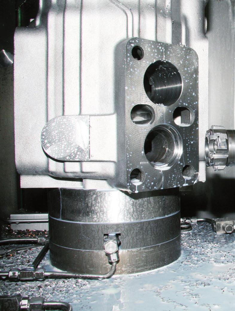
126 126

127 Tools with ISO elements Innovative complete solutions Innovative complete solutions MAPAL ISO tools unfold their possibilities particularly in the context of complete projects in which they are able to deliver significant advantages due to the combinations and high productivity. Together with tailored services and the complete tool package, MAPAL is able to optimally design parts in accordance with customer requirements and provide support. In the following the range of service offered by MAPAL and especially the significance of ISO tools are presented based on a few important parts. With the perfect tool to the optimal process 128 Brake calipers made of spheroidal graphite cast iron 130 Complete machining of turbochargers 131 Stub axle assembly made of grey cast iron or steel 132 Connecting rods made of forged steel 133 Compressor housing made of GG Gearbox housing made of GG Innovative solutions 127


128 With the perfect tool to the optimal process Due to the combination of innovative technology and absolute manufacturing precision, MAPAL ISO tools are high performance tools. However successful individual tools on their own are not sufficient for the competitive production requirements these days. Only an understanding of the complete machining process and the production process as a whole permits real progress. Advantage due to complete concepts The perfect interaction of all components in a machining process makes possible the highest possible cost-effectiveness and addresses the increasingly important aspect of resource-saving production. Here it is particularly important that comprehensive knowledge of all machining processes and machining technologies is available even during the process planning. MAPAL provides the ideal basis for the process planner with its broad range of innovative, high-performance tools and its extensive pool of experience. Advantages: Solutions for complete workpieces including all components Usage of efficient, cost-optimised tools Complete, cost-effective manufacturing process Process planning and implementation from a single source For this purpose, use is made of all tool technologies as necessary, from the highperformance solid carbide drill to the sophisticated mechatronic TOOLTRONIC tool. MAPAL ISO tools have particular significance during pre-machining and during milling. The results are machining solutions without compromises. Hybrid tools as process optimisers An important possible way of optimising processes, increasing productivity and productivity is to combine various machining technologies. So-called hybrid tools combine various machining systems in a manner that combines excellent performance with straightforward handling and cost-effective reconditioning. The specialists from MAPAL combine, in numerous ways, ISO tools with guide pad technology, with fixed brazed PCD machining stages, with solid carbide tools or with fixed tool technology. In this way maximum productivity and cost-effectiveness is achieved both in the process design and the tool design. 128


129 Tools with ISO elements Innovative complete solutions MAPAL Services offer numerous options Shorter product life cycles and increasing pressure on productivity are requiring ever better performance from the global manufacturing industry. Even the planning phase is very time-consuming and devours expensive resources. At the same time project and planning departments must react flexibly to the current order situation. To support customers with these challenges, MAPAL offers a comprehensive package of services. These services range from the definition of the correct machining strategy with efficient tools through the design of clamping fixtures to the preparation of NC programs and commissioning machining processes. Ongoing manufacturing is supported in the area of logistics, reconditioning and training. In this way MAPAL helps to keep manufacturing highly productive, cost-effective and reliable. The customer receives the complete process from a single source and gains capacity to strengthen the core business. Engineering MAPAL TET Planning of complete workpieces including all tools MAPAL re.tooling Planning of complete workpieces including all components and commissioning Logistics MAPAL TMS Tool management MAPAL TLS Logistics and stock management MAPAL Toolbase Tool dispensing systems Maintenance MAPAL re.conditioning Regrinding and reconditioning of tools, milling cartridges and indexable inserts MAPAL training Product and technology seminars MAPAL TOS Tool and process optimisation Innovative solutions 129

130 Tools with ISO elements Innovative complete solutions Brake calipers made of spheroidal graphite cast iron Potential for savings due to the latest manufacturing technology The quality of the manufacture of this safety-related part defines the braking forces via braking performance, stability under load and exact control. The MAPAL tool package for machining the brake caliper guarantees reliable manufacture with low manufacturing costs per unit. These advantages are provided, for example, by combination tools with which it is possible to drill, mill and deburr at various positions. In total up to 40 % of machining time can be saved using the MAPAL process. Tool highlights on the brake caliper 1. Control cut for the fist hole, premachining of the front area for the piston, pilot bore for the piston bore The combination of several machining steps reduces the cycle time and increases the machining quality. 2. Interpolation recessing of sealing ring groove and base profile The MAPAL tool reduces the machining time by 50 % compared to circular milling and improves the surface quality. 3. Fine machining of the piston bore The higher feed rate reduces the machining time by approx. 30 %. There is no setting effort, as re-grinding is possible the tool costs are reduced. 4. Fine machining of the rear of the brake housing A MAPAL actuating tool for machining centres combines diameter turning, chamfering and external grooving. In comparison to the previous process, the machining time is reduced by 12.5 seconds per workpiece. Advantages: Increased process reliability Reduction in the manufacturing costs per unit due to reduced machining times Cost guarantee due to cost per part Competent planning and reliable supply of tools with MAPAL complete process management

131 Tools with ISO elements Innovative complete solutions Complete machining of turbochargers MAPAL with leading tool technology Downsizing and turbochargers are technologies that are now indispensable in modern engine development. In the past machining centres and lathes were often necessary for the production of the turbine and compressor housing for turbochargers. MAPAL has developed a manufacturing method that makes complete machining possible on one machine. Contours and recesses are machined using the mechatronic tool system TOOLTRONIC and interpolation turning on machining centres. Complete machining tools also combine machining steps. Tool highlights for turbocharger housing 1. TOOLTRONIC for machining the contour MAPAL TOOLTRONIC, the interchangeable U axis, machines the inner contour, the diameter and various face surfaces. 2. Interpolation turning of recesses The cycle time is reduced by 35 % compared to milling. It is possible to improve the tool life due to a continuous cut and the shorter cutting time. 3. ISO tangential tool for complete machining One tool reliably, cost-effectively and precisely machines six machined features. Advantages: Machining of the main bore in the turbine housing in only four steps TOOLTRONIC replaces of the lathe Combination of a large number of machining steps due to tangential technology Innovative machining method for all machining tasks on parts for turbochargers 1 Innovative solutions


132 Tools with ISO elements Innovative complete solutions Stub axle assembly made of grey cast iron or steel Tangential technology for fast machining and low unit costs Stub axle assemblies must withstand high loads. High tolerances on shape and position must be achieved during the manufacture of the part, predominantly manufactured from grey cast iron and less frequently from steel. Despite the demanding machining, low costs are still required, as this is a mass produced part. By using multifunctional combination tools from MAPAL, tools and magazine stations are saved and therefore machining time and costs significantly reduced. Particularly advantageous for complete machining is the use of tangential indexable inserts. These inserts have a soft cut due to their positive rake angle and, due to the compact mounting, are very suitable for use on multi-insert tools with high feed rates. Tool highlights for stub axle assembly machining 1. Milling and drilling shock absorber mounting A combination of a disc milling cutter and insertion drill reduces the number of tool changes. 2. Main bore, internal machining Using the multi-stage tangential combination tool, semi-machining is saved. 3. Main bore, external machining The multi-stage combination tool with fixed insert pockets without preadjustment manufactures tolerances of less than ±0.1 mm. 4. External machining of kingpim Pre-machining, semi-machining and fine machining from one source permits the highest accuracies with the lowest scrap rate. Advantages: Process suitable for standard machines and custom machines Complete machining with minimum number of tools Rapid payback of the tool costs MAPAL service competence, also during the re-tooling of existing machines

133 Tools with ISO elements Innovative complete solutions Connecting rods made forged steel Stable, reliable process for machining lightweight connecting rods Connecting rods are engine parts subjected to high dynamic loads. Current trends in engine manufacture, for instance downsizing or the reduction of the CO 2 emissions with the same or even higher engine power output, also require new approaches during the development and manufacture of connecting rods. By using higher strength, innovative materials as well as new manufacturing processes, today it is possible to manufacture ever lighter connecting rods. In particular for the latest lightweight connecting rods MAPAL offers tool solutions for complete bore machining that reliably and cost-effectively meet all the requirements placed. To machine special part geometries, for instance the blind hole in the trapezoid form on the gudgeon pin bore, MAPAL has developed a hybrid tool that combines the advantages of ISO indexable inserts and MAPAL guide pad technology. In this way the blind hole is reliably produced in IT7 quality. Tool highlights for connecting rod machining Advantages: Stable and reliable process Combination tools reduce tool changes 1. Drilling from the solid and chamfering the small pin bore Solid drilling tool of reinforced design for heavily interrupted cuts. Additional chamfer machining in bore entrance and exit. 2. Hybrid tool for fine machining the blind hole at the small pin bore Combination of ISO indexable inserts and guide pad technology machines the trapezoid shape in IT7 quality. 3. Combination tool for small and large pin bore Combination tool with solid drilling, boring and chamfering stage for machining the small and large pin bore with minimal tool changes. 4. Solid carbide step drill for screw holes The tool combines the two bore diameters in the connecting rod and cap as well as the chamfer machining Innovative solutions 4 133

134 Tools with ISO elements Innovative complete solutions Compressor housing made of GG25 Machining a compressor housing precisely and quickly using ISO tangential tools For pre-machining and fine machining the housing and bearing cover for screw-type compressors, MAPAL offers tool solutions that are perfectly designed for the characteristic machining requirements of the compressor housing and for high efficiency. In particular the overlapping bores for the rotors for the main and secondary rotors with the related bearing bores in the compressor housing and bearing cover on the front face place high requirements on the machining tools. The reason the requirements are high is the very close geometric tolerances that are necessary for exact positioning of the spiral-shaped toothed rotors. The overlapping diameters result in a heavily interrupted cut that normally has a negative effect on the machining quality and tool life. However, this problem does not arise with the ISO combination tools used that, with their tangentially arranged indexable inserts, ensure particularly quiet tool running during the entire machining process, despite the large interruptions in the cuts. Tool highlights for machining compressor housings Advantages: Short machining times Reduced tool demand due to combination tools High positioning accuracy due to tangential technology 1. Combination tools with tangential technology Pre-machining of the rotor bores for main and secondary rotors as well as the related bores for the bearing seats. Despite the interrupted cuts the tools achieve very high positioning accuracy. 2. Fine machining of bearing seat for secondary rotor and through-bore Two-stage guide pad tool combines the fine machining of both bearing bores

135 Tools with ISO elements Innovative complete solutions Gearbox housing made of GG25 Complete solution reduces machine demand Gearbox housings mostly have very specific, complex shapes and as a rule comprise of cast materials. Depending on the nature and task of the gearbox, it may be of single or multiple shell design. During manufacture it is challenging to achieve the related fits as well as the shape and position tolerances. Due to the innovative, multifunctional tangential tools the shortest cycle times are achieved and several machining tasks are combined into one machining step. This process creates an optimal basis for the best possible availability of the machining centres. In addition the combination solutions are designed taking into account the part families a further advantage for the usage of magazine stations. The number of tools is drastically reduced. Tool highlights for machining gearbox housings 1. Combined boring tool This tool combination comprising of solid carbide drill, ISO tangential technology and ISO cartridges saves non-productive times, increases the cost-effectiveness and ensures optimal productivity. 2. Multi-stage interpolation turning tool The advantage of interpolation turning compared to circular milling is, along with the shorter cycle time and the longer tool life, in the qualitative features such as circularity and surface finish. 4. Shoulder milling cutter with tangential technology The standard shoulder milling cutter ICM90-C4-Finishing offers, with its adjusting elements, the possibility of mounting optional wide face indexable inserts and in this way achieves the quality of a pure finishing milling cutter. 1 Advantages: Reliable process Everything from a single source Productivity increase due to technologically leading tool solutions Low investment costs due to reduced machine demand 2 3. Fine boring tool with guide pads The precise fine adjustment of the guide pad tool guarantees reliable component manufacture and offers the highest degree of accuracy and with it the basis for a long part service life. 3 Innovative solutions 4 135


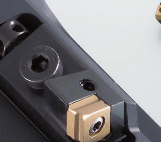

136 136


137 Tools with ISO elements Cartridges Cartridges Along with the adjusting feature with a long adjustment travel, cartridges offer interesting possibilities for many applications as they can be interchanged quickly and straightforwardly. Cartridges are used for both internal and external machining tasks. In case of changes, for example, to chamfer angles, or in case of repair, cartridges can be interchanged without major effort. The range of MAPAL cartridges covers a large part of the installation design variants. Along with the standardised ISO cartridges, a series of compact cartridges for radial and tangential indexable inserts are available. Due to short lengths these offer even more design opportunities during the design of custom tools. Designation key 138 ISO cartridges 140 Compact cartridges 144 Compact cartridges for tangential indexable inserts 150 Size comparison MAPAL compact cartridges against ISO cartridges Example: Indexable insert size Compact cartridges On request MAPAL also supplies cartridges and compact cartridges in custom designs. ISO cartridges Cartridges 137
138 Tools with ISO elements Cartridges Model key Model key cartridges and compact cartridges S T F C R Indexable insert fastening Blade form Tool holder shape Clearance angle Cutting direction S Screwed in place using countersunk bore C (80 ) S (90 ) F (90 ) G (90 ) J (93 ) A A K T K K T T A A K A N 0 R Right T (60 ) W (80 ) K (75 ) L (95 ) R (75 ) S (45 ) A T A K A K T K T K A A K T K T K C 7 P 11 D 15 E 20 Left L F (70 ) W (60 ) T (60 ) Y (85 ) A K T See features K T K T K A A K T K T K A K C S T W F A = Cartridges K = Compact cartridges T = Compact cartridges for tangential indexable inserts Compact cartridges with custom angle Data on the tool holder shape directly via the setting angle 70 z. B. ST70CR 08CK z.b. SW80NR 18CT
139 Tools with ISO elements Cartridges Model key 0 8 C A Tool holder height Features Insert size Height data Code (mm) 06 6,0 1. digit Significance C A Cartridges 2. digit Significance Cartridge in accordance with DIN 4985 Incircle d d d d d l l l l l d (mm) C S T W F 5, , , , , , , ,0 K Compact cartridge similar to DIN , ,0 T Compact cartridge similar to DIN 4985 for tangential indexable inserts 18 18,0 Cartridges 139
140 Tools with ISO elements Cartridges ISO cartridges Form F, G SCG l 3 l 1 90 d 1 min. h 1 t e SCF l 1 STF l 1 STG l 1 l 3 l 3 l f f 90 f f h 2 e e e Shown as right hand version SCFCR. Dimensions Specification Related insert (referred to R-Nom) h 1 f R-Nom l 1 e l 3 h 2 t d 1 min. Accessory group STG SCG STF SCF SCFCR 08 CA-06 CC , ,5 4, SCFCL 08 CA-06 CC , ,5 4, SCFPR 08 CA-06 CP , ,5 4, SCFPL 08 CA-06 CP , ,5 4, SCFCR 10 CA-09 CC 09T , SCFCL 10 CA-09 CC 09T , SCFCR 12 CA-12 CC , SCFCL12 CA-12 CC , STFCR 08 CA-09 TC , ,5 4, STFCL 08 CA-09 TC , ,5 4, STFCR 10 CA-11 TC , STFCL 10 CA-11 TC , STFCR 12 CA-16 TC 16T , STFCL 12 CA-16 TC 16T , SCGCR 08 CA-06 CC , ,5 4, SCGCL 08 CA-06 CC , ,5 4, SCGPR 08 CA-06 CP , ,5 4, SCGPL 08 CA-06 CP , ,5 4, SCGCR 10 CA-09 CC 09T , SCGCL 10 CA-09 CC 09T , SCGCR 12 CA-12 CC , SCGCL 12 CA-12 CC , STGCR 08 CA-09 TC , ,5 4, STGCL 08 CA-09 TC , ,5 4, STGCR 10 CA-11 TC , STGCL 10 CA-11 TC , STGCR 12 CA-16 TC 16T , STGCL 12 CA-16 TC 16T , Supply includes: Cartridge with mounted components. Indexable insert and accessories please order separate. Dimensions in mm. 140
141 Tools with ISO elements Cartridges ISO cartridges Form J, K, L d 1 min. SSK h l 1 1 STJ SCL l 1 l 2 l1 t l 3 l 3 l 3 93 f f f h 2 e e e Shown as right hand version STJCR. Dimensions Specification Related insert (referred to R-Nom) h 1 f R-Nom l 1 l 2 e l 3 h 2 t d 1 min. Accessory group STJ SSK SCL STJCR 08 CA-09 TC , ,5 4, STJCL 08 CA-09 TC , ,5 4, STJCR 10 CA-11 TC , STJCL 10 CA-11 TC , STJCR 12 CA-16 TC 16T , STJCL 12 CA-16 TC 16T , SSKCR 08 CA-06 SC ,4 33, ,5 4, SSKCL 08 CA-06 SC ,4 33, ,5 4, SSKCR 10 CA-09 SC 09T ,8 52, SSKCL 10 CA-09 SC 09T ,8 52, SSKCR 12 CA-12 SC ,8 58, SSKCL 12 CA-12 SC ,8 58, SCLCR 08 CA-06 CC , ,5 4, SCLCL 08 CA-06 CC , ,5 4, SCLPR 08 CA-06 CP , ,5 4, SCLPL 08 CA-06 CP , ,5 4, SCLCR 10 CA-09 CC 09T , SCLCL 10 CA-09 CC 09T , SCLCR 12 CA-12 CC , SCLCL 12 CA-12 CC , Cartridges Supply includes: Cartridge with mounted components. Indexable insert and accessories please order separate. Dimensions in mm. 141
142 Tools with ISO elements Cartridges ISO cartridges Form R, S d 1 min. h 1 SSR SSS STS l 1 l 1 l 1 l 2 l 2 l 2 75 l 3 l 3 l 3 t f 45 f 45 f h 2 e e e Shown as right hand version SSRCR. Dimensions Specification Related insert (referred to R-Nom) h 1 f R-Nom l 1 l 2 e l 3 h 2 t d 1 min. Accessory group SSR SSS STS SSRCR 08 CA-06 SC , , ,5 4, SSRCL 08 CA-06 SC , , ,5 4, SSRCR 10 CA-09 SC 09T , , SSRCL 10 CA-09 SC 09T , , SSRCR 12 CA-12 SC , , SSRCL 12 CA-12 SC , , SSSCR 08 CA-06 SC ,4 32, ,5 4, SSSCL 08 CA-06 SC ,4 32, ,5 4, SSSCR 10 CA-09 SC 09T ,8 50, SSSCL 10 CA-09 SC 09T ,8 50, SSSCR 12 CA-12 SC ,8 55, SSSCL 12 CA-12 SC ,8 55, STSCR 08 CA-09 TC ,4 34, ,5 4, STSCL 08 CA-09 TC ,4 34, ,5 4, STSCR 10 CA-11 TC , STSCL 10 CA-11 TC , STSCR 12 CA-16 TC 16T ,8 57, STSCL 12 CA-16 TC 16T ,8 57, Supply includes: Cartridge with mounted components. Indexable insert and accessories please order separate. Dimensions in mm. 142
143 Tools with ISO elements Cartridges ISO cartridges Form T, Y d 1 min. h 1 SST l 1 STT l 1 SSY l 2 l 2 l l 3 l 3 l 2 l1 t f f 85 f h 2 e e e Shown as right hand version SSTCR. Dimensions Specification Related insert (referred to R-Nom) h 1 f R-Nom l 1 l 2 e l 3 h 2 t d 1 min. Accessory group SST STT SSY SSTCR 08 CA-06 SC , , ,5 4, SSTCL 08 CA-06 SC , , ,5 4, SSTCR 10 CA-09 SC 09T ,3 0, , SSTCL 10 CA-09 SC 09T ,3 0, , SSTCR 12 CA-12 SC ,9 0, , SSTCL 12 CA-12 SC ,9 0, , STTCR 08 CA-09 TC ,3 0, , ,5 4, STTCL 08 CA-09 TC ,3 0, , ,5 4, STTCR 10 CA-11 TC , , STTCL 10 CA-11 TC , , STTCR 12 CA-16 TC 16T ,2 0, , STTCL 12 CA-16 TC 16T ,2 0, , SSYCR 08 CA-06 SC ,4 32, ,5 4, SSYCL 08 CA-06 SC ,4 32, ,5 4, SSYCR 10 CA-09 SC 09T ,8 50, SSYCL 10 CA-09 SC 09T ,8 50, SSYCR 12 CA-12 SC , SSYCL 12 CA-12 SC , Cartridges Supply includes: Cartridge with mounted components. Indexable insert and accessories please order separate. Dimensions in mm. 143
144 Tools with ISO elements Cartridges Compact cartridges Compact cartridges Form F d 1 min. h 1 SCF l 1 SSF l 1 STF l 1 l 3 l 3 l 3 t f f f h 2 e e e Shown as right hand version SCFCR. Dimensions Specification Related insert (referred to R-Nom) h 1 f R-Nom l 1 e l 3 h 2 t d 1 min. Accessory group SCF SSF STF SCFCR 06 CK-06V1 CC ,5 0, ,0 2, SCFCL 06 CK-06V1 CC ,5 0, ,0 2, SCFCR 06 CK-06V2 CC ,7 0, ,0 2, SCFCL 06 CK-06V2 CC ,7 0, ,0 2, SCFCR 10 CK-09 CC 09T , SCFCL 10 CK-09 CC 09T , SCFCR 12 CK-12 CC , SCFCL 12 CK-12 CC , SSFPR 08 CK-06 SP , , SSFPL 08 CK-06 SP , , SSFCR 10 CK-09 SC 09T , SSFCL 10 CK-09 SC 09T , SSFCR 12 CK-12 SC , SSFCL 12 CK-12 SC , STFCR 06 CK-09 TC , , STFCL 06 CK-09 TC , , STFCR 10 CK-11 TC , STFCL 10 CK-11 TC , STFCR 12 CK-16 TC 16T , STFCL 12 CK-16 TC 16T , Supply includes: Cartridge with mounted components. Indexable insert and accessories please order separate. Dimensions in mm. 144
145 Tools with ISO elements Cartridges Compact cartridges Compact cartridges Form G, L d 1 min. h 1 SCG l SCL 1 l 1 l 3 90 l 3 95 t f 95 f h 2 e e Shown as right hand version SCGCR. Dimensions Specification Related insert (referred to R-Nom) h 1 f R-Nom l 1 e l 3 h 2 t d 1 min. Accessory group SCG SCL SCGCR 06 CK-06V1 CC ,5 0, , SCGCL 06 CK-06V1 CC ,5 0, , SCGCR 06 CK-06V2 CC ,7 0, , SCGCL 06 CK-06V2 CC ,7 0, , SCGCR 10 CK-09 CC 09T , SCGCL 10 CK-09 CC 09T , SCGCR 12 CK-12 CC , SCGCL 12 CK-12 CC , SCLCR 06 CK-06V1 CC ,5 0, ,0 2, SCLCL 06 CK-06V1 CC ,5 0, ,0 2, SCLCR 06 CK-06V2 CC ,7 0, ,0 2, SCLCL 06 CK-06V2 CC ,7 0, ,0 2, SCLCR 10 CK-09 CC 09T , , SCLCL 10 CK-09 CC 09T , , SCLCR 12 CK-12 CC , , SCLCL 12 CK-12 CC , , Cartridges Supply includes: Cartridge with mounted components. Indexable insert and accessories please order separate. Dimensions in mm. 145
146 Tools with ISO elements Cartridges Compact cartridges l 1 STR l 2 Compact cartridges Form R l3 75 f d 1 min. SCR V1 SCR V2 SSR e h1 l2 l1 l 1 l2 l 2 l 1 l 3 l 3 l t f f f h 2 e e e Shown as right hand version SCRCR. Dimensions Specification Related insert (referred to R-Nom) h 1 f R-Nom l 1 l 2 e l 3 h 2 t d 1 min. Accessory group STR SSR SCR V2 SCR V1 SCRCR 06 CK-06 V1 CC ,7 0, , , SCRCL 06 CK-06 V1 CC ,7 0, , , SCRCR 10 CK-09 V1 CC 09T , , SCRCL 10 CK-09 V1 CC 09T , , SCRCR 06 CK-06 V2 CC , , , SCRCL 06 CK-06 V2 CC , , , SCRCR 10 CK-09 V2 CC 09T , , SCRCL 10 CK-09 V2 CC 09T , , SSRPR 08 CK-06 SP , , , SSRPL 08 CK-06 SP , , , SSRCR 10 CK-09 SC 09T , , SSRCL 10 CK-09 SC 09T , , SSRCR 12 CK-12 SC , , SSRCL 12 CK-12 SC , , STRCR 06 CK-09 TC , , , STRCL 06 CK-09 TC , , , STRCR 10 CK-11 TC , , STRCL 10 CK-11 TC , , STRCR 12 CK-16 TC 16T , , STRCL 12 CK-16 TC 16T , , Supply includes: Cartridge with mounted components. Indexable insert and accessories please order separate. Dimensions in mm. 146
147 Tools with ISO elements Cartridges Compact cartridges Compact cartridges Form S d1 min. h 1 t SCS V1 SCS V2 SSS l 1 l 1 l 2 f l 2 l 3 l 3 l f STS l 3 e l 1 l2 l 1 l 2 45 f f h 2 e e e Shown as right hand version SCSCR. Dimensions Specification Related insert (referred to R-Nom) h 1 f R-Nom l 1 l 2 e l 3 h 2 t d 1 min. Accessory group STS SSS SCS V2 SCS V1 SCSCR 06 CK-06 V1 CC ,7 0, , , SCSCL 06 CK-06 V1 CC ,7 0, , , SCSCR 10 CK-09 V1 CC 09T , , SCSCL 10 CK-09 V1 CC 09T , , SCSCR 06 CK-06 V2 CC , , , SCSCL 06 CK-06 V2 CC , , , SCSCR 10 CK-09 V2 CC 09T ,3 0, , SCSCL 10 CK-09 V2 CC 09T ,3 0, , SSSPR 08 CK-06 SP , , , SSSPL 08 CK-06 SP , , , SSSCR 10 CK-09 SC 09T , , SSSCL 10 CK-09 SC 09T , , SSSCR 12 CK-12 SC , , SSSCL 12 CK-12 SC , , STSCR 06 CK-09 TC , , , STSCL 06 CK-09 TC , , , STSCR 10 CK-11 TC , STSCL 10 CK-11 TC , STSCR 12 CK-16 TC 16T , , STSCL 12 CK-16 TC 16T , , Cartridges Supply includes: Cartridge with mounted components. Indexable insert and accessories please order separate. Dimensions in mm. 147
148 Tools with ISO elements Cartridges Compact cartridges STT l2 l1 Compact cartridges Form T d1 min. h 1 t SCT V1 SCT V2 SST l 1 l 1 l 2 f l 2 l 2 l3 l3 l f l3 e l f f h 2 e e e Shown as right hand version SCTCR. Dimensions Specification Related insert (referred to R-Nom) h 1 f R-Nom l 1 l 2 e l 3 h 2 t d 1 min. Accessory group STT SST SCT V2 SCT V1 SCTCR 06 CK-06 V1 CC ,7 0, , , SCTCL 06 CK-06 V1 CC ,7 0, , , SCTCR 10 CK-09 V1 CC 09T , , SCTCL 10 CK-09 V1 CC 09T , , SCTCR 06 CK-06 V2 CC , , , SCTCL 06 CK-06 V2 CC , , , SCTCR 10 CK-09 V2 CC 09T , , SCTCL 10 CK-09 V2 CC 09T , , SSTPR 08 CK-06 SP , , , SSTPL 08 CK-06 SP , , , SSTCR 10 CK-09 SC 09T , , SSTCL 10 CK-09 SC 09T , , SSTCR 12 CK-12 SC , , SSTCL 12 CK-12 SC , , STTCR 06 CK-09 TC , , , STTCL 06 CK-09 TC , , , STTCR 10 CK-11 TC , , STTCL 10 CK-11 TC , , STTCR 12 CK-16 TC 16T , , STTCL 12 CK-16 TC 16T , , Supply includes: Cartridge with mounted components. Indexable insert and accessories please order separate. Dimensions in mm. 148
149 Tools with ISO elements Cartridges Compact cartridges SSY l 1 l 1 l 2 STW l 2 Compact cartridges Form W, Y l 3 l f f d 1 min. h 1 SCW V1 l1 l 2 SCW V2 e e l 1 l 1 SSW l2 l 2 l 3 l 3 l t f f f h 2 e e e Shown as right hand version SCWCR. Dimensions Specification Related insert (referred to R-Nom) h 1 f R-Nom l 1 l 2 e l 3 h 2 t d 1 min. Accessory group SSY STW SSW SCW V2 SCW V1 SCWCR 06 CK-06 V1 CC ,7 0, , SCWCL 06 CK-06 V1 CC ,7 0, , SCWCR 10 CK-09 V1 CC 09T , , SCWCL 10 CK-09 V1 CC 09T , , SCWCR 06 CK-06 V2 CC , , SCWCL 06 CK-06 V2 CC , , SCWCR 10 CK-09 V2 CC 09T ,3 0, , SCWCL 10 CK-09 V2 CC 09T ,3 0, , SSWPR 08 CK-06 SP , , , SSWPL 08 CK-06 SP , , , SSWCR 10 CK-09 SC 09T , , SSWCL 10 CK-09 SC 09T , , SSWCR 12 CK-12 SC , , SSWCL 12 CK-12 SC , , STWCR 06 CK-09 TC , , , STWCL 06 CK-09 TC , , , STWCR 10 CK-11 TC , STWCL 10 CK-11 TC , STWCR 12 CK-16 TC 16T , , STWCL 12 CK-16 TC 16T , , SSYPR 08 CK-06 SP , , , SSYPL 08 CK-06 SP , , , SSYCR 10 CK-09 SC 09T , , SSYCL 10 CK-09 SC 09T , , SSYCR 12 CK-12 SC , SSYCL 12 CK-12 SC , Cartridges Supply includes: Cartridge with mounted components. Indexable insert and accessories please order separate. Dimensions in mm. 149
150 Tools with ISO elements Cartridges Compact cartridges for tangential indexable inserts Compact cartridges for tangential indexable inserts Form F, K SWF SCF d 1 min. h 1 h 2 d 1 min. h 1 t SWF SCF l 3 l 3 e l 1 l 1 90 f SCK SFF l 3 l 3 e l 1 l 2 l 1 75 f f f h 2 t e e Shown as right hand version SCFNR. Dimensions Specification Related insert (referred to R-Nom) h 1 f R-Nom l 1 I 2 e l 3 h 2 t d 1 min. Accessory group SCK SFF SWF SCF SCFNR 10 CT-06 CTHQ , , SCFNR 14 CT-09 CTHQ , SCFNR 18 CT-12 CTHQ , SCFDR 10 CT-06 CTHD , , SCFNR 14 CT-09 CTHD09T , l SCFNR 18 CT-12 CTHD , l 3 SWFNR 14 CT-07 WTHQ , SWFNR 18 CT-09 WTHQ , , SFFNR 10 CT-06 FTHQ , , SFFNR 14 CT-09 FTHQ , SFFNR 18 CT-12 FTHQ , ,5 e SCKNR 10 CT-06 CTHQ , , , SCKNR 14 CT-09 CTHQ ,8 42,5 40, SCKDR 10 CT-06 CTHD , , , SCKDR 14 CT-09 CTHD ,8 42,5 40, f Supply includes: Cartridge with mounted components. Indexable insert and accessories please order separate. Dimensions in mm. 150
151 Tools with ISO elements Cartridges Compact cartridges for tangential indexable inserts SCW l1 l2 Compact cartridges for tangential indexable inserts Form 80, W l3 60 f e SC80 d 1 min. h1 SC80 l1 SW80 l 1 SF80 l1 l3 80 f l 3 80 f l3 80 f h 2 t e e e Shown as right hand version SC80NR. Dimensions Specification Related insert (referred to R-Nom) h 1 f R-Nom l 1 l 2 e l 3 h 2 t d 1 min. Accessory group SCW SF80 SW80 SC80 SC80NR 10 CT-06 CTHQ , , SC80NR 14 CT-09 CTHQ , SC80NR 18 CT-12 CTHQ , SC80DR 10 CT-06 CTHD , , SC80DR 10 CT-09 CTHD , SC80DR 10 CT-12 CTHD , SW80NR 14 CT-07 WTHQ , SW80NR 18 CT-09 WTHQ , , SF80NR 10 CT-06 FTHQ , , SF80NR 14 CT-09 FTHQ , SF80NR 18 CT-12 FTHQ , , SCWNR 10 CT-06 CTHQ , , , SCWNR 10 CT-09 CTHQ ,8 42, SCWDR 10 CT-06 CTHD , , , SCWDR 10 CT-06 CTHD ,8 42, Cartridges Supply includes: Cartridge with mounted components. Indexable insert and accessories please order separate. Dimensions in mm. 151
152 Tools with ISO elements Cartridges Compact cartridges for tangential indexable inserts Compact cartridges for tangential indexable inserts Form S, T, R SCS SCS SCT SCR d 1 min. h 1 l l 1 1 l l 2 2 l 2 l 1 l 3 l 3 60 l t f f f h 2 Shown as right hand version SCSNR. e e Dimensions e Specification Related insert (referred to R-Nom) h 1 f R-Nom l 1 I 2 e l 3 h 2 t d 1 min. Accessory group SCS SCT SCR SCSNR 10 CT-06 CTHQ ,8 30,0 25, , SCSNR 14 CT-09 CTHQ ,8 42, SCSDR 10 CT-06 CTHD , , , SCSDR 14 CT-09 CTHD ,8 42, SCTNR 10 CT-06 CTHQ , , , SCTNR 14 CT-09 CTHQ ,8 42,5 34, SCTDR 10 CT-06 CTHD , , , SCTDR 14 CT-09 CTHD ,8 42,5 34, SCRNR 10 CT-06 CTHQ , , SCRNR 14 CT-09 CTHQ ,8 42,5 33, SCRDR 10 CT-06 CTHD , , SCRDR 14 CT-09 CTHD ,8 42,5 33, Supply includes: Cartridge with mounted components. Indexable insert and accessories please order separate. Dimensions in mm. 152
153 f f f f Tools with ISO elements Cartridges Compact cartridges for tangential indexable inserts SSS l1 SST l 1 Compact cartridges for tangential indexable inserts Form W, S, T, 20, R SSW SSW SSR SS20 d 1 min. l 1 l1 l 3 e l 2 45 f l3 e l2 l 1 60 h 1 l2 l2 l2 l 3 l 3 75 l h2 t e e e Shown as right hand version SSWDR. Dimensions Specification Related insert (referred to R-Nom) h 1 f l 1 I 2 e l 3 h 2 t d 1 min. Accessory group SSR SS20 SST SSS SSW SSWDR 08 CT-06 STHD0603 8,5 9 23,5 20,3 11,5 5 8,2 3, SSWDR 14 CT-09 STHD09T ,5 35, , SSSDR 08 CT-06 STHD0603 8,5 9 23, ,5 5 8,2 3, SSSDR 14 CT-09 STHD09T ,5 35, , SSTDR 08 CT-06 STHD0603 8, ,5 11,5 5 8,2 3, SSTDR 14 CT-09 STHD09T , , , SS20DR 08 CT-06 STHD0603 8, ,5 5 8,2 3, SS20DR 14 CT-09 STHD09T , , SSRDR 08 CT-06 STHD0603 8, ,9 11,5 5 8,2 3, SSRDR 14 CT-09 STHD09T , , , Cartridges Supply includes: Cartridge with mounted components. Indexable insert and accessories please order separate. Dimensions in mm. 153
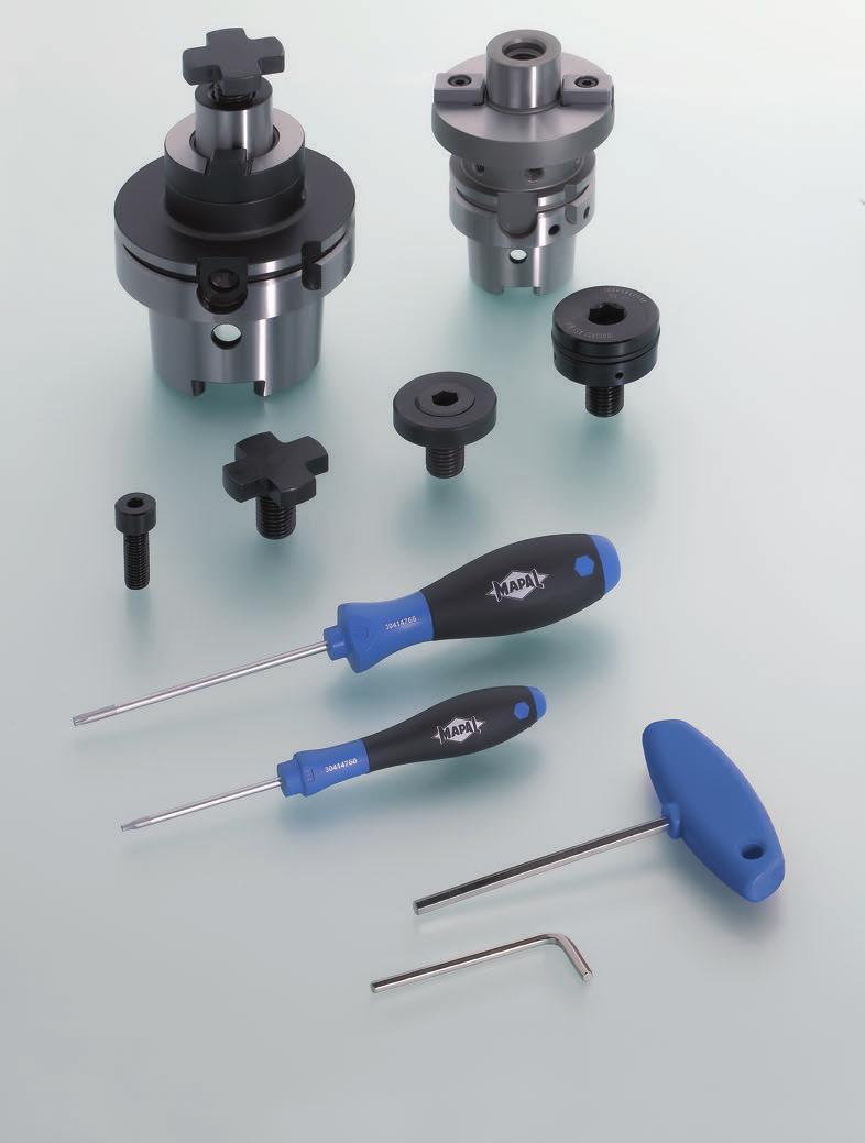
154 154

155 Tools with ISO elements Accessories and spare parts Accessories and spare parts The broad range of MAPAL tools with ISO elements is supplemented with all essential additional parts and spare parts. Here the focus is on the parts that are necessary for the correct usage of the tools with ISO elements. However, the section also contains tools such as torque wrench sets and screwdrivers. Tangential roughing tools TSW 156 Tangential fine boring tools TFB 157 Assignment milling cutter adapter milling cutter clamping screw 158 Milling cutters general 160 Milling cutter arbors 162 Indexable inserts 166 Cartridges and compact cartridges 168 Screwdriver 170 Accessories Spare parts 155

156 d* M d k l 1 l 2 wrench l b t d 1 d 2 l 1 Clamping screw TSV ISO M ,0 10,0 9,5 7,5 4, M dk b d2 d1 M dk t Tools with ISO elements Accessories and spare parts Tangential roughing tools TSW Accessories and spare parts tangential roughing tools TSW Key block Fastening screw for key block Clamping screw for indexable insert Clamping screw d1 l1 b sw l1 l2 d2 l Clamping screw Key block Dimensions Comments Dimensions size (sw) sw l1 l2 Clamping screw TSV ISO M ** 40 M ** M dk l 13,0 10,0 11,2 8,0 4, ,9 12,0 12,6 8,0 4, ,0 16,0 16,0 10,0 5, ,5 25,4 25,0 19,0 13, l1 l1 l2 Clamping screw DIN M M dk α dk M sw l1 l2 TORX PLUS l1 Clamping screw for indexable insert (TORX PLUS ) Fastening screw for key block ISO 4762 Indexable insert size Dimensions Dimensions d k M l 1 TX α M d k l 1 l ,7 M IP ,8 M IP wrench size (sw) M4 7,0 10,0 4, M4 7,0 16,0 4, M5 8,5 16,0 5, M12 18,0 25,0 12, ** See page 196 for handling notes. Dimensions in mm. d* = Diameter of arbor 156
 Adjusting wedge Indexable insert size Dimensions Dimensions Comments d k M l 1 TX α M d l 0905 4,8 M3,5 11")
157 Tools with ISO elements Accessories and spare parts Tangential fine boring tools TFB Accessories and spare parts tangential fine boring tools TFB Clamping screw for indexable insert Threaded spindle Adjusting wedge l M d α dk M TORX PLUS l1 Clamping screw for indexable insert (TORX PLUS ) Adjusting wedge Indexable insert size Dimensions Dimensions Comments d k M l 1 TX α M d l ,8 M3, IP M5x0,5 6,8 7 M5x0,5 LH K l M 1 M 2 sw l 1 l 2 Threaded spindle Dimensions M 1 l l 1 M 2 l 2 wrench size (sw) M5x0,5LH 13 5,5 M5x0,5 5,5 2, Spare parts for intermediate adapters Module diameter D Quantity required Cylinder head screw in accordance with ISO 4762 Thrust pad Threaded pin Size Specification Specification 80 4 M6x K K M8x K K M8x K K M10x K K Spare parts for machine adapters For module diameter D Quantity required Threaded pin Size Specification M8x1x16 K M10x1x20 K Accessories Spare parts 157
158 Tools with ISO elements Accessories and spare parts Assignment milling cutter adapter milling cutter clamping screw Assignment milling cutter adapter milling cutter clamping screw IFM75 ICM90-S4 MCA-HSK- Adapters MCA-SK- MCA-HSK- Adapters MCA-SK- Page 162 Page 164 Page 162 Page 164 Milling cutter clamping screw Milling cutter arbor ø * ø ** ø ** ø ** Without IC With IC Without IC With IC ø ø ø ** ø ** ø ** ø ICM90 ICM90-B2 MCA-HSK- Adapters MCA-SK- MCA-HSK- Adapters MCA-SK- Page 162 Page 164 Page 162 Page 164 Milling cutter clamping screw Milling cutter clamping screw Milling cutter arbor Milling cutter arbor Without IC With IC ø * ø ** ø ** ø ** * Supply includes. ** See page 196 for handling notes. Without IC With IC ø * ø * ø * ø * 158

159 Tools with ISO elements Accessories and spare parts Assignment milling cutter adapter milling cutter clamping screw ICM90-2BM IDM88/90 MCA-HSK- Adapters MCA-SK- MCA-HSK- Adapters MCA-SK- Page 162 Page 164 Page 162 Page 164 Milling cutter clamping screw Milling cutter clamping screw Milling cutter arbor Milling cutter arbor Without IC ø * ø * ø * ø * ø ** Without IC ø ** ø ** IHM90 Example: Clamping using a standard arbor MCA-HSK- MCA-HSK- Adapters MCA-SK- Page 162 Page 164 Milling cutter clamping screw Milling cutter arbor Without IC With IC ø ** MCA-HSK- Spacer ring IDM88/90 Milling cutter clamping screw * Supply includes. ** See page 196 for handling notes. Accessories Spare parts 159

 l M 1 M 2 sw l 1 l 2 Threaded spindle Dimensions Model Threaded bush (IDM88-L8-L/R) Dimensions Model wrench size (sw) wrench size (sw) t 1 l Adjusting wedge Dimensions Model Backing plate")
160 Tools with ISO elements Accessories and spare parts Milling Accessories milling ICM90-C2-Finishing, IDM88-L8-L/R IDM88-L8-L/R Clamping screw Threaded bush Adjusting wedge Threaded spindle Backing plate l M TORX PLUS sw l 1 M l d k M l 1 TX α M3 8 1,5 With IC M5 5 2,5 Without IC LT_U15 5,7 M IP M l M d k l 1 l 2 M 1 M4x0,5 9 2 M4x0,5 LH K M6x0, M6x0,5x12/M l M d M M 1 d k sw l 1 l 2 t d 1 d 2 b M Threaded pin Clamping screw for indexable insert (IDM88-L8-L/R) Dimensions Comments Indexable insert size Dimensions wrench size (sw) l M 1 M 2 sw l 1 l 2 Threaded spindle Dimensions Model Threaded bush (IDM88-L8-L/R) Dimensions Model wrench size (sw) wrench size (sw) t 1 l Adjusting wedge Dimensions Model Backing plate (IDM88-L8-L/R) Dimensions Comments M d l d 1 d 2 l b t t 1 Dimensions in mm. 160

161 Tools with ISO elements Accessories and spare parts Milling Coolant tube Spacer ring Milling cutter clamping screw d1 d M dk l l1 l2 Spacer ring DIN 2084-B Dimensions Comments Milling cutter clamping screws Dimensions Comments d* d 1 d l for IDM90... with WSP CT for IDM90... with WSP CT for IDM88 with WSP LT_U for IDM88 with WSP LT_U for IDM90... with WSP CT for IDM90... with WSP CT for IDM88 with WSP LT_U for IDM88 with WSP LT_U Coolant tube M d2 d1 Dimensions Comments d* d 1 d 2 M18x For HSK M24x1, For HSK d* M d k l 1 l 2 16 M M M Without IC M M sw wrench size (sw) M 16 M ** 22 M ** 27 M Without IC ** 32 M ** 40 M ** M l1 l2 dk dk M dk sw l1 l2 Milling cutter clamping screws ISO 4762 Dimensions Comments sw 22 M M , With IC 32 M , M , l1 l2 d* M d k l 1 l 2 16 M M M Without IC 27 M M M d* = Diameter of arbor ** See page 197 for handling notes. Dimensions in mm. wrench size (sw) sw M 16 M M With IC 27 M M l1 l2 dk 161 Accessories Spare parts
162 Tools with ISO elements Accessories and spare parts Milling cutter arbors Milling cutter arbors for milling cutters with longitudinal or cross slot in accordance with DIN Shank HSK-A in accordance with DIN l 4 d 1 d 2 l 3 l 1 l 2 Nominal size HSK-A Dimensions Weight kg Specification d 1 d 2 l 1 l 2 l 3 l ,9 MCA-HSK-A W ,0 MCA-HSK-A W ,4 MCA-HSK-A W ,8 MCA-HSK-A W ,4 MCA-HSK-A W ,6 MCA-HSK-A W ,0 MCA-HSK-A W ,4 MCA-HSK-A W Spare parts For arbor diameter Milling cutter clamping screw in accordance with DIN 6367 Feather key in accordance with DIN (with jacking thread) Driving ring in accordance with DIN d 1 Size Size Size 16 M x4x Gr M x6x Gr M x7x Gr M x8x Gr Supply includes: Milling cutter clamping screw, feather key with jacking thread and driving ring, does not include coolant tube. Design: Permissible run-out variation on the hollow taper shank in relation to the arbor d 1 = mm. Note: Milling adapter rings in accordance with DIN 2084 on request. For coolant tubes see page 161. Balancing quality: G 2.5 at 16,000 min -1 Dimensions in mm. 162
163 Tools with ISO elements Accessories and spare parts Milling cutter arbors Milling cutter arbors with enlarged face connection diameter in accordance with DIN Shank HSK-A in accordance with DIN d 1 d 2 l 1 l 2 Nominal size HSK-A Dimensions d 1 d 2 l 1 l 2 Weight kg Specification With milling cutter clamping screw ,1 MCA-HSK-A W ,3 MCA-HSK-A W ,4 MCA-HSK-A W * ,9 MCA-HSK-A W ,5 MCA-HSK-A W ,7 MCA-HSK-A W ,8 MCA-HSK-A W * ,8 MCA-HSK-A W * ,5 MCA-HSK-A W Spare parts For arbor diameter Milling cutter clamping screw in accordance with DIN 6367 Milling cutter clamping screw with internal coolant supply (e.g. for MAPAL PCD milling heads) Key block (2x) Fastening screw in accordance with ISO 4762 (2x) d 1 Size Specification Size 22 M MT M4x M MT M4x M MT M5x M MT M5x M MT M12x Supply includes: 1 Key blocks attached and milling cutter clamping screw in accordance with DIN Design: Permissible run-out variation on the hollow taper shank in relation to the arbor d 1 = mm. Six balancing bores on the periphery. Note: The sizes marked with * have four additional threaded bores for mounting cutter heads with tool fastening in accordance with DIN For coolant tubes see page 161. Balancing quality: G 2.5 at 16,000 min -1 Accessories Spare parts Dimensions in mm. 163
164 d 2 d 1 Tools with ISO elements Accessories and spare parts Milling cutter arbors Milling cutter arbors with enlarged face connection diameter Shank SK in accordance with DIN Form AD/B l 1 l 2 Nominal size SK Dimensions d 1 d 2 l 1 l 2 Weight kg Specification With milling cutter clamping screw 1 40** ,8 MCA-SK W ,1 MCA-SK W ,1 MCA-SK W ,7 MCA-SK W * ,9 MCA-SK W ** ,4 MCA-SK W ,1 MCA-SK W ,3 MCA-SK W ,7 MCA-SK W * ,3 MCA-SK W * ,0 MCA-SK W Spare parts For arbor diameter + Milling cutter clamping screw in accordance with DIN 6367 Key block Fastening screw in accordance with ISO 4762 d 1 Size Specification Size 22 M MT M4x M MT M4x M MT M5x M MT M5x M MT M12x Supply includes: 1 Attached key blocks and milling cutter clamping screw in accordance with DIN 6367, does not include pull stud. Bores for coolant supply in accordance with Form B sealed on delivery with threaded pins. Design: Permissible run-out variation on the taper shank in relation to the arbor diameter d 1 = mm. Dimensions in mm. Note: The sizes marked with * have four additional threaded bores for mounting cutter heads with tool fastening in accordance with DIN The sizes marked with ** are available on request. Balancing quality: G 2.5 at 16,000 min

165 Tools with ISO elements Accessories and spare parts Clamping tools Note: There is a large selection of further clamping tools in the catalogue "MAPAL competence clamping technology" Accessories Spare parts 165
166 Tools with ISO elements Accessories and spare parts Radial indexable inserts Accessories for radial indexable inserts M Torx size l 1 Indexable insert Indexable insert size Dimension [Mxl] Model Clamping screw Tightening torque [Nm] Screwdriver Torx size BD 11T3 M2.5 x 5.4 M2.5x5.4-TX8 1 TX M4 x 6.9 M4x6.9-TX15 3,5 TX CC 0602 M2.5 x 6 MN659 M2.5x6-TX8-IP 1 TX8-IP T3 M3.5 x 9 MN659 M3.5x9-TX15-IP 2,8 TX15-IP M5 x 11 MN659 M5x11-TX20-IP 7,5 TX20-IP DC 0702 M2.5 x 6 MN659 M2.5x6-TX8-IP 1 TX8-IP T3 M3.5 x 9 MN659 M3.5x9-TX15-IP 2,8 TX15-IP SP 0603 M2.5 x 6 MN659 M2.5x6-TX8-IP 1 TX8-IP TC 06T1 M2 x 4.95 MN659 M2x4.95-TX6-IP 0,5 TX6-IP M2.2 x 5.5 MN659 M2.2x5.5-TX7-IP 0,8 TX7-IP M2.5 x 6 MN659 MN2.5x6-TX8-IP 1 TX8-IP T3 M3.5 x 9 MN659 M3.5x9-TX15-IP 2,8 TX15-IP SC 09T3 M3.5 x 9 MN659 M3.5x9-TX15-IP 2,8 TX15-IP M5 x 11 MN659 M5x11-TX20-IP 7,5 TX20-IP SE 09T3 M3 x 8.5 MN659 M3x8.5-TX8-IP 1,8 TX8-IP M5 x 11 MN659 M5x11-TX20-IP 7,5 TX20-IP VB /VC 1103 M2.5 x 6 MN659 MN2.5x6-TX8-IP 1 TX8-IP M3.5 x 9 MN659 M3.5x9-TX15-IP 2,8 TX15-IP
167 Tools with ISO elements Accessories and spare parts Tangential indexable inserts Accessories for tangential indexable inserts Clamping screw Screwdriver Indexable insert Indexable insert size Dimension [Mxl] Model Tightening torque [Nm] Torx size CT 0603 M2.5 x 6 MN659 M2.5x6-TX8-IP 1 TX8-IP M2.5 x 7.5 MN659 M2.5x7.5-TX7-IP 1 TX7-IP T3 M3.5 x 9.4 MN659 M3.5x9.4-TX10-IP 2,8 TX10-IP M3.5 x 11 MN659 M3.5x11-TX10-IP 2,8 TX10-IP M5 x 14 MN659 M5x14-TX20-IP 7,5 TX20-IP FT 0604 M2.5 x 7.5 MN659 M2.5x7.5-TX7-IP 1 TX7-IP M3.5 x 11 MN659 M3.5x11-TX10-IP 2,8 TX10-IP LT M4 x 17 MN659 M4x17-TX15-IP Sleeve M6x0.5x12-sw U-plate x2.38x TX15-IP (without sleeve) M4 x 11 MN659 M4x11-TX15-IP M4 x 17 MN659 M4x17-TX15IP ST 0603 M2.5 x 6 MN659 M2.5x6-TX8-IP 1 TX8-IP WT 0705 M4 x 11 MN659 M4x11-TX15-IP 4 TX15-IP M5 x 13 MN659 M5x13-TX20-IP 7,5 TX20-IP High-temperature screw paste Ceramic paste / re-sealable PE tube 100 g Accessories Spare parts 167

168 Tools with ISO elements Accessories and spare parts Cartridges and compact cartridges Accessories for ISO cartridges and compact cartridges of radial and tangential design ISO cartridges Accessory group Ordering description Head Cap Screw Fastening screw for cartridge Axial setting screw Radial setting screw Tightening torque [Nm] Ordering description Capstan Screw Ordering description Adjusting Screw 1 DIN7984 M6x M5 x DIN913 M4x10-45H DIN7984 M4x M3 x DIN913 M3x6-45H DIN7984 M4x M3 x DIN913 M3x6-45H DIN7984 M6x M5 x DIN913 M4x8-45H DIN7984 M6x M5 x DIN913 M4x8-45H DIN7984 M6x M5 x DIN913 M4x10-45H Compact cartridges 7 ISO7380 M6x M5 x DIN915 M4x10-45H ISO7380 M6x M5 x DIN915 M4x10-45H ISO7380 M3x , M3 x DIN915 M3x6-45H ISO7380 M3x , M3 x DIN915 M3x6-45H ISO7380 M6x M5 x DIN915 M4x10-45H ISO7380 M6x M5 x DIN915 M4x10-45H ISO7380 M4x M3 x DIN915 M3x6-45H ISO7380 M6x M5 x DIN915 M4x10-45H ISO7380 M6x M5 x DIN915 M4x10-45H ISO7380 M6x M5 x DIN915 M4x10-45H ISO7380 M3x , M3 x DIN915 M3x6-45H Compact cartridges for tangential indexable insert 18 ISO 4762-M6X M5x ISO 4028-M4x10-45H-KL ISO 4762-M6X M5x ISO 4028-M4x10-45H-KL DIN 7984-M6X M5x ISO 4028-M4x10-45H-KL DIN 7984-M6X M5x ISO 4028-M4x10-45H-KL DIN 7984-M4X M3x ISO 4028-M3x6-45H-KL DIN 7984-M4X M3x ISO 4028-M3x6-45H-KL DIN 7984-M6X M5x ISO 4028-M4x10-45H-KL DIN 7984-M6X M5x ISO 4028-M4x10-45H-KL ISO 4762-M6X M5x ISO 4028-M4x10-45H-KL ISO 4762-M6X M5x ISO 4028-M4x10-45H-KL ISO 7380-M4x M3x ISO 4762-M6X M5x DIN 7984-M6X M5 x ISO 4028-M4x10-45H-KL DIN 7984-M4X M3 x ISO 4028-M3x6-45H-KL ISO 7380 M6x M5 x

169 Tools with ISO elements Accessories and spare parts Cartridges and compact cartridges Fastening screw for cartridge Axial setting screw Radial setting screw Clamping screw for indexable insert Backing plate Fastening screw for backing plate Backing plate right Backing plate left Fastening screw for backing plate Ordering description Backing Plate Ordering description Backing Plate Ordering description Countersunk Screw Tightening torque [Nm] UR 12-1A UL 12-1A ISO M3X , UR 08-1A UL 08-1A ISO M3X , UR 08-1A UL 08-1A ISO M3X , UR 10-1A UL 10-1A ISO M3X , UR 10-1A UL 10-1A ISO M3X , UR 12-1A UL 12-1A ISO M3X , UR 12-1K UL 12-1K ISO M3X , UR 12-2K UL 12-2K ISO M3X , UR 06-1K UL 06-1K ISO 2009-M2X , UR 06-2K UL 06-2K ISO 2009-M2X , UR 10-1K UL101K ISO M3X , UR 12-1K UL 12-1K ISO M3X , UR 08-1K UL 08-1K ISO M3X , UR 10-1K UL 10-1K ISO M3X , UR 10-2K UL 10-2K ISO M3X , UR 10-3K UL 10-3K ISO M3X , UR 06-1K UL 06-1K ISO 2009-M2X , UR 18-1T ISO M3X , UR 18-4T ISO M3X , UR 14-1T ISO M3X , UR 14-4T ISO M3X , UR 10-1T ISO M3X , UR 10-2T ISO M3X , UR 14-2T ISO M3X , UR 14-3T ISO M3X , UR 18-2T ISO M3X , UR 18-3T ISO M3X , UR 14-5T ISO M3X , UR 10-3T ISO M3X , Accessories Spare parts 169
170 Tools with ISO elements Accessories and spare parts General accessories Screwdriver sw l 2 Torx size sw l 1 Screwdriver Dimensions Model Hex wrench Dimensions Model l d Torx size l 1 l ,5 6IP ,5 7IP ,5 8IP IP TORX PLUS IP IP IP ,5 25IP , TORX Wrench size (sw) 46,5 15,5 1, ISO2936-X l 1 Hexagonal T-keys Wrench size (sw) Short design Long design l 1 Specification l 1 2, MN MN MN MN MN Dimensions in mm. 170


171 Tools with ISO elements Accessories and spare parts General accessories TorqueVario -STplus T-key torque wrench set 11-pieces Model: 5-14 Nm Supply includes Features 1 T-key torque wrench 1 Torque-Tplus Setter 1 universal bit holder 1/4" 3 TORX standard bits T25x25 / T30x25 / T40x25 3 standard hex bits 4.0x25 / 5.0x25 / 6.0x25 2 adapter bits for the sockets 1 Torque-Tplus adapter bit 1/4" 1 Torque-Tplus adapter bit 3/8" Delivery in stable metal box Tolerance ± 6 %, can be traced to national standards Numeric torque value indication on window scale Torque continuously adjustable Comfortable T-key with soft zones Click signal on reaching the torque set TorqueVario -S torque screwdriver set 13-pieces Model: Nm Supply includes Features 1 TorqueVario-S torque screwdriver 1 Torque Setter 1 universal bit holder 1/4" 5 TORX standard-bits T7x25 / T8x25 / T9x25 / T10x25 / T15x25 5 TORX PLUS standard-bits 7IPx25 / 8IPx25 / 9IPx25 / 10IPx25 / 15IPx25 Delivery in stable metal box Tolerance ± 6 %, can be traced to national standards Numeric torque value indication on window scale Torque continuously adjustable Ergonomic multiple component handle Click signal on reaching the torque set Accessories Spare parts 171
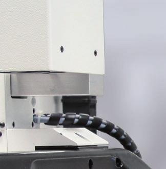


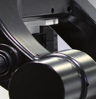
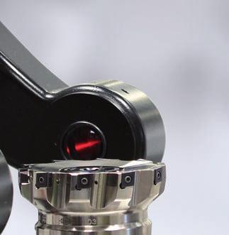
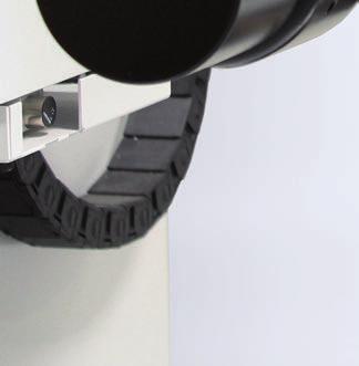
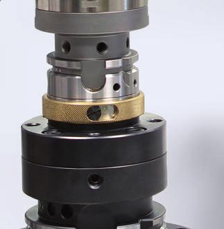

172 172


173 Tools with ISO elements Technical appendix Technical appendix Important technical notes and background information on the MAPAL tools with ISO elements and in general on the boring and milling machining areas are given in the following. Sections for the individual tool groups here you will find general figures for the correct usage of the tools, handling notes, cutting data recommendations and also very specific information such as chip guiding stages on the individual milling tools. The section "Technical notes" also contains machining formulae, assistance with the calculation of cutting forces and an overview of the forms of wear on indexable inserts with suitable rectification measures. General machining formulae 174 Cutting parameters 175 Calculation of cutting forces 176 General figures for the minimum boring diameter 178 Handling notes for TFB fine boring tool system 180 Boring Cutting data recommendation for boring and turning 184 Cutting data recommendation for TFB and TSW 186 Milling Terminology and formulae 188 Technical information 190 Circular and helix milling 192 Handling notes ICM 90-Finishing 195 Handling notes milling cutter retaining screw 196 Cutting data recommendation 198 General Forms of wear on indexable inserts Technical appendix
![Tools with ISO elements Technical appendix General machining formulae, boring General machining formulae, boring Velocity and feed Spindle speed Cutting speed 1 n = [ ] min m v c = [ ] min v c 1000 n](/docs-images/79/80109988/images/174-0.jpg "= D c D c n v c = 1000 Feed rate mm v f = [ ] min v f = f z z n Feed/tooth v f z = [ mm ] f f z = z n Feed/revolution mm f u = [ ] u f u = f z z Number of cutting edges z Cutting force Cutting force")
174 Tools with ISO elements Technical appendix General machining formulae, boring General machining formulae, boring Velocity and feed Spindle speed Cutting speed 1 n = [ ] min m v c = [ ] min v c 1000 n = D c D c n v c = 1000 Feed rate mm v f = [ ] min v f = f z z n Feed/tooth v f z = [ mm ] f f z = z n Feed/revolution mm f u = [ ] u f u = f z z Number of cutting edges z Cutting force Cutting force Fc F c = A k c = b h kc Fc in N kc in N/mm 2 Specific cutting force k k c = [ c 1.1 ] h mc 174
175 Tools with ISO elements Technical appendix Cutting parameters during boring Cutting parameters during, boring Along with the specific cutting force for the material, the cutting cross section A essentially defines the machining force. Feed element per cutting edge fz and cutting depth ap are key parameters here. The following relationships apply: Feed/revolution f u = [mm/u] f u = f z z The figure shows the cutting cross section A during boring. Setting angle Cutting width κ = [ ] b = [mm] σ κ = 2 a p b = sin κ A h σ Chipping thickness h = [mm] h = f z sin κ f b κ Cutting depth a p = [mm] (D d) a p = 2 a p d D Cutting cross section for boring A = [mm 2 ] (D d) f z A = 2 or A = a p f z 175 Technical appendix
176 Tools with ISO elements Technical appendix Calculation of cutting forces, boring Calculation of cutting forces, boring (simplified) ø 80 ø 72 pre-drilled Example calculation: Boring tool ø 80 mm; Z = 5; pre-drilled ø 72 mm κ = 90 Material: EN-GJL-250 kc1.1* = 1160 mc = 0.26 vc 200 m/min fz= 0.2 mm Blunting 30 % Basic formula Calculation Result 1. Spindle speed V c 1000 n = D n = 80 n = 800 1/min 2. Cutting depth (D d) a p = 2 (80 72) a p = 2 a p = 4 mm 3. Cutting cross section A = a p f z A = 4 mm 0,2 mm 5 A = 4 mm 2 4. Chipping thickness h = f z sin κ h = 0,2 mm sin90º h = 0,2 mm 5. Specific cutting force without blunting factor k c k c = h mc k c = 0,2 0,26 k c = 1763 N/mm 2 with 30 % blunting: 1763 N/mm 2 1,3 = 2292 N/mm 2 6. Cutting force F c = A k c = b h kc F c = 4 mm N/mm 2 F c = 9,17 kn 7. Cutting torque dm = average diameter in metres 8. Cutting power d m 0,076 m M c = F c M c = 9167,3 N 2 2 M c = 348,3 Nm 2 n M P c c = 60s min ,3 Nm P c = 60s P c = 29,2 kw * Value for cutting force calculation, WTO GmbH 176 Note: The efficiency of the main spindle drive is not taken into account. Appropriate power calculations can be made by MAPAL.
177 Tools with ISO elements Technical appendix Calculation of cutting forces, boring Machine tool selection: Comparison with torque and output power of the machine tool Motor spindle (Figure 1) Torque (Nm) Power (kw) There follow two spindle speed/power diagrams. The number of teeth and cutting parameters are to be defined as a function of the machine. In the example calculation the machine with the motor spindle is unsuitable, as here at a spindle speed of 800 1/min a torque of 187 Nm and a power of approx. 20 kw is achieved (Figure 1) Nm 100 % 35 kw 100 % , , Torque curve in Nm Power curve in kw Line to assist on reading the diagram Spindle speed (1/min) Solution: Either reduce number of teeth, reduce cutting speed and feed, divide cut between two tools or select more powerful machine (e.g. with geared spindle, (Figure 2). Geared spindle (Figure 2) Torque (Nm) Nm 100 % kw 100 % Power (kw) ,15 2 0,6 The example diagrams are shown in a simplified form Spindle speed (1/min) 177 Technical appendix
178 Tools with ISO elements Technical appendix Minimum boring diameter General figures for the minimum boring diameter radial as a function of the number of teeth and indexable insert ø min Z = 2 ø min Z = 5 κ ap ø min Radial boring cutting edges without arc shaped land Indexable insert form Indexable insert size No. of teeth Comment T S (90 ) C (80 ) T (60 ) Minimum boring diameter at κ 85 ø 17 ø 25 ø 28 1 ø 17 ø 25 ø 31 2 ø 23 ø 32 ø 39 3 ø 31 ø 43 ø 53 4 ø 51 ø 63 ø T Minimum boring diameter at κ 90 ø 17 ø 24 ø 28 1 ø 18 ø 26 ø 33 2 ø 23 ø 34 ø 41 3 ø 31 ø 45 ø 54 4 ø 49 ø 63 ø T T3 Minimum boring diameter at κ 90 ø 15 ø 17 ø 17 ø 24 1 ø 18 ø 21 ø 24 ø 37 2 ø 21 ø 25 ø 28 ø 43 3 ø 27 ø 34 ø 37 ø 57 4 ø 37 ø 51 ø 67 ø 76 5 Suitable for through bore Suitable for 90 shoulder machining Suitable in some situations for through bore and 90 shoulder machining 178
179 Tools with ISO elements Technical appendix Minimum boring diameter General figures for the minimum boring diameter tangential as a function of the number of teeth and indexable insert ø min Z = 2 ø min Z = 5 κ a p ø min Tangential boring cutting edges without arc shaped land Indexable insert form Indexable insert size No. of teeth Comment 0603/ T3/ /1206 C (80 ) Minimum boring diameter at κ 80 and 90 ø 28 ø 41 ø 54 1 ø 28 ø 41 ø 54 2 ø 30 ø 41 ø 54 3 ø 40 ø 56 ø 64 4 ø 59 ø 84 ø 94 5 Suitable for through bore and 90 shoulder machining Tangential boring cutting edges with arc shaped land Indexable insert form Indexable insert size No. of teeth Comment C (80 ) Minimum boring diameter at κ 80 and 90 ø 40 ø 65 ø 78 1 ø 40 ø 65 ø 78 2 ø 40 ø 65 ø 78 3 ø 41 ø 65 ø 78 4 ø 64 ø 86 ø Suitable for through bore and 90 shoulder machining Tangential boring cutting edges with and without arc shaped land Indexable insert form Indexable insert size No. of teeth Comment F (70 ) W (80 ) Minimum boring diameter at κ 80 and 90 ø 22 ø 30 ø 40 1 ø 22 ø 30 ø 40 2 ø 31 ø 43 ø 53 3 ø 42 ø 56 ø 67 4 ø 64 ø 83 ø Minimum boring diameter at κ 80 and 90 ø 37 ø 59,5 2 ø 40,5 ø 59,5 3 ø 54,5 ø 74,5 4 ø 79,5 ø 89,5 5 Suitable for through bore and 90 shoulder machining Suitable for through bore and 90 shoulder machining 179 Technical appendix
.")
. Alignment 1.")


180 Tools with ISO elements Technical appendix Handling notes for TFB fine boring tool system Handling notes for TFB fine boring tool system Radial run-out alignment The handling notes describe the necessary steps for adjusting the MAPAL fine boring tool system comprising machine adapter, KS flange adapter and TFB fine boring head (see right). This task includes the alignment of the Module connection and the correct setting of the tangential indexable inserts using the MapJus fine adjustment feature. For straightforward, convenient, quick and precise setting, it is recommended to use a MAPAL setting fixture (UNISET-V vision, standard). Alignment 1. Clean connection on the setting fixture using a cloth and taper wiper, and check the face surfaces of the connections for indents or protrusions. If necessary dress using an oil stone. Insert machine adapter for the fine boring tool in the connection on the setting fixture. Insert KS flange adapter with KS clamping cartridge in the module on the machine adapter. 2. Tighten axial fastening screws for the KS flange adapter in the clockwise direction (approx. 2 Nm). 3. Fit TFB fine boring head in the HSK connection on the KS flange adapter. Result: The face connections on the KS flange adapter and the HSK connection on the fine boring head are in contact and the key block slots on the tool are engaged. 4. Note: The TFB fine boring head is labelled with the recommended tightening torque. Tighten clamping screw on the HSK connection in the clockwise direction (for tightening torque see Table 1). Relieve the four radial adjusting screws on the module connection. 5. Rough alignment Determine radial run-out error on the KS flange adapter: Place measuring sensor against the surface for checking the radial run-out on the flange adapter and then rotate the tool. Turn the radial adjusting screws in the clockwise direction until the radial run-out error is 5 μm. After making the setting, relieve the adjusting screws. 6. Tighten axial fastening screws in the clockwise direction to 50 % of the stipulated tightening torque (see Table 2). Table 1: Tightening torque and clamping force for the HSK nominal sizes Nominal size Tightening torque [Nm] Clamping force [kn] HSK 50 HSK 63 HSK 80 HSK


.")
 to \"zero\" at the position of largest deflection on the surface for checking the radial run-out on the fine boring head.")
181 Tools with ISO elements Technical appendix Handling notes for TFB fine boring tool system Machine adapter 2 KS flange adapter 3 TFB fine boring head 4 Radial adjusting screw 5 Fastening screw 6 Axial angular alignment screw 7 Clamping screw for the HSK connection 8 KS clamping cartridge Fine alignment Note: After fine alignment the radial run-out error must be < 3 μm. Determine radial run-out error on the KS flange adapter by placing the measuring sensor against the surface for checking the radial run-out and rotating the tool. At the surface for checking the radial run-out, turn the four radial adjusting screws clockwise until the radial run-out error is < 3 μm. Relieve the four radial adjusting screws. 8. Correct angular error Determine radial run-out error on the TFB fine boring head by placing the measuring sensor against the surface for checking the radial run-out on the fine boring head and rotating the tool. If the dial gauge at the position for checking the radial run-out on the fine boring head indicates a fluctuating radial run-out > 3 μm, there is an angular error (see step 9). If there is no angular error, see step Correct angular error Set indication (dial gauge) to "zero" at the position of largest deflection on the surface for checking the radial run-out on the fine boring head. Note: Lock setting fixture's spindle. Turn the axial angular alignment screws on KS flange adapter diagonally in the clockwise direction until the radial run-out error on the TFB fine boring head is < 3 μm. Note: The axial alignment screws must not be relieved after actuation! Result: The angular error has been corrected. 10. Tighten axial fastening screws to the stipulated tightening torque in the clockwise direction (see Table 2). Check again at the surfaces for checking the radial run-out on the TFB fine boring head and the KS flange adapter whether the radial run-out error is < 3 μm. Note: Once the full tightening torque has been reached, no further radial run-out correction is allowed to be made. Slightly tighten radial adjusting screws. Table 2: Tightening torque for Module sizes and fastening screws You will receive the complete instructions on the alignment of the TFB fine boring tool on the purchase of the tool. A PDF version of the complete instructions is also available in the download area at Module size Fastening screw Tightening torque M060 M080 M100 M140 4xM6 4xM6 4xM8 4xM10 20 Nm 20 Nm 36 Nm 72 Nm 181 Technical appendix


182 Tools with ISO elements Technical appendix Handling notes for TFB fine boring head Handling notes TFB fine boring head Changing and setting indexable inserts To be able to achieve very high accuracies on machining bores, MAPAL uses a special adjusting system on the TFB fine boring tool system. Adjustment to the μm is a special feature of this system and makes the replacement of the indexable inserts straightforward and reliable. Changing and setting tangential indexable insert 1. Turn threaded spindle on the MapJus fine adjustment feature one turn counter clockwise using a hex-wrench. 2. Undo TORX PLUS clamping screw for the tangential indexable insert and remove tangential indexable insert from the insert seat. 3. Clean tangential indexable insert and insert seat using compressed air. Turn tangential indexable insert or fit a new indexable insert in the insert seat. Fit TORX PLUS clamping screw in the tangential indexable insert and tighten to 1.5 Nm using a torque wrench. 4. Turn threaded spindle on the MapJus fine adjustment feature 1/2 turn clockwise using a hex-wrench. In this way the necessary preload is generated in the adjusting system. Result: The tangential indexable insert has been changed. 5. Move measuring sensor to the setting pad. Determine highest radial measuring point on the setting pad: turn tool and at the same time monitor the measured data on the display. Move measuring sensor to the highest axial point on the setting pad. Leave tool at the highest measuring point on the setting pad. Set indication (dial gauge) to "zero" at the highest measuring point. 6. Turn tool until tangential indexable insert is in contact with the measuring sensor. Turn tool until the highest radial cutting point on the tangential indexable insert is reached. Move measuring sensor axially until the highest axial cutting point on the tangential indexable insert is reached. 182

183 Tools with ISO elements Technical appendix Handling notes for TFB fine boring head Setting pad 2 MapJus fine adjustment feature 3 Tangential indexable insert 4 TORX PLUS clamping screw 5 Adjusting wedge 6 Threaded spindle 7. Tighten TORX PLUS clamping screw clockwise to Nm using a torque wrench. 8. Note The TFB tools are labelled with the reference pad diameter. Maintain a minimum overhang of 30 μm from the cutting edge to the reference pad. Set required machining diameter: turn clockwise using a hex-wrench on the threaded spindle on the MapJus fine adjustment feature until the indication (dial gauge) indicates the required cutting edge setting dimension. Repeat steps 5 to 8 for the remaining tangential indexable inserts. Result: The tangential indexable inserts have been set to the stipulated machining diameter. Attention: After alignment in the setting fixture, the radial run-out of the tool in the machine tool must also be checked to ensure there is no error in the shape of the bore. In general the following applies: the more exact the setting, the more exact the bore! If there is a radial run-out error on the machine spindle, it may be necessary to re-adjust the radial run-out and angular adjustment on the machine. 183 Technical appendix
184 Tools with ISO elements Technical appendix Cutting data recommendation for boring and turning Cutting data recommendation for boring and turning Cutting speed Note: Values for feed f [mm/z]. See overview of chip guiding stages page Strength [N/mm 2 ] Hardness [HB] Cutting speed v c [m/min] Uncoated carbide Carbide CVD-coated Material HU615 HU810 HC840 HC841 HC851 HC852 HC861 HC862 HP118 HP182 Non-alloy steels, cast steel Up to 600 N/mm 2 Over 600 N/mm P Up to 1000 N/mm Alloyed steels Over 1000 N/mm Stainless steels austenitic Up to 850 N/mm M Stainless steels - martensitic Up to 1100 N/mm Special alloys (Hasteloy, Inconel,...) Up to 1200 N/mm K1 Grey cast iron, alloyed grey cast iron Up to 250 HB Over 250 HB K2 Spheroidal cast iron, vermicular graphite cast iron, malleable cast iron Up to 500 N/mm 2 Over 500 N/mm Aluminium (Si-content < 3 %) N Aluminium (Si-content < 12 %) Aluminium (Si-content > 12 %) Copper, brass, bronze S Titanium alloys
185 Tools with ISO elements Technical appendix Cutting data recommendation for boring and turning Cutting speed v c [m/min] Carbide PVD-coated Ceramic Cermet CVDcoated Cermet PVD-coated PcBN PCD HP350 HP382 HP454 HP455 HP615 HP718 KU450 CC111 CP130 CP131 CP871 CP872 FU430 PU617 PU _ _ Technical appendix
186 Tools with ISO elements Technical appendix Cutting data recommendation for tangential fine boring tools TFB Cutting data recommendation for tangential roughing tools TSW Roughing Medium machining Strength [N/mm 2 ] Hardness [HB] Cutting speed Recommended feed Cutting speed Recommended feed v c [m/min] v c [m/min] Per cutting edge v c [m/min] v c [m/min] Per cutting edge Material Carbide Ceramic + PcBN f z [mm] Carbide Ceramic + PcBN f z [mm] Non-alloy steels, cast steel Up to 600 N/mm 2 Over 600 N/mm ,2-0, ,2-0, ,25-0, ,2-0,35 P Up to 1000 N/mm ,2-0, ,15-0,3 Alloyed steels Over 1000 N/mm ,2-0, ,15-0,3 Stainless steels austenitic Up to 850 N/mm ,15-0, ,15-0,3 M Stainless steels - martensitic Up to 1100 N/mm ,2-0, ,15-0,3 Special alloys (Hasteloy, Inconel,...) Up to 1200 N/mm ,1-0, ,1-0,25 K1 Grey cast iron, alloyed grey cast iron Up to 250 HB Over 250 HB ,15-0, ,1-0, ,15-0, ,1-0,3 K2 Spheroidal cast iron, vermicular graphite cast iron, malleable cast iron Up to 500 N/mm 2 Over 500 N/mm ,15-0, ,1-0, ,15-0, ,1-0,3 Aluminium (Si-content < 3 %) ,15-0, ,1-0,3 N Aluminium (Si-content < 12 %) Aluminium (Si-content > 12 %) ,15-0, ,1-0,3 Copper, brass, bronze ,15-0, ,1-0,3 S Titanium alloys ,08-0, ,05-0,25 186
187 Tools with ISO elements Technical appendix Cutting data recommendation for tangential roughing tools TSW Cutting data recommendation for tangential fine boring tools TFB Finishing Strength [N/mm 2 ] Hardness [HB] Cutting speed Recommended feed v c [m/min] v c [m/min] v c [m/min] v c [m/min] Per cutting edge Carbide Cermet PCD PcBN f z [mm] Material Non-alloy steels, cast steel Up to 600 N/mm 2 Over 600 N/mm ,15-0, ,15-0,35 P Alloyed steels Up to 1000 N/ mm ,15-0,35 Over 1000 N/mm ,15-0,35 Stainless steels austenitic Up to 850 N/mm ,15-0,3 M Stainless steels - martensitic Up to 1100 N/mm ,15-0,3 Special alloys (Hasteloy, Inconel,...) Up to 1200 N/ mm ,15-0,3 K1 Grey cast iron, alloyed grey cast iron Up to 250 HB Over 250 HB ,15-0, ,15-0,35 K2 Up to 500 N/mm 2 Spheroidal cast iron, vermicular graphite cast iron, malleable cast iron Over 500 N/mm ,15-0, ,15-0,3 Aluminium (Si-content < 3 %) ,15-0,35 N Aluminium (Si-content < 12 %) Aluminium (Si-content > 12 %) ,15-0, ,15-0,35 Copper, brass, bronze ,15-0,35 S Titanium alloys Technical appendix
188 Tools with ISO elements Technical appendix Terminology and formulae milling Terminology and formulae, milling Milling cutter diameter Dc [mm] Setting angle κ A A 90 B 75 D c Average roughness Ra [µm] Cutting depth ap [mm] Average roughness depth Rz [µm] Contact width ae [mm] Number of cutting edges z a p a p Spindle speed n [U/min] a e a e Formulae Feed per turn mm f u = [ ] U f u = z f z Feed per tooth mm f z = [ ] tooth v f f z = n z fz during face milling: f z 2 3 f u 188
189 Tools with ISO elements Technical appendix Terminology and formulae milling Spindle speed Average chip thickness Cutting speed 1 n = [ ] min h m = [ mm ] m v c = [ ] min vc 1000 n = D a e h m = sinκ f z D D c n v c = 1000 Feed rate mm v f = [ ] min v f = fz z n Material removal rate cm Q = [ 3 ] min Q = a e a p v f Disc, groove, shoulder milling Feed value compensation fz 0,1 Machining steps with low radial cutting depth such as disc milling, groove milling or milling a shoulder require correction of the feed at the cutting edge as it enters the workpiece. The calculated and actual feed can vary depending on the cutting depth and the milling cutter diameter. 0,02 0,04 0, If a shoulder with a cutting depth of only 0.5 mm is machined using a milling cutter ø 40, the feed must be multiplied with a factor of 5 to arrive at the actual feed or fz 0.1 (see example below). 0,07 Example: A major advantage of the application of this formula is the increase in the productivity on the effective usage of the milling cutter. Tool: Milling cutter ø 40 mm z: 5 fz: 0,1 mm/rev f: 0.5 mm/rev Radial cutting depth [a p ] Feed per tooth [f z ] Maximum chip thickness [h max ] Required v f to obtain f z 0.1 Increase factor 20 0,1 0, , ,1 0, ,11 5 0,1 0, ,43 1,5 0,1 0, ,50 0,5 0,1 0, ,00 Note: Based on the above example, the feed per tooth can be increased with a low ap/d ratio or a setting angle < Technical appendix
190 Tools with ISO elements Technical appendix Technical information milling Technical information milling Selection of the setting angle κ = 90 κ = <90 Advantages: For thin-walled workpieces For poorly clamped workpieces For 90 shoulder machining Disadvantages: Highest radial forces Sudden high load on entering the material Increased probability of the formation of burrs as the cutting edge exits Advantages: For general milling applications Good ratio of cutting edge size to maximum cutting depth Reduced sudden load on the cutting edge on entering the material Disadvantages: Higher radial forces can cause problems in case of low power machines or poorly clamped workpieces The milling cutter diameter and the milling cutter position The milling cutter diameter is to be selected as a function of the size of the workpiece size or the width of the workpiece as well as the power of the machine. During face milling, e.g. the milling cutter diameter should be 20 % - 50 % larger than the cutting width on the workpiece. Optimal milling cutter diameter The position of the milling cutter and the cutting edge contact on entering and exiting the workpiece affect the machining result. Optimal position A e A e 1,2-1,5 x A e D c = A e 190
191 Tools with ISO elements Technical appendix Technical information milling Differentiation based on running direction Counter feed milling Synchronous milling (preferred) On the entry of the cutting edge into the chip-removing cut, the cutting edge has the unfavourable chipping thickness zero and leaves the material with the maximum chipping thickness hmax. Friction is produced during counter feed milling. This friction results in chip bonding and the transfer of heat to the insert and to the workpiece. In the case of counter feed milling the resulting forces are against the direction of feed. It is likely that material strain hardening will occur. Synchronous milling is generally recommended. On entry into the material the cutting edge has a specific feed per tooth and with a maximum chipping thickness hmax generates a chip that becomes thinner on exiting the chip-removing cut. This aspect reduces the heat due to the transmission in the chip. The material strain hardening is minimised. Production of surfaces Axially produced surfaces: During face milling the surface quality is primarily generated by the cutting edge geometry and the feed. Improvement in the surface quality: Compared to a conventional cutting edge geometry, with a wide face indexable insert a Ra and Rz value several times better is achieved with the same feed. Standard geometry Wide finishing geometry R R R t R t f z f z 191 Technical appendix
192 Tools with ISO elements Technical appendix Circular milling Circular milling Circular milling with two-axis feed rate Feed rate at the cutting edge (at the contour) vf [mm/min] Feed rate at the centre of the tool (at tool centre) vfm [mm/min] Circular milling external machining Circular milling internal machining D d d D V f V fm V f V fm D + d v fm = v f D D d v fm = v f D Moving in and out On moving in or out the contour should always be approached or left over a quarter or semi-circle. This action will ensure tangential plunging or removal of the tool from the workpiece. In this way dwell marks on the workpiece are avoided and better circularity of the part machined achieved. 192
193 α Tools with ISO elements Technical appendix Circular milling Two axis angled entry linear (flute) Peripheral cutting edge Face cutting edge Inner cutting edge (trailing) a c b Ramp angle α: The maximum plunge angle α is dependent on the tool. Application notes For end milling cutter ICM90-B2-Shank In case of two-axis angled entry various machining processes take place at the same time: a) Machining at the entire periphery of the tool (peripheral machining) with leading indexable insert b) Machining at the face of the milling cutter with leading insert c) Machining at the face of the milling cutter with trailing insert Plunge milling α Milling cutter Indexable insert that Maximum ramp diameter can be used angle α ø 16, ø 18 3 ø 20 Type BDMT11T3 5 ø 22, ø 25 2,5 ø 28, ø 32 Type BDGT11T3 1,5 ø 40 0,7 ø 25 8 ø 32 Type BDMT ø 40 Type BDGT1704 2,5 ø 50 or more Not recommended Vertical milling Milling cutter diameter Indexable insert that can be used Max. cutting width ae Modified milling cutter type M ICM90-B2-Shank, ICM90-B2, ISM90-B2-Shank, ISM90-B2. a e ø 16 ø 20 - ø 40 Type BDMT11T3 Type BDGT11T3 Type BDMT11T3 Type BDGT11T3 1,5 mm 5 mm If indexable inserts with a radius >1.2 mm are used, the tool body must be reworded at the peripheral edge as per the table shown. In this case the modified milling cutter type M can be selected (see section Milling pages 49-53) Alternatively the standard milling cutter can also be ordered and re-worked by the customer. ø 25 - ø 40 For shoulder cutter head ICM90-B2 Plunge milling Milling cutter diameter Type BDMT1704 Type BDGT1704 Indexable insert that can be used 8 mm Maximum ramp angle α Standard Re-worked α ø 40 2,5 Type BDMT1704 Type BDGT1704 ø 50 or more Not recommended Vertical milling Milling cutter diameter Indexable insert that can be used Maximum cutting width a e Indexable insert radius Radius required on the tool body 2,0 1,0 3,1 1,6 4,0 2,5 a e ø 25 - ø 40 Type BDMT1704 Type BDGT mm 193 Technical appendix
: The pitch (P) corresponds to the axial material removal rate per revolution.")
194 Tools with ISO elements Technical appendix Helix milling Helix milling Helical angled entry Helical angled entry is an alternative to drilling. During this process a circular movement is made with simultaneous axial feed. Pitch (P): The pitch (P) corresponds to the axial material removal rate per revolution. This aspect is dependent on the workpiece, tool length, material and machine. P Advantages compare to circular milling Better circularity and concentricity Better cutting behaviour on applications susceptible to vibration Constant angled entry into the workpiece The milling cutter is continuously engaged, no entering or exiting per revolution compared to circular milling Application note α Tool ø Max. possible plunge angle α 80 4, , , , ,1 Selection of the milling cutter diameter as a function of the size of the bore In the case of centre-cutting milling cutters it is important to select the correct ratio of milling cutter diameter and bore diameter. The insert must cut along the centre axis. If the milling cutter diameter is too small, there is a core in the centre. If the milling cutter diameter is too large, the centre is not machined. As a result a protrusion is left. This protrusion presses the milling cutter axially. There is a collision between the workpiece and tool Drilling into the solid (flat bottom of the bore) Milling cutter diameter (mm) Bore diameter (mm) Note: In the case of a bore diameter between the ranges stated, for example 170 mm, the smaller milling cutter with a diameter of 80 mm is selected. Two machining steps are then necessary to machine the bore. 2 Enlarging a bore (no face machining) Milling cutter diameter = < 0.5 x bore diameter 194

. 1.")


195 Tools with ISO elements Technical appendix Handling notes ICM 90-Finishing Handling notes ICM90-Finishing Mounting and setting indexable inserts Condition as delivered (without indexable insert). 1. Unscrew TORX clamping screws and clean indexable insert seat if necessary. 2. Using a hex-wrench unscrew counter clockwise the adjusting wedge to approx. 1 mm above the tool body. 3. Fit indexable insert and TORX clamping screw and tighten clockwise to 2.8 Nm using a TORX torque wrench. 4. Screw in adjusting wedge clockwise using a hexwrench until it is in contact with the indexable insert. 5. Identify highest indexable insert in the fixed insert seat and zero dial gauge. 6. Turn tool until the finishing insert is in the measuring position. Move to highest radial cutting point. 7. By turning the threaded spindle for the adjusting element clockwise, adjust the wide finishing insert to 0.02 mm - maximum 0.04 mm overhang in relation to the highest indexable insert in the fixed insert seat. The wide finishing inserts should be set to < 5 µm axially in relation to each other. Information: The required preload on the indexable insert is generated by the adjusting element. 195 Technical appendix


196 Tools with ISO elements Technical appendix Handling notes milling cutter retaining screw Milling cutter retaining screw for the highest clamping force and reliability Threaded ring Threaded bolt Areas of application: Disk milling cutter with arbor Higher cutting force when machining High torques Advantages: Very high clamping force Greater reliability through the different thread pitches in contact with threaded bolt Self-locking No risk of injury through slipping wrenches High cost effectiveness thanks to greater circular and face run-out of the milling cutter 196


![Wrench size Tightening Torque [Nm] 10041356 16 M8 5 28 10009642 22 M10 6 50 10006125 27 M12 8 70](/docs-images/79/80109988/images/197-7.jpg "10009686 32 M16 10 95 10006126 40 M20 12 125 8.")
197 Tools with ISO elements Technical appendix Handling notes milling cutter retaining screw Handling notes Tool clamping 1. Remove drive ring from milling cutter arbor. 2. Install key block in milling cutter arbor. Note: Spacers are not included in scope of delivery. See capital accessories and spare parts page Place first spacer on milling cutter arbor. Note: Spacers are not included in scope of delivery. See capital accessories and spare parts page Place tool on face surface of milling cutter arbor. 4. Place second spacer on first spacer and milling cutter arbor. Mount and set milling cutter retaining screw 6. Rotate thread bolt so long that a 2 mm overhang to the threaded ring is reached. Tightening torque for milling cutter retaining screws Retaining Screw For milling cutter arbor-ø [mm] Dimensions M 7. Lightly turn the milling cutter retaining screw into the milling cutter arbor in a clockwise direction. Wrench size Tightening Torque [Nm] M M M M M Turn the milling cutter retaining screw further in a clockwise direction into the milling cutter using an allen key and tighten to the tighten torque given in the tighten torque table. Result: Milling cutter retaining screw is tightened to the correct tightening torque and rest on the face of the tool. Note: To be used only by trained personnel. 197
198 Tools with ISO elements Technical appendix Cutting data recommendation for milling Cutting data recommendation for milling Cutting speed Cutting speed Strength [N/mm 2 ] Hardness [HB] v c [m/min] Uncoated carbide Carbide PVD-coated Material HU615 HU810 HU825 HP350 HP382 HP615 HP718 HP883 HP890 Non-alloy steels, cast steel Up to 600 N/mm 2 Over 600 N/mm P Up to 1000 N/mm Alloyed steels Over 1000 N/mm Stainless steels austenitic Up to 850 N/mm M Stainless steels - martensitic Up to 1100 N/mm Special alloys (Hasteloy, Inconel,...) Up to 1200 N/mm K1 Grey cast iron, alloyed grey cast iron Up to 250 HB Over 250 HB K2 Spheroidal cast iron, vermicular graphite cast iron, malleable cast iron Up to 500 N/mm 2 Over 500 N/mm Aluminium (Si-content < 3 %) N Aluminium (Si-content < 12 %) Aluminium (Si-content > 12 %) Copper, brass, bronze S Titanium alloys
199 Tools with ISO elements Technical appendix Cutting data recommendation for milling PcBN PCD FU430 PU617 PU Technical appendix
200 Tools with ISO elements Technical appendix Cutting data recommendation for milling Cutting data recommendation for milling Feed per tooth Face cutter head with tangential technology IFM75-C2 Indexable insert Chip guiding stage Edge rounding Feed/tooth (mm) D00 D01 D02 D03 D61 D67 D81 D87 CTHD CTHD CTHD/CTND CTND CTHD CTHD CTHD CTHD P 0,1-0,25 0,1-0,25 M 0,08-0,2 K 0,08-0,4 0,1-0,4 0,05-0,4 0,05-0,4 N 0,05-0,5 0,05-0,5 0,05-0,5 0,05-0,5 S 0,05-0,2 0,08-0,2 IFM75-C2 Indexable insert Chip guiding stage Edge rounding Feed/tooth (mm) H03 H12 H21 H22 A61 A67 A81 A87 CTHQ CTHQ CTHQ CTHQ CTHQ CTHQ CTHQ CTHQ P 0,1-0,25 M 0,08-0,2 K 0,08-0,3 0,05-0,3 0,05-0,3 N 0,08-0,4 0,05-0,4 0,08-0,4 0,05-0,4 0,05-0,4 S 0,08-0,2 Shoulder cutter head with tangential technology ICM90-C2 Indexable insert ICM90-C2-Finishing Chip guiding stage Edge rounding Feed/tooth (mm) D00 D01 D02 D03 D61 D67 D81 D87 CTHD CTHD CTHD/CTND CTND CTHD CTHD CTHD CTHD P 0,1-0,25 0,1-0,25 M 0,08-0,2 K 0,08-0,4 0,1-0,4 0,05-0,4 0,05-0,4 N 0,05-0,5 0,05-0,5 0,05-0,5 0,05-0,5 S 0,05-0,2 0,08-0,2 ICM90-C2-Finishing 200 Optional wide face indexable insert Chip guiding stage* Edge rounding Feed/tooth (mm) H25 H26 D81 D87 CTHA CTHA CTHA CTHA P 0,1-0,25 M 0,08-0,2 K 0,05-0,4 0,05-0,4 0,05-0,4 N 0,05-0,5 0,05-0,5 0,05-0,5 S 0,05-0,2
201 Tools with ISO elements Technical appendix Cutting data recommendation for milling 0 = Sharp edged + = Slightly rounded ++ = Medium rounded +++ = Heavily rounded Shoulder cutter head with tangential technology ICM90-C4 Indexable insert ICM90-C4-Finishing Chip guiding stage Edge rounding Feed/tooth (mm) H03 H12 H21 H22 A61 A67 A81 A87 CTHQ CTHQ CTHQ CTHQ CTHQ CTHQ CTHQ CTHQ P 0,1-0,25 M 0,08-0,2 K 0,08-0,3 0,05-0,3 0,05-0,3 N 0,08-0,4 0,05-0,4 0,08-0,4 0,05-0,4 0,05-0,4 S 0,08-0,2 ICM90-C4-Finishing Optional wide finishing indexable insert Chip guiding stage* Edge rounding Feed/tooth (mm) H25 H26 A81 A87 CTHH CTHH CTHH CTHH P 0,1-0,25 M 0,08-0,2 K 0,05-0,3 0,05-0,3 0,05-0,3 N 0,05-0,4 0,05-0,4 0,05-0,4 S 0,08-0,2 Shoulder cutter head with radial technology ICM90-S4 Indexable insert Chip guiding stage Edge rounding Feed/tooth (mm) M65 SEMT +++ P 0,15-0,25 M 0,15-0,2 K 0,15-0,25 N 0,15-0,25 S 0,15-0,2 * The feed/revolution (f u ) is calculated using the total number of teeth. 201 Technical appendix
 M70 R70 R72 R73 R74 U70 U71 BDMT BDMT BDMT BDMT BDMT BDGT BDGT ++ +++ +++ +++ +++ + 0 P 0,08-0,18 0,06-0,25 0,08-0,15 0,08-0,15")
202 Tools with ISO elements Technical appendix Cutting data recommendation for milling Cutting data recommendation for milling Feed per tooth End milling cutter with radial technology ICM90-B2-Shank Indexable insert Chip guiding stage Edge rounding Feed/tooth (mm) M70 R70 R72 R73 R74 U70 U71 BDMT BDMT BDMT BDMT BDMT BDGT BDGT P 0,08-0,18 0,06-0,25 0,08-0,15 0,08-0,15 0,08-0,15 M 0,06-0,12 0,06-0,15 0,08-0,12 0,08-0,12 0,08-0,12 K 0,06-0,25 0,08-0,15 0,08-0,15 0,08-0,15 N 0,05-0,3 0,05-0,2 S 0,06-0,2 0,08-0,12 0,08-0,12 0,08-0,12 0,05-0,2 Shoulder cutter head with radial technology ICM90-B2 Indexable insert Chip guiding stage Edge rounding Feed/tooth (mm) M70 R70 R73 R74 U70 U71 BDMT BDMT BDMT BDMT BDGT BDGT P 0,08-0,18 0,06-0,25 0,08-0,15 0,08-0,15 M 0,06-0,12 0,06-0,15 0,08-0,12 0,08-0,12 K 0,06-0,25 0,08-0,15 0,08-0,15 N 0,05-0,3 0,05-0,2 S 0,06-0,2 0,08-0,12 0,08-0,12 0,05-0,2 Shell end face milling cutter with radial technology ISM90-B2-Shank Indexable insert Chip guiding stage Edge rounding Feed/tooth (mm) M70 R70 R72 R73 U70 U71 BDMT BDMT BDMT BDMT BDMT BDGT P 0,08-0,18 0,06-0,25 0,08-0,15 0,08-0,15 M 0,06-0,12 0,06-0,15 0,08-0,12 0,08-0,12 K 0,06-0,25 0,08-0,15 0,08-0,15 N 0,05-0,3 0,05-0,2 S 0,06-0,2 0,08-0,12 0,08-0,12 0,05-0,2 ISM90-B2 Indexable insert Chip guiding stage Edge rounding Feed/tooth (mm) M70 R70 R72 R73 U74 U70 U71 BDMT BDMT BDMT BDMT BDMT BDGT BDGT P 0,08-0,18 0,06-0,25 0,08-0,15 0,08-0,15 0,08-0,15 M 0,06-0,12 0,06-0,15 0,08-0,12 0,08-0,12 0,08-0,12 K 0,06-0,25 0,08-0,15 0,08-0,15 0,08-0,15 N 0,05-0,3 0,05-0,2 S 0,06-0,2 0,08-0,12 0,08-0,12 0,08-0,12 0,05-0,2 202
203 Tools with ISO elements Technical appendix Cutting data recommendation for milling 0 = Sharp edged + = Slightly rounded ++ = Medium rounded +++ = Heavily rounded Shell end face milling cutter with tangential technology ISM90-C2-SK ISM90-C2-HSK Indexable insert Chip guiding stage Edge rounding Feed/tooth (mm) D00 D01 D02 D03 D81 D87 CTHD CTHD CTHD/CTND CTND CTHD CTHD P 0,1-0,25 0,1-0,25 M 0,08-0,2 K 0,08-0,4 0,1-0,4 0,05-0,3 N 0,05-0,5 0,05-0,5 0,05-0,4 S 0,05-0,2 0,08-0,2 ISM90-C4-SK ISM90-C4-HSK Indexable insert Chip guiding stage Edge rounding Feed/tooth (mm) H03 H12 H21 H22 A81 A87 CTHQ CTHQ CTHQ CTHQ CTHQ CTHQ P 0,1-0,25 M 0,08-0,2 K 0,08-0,3 0,05-0,3 N 0,08-0,4 0,05-0,4 0,08-0,4 0,05-0,4 S 0,08-0,2 Helix milling cutter with tangential technology IHM90-C2 IHM90-C2-HSK Indexable insert Chip guiding stage Edge rounding Feed/tooth (mm) D00 D01 D02 D03 D81 D87 CTHD CTHD CTHD/CTND CTND CTHD CTHD P 0,1-0,25 0,1-0,25 M 0,08-0,2 K 0,08-0,4 0,1-0,4 0,05-0,3 N 0,05-0,5 0,05-0,5 0,05-0,4 S 0,05-0,2 0,08-0,2 IHM90-C4 IHM90-C4-HSK Indexable insert Chip guiding stage Edge rounding Feed/tooth (mm) H03 H12 H21 H22 A81 A87 CTHQ CTHQ CTHQ CTHQ CTHQ CTHQ P 0,1-0,25 M 0,08-0,2 K 0,08-0,3 0,05-0,3 N 0,08-0,4 0,05-0,4 0,08-0,4 0,05-0,4 S 0,08-0,2 203 Technical appendix
204 Tools with ISO elements Technical appendix Cutting data recommendation for milling Cutting data recommendation for milling Feed per tooth Disc milling cutter with tangential technology IDM90-C2-L/R Indexable insert Chip guiding stage Edge rounding Feed/tooth (mm) D00 D01 D02 D03 D61 D67 D81 D87 CTHD CTHD CTHD/CTND CTND CTHD CTHD CTHD CTHD P 0,1-0,25 0,1-0,25 M 0,08-0,2 K 0,08-0,4 0,1-0,4 0,05-0,4 0,05-0,4 N 0,05-0,5 0,05-0,5 0,05-0,5 0,05-0,5 S 0,05-0,2 0,08-0,2 IDM90-C2-LR Indexable insert Chip guiding stage Edge rounding Feed/tooth (mm) D00 D01 D02 D03 D81 D87 CTHD CTHD CTHD/CTND CTND CTHD CTHD P 0,1-0,25 0,1-0,25 M 0,08-0,2 K 0,08-0,4 0,1-0,4 0,05-0,4 N 0,05-0,5 0,05-0,5 0,05-0,5 S 0,05-0,2 0,08-0,2 IDM90-C4-L/R Indexable insert Chip guiding stage Edge rounding Feed/tooth (mm) H03 H12 H21 H22 A61 A67 A81 A87 CTHQ CTHQ CTHQ CTHQ CTHQ CTHQ CTHQ CTHQ P 0,1-0,25 M 0,08-0,2 K 0,08-0,3 0,05-0,3 0,05-0,3 N 0,08-0,4 0,05-0,4 0,08-0,4 0,05-0,4 0,05-0,4 S 0,08-0,2 204
 H03 H12 H21 H22 A81 A87 CTHQ CTHQ CTHQ CTHQ CTHQ CTHQ +++ ++ + ++ + + P 0,1-0,25 M 0,08-0,2 K 0,08-0,3")
205 Tools with ISO elements Technical appendix Cutting data recommendation for milling 0 = Sharp edged + = Slightly rounded ++ = Medium rounded +++ = Heavily rounded Disc milling cutter with tangential technology IDM90-C4-L/R Indexable insert Chip guiding stage Edge rounding Feed/tooth (mm) H03 H12 H21 H22 A81 A87 CTHQ CTHQ CTHQ CTHQ CTHQ CTHQ P 0,1-0,25 M 0,08-0,2 K 0,08-0,3 0,05-0,3 N 0,08-0,4 0,05-0,4 0,08-0,4 0,05-0,4 S 0,08-0,2 IDM88-L8-L/R Indexable insert Chip guiding stage Edge rounding Feed/tooth (mm) H83 H93 LTHU LTHU P 0,1-0,3 0,15-0,3 M K 0,1-0,35 0,15-0,35 N S 205 Technical appendix

 Chipping tangential radial - Increase cutting speed - Reduce")

206 Tools with ISO elements Technical appendix Forms of wear Forms of wear on indexable inserts Form of wear Clearance surface wear tangential radial Rectification measures - Reduce cutting speed - Select more wear-resistant cutting material Crater wear tangential radial - Reduce feed - Reduce cutting speed - Select more wear-resistant cutting material - Use coolant Scoring tangential radial - Reduce cutting speed - Select smaller setting angle - Reduce feed Built-up edge tangential radial - Increase cutting speed - Increase feed - Select geometry with lighter cut (sharp cutting edges) Chipping tangential radial - Increase cutting speed - Reduce feed - Select more ductile type of carbide - Select stronger geometry - Improve stability (for example short tool) - Cooling, continuous or dry (avoid thermal shock) Cutting edge fracture tangential radial - Reduce feed - Reduce cutting depth - Select stronger indexable insert geometry - Select more ductile type of carbide - Select thicker insert 206


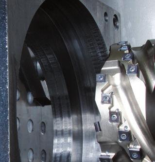
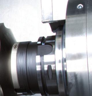


207 Tools with ISO elements Technical appendix 207 Technical appendix

208 Tools with ISO elements MAPAL competence worldwide MAPAL competence MAPAL is the major specialist for complete machining tasks. As a result MAPAL offers complete tool know-how for machining parts. The programme ranges from high-performance standard tools to complex custom tools. Absolute precision is the basis for the quality of MAPAL tools. The result is dependable tool concepts that ensure reliable manufacture. Excellent quality in relation to surface roughness, circularity, cylindricity and maximum tool lives are the consequence. 208
Technology Workpieces and processes in the automotive industry
 Technology Workpieces and processes in the automotive industry New machining solutions for that extra productivity and cost-effectiveness MAPAL technology: Tap the potential savings during the machining
Clamping tools with flange module
 Clamping tools with flange module MAPAL clamping tools with flange module are recommended for machining conditions in which radial run-out and angular error on the machine spindle must be compensated.
Technology Energy-efficient tool concepts
 Technology Energy-efficient tool concepts Save energy and costs with intelligent process management MAPAL technology: Our contribution to energy efficiency You do not need to be a great prophet to predict
Reaming and fine boring. EasyAdjust-System Simpler, faster, more cost-effective
 Reaming and fine boring EasyAdjust-System Simpler, faster, more cost-effective Never before it had been possible to adjust tools so fast and at such a precision. 2 MAPAL EasyAdjust-System Introduction
Reaming. MAPAL MonoReam. Systematic versatility NEW
 Reaming MAPAL MonoReam Systematic versatility NEW MAPAL MonoReam With the newly developed multi-bladed reamers in the 600, 700 and 800 series, MAPAL is offering a new, simple, highperformance, standardised
Lightweight HSC milling cutter for a perfect surface finish. flycutter - system eco
 Lightweight HSC milling cutter for a perfect surface finish flycutter - system eco 2 milling FlyCutter - System Eco mapal FlyCutter - System Eco The FlyCutter series represent a new dimension in face milling
Competence Gun Boring. KOYEMANN Floating Tools Power Reamer
 Competence Gun Boring KOYEMANN Floating Tools Power Reamer R The KOYEMANN Floating Principle Reaming has been used for fine machining bores with excellent results from the very start of cutting technology.
X3-Solutions for mobility
 X3-s for mobility X3-s for mobility 3-SOLUTIONS FOR MOBILITY The mobility of people and goods is the deciding factor for life worldwide and is the motor for global economy. One of the greatest challenges
MILLING Milling cutters with replaceable inserts
 _FRAESEN _DE_EN_V.indd.. : 9 FACE MILLING CUTTERS WITH PCD MILLING CARTRIDGES Introduction to the technology EcoMill and PowerMill EcoMillBlue and RapidMillBlue FlyCutter 4 Reconditioning face milling
MILLING Milling cutters with replaceable inserts
 218 04_FRAESE 2016_DE_E_V1.indd 218 12.12.16 16:54 219 HELIX MILLIG CUTTERS Introduction to the technology Helix milling cutters with indexable inserts 220 IHM90 tangential technology 222 IHM90C2HSK, IHM90C4HSK
PF 3000 Face Milling Cutter
 Perfection in machining PF 3000 Face Milling Cutter UHRIN YOUR WORLD-WIDE PARTNER ADVANTAES axially adjustable inserts standard tool Ø 63 250 available ex-stock reduced spindle loading thanks to light
Milling. CPMill ball track milling cutters. Easy handling and high precision NEW
 Milling CPMill ball track milling cutters Easy handling and high precision NEW CPMill - Complete Performance Milling The new generation of MAPAL replaceable milling cutters for the machining of constant-velocity
UPDATED. PCD & CBN Tangential Milling. Features:
 Diameters Metric: 5.0 mm 50 mm Inch:.0 0.0 Bodies Cylindrical Shell Type Integral on request UPDATED PCD & CBN Tangential Milling TEDIFEED is the newest line of mill with tangential inserts available with
Various other types of drilling machines are available for specialized jobs. These may be portable, bench type, multiple spindle, gang, multiple
 Drilling The process of making holes is known as drilling and generally drilling machines are used to produce the holes. Drilling is an extensively used process by which blind or though holes are originated
HSS Specialists. Special design high speed steel drills for special machining tasks
 HSS Specialists Special design high speed steel drills for special machining tasks Guhring s HSS Guhring has been a specialist in drilling tools for more than a century. This not only applies to the broad
Automotive solutions for ISO K
 Automotive solutions for ISO K When machining in ISO K materials, you need tough tools that can withstand high abrasive wear and frittering, and deliver secure and precise machining again and again. This
In hall 4, stand A42, you can experience Intelligence in Production. The following trade show highlights can be seen at EMO:
 Guhring at EMO 2013 Intelligence in Production with precision tools from Guhring In the spirit of the motto of this year s EMO, from 16th to 21th September in Hanover, Guhring is introducing trendsetting
RATIO. 60 % longer tool life. Ratio high-performance roughing cutter with flat knuckle-type teeth
 INNOVATIONS 2017/2018 Ratio high-performance roughing cutter with flat knuckle-type teeth 60 % longer tool life The optimised roughing geometry with asymmetrical knuckles reduces the cutting pressure in
5-axis clamping system compact
 5-axis clamping system compact 395 5-axis clamping system compact Function We are setting standards with the new KIPP 5-axis clamping system compact in this field. The system was specifically designed
MIKRON HPM 1150U HPM 1350U
 MIKRON HPM 1150U HPM 1350U High performance milling versus high speed milling - the one cannot replace the other! While with high speed milling the objective is to create as much surface on the workpiece
Clamping devices 521
 Clamping devices 521 522 Product overview Clamping devices Adjustable straps K0001 Hook clamps K0012 Goose-neck straps with long slot K0002 Page 526 Hook Clamps with collar K0013 Page 535 Equipped clamps
Flexible tool overhang lengths possible by combining the modular extension arbor and shank with insert run-out adjustment mechanism
 Sumi Easy insert replacement Characteristics Achieves efficiency through high speed, high feeding ability!! (v c =50 to 500m/min, f = 0.4 to 1.2mm/rev) Compatibility with a wide range of cutting conditions
LEADING SOLUTIONS IN THREAD MILLING TECHNOLOGY
 LEADING SOLUTIONS IN THREAD MILLING TECHNOLOGY Thread with Maximum Confidence, Depth, Versatility and Economy. Emuge Shur-Thread TM, Threads-All TM, Vario-Z and NPT Solid Carbide Thread Mills; and Gigant-ic
NPA. Expansion of the HM390 Triangular Inserts Line with Tools Carrying 5 mm Edged Inserts. New Product Announcement. Page 1 / 9
 NPA Expansion of the HM390 Triangular Inserts Line with Tools Carrying 5 mm Edged Inserts Page 1 / 9 Page 2 / 9 Highlights Tools carrying triangular inserts with 5 mm helical cutting edges Effective and
New generation of the PCD face milling cutters. EcoMill-Blue and RapidMill-Blue
 New generation of the PCD face milling cutters EcoMill-Blue and RapidMill-Blue 2 EcoMill-Blue and RapidMill-Blue New generation of the PCD face milling cutters EcoMill-Blue and RapidMill-Blue New generation
AUTOMOTIVE TOOL SOLUTIONS FOR INDUSTRIES
 AM18 AUTOMOTIVE TOOL SOLUTIONS FOR INDUSTRIES HEAD OFFICE 211, Sewolcheon-ro, Bupyeong-gu, Incheon, South Korea Phone : +82-2-526-0909 E-mail : yg1@yg1.kr www.yg1.kr Note The new address above has currently
Tooltech Precision Reamers are designed to meet hole geometry requirements in the complex and demanding machining environment of today s manufacturing
 BLADED REAMERS Tooltech Precision Reamers are designed to meet hole geometry requirements in the complex and demanding machining environment of today s manufacturing industry. The innovative design of
Chapter 23: Machining Processes: Turning and Hole Making
 Manufacturing Engineering Technology in SI Units, 6 th Edition Chapter 23: Machining Processes: Turning and Hole Making Chapter Outline 1. Introduction 2. The Turning Process 3. Lathes and Lathe Operations
Reaming. Tool Systems
 Milling Thread Milling Trapezoid thread ACME thread Knuckle thread TC 50 / TC 80 18-79 1 Face Finish Milling 80-85 2 Notch Impact Test 86-91 3 Gear Milling 92-95 4 Slot Milling 96-123 5 Contour and Radius
APRIL 2009 / NEW-100 / PAGE 1 OF 13
 APRIL 2009 / NEW-100 / PAGE 1 OF 13 The standard UNIDEX line covers reaming applications from 5/16 to 1 1/4 diameter. The single indexable blade and high wear resistant carbide or cermet pads provide a
MAXIMILL SHOULDER MILLING SYSTEM PRODUCT INFORMATION. Presentation _Customer
 MAXIMILL 491 90 SHOULDER MILLING SYSTEM PRODUCT INFORMATION Presentation _Customer 2 \ MAXIMILL 491 PRODUCT LAUNCH AGENDA General information Overall message Unique sales proposition Technical details
New. Products2013.
 T u n g a l o y www.tungaloy.com Company Overview Providing Complete Tooling Solutions for the Metal Removal and Industrial Product Sectors TUNGALOY is one of the world s leading manufacturers of carbide
Thread Mills. Solid Carbide Thread Milling Cutters
 Thread Mills Solid Carbide Thread Milling Cutters Thread milling cutters by Features and Benefits: Sub-micro grain carbide substrate Longer tool life with tighter tolerances More cost-effective than indexable
Chapter 22 MACHINING OPERATIONS AND MACHINE TOOLS
 Chapter 22 MACHINING OPERATIONS AND MACHINE TOOLS Turning and Related Operations Drilling and Related Operations Milling Machining Centers and Turning Centers Other Machining Operations High Speed Machining
CoroMill. All solutions at a glance
 CoroMill All solutions at a glance CoroMill Product overview Milling grades according to groups Shoulder milling CoroMill 316 CoroMill 490 CoroMill 790 Long edge cutter Insert size Max. cutting depth a
KYOCERA UNIMERCO. PCD tools. UM DANDIA TM tooling solutions for the automotive industry
 KYOCERA UNIMERCO PCD tools UM DANDIA TM tooling solutions for the automotive industry KYOCERA UNIMERCO your innovative partner KYOCERA UNIMERCO is specialised in the manufacture of high performance PCD
Solid Carbide Thread Milling Cutters
 Solid Carbide Thread Milling Cutters Second Edition Thread milling cutters by Features and Benefits: Sub-micro grain carbide substrate Longer tool life with tighter tolerances More cost-effective than
DATRON HIGH-SPEED MILLING TOOLS
 DATRON HIGH-SPEED MILLING TOOLS 2017/2018 Smart Manufacturing Solutions DATRON HIGH-SPEED MILLING TOOLS Precision. Power. In Aluminium and More 2017/2018 All previous prices lose their validity with this
STAMPING TECHNOLOGY - CLAMPING RAW PARTS
 simple. gripping. future. 5-Axis 66 Makro Grip Stamping Unit 72 Stamping Unit for the workbench 73 Stamping Unit on trolley 76 Stamping Unit Accessories 77 Stamping Jaws 78 Makro Grip 5-Axis-Vices 82 5-Axis
Special reamers. Figure N 1 Reamer with descending cutting edges in carbide (Cerin)
") Special reamers There is a wide category of special reamers, ie non-standard, that are suitable to address particular problems encountered in the finishing holes, both for maintenance of individual pieces
Special reamers There is a wide category of special reamers, ie non-standard, that are suitable to address particular problems encountered in the finishing holes, both for maintenance of individual pieces
Product Overview. for perfect connections
 Product Overview for perfect connections TOOL HOLDERS FOR DRILLING, TAPPING & REAMING Smart solutions for high quality clamping systems in tapping applications Tapping solution range from M1 M200 Quick
Reamer Basics. Fixed Reamers The reamer size is fixed and any size reduction due to wear or sharpening cannot be reclaimed
 1 Reamer Basics Reamers are available in a variety of types, materials, flute styles and sizes The typical reamer is a rotary cutting tools designed to machine a previously formed hole to an exact diameter
WM en. Zero point clamping system SPEEDY airtec 1
 SPEEDY airtec 1 GO! Maximum productivity Using the zero point clamping system SPEEDY classic you will increase your productivity to a maximum. Adjustment and checking processes are no longer necessary
HOLLFELDER CUTTING TOOLS. Main Catalog H6
 HOLLFELDER CUTTING TOOLS Main Catalog H6 HOLLFELDER-GÜHRING CUTTING TOOLS Your competent partner in the area of metal chip removal. At our two company locations in Nuremberg und Zorbau (Germany) we design
TOMORROW S TOOLING TODAY SECO NEWS SUMMARY
 TOMORROW S TOOLING TODAY SECO NEWS SUMMARY 2018.1 TOOLS FOR LIMITLESS PRODUCTIVITY AND PROFITABILITY JETSTREAM TOOLING WELCOME TO SECO NEWS SUMMARY 2018.1 Discover how the latest Seco innovations, many
Tooling concepts Gear milling.
 Tooling concepts Gear milling Complete gear-cutting solutions optimized for your needs About ninety percent of all gear wheel manufacturing involves metal cutting. Your main opportunities for rationalizing
CoroMill QD. High-security groove milling
 CoroMill QD High-security groove milling The main challenge in groove milling is usually chip evacuation, especially when machining deep and narrow grooves. CoroMill QD is the first cutter of its kind
Chapter 23: Machining Processes: Hole Making Part A (Lathe Operations, Boring, Reaming, Tapping)
") 1 Manufacturing Processes (2), IE-352 Ahmed M El-Sherbeeny, PhD Spring 2017 Manufacturing Engineering Technology in SI Units, 6 th Edition Chapter 23: Machining Processes: Hole Making Part A (Lathe Operations,
1 Manufacturing Processes (2), IE-352 Ahmed M El-Sherbeeny, PhD Spring 2017 Manufacturing Engineering Technology in SI Units, 6 th Edition Chapter 23: Machining Processes: Hole Making Part A (Lathe Operations,
Deburring tools GUHRING YOUR WORLD-WIDE PARTNER. EW 100 G Deburring fork EWR 500 Deburring reamer EW 100 S Deburring spiral. Chamfering milling cutter
 EW 100 G Deburring fork EWR 500 Deburring reamer EW 100 S Deburring spiral Chamfering milling cutter Front/back deburrer Ball nose deburrer EW Deburring reamer EWR 500 Deburring tools GURIG YOUR WORLD-WIDE
MACHINING PROCESSES: TURNING AND HOLE MAKING. Dr. Mohammad Abuhaiba 1
 MACHINING PROCESSES: TURNING AND HOLE MAKING Dr. Mohammad Abuhaiba 1 HoweWork Assignment Due Wensday 7/7/2010 1. Estimate the machining time required to rough cut a 0.5 m long annealed copper alloy round
Automotive Fasteners for Automotive Industry
 Automotive Fasteners for Automotive Industry PEINER Umformtechnik GmbH Woltorfer Straße 20-24 D-31224 Peine Phone + 49 (0) 5171 545-0 Fax + 49 (0) 5171 545-180 e- mail sales@peiner-ut.com Internet www.peiner-ut.com
SPK Cutting Tool. BFL MILLING SYSTEM Plunge Milling, Helical Milling and Helical Interpolation
 SPK Cutting Tool VEHICLES AEROSPACE GEAR + BEARING ENGINEERING WIND ENERGY BFL MILLING SYSTEM Plunge Milling, Helical Milling and Helical Interpolation AEROSPACE The aerospace industry places extremely
Typical Parts Made with These Processes
 Turning Typical Parts Made with These Processes Machine Components Engine Blocks and Heads Parts with Complex Shapes Parts with Close Tolerances Externally and Internally Threaded Parts Products and Parts
Powerful solutions. for your windmill production
 Powerful solutions for your windmill production Do you need to boost productivity? Invite a yellow coat. Windmills are fantastic, producing energy from an endless source without waste. Their increasing
LIVE CENTRES FACE DRIVERS
 LIVE CENTRES FACE DRIVERS 2017 NEW RÖHM eshop First B2B eshop of the clamping technology industry Buy RÖHM products online 24/7 Order as a guest customer without registration Intuitive search and filter
Precision made in Germany. As per DIN The heart of a system, versatile and expandable.
 1 Precision made in Germany. As per DIN 8606. The heart of a system, versatile and expandable. Main switch with auto-start protection and emergency off. Precision lathe chuck as per DIN 6386 (Ø 100mm).
TOMORROW S TOOLING TODAY SECO NEWS SUMMARY
 TOMORROW S TOOLING TODAY SECO NEWS SUMMARY 2018.1 TOOLS FOR LIMITLESS PRODUCTIVITY AND PROFITABILITY WELCOME TO SECO NEWS SUMMARY 2018.1 Discover how the latest Seco innovations, many of which are featured
The new generation with system accessories. Made in Europe!
 1 The new generation with system accessories. Made in Europe! Of cast iron, wide-legged prismatic guide. For vibration-free work even at high loads. Rear flange for mounting the mill/drill head PF 230.
HYDRAULIC ZERO-REACH ARBORS. Zero-reach arbors with hydraulic chuck and matching POKOLM accessories
 HYDRAULIC ZERO-REACH ARBORS Zero-reach arbors with hydraulic chuck and matching POKOLM accessories HYDRAULIC ZERO-REACH ARBORS ARBOR AND ADAPTER SYSTEMS HYDRAULIC ARBORS AND ADAPTERS: OUTSTANDING TOOL
Deburring tools GUHRING YOUR WORLDWIDE PARTNER. EW 100 G Deburring fork EWR 500 Deburring reamer
 EW 100 G Deburring fork EWR 500 Deburring reamer Chamfering milling cutter Front/back deburring mill Ball nose deburring mill EW Deburring reamer EWR 500 Deburring tools GURIG YOUR WORLDWIDE PARTER Deburring
ACCESSORIES CATALOG BORING AND FACING HEADS LIVE CENTERS
 ACCESSORIES CATALOG BORING AND FACING HEADS LIVE CENTERS SKODA LIVE CENTERS SKODA & STM HEAVY DUTY LIVE CENTERS - CSN 243324 Features The rotating spindle is extended right through the tapered shank Two
4 + 5!" ENGINE BLOCK CRANKSHAFT CAMSHAFT KNUCKLE CONROD BEARING CAP 16+17!
 4 + 5!" 6 + 7 8 + 9 10+11 12+13 14+15 16+17! 18+19 20+21! 22+23!" 24+25! 26+27 INGERSOLL!"#$%&' 4 + 5 ENGINE BLOCK 6 + 7 CRANKSHAFT 8 + 9 CAMSHAFT 10+11 KNUCKLE 12+13 CONROD 14+15 BEARING CAP 16+17 EXHAUST
LIVE CENTRES FACE DRIVERS
 LIVE CENTRES FACE DRIVERS 2015/2016 We work for customers who have a weakness for our strengths. Companies intent on making a difference are obliged to develop constantly as well as deploy their strengths
FLOOR TYPE MILLING-BORING CENTRE
 FR FLOOR TYPE MILLING-BORING CENTRE FR FLOOR TYPE MILLING-BORING CENTRE MULTI-PURPOSE MILLING AND BORING MACHINE HIGH PERFORMANCE, ROBUST MACHINING Greater accuracy and higher efficiency FR FLOOR TYPE
ACCESSORIES CATALOG. SKODA LIVE CENTERS BORING AND FACING HEADS
 ACCESSORIES CATALOG BORING AND FACING HEADS SKODA LIVE CENTERS www.sowatool.com SKODA LIVE CENTERS Skoda Heavy Duty Live Centers - CSN 4334/CSN 4334M Features The rotating spindle is extended right through
Lathes. CADD SPHERE Place for innovation Introduction
 Lathes Introduction Lathe is one of the most versatile and widely used machine tools all over the world. It is commonly known as the mother of all other machine tool. The main function of a lathe is to
Seco NewS Summary
 Seco NewS Summary 2014-1 2 overcoming your challenges At Seco, every action we take is calculated to overcome the challenges you face today and will face tomorrow. Our global team partners closely with
CHAPTER 23 Machining Processes Used to Produce Various Shapes Kalpakjian Schmid Manufacturing Engineering and Technology 2001 Prentice-Hall Page 23-1
 CHAPTER 23 Machining Processes Used to Produce Various Shapes Manufacturing Engineering and Technology 2001 Prentice-Hall Page 23-1 Examples of Parts Produced Using the Machining Processes in the Chapter
HPC FACE MILLS for rough and finish machining
 HOLLFELDER CUTTING TOOLS THE ORIGINAL HPC FACE MILLS for rough and finish machining THE ULTIMATE EVOLUTION! AXIALLY CLOSED CHIP FLUTES EXTREMELY HIGH NUMBER OF CUTTING EDGE FOR FINISH MACHINING CUTTERS
SA SERIES SURFACING MACHINES
 SA SERIES SURFACING MACHINES The S8A is designed to surface large diesel heads, blocks and manifolds. All SA machines use the same tooling and fixturing for quick, rigid setup and versatility. Fine surface
PUNCHING DRILLING HEBEN LIFTING CUTTING DEBURRING
 PUNCHING DRILLING LIFTING CUTTING DEBURRING www.alfra.de E-EN E ALFRA Edge-Milling and Deburring Devices Overview KFV KFH 150 Page 7 78 2520 25100 Prism mounting L = 150 / W = 20/40 End mill Ø 45 or straight
Metal Cutting - 5. Content. Milling Characteristics. Parts made by milling Example of Part Produced on a CNC Milling Machine 7.
 Content Metal Cutting - 5 Assoc Prof Zainal Abidin Ahmad Dept. of Manufacturing & Industrial Engineering Faculty of Mechanical Engineering Universiti Teknologi Malaysia 7. MILLING Introduction Horizontal
SHAPING AND PLANING Shaping and planing
 SHAPING AND PLANING Shaping and planing the simplest of all machine operations Straight line cutting motion with single-point cutting tool creates smooth flat surfaces. Mainly plain surfaces are machined
Application and Technical Information Thread Milling System (TMS) Minimum Bore Diameters for Thread Milling
 Minimum Bore Diameters for Thread Milling") Inserts Application and Technical Information Minimum Bore iameters for Thread Milling UN-ISO-BSW tpi 48 3 4 0 16 1 10 8 7 6 5 4.5 4 Technical ata Accessories Vintage Cutters Widia Cutters Thread Milling
Inserts Application and Technical Information Minimum Bore iameters for Thread Milling UN-ISO-BSW tpi 48 3 4 0 16 1 10 8 7 6 5 4.5 4 Technical ata Accessories Vintage Cutters Widia Cutters Thread Milling
Compatibility overview of accessories for milling machines
 Compatibility overview of accessories for milling machines Accessories Item No. BF16 BF20/L MB4 F40E BF30 MT3 Copy and planing cutter head MT 2 3350212 BF30 BF46 BF46 ISo30 ISO40 MT4 MF1 MT 50 MT2BV Mf2
Chapter 24 Machining Processes Used to Produce Various Shapes.
 Chapter 24 Machining Processes Used to Produce Various Shapes. 24.1 Introduction In addition to parts with various external or internal round profiles, machining operations can produce many other parts
and AM-CAT-COREV(GB)-11/08 High Performance Indexable Insert Systems
-11/08 High Performance Indexable Insert Systems") and AM-CAT-COREV(GB)-11/08 High Performance Indexable Insert Systems Allied Maxcut Engineering Co. Limited AMEC Indexable Drill Range The AMEC range of adjustable indexable carbide drills provides the
and AM-CAT-COREV(GB)-11/08 High Performance Indexable Insert Systems Allied Maxcut Engineering Co. Limited AMEC Indexable Drill Range The AMEC range of adjustable indexable carbide drills provides the
FLOOR TYPE MILLING-BORING CENTRE
 FP FLOOR TYPE MILLING-BORING CENTRE FP FLOOR TYPE MILLING-BORING CENTRE MULTI-PURPOSE MILLING AND BORING MACHINE IMPROVED FLEXIBILITY AND DYNAMICS High performance and productivity FP FLOOR TYPE MILLING-BORING
no mm no Dividers with scriber 150 mm NEW Square wedge-shaped knife edges on the length side
 Summer Promotion valid until 30.06.2013 all quoted prices are incl. VAT for deliveries to EU countries to customers with valid VAT-no. and for deliveries in non EU member countries the VAT is not applicable
Turning and Lathe Basics
 Training Objectives After watching the video and reviewing this printed material, the viewer will gain knowledge and understanding of lathe principles and be able to identify the basic tools and techniques
Optimized flute design Better chip evacuation. Carbide substrate Higher heat resistance, higher speed.
 Thread Mills Available for the first time, our solid thread mills are designed to be the highest quality thread milling solution. WIDIA-GTD Cut up to 63 HRC. Improved overall thread quality. Optimized
World leader in live tools, angle heads, and multi-spindle drill heads
 World leader in live tools, angle heads, and multi-spindle drill heads heimatec GmbH headquarters-germany The Way to Success Heimatec is an international manufacturing company headquartered in Renchen,
Tradition to Perfection. For more than 60 years, ROMAI has stood for the highest level of precision and process reliability in machining.
 Driven Tools Tradition to Perfection. For more than 60 years, ROMAI has stood for the highest level of precision and process reliability in machining. ROMAI s driven tools can take your production into
Your Partner For Clever Tooling. Cutting Tools. Manufacturer of Precision Tools Since 1974
 Your Partner For Clever Tooling Cutting Tools Manufacturer of Precision Tools Since 1974 mimatic GmbH Westendstraße 3-87488 Betzigau +49 (0) 831 / 5 74 44-0 +49 (0) 831 / 5 74 44-90 * info@mimatic.de
FeatuRes OF GeOMetRy. synchro tapping chuck (er type) advantages. GUIdE LINE TO ICONS
 advantages. GUIdE LINE TO ICONS") FeatuRes OF GeOMetRy synchro tapping chuck (er type) advantages GUIdE LINE TO ICONS Working Material GS s with good machinability Rm
FeatuRes OF GeOMetRy synchro tapping chuck (er type) advantages GUIdE LINE TO ICONS Working Material GS s with good machinability Rm
RF 100 A. The specialist for aluminium and Al-wrought alloys
 - excellent surface quality for finishing operations - up to 80 % higher feed rates thanks to - innovative cross cutting face geometry RF 100 A The specialist for aluminium and Al-wrought alloys Guhring
CUTTING TOOLS FROM SANDVIK COROMANT. Small part machining TURNING PARTING AND GROOVING THREADING MILLING DRILLING
 CUTTING TOOLS FROM SANDVIK COROMANT Small part machining TURNING PARTING AND GROOVING THREADING MILLING DRILLING Table of contents Introduction 2 Sliding head machines 4 Ordering information 55 Application
Silent Tools TM Productivity with slender tools
 Silent Tools TM Productivity with slender tools Reducing vibration in focus Vibration-prone operations pose a constant threat to productive and secure machining, especially when dealing with long overhangs
PSK Tool Holders. Chapter 2 of the Product Catalogue 2010/2011 Precision Tools
 PSK Tool Holders Chapter 2 of the Product Catalogue 2010/2011 Precision Tools PSK - Polygonal Kelch GmbH Tel.: +49 (0) 71 51 / 2 05 22-0 Fax: +49 (0) 71 51 / 2 05 22-11 info@kelchgmbh.de www.kelchgmbh.de
WM en. Zero point clamping system system 3000
 Zero point clamping system system 3000 unique push-on very strong automatic monitoring flush mounted SPEEDY and spigot handling without interfering contour 50kN retention force suitable for automation
MANUFACTURING TECHNOLOGY
 MANUFACTURING TECHNOLOGY UNIT V Machine Tools Milling cutters Classification of milling cutters according to their design HSS cutters: Many cutters like end mills, slitting cutters, slab cutters, angular
Milling and turning with SINUMERIK:
 Milling and turning with SINUMERIK: CNC solutions for the shopfloor SINUMERIK Answers for industry. Simple to set up... Contents Shopfloor solutions for CNC machines with SINUMERIK Milling with the SINUMERIK
SINGLE POINT TOOLS. Mini Boring Bars Mini Boring Bars come in a range of diameters from to inch. They are fluted for maximum strength.
 SINGLE POINT TOOLS All single point tools are designed for internal machining on a lathe. The helical boring bars can be used for both lathe and mill applications. All cutting tools are made from premium
HIGH-PERFORMANCE, HIGH-PRECISION HOLEMAKING TOOLS SECO FEEDMAX -P & PERFOMAX
 HIGH-PERFORMANCE, HIGH-PRECISION HOLEMAKING TOOLS SECO FEEDMAX -P & PERFOMAX HARNESS THE POWER OF SECO HOLEMAKING GAIN THE TOOLS AND EXPERTISE TO OPTIMIZE PRODUCTIVITY WHAT YOU NEED TO BE YOUR BEST FEEDMAX
10 ZX FACING / CONTOURING HEADS 16 ZX MODULAR BORING TOOLS (MBT) 22 ZX VALVE SEAT POCKET TOOLS 31 SPECIAL APPLICATIONS 35 HOW TO REQUEST A QUOTATION
 22 ZX VALVE SEAT POCKET TOOLS 31 SPECIAL APPLICATIONS 35 HOW TO REQUEST A QUOTATION") ZX Systems TM FACING, & CONTOURING ZXBORING, SYSTEMS contents 2 OVERVIEW OF ZX BORING, FACING, AND CONTOURING SYSTEMS 10 ZX FACING / CONTOURING HEADS 16 ZX MODULAR BORING TOOLS (MBT) 22 ZX VALVE SEAT POCKET
ZX Systems TM FACING, & CONTOURING ZXBORING, SYSTEMS contents 2 OVERVIEW OF ZX BORING, FACING, AND CONTOURING SYSTEMS 10 ZX FACING / CONTOURING HEADS 16 ZX MODULAR BORING TOOLS (MBT) 22 ZX VALVE SEAT POCKET
3D SENSORS 2-in-1 3-AXIS EDGE FINDER & MEASURING INSTRUMENT.
 3D SENSORS 2-in-1 3-AXIS EDGE FINDER & MEASURING INSTRUMENT www.haimer-usa.com HAIMER Sensors Benefits 1. No math needed Zero on the indicator = Zero on the machine control The sensor is pre-calibrated
CHX 840 and CHX 1300 CIRCULAR SAW. Versatile sharpening machine for TCT circular saw blades up to 840 or 1300 mm in diameter
 CHX 840 and CHX 1300 CIRCULAR SAW Versatile sharpening machine for TCT circular saw blades up to 840 or 1300 mm in diameter CIRCULAR SAW TOOTH FACE AND TOOTH TOP FOR WHEN YOU REQUIRE THAT LITTLE BIT MORE.
The new generation with system accessories. Made in Germany!
 1 The new generation with system accessories. Made in Germany! For face, longitudinal and taper turning, thread-cutting. For machining steel, brass, aluminium and plastic. Mounting flange for fastening
S8M S7M. Soft Touch Buttons with LED Lights Soft Touch Buttons light up a LED once pressed - simplifying operation.
 S8M surfacing machines Soft Touch Buttons with LED Lights Soft Touch Buttons light up a LED once pressed - simplifying operation. S8M with Large Diesel Block Solid Steel Way Guards Heavy duty sliding steel
SOFT-CUT High-speed milling with minimal power consumption
 SPK-CUTTING PRODUCTIVITY / PRODUKTIVITÄT COSTS / KOSTEN ADDED VALUE T = / WERKZEUGE T = / TECHNOLOGIE A = / ANWENDUNG A = ADDED VALUE / MEHRWERT SOFT-CUT High-speed milling with minimal power consumption