Your Partner For Clever Tooling. Cutting Tools. Manufacturer of Precision Tools Since 1974
|
|
|
- Thomas Freeman
- 5 years ago
- Views:
Transcription


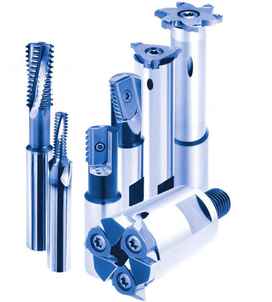
1 Your Partner For Clever Tooling Cutting Tools Manufacturer of Precision Tools Since 1974
2
3 mimatic GmbH Westendstraße Betzigau +49 (0) 831 / (0) 831 / * info@mimatic.de : 1


4 Our Company
5 Milling Thread Milling Extended program Face Finish Milling Notch Impact Test Gear Milling Extended program Slot Milling Contour and Radius Milling Chamfering, eburring Extended program Sawing, Slitting Sawing, Cutting, Slitting Extended program Bore Machining Reaming Axial Grooving Axial Grooving, adjustable Special Tools Special- and Combination Tools Cutting ata and Technical Information

6 Tool Systems for Highest emands Since 1974, we have been developing and producing cutting tools and driven tools for CNC machine tools. Our products are used in various fields of application for the machining industry for customers of the automotive industry, automotive suppliers, electrical engine-ering, vehicle construction, foundries, mechanical engineering and medical technology. The Allgäu region of Bavaria reputation reaches beyond its borders, because of its natural beauty, undisturbed nature and idyllic landscapes. It is also well known for its industrial power and innovative thinking in toolmaking and mechanical engineering. Our location in the Allgäu has a powerful production with all facilities of a modern industrial enterprise. 4


7 5


 Co.")
8 Locations Headquarter mimatic GmbH Westendstraße Betzigau Germany Tel Fax info@mimatic.de Research & evelopment Production Sales Service Subsidiaries Zettl mimatic Inc N Hillview Ct. Building 4 Mundelein IL USA Tel.: Ext Sales Service mimatic Tool Systems (Shanghai) Co.Ltd. Jinhui Road No.1688, Minhang istrict CN Shanghai China Tel.: Sales Service 6

9 Certificates CERTIFICATE The Certification Body of TÜV SÜ Management Service GmbH certifies that mimatic GmbH Westendstraße Betzigau Germany has established and applies a Quality Management System for evelopment, esign, Production, Sales and Service of riven Toolholders, Cutting Tools, Clamping Systems and Special Tools. An audit was performed, Report No Proof has been furnished that the requirements according to ISO 9001:2015 are fulfilled. The certificate is valid from until Certificate Registration No.: TMS. Product Compliance Management Munich, IN EN ISO 9001 : 2015 AEO F Authorized Economic Operator 7


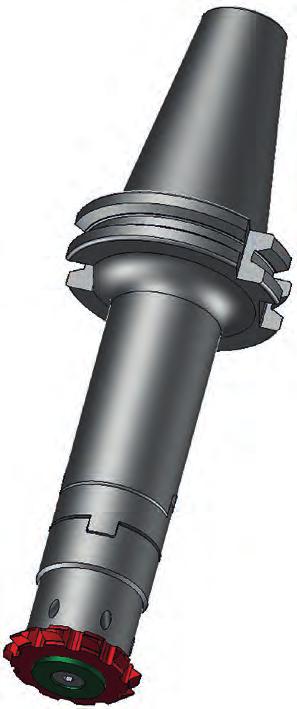
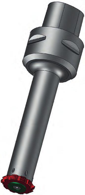
10 Products Cutting Tools Live Tools for Turning Machines Angle Heads for Milling Machines 8


11 Multi Spindle Units Clamping Technology Special Solutions 9


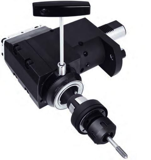
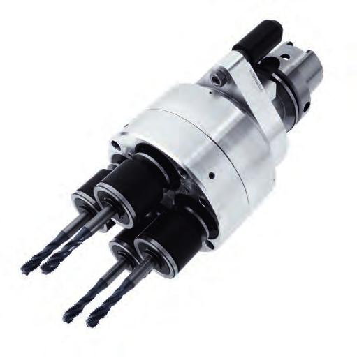
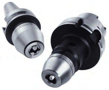
12 Economical Complete Machining with Live Tools Our boring and milling units are suitable for most of the popular turning machines and lathe equipment manufacturers. We produce the following types: Straight and offset units Internal or external coolant supply Gear multiplication or reduction Single or multi-spindle versions Angle heads for the production of angled holes, by means of adjustable and fixed angles Sawblade holders for sawing or slotting of workpieces Every popular type of tool system can be supplied 10 Technology and quality Highly precise bearing technology (high quality spindle and taper roller bearings) Specially optimized gears guarantee an excellently smooth run High torque transmission, rigidity and RPM`s Highest concentricity and facing accuracy < 3 µm Internal coolant supply up to 70 bar Use of high pressure seals und friction optimized special seals Additional labyrinth seals protect the bearings from the penetration of dirt and coolant Internal clamping nut guarantees a compact tool length and optimum bearing positioning ensures maximum axial and radial support at the spindle and high stability Alignment pins / blocks on angle units for minimum setup time and fine centreline adjustment Live tools are largely suitable for dry running The coolant filtering capabilities of the machine should be < 40 µm


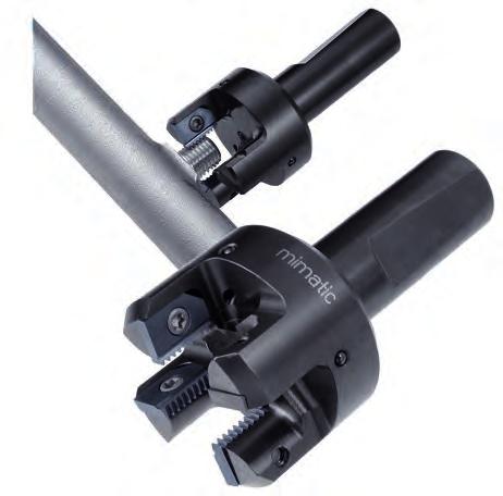
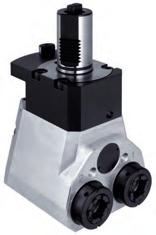
13 Angle Heads mimatic has been a reliable partner in project planning and the supply of precision tools worldwide for many years in the field of chip removing production. In addition to toolholding systems and cutting tools, the company also provides driven tools for both CNC lathes and CNC machining centers to solve customer-specific problems with chip removal. The company has provided many special purpose solutions of angle heads since its foundation in In doing so, mimatic has always placed special emphasis on maximum precision, power transmission, operating safety and quality. We ensure close cooperation with our customers worldwide, providing advice on all machining problems even on-site. We realize and implement our solutions on the basis of our comprehensive standard program or by means of customer-specific special developments and designs. Our program of angle head tools provides our customers with the means for complete, integrated machining. It is now no longer necessary to repeatedly relocate tools, which means a considerable reduction in production costs, rationalization and the increase in flexibility over the entire production process. 11
 The Revolutionary System eltimon (electronic live")


14 Free Your Tool Monitoring Innovations for Industry 4.0 (IIoT) The Revolutionary System eltimon (electronic live tool integrated monitoring) for igitization of Live Tools and Angle Heads Visualization using eltimon-app on your mobile phone ata storage in the eltimon-core in the live tool Synchronization through eltimon-cloud Real time analyses, trends and status Augmented operator, decision-support, reminders Maximum lifetime for your live tools 12

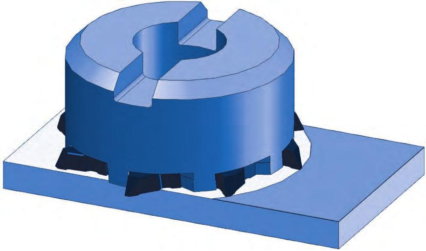
15 Turn Cut Milling Short processing times High process reliability Material saving High surface quality Absence of burrs Short chips Faster Parting Off Than Anybody Else! Turn Cut Milling Instead of Parting Off. 13

16 Thread Milling
17 Milling Thread Milling Extended program Face Finish Milling Notch Impact Test Gear Milling Extended program Slot Milling Contour and Radius Milling Chamfering, eburring Extended program Sawing, Slitting Sawing, Cutting, Slitting Extended program Bore Machining Reaming Axial Grooving Axial Grooving, adjustable Special Tools Special- and Combination Tools Cutting ata and Technical Information


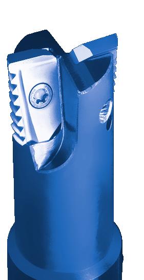
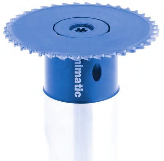
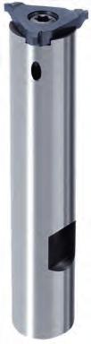
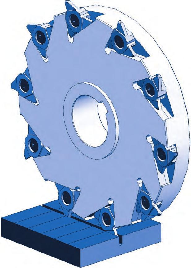
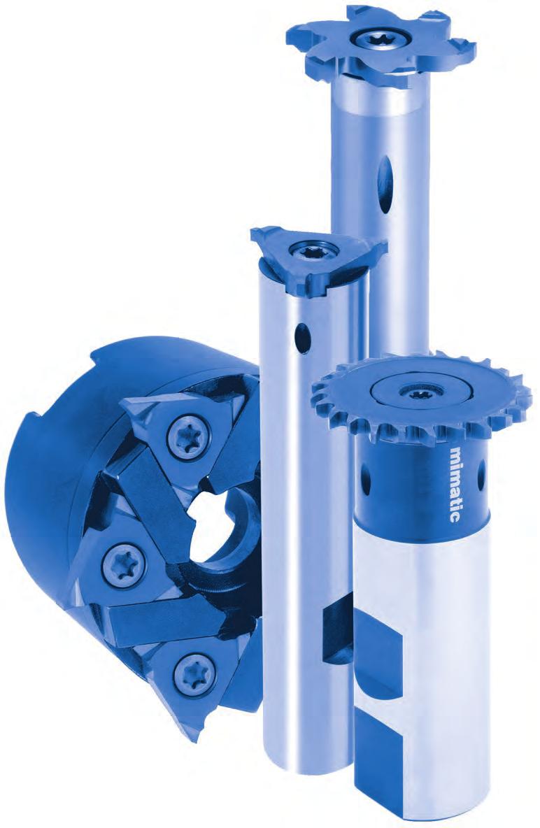
18 Thread Milling Systems for Circular Thread Milling Our bestseller system allows threading and / or circlip grooving in high precision. The polygonal connection of insert and milling body improves the efficiency and precision of the process significantly: Longer tool life Higher machining volume Higher feed rates Shorter processing times High stability High security at interrupted cutting Affordable and flexible system for short processing times and long tool lifes. eep, true to gauge threads Accurate free-form contours Accurate grooving Bottom threads can be cut almost to the bottom without undercuts. By using the same pitches, the storage and acquisition costs decrease also. Smooth cutting and low cutting pressure results in high surface quality and long tool lifes. A conical position of insert pocket guarantees stability of the tool shaft. Further advantages are the radially back ground thread profile, extremely high wedge angle, a more stable cutting edge as well as a positive rake angle. The optimum application area are fine threads and/or very short thread lengths. Thread milling with undercut Thread milling rill thread milling Extensive range of solid carbide thread milling cutters. Spiral-grooved grooves Soft cut Excellent surface qualities Also for thin-walled workpieces A tool for right- and left-hand threads Unbeatable in price / performance 14, Multi tooth thread milling cutters, ideal for short thread lengths and very rigid clamping of workpiece and cutter. Sectional thread milling for high-quality large threads from M24. STC-1 with 10 edges Biggest advantage for any long threads from M24: A shorter process time compared to cutters with inserts and easier assembly. STC-2 and STC-3 epending on the thread length (pitch, material) much faster than STC-1. 16
19 Thread Milling Symbols 1 Trio-Cut 12 Type designation M Thread standard IN 1835 Form A shaft without clamping surface M Thread with undercut (Trio-Cut) IN 1835 Form B shaft with Weldon clamping surface IR / IL for right- and left hand internal thread for left hand thread modify your NC-program! IN 6535 Form A Solid carbide shaft without clamping surface AR / AL for right- and left hand external thread for left hand thread modify your NC-program! IN 6535 Form B Solid carbide shaft with Weldon clamping surface Full form Full form thread milling Partial form Partial form thread milling Cutter with tightening thread 60 Point angle Ø min. 8 Smallest necessary bore-diameter Internal coolant supply IN 13 Thread standard of inserts Short escriptions Alpha (α) Point angle of milling insert A Groove width A1 Basic width in the Groove B f6 Insert holder width of axial grooving tool B H7 Groove width of axial grooving tool B W Tool width of axial grooving tool C Chamfer width Cutting diameter d1 Milling body diameter (front) d2 Large diameter of milling body d g6 Fitting face diameter of threaded milling tool h6 Shaft diameter of milling body (Arbor) P Flight circle of insert R Nominal diameter of concave radius insert E Width blank insert F H P H S L L1 L2 L G L HA L P1 L P2 L PF L S M P R Width of trailing chamfer Insert height Slider height (Axial grooving tool) Lenght of milling tool Clamping lenght of milling tool Lenght of step milling head Usable thread length at the multi-tooth thread milling Holder lenght Insert height of milling body edge Insert height of edge interfering contour Lenght of fitting face Shaft lenght clamping lenght (epth) Thread size Pitch Radius (general/ coon) Formula for Tool Lengths L WKZ = L GK + L 1 + L P1 (+L P2 ) 17


20 Thread Milling Table of Contents Thread Inserts M, MF, UN, NPT, NPSM G, BSW, BSF, UNC, UNF, UNEF, Rp Tr, ACME, Rd UNEF thread Tool Holders with cylindrical shank for driven toolholders with tightening shank Thread Inserts M, MF UN, NPT, NPSM G, BSW, BSF, UNC Tool Holders with cylindrical shank with tightening shank Thread Inserts M, MF UN, NPT, NPSM G, BSW, BSF Tool Holders Type 023 Type Thread Inserts M G, BSW, BSF PG Tool Holders Type 12 Type Thread Inserts M G, BSW, BSF Tool Holders Type 20 Type 25 Typ 50 /
21 Thread Milling Table of Contents 1 14, Thread Inserts M G, BSW, BSF UNC, UNF PG Tool Holders Type 14,5 Type 15 Type 21 Type , Thread Inserts M G, BSW, BSF UNC, UNF PG Tool Holders Type 14,5 Type 15 Type Solid Thread Milling Cutter M MF G BSW BSF UNC UNF NPT, NPTF STC Thread Milling System M24 M30 M36 M42 M48 M56 M64 M64 tap hole Ø 20, , , Also as MF, UN, UNC, NPSM Technical ata Notes to the circular thread milling Prograing example TrioCUT Cutting data values grades
22 Thread Milling Thread Milling Insert holder see page Cutting data see page 173 M Full form MF IN 60 IR / IL 13 Typ Pitch L P1 L P2 t Thread of teeth P12 P16 P20 P25 P1210 * 1,00 9,6 2,65 0,80 0,572 M14 x P1210 * 1,50 9,6 2,50 0,95 0,875 M16 x 1, P1210 * 1,75 9,6 2,25 1,20 1,010 only M P1211 * 2,00 10,5 2,25 1,20 1,127 only M14, M P1211 * 2,00 10,5 2,25 1,20 1,157 M20 x P1616 1,00 16,0 2,80 1,03 0,572 M20 x P1616 1,50 16,0 2,55 1,28 0,864 M24 x 1, P1616 2,00 16,0 2,55 1,28 1,157 M26 x P1616 2,50 16,0 2,05 1,78 1,444 M30 x 2, P1616 2,50 16,0 2,05 1,78 1,400 only M P1616 3,00 16,0 3,05 1,78 1,702 M32 x P2020 1,50 20,0 2,55 1,28 0,875 M26 x 1, P2020 2,00 20,0 2,55 1,28 1,157 M30 x P2020 3,00 20,0 2,15 1,68 1,745 only M P2526 1,50 26,0 2,15 1,28 0,875 M34 x 1, P2526 2,00 26,0 2,55 1,28 1,159 M38 x P2526 3,00 26,0 2,95 1,88 1,702 M45 x P2524 3,50 24,0 2,75 2,08 1,960 only M P2526 3,50 26,0 2,90 1,93 1,980 M50 x 3, P2526 4,00 26,0 2,90 1,93 2,262 M52 x P2526 4,00 26,0 2,65 2,18 2,262 only M P2526 4,50 26,0 2,65 2,18 2,602 M56 x 4, P2526 5,00 26,0 3,85 3,48 2,836 M62 x P2526 5,50 26,0 3,85 3,48 3,182 M68 x 5, P2526 6,00 26,0 3,85 3,48 3,467 M72 x External thread according to IN 13 on request M MF UN NPT NPSM 60 IR / IL AR / AL Partial form Type Pitch L P1 L P2 G of teeth 20 P12 P ,7 2,125 1,33 0, P16 P20 P25 P1616 ** ,0 2,70 1,68 0, P1616 ** 2,5-4 16,0 2,70 1,68 0, P ,7 2,70 1,05 0, P ,0 2,15 1,68 0, P ,7 4,15 1,00 0, P ,7 2,95 1,80 0, P ,0 2,75 2,08 0, P2526 2,5-5 26,0 2,65 2,18 0, P2526 3,5-6 26,0 3,85 2,93 0, * Not suited for cutter ** Not suited for pitch 4,0 with the cutters and
23 Thread Milling Thread Milling 1 Insert holder see page Cutting data see page 173 Conditional deliverable Further sizes on request BSW IR / IL BS 84 Full form 55 Type Pitch Pitch / " L P1 L P2 t Thread of teeth P12 P16 P20 P25 P1210 * 2, ,25 1,1 1,371 BSW ⁹ ¹⁶ P1210 * 2, ,4 2,15 1,5 1,494 BSW ⅝ + ¹¹ ¹⁶ P1212 * 2, ,7 2,2 1,4 1,455 BSW ¾ + ¹³ ¹⁶ P1616 2, ,15 1,675 1,622 BSW ⅞ + ¹⁵ ¹⁶ P1616 3, ,65 1,84 1,83 BSW P1616 ** 3, ,65 2,05 2,098 BSW 1⅛ + 1¼ P1616 ** 4, ,175 2,2 2,455 BSW 1⅜ + 1½ P2020 3, ,7 2,225 2,098 BSW 1⅛ + 1¼ P2020 *** 4, ,15 2,675 2,455 BSW 1⅜ + 1½ P2524 4, ,4 2,675 2,455 BSW 1⅜ P2524 4, ,4 2,675 2,455 BSW 1½ P2524 5, ,9 2,875 2,955 BSW 1⅝ + 1¾ BSF IR / IL BS 84 Full form 55 Type Pitch Pitch / " L P1 L P2 t Thread of teeth P12 P16 P20 P25 P1210 * 1, ,6 2,25 1,1 1,177 BSF ⅝ + ¹¹ ¹⁶ P1210 * 2, ,25 1,1 1,371 BSF ¾ + ¹¹ ¹⁶ P1210 * 2, ,4 2,15 1,5 1,494 BSF ⅞ P1212 * 2, ,7 2,20 1,4 1,455 BSF P1616 2, ,15 1,675 1,622 BSF 1⅛ + 1¼ P1616 3, ,15 1,675 1,83 BSF 1⅜ - 1⅝ P1616 ** 3, ,65 2,05 2,098 BSF 1¾ P1616 ** 4, ,175 2,2 2,455 BSF 2¼ - 2¾ P2020 3, ,15 1,675 1,83 BSF 1⅜ - 1⅝ P2020 3, ,7 2,225 2,098 BSF 1¾ P2020 *** 4, ,15 2,675 2,455 BSF 2¼ - 2¾ P2524 3, ,1 1,675 1,83 BSF 1⅜ - 1⅝ P2524 3, ,65 2,175 2,098 BSF 1¾ P2524 4, ,4 2,675 2,455 BSF 2¼ - 2¾ P2524 5, ,9 2,875 2,955 BSF 3-3¼ External thread BSW / BSF see next page * Not suited for cutter ** Not suited for cutters and *** Not suited for cutter

24 Thread Milling Thread Milling Insert holder see page Cutting data see page 173 Conditional deliverable Further sizes on request BSW BSF BS AR / AL Full form Type Pitch Pitch / " L P1 L P2 t Thread of teeth P12 P16 P20 P25 P1212 * 1, ,7 2,30 1,3 1,178 BSW / BSF - 14 Gg P1212 * 2, ,7 2,25 1,4 1,374 BSW / BSF - 12 Gg P1212 * 2, ,7 2,25 1,4 1,498 BSW / BSF - 11 Gg P1212 * 2, ,7 2,25 1,4 1,646 BSW / BSF - 10 Gg P1616 1, ,15 1,675 1,178 BSW / BSF - 14 Gg P1616 2, ,15 1,675 1,374 BSW / BSF - 12 Gg P1616 2, ,75 2,075 1,498 BSW / BSF - 11 Gg P1616 2, ,15 1,675 1,646 BSW / BSF - 10 Gg P1616 2, ,15 1,675 1,829 BSW / BSF - 9 Gg P1616 ** 3, ,65 1,820 2,056 BSW / BSF - 8 Gg P1616 ** 3, ,15 2,225 2,348 BSW / BSF - 7 Gg P1616 ** 4, ,15 2,225 2,737 BSW / BSF - 6 Gg P2020 1, ,10 1,725 1,178 BSW / BSF - 14 Gg P2020 2, ,10 1,725 1,374 BSW / BSF - 12 Gg P2020 2, ,10 1,725 1,498 BSW / BSF - 11 Gg P2020 2, ,10 1,725 1,646 BSW / BSF - 10 Gg P2020 2, ,10 1,725 1,829 BSW / BSF - 9 Gg P2020 *** 3, ,65 2,175 2,056 BSW / BSF - 8 Gg P2020 *** 3, ,65 2,175 2,348 BSW / BSF - 7 Gg P2020 *** 4, ,15 2,675 2,737 BSW / BSF - 6 Gg P2526 2, ,75 2,075 1,478 BSW / BSF - 11 Gg P2526 3, ,60 2,175 2,056 BSW / BSF - 8 Gg P2526 3, ,60 2,175 2,348 BSW / BSF - 7 Gg P2524 4, ,40 2,675 2,737 BSW / BSF - 6 Gg P2524 **** 5, ,40 2,675 3,281 BSW / BSF - 5 Gg G IN BSW 228/1 BSF 55 IR / IL AR / AL Partial form Type Pitch Pitch / " L P1 L P2 r S max. of teeth P16 P1616 1,814-3, ,75 1,625 0,35 2, P25 P2526 3,175-6, ,65 2,175 0,6 2, Taper pipe thread BSPT according to BS.84 on request * Not suited for cutter ** Not suited for cutters and *** Not suited for cutter **** Not suited for cutter
25 Thread Milling Thread Milling 1 Insert holder see page Cutting data see page 173 Conditional deliverable Further sizes on request G IR / IL IN 228/1 Full form Rp ISO Type Pitch Pitch / " L P1 L P2 t Thread of teeth P12 P16 P20 P25 P1210 * 1, ,6 2,25 1,2 0,871 G ¼ P1210 * 1, ,6 2,25 1,2 0,871 G ⅜ P1212 * 1, ,7 2,25 1,2 1,177 G ½ - G ⅞ P1212 * 2, ,7 2,15 1,5 1,319 G 1 - G P1616 1, ,15 1,675 1,177 G ½ - G ⅝ P1616 1, ,15 1,675 1,177 G ¾ - G ⅞ P1616 2, ,75 2,075 1,949 G 1 - G P2020 1, ,95 1,725 1,177 G ¾ - G ⅞ P2020 2, ,95 1,725 1,949 G 1 - G P2526 2, ,15 1,675 1,949 G 1 - G 1¼ P2526 2, ,75 2,075 1,949 G 1½ - G G AR / AL IN 228/1 Full form 55 Type Pitch Pitch / " L P1 L P2 t Thread of teeth P1210 * 1, ,6 2,25 1,2 0,871 G ¼ - G ⅜ P12 P1212 * 1, ,7 2,3 1,1 1,178 G ½ - G ⅞ P1212 * 2, ,7 2,25 1,2 1,498 G 1 - G P1616 1, ,15 1,675 1,177 G ½ - G ⅞ P16 P1616 2, ,75 2,075 1,478 G 1 - G P1618 1, ,7 3,15 0,95 1,177 G ½ - G ⅞ P20 P2020 1, ,95 1,725 1,177 G ½ - G ⅞ P2020 2, ,95 1,725 1,478 G 1 - G P25 P2526 2, ,75 2,075 1,478 G 1 - G Taper pipe thread R according to ISO on request * Not suited for cutter
26 Thread Milling Thread Milling Insert holder see page Cutting data see page 173 UNC IR / IL ASME 1.1 Full form 60 Type Pitch Pitch / " L P1 L P2 t Thread of teeth P1210 * 1, ,25 1,2 1,10 UNC ½ P12 P1210 * 2, ,25 1,2 1,29 UNC ⁹ ¹⁶ P1211 * 2, ,5 2,13 1,52 1,35 UNC ⁵ ⁶ P1212 * 2, ,7 2,13 1,52 1,485 UNC ¾ P16 P1616 2, ,05 1,775 1,577 UNC ⅞ P20 P2018 ** 3, ,65 2,175 1,809 UNC P2020 ** 3, ,65 2,175 2,043 UNC 1⅛ - 1¼ P2524 4, ,05 3,275 2,454 UNC 1⅜ - 1½ P25 P2526 5, ,85 3,475 2,979 UNC 1¾ P2526 *** 5,644 4,5 26 3,85 3,475 3,289 UNC 2-2¼ - 4½ UNF IR / IL ASME 1.1 Full form 60 Type Pitch Pitch / " L P1 L P2 t Thread of teeth P1210 * 1, ,6 2,5 0,95 0,733 UNF ½ P12 P1211 * 1, ,5 2,5 0,95 0,827 UNF ⁹ ¹⁶ P1212 1, ,7 2,5 0,95 0,945 UNF ¾ P16 P1618 1, ,7 3,15 0,95 1,071 UNF ⅞ P20 P2020 2, ,15 1,675 1,228 UNF Article conditioned on stock UNEF IR / IL ASME 1.1 Full form 60 Type Pitch Pitch / " L P1 L P2 t Thread of teeth P12 P1210 * 0, ,6 2,5 0,95 0,556 UNEF ⁷ ¹⁶ - ½ P1212 1, ,7 2,5 0,95 0,649 UNEF ⁹ ¹⁶ - ¹¹ ¹⁶ P16 P1616 1, ,05 1,775 0,779 UNEF ¾ P20 P2020 1, ,15 1,675 0,865 UNEF 1¹ ¹⁶ - 1¹¹ ¹⁶ * Not suited for cutter ** Not suited for cutter *** Not suited for cutter
27 Thread Milling Thread Milling 1 Insert holder see page Cutting data see page 173 Article conditioned on stock Tr IR / IL IN 103 Full form 30 Typ Pitch L P1 L P2 t Thread Chip angle of teeth P12 P16 P25 P1210 * 1,5 9,6 2,775 0,575 0,9 Tr 14x1, P1210 * 1,5 9,6 2,775 0,575 0,9 Tr 20x1, P1212 * 2,0 11,7 2,5 1,1 1,25 Tr 16x2 - Tr 20x P1211 * 3,0 11,0 2,23 1,42 1,75 Tr 18x3 - Tr 20x P1212 * 4,0 12,0 2,15 1,5 2,25 Tr 20x P1614 ** 3,0 14,0 2,3 1,5 1,75 TR 24x3 - Tr 32x P1615 ** 5,0 15,3 3,0 2,25 2,75 Tr 24x P1615 ** 5,0 15,3 3,15 2,1 2,75 Tr 26x P1615 ** 5,0 15,3 3,15 2,1 2,75 Tr 28x5 - Tr 36x P1616 ** 6,0 16,2 4,27 3,0 3,5 Tr 30x6 - Tr 32x P1616 ** 6,0 16,2 4,22 3,03 3,5 Tr 34x6 - Tr 42x P2524 3,0 24,0 2,6 2,1 1,75 Tr 36x3 - Tr 40x P2524 4,0 24,0 1,85 2,0 2,25 Tr 65x P2525 5,0 25,0 3,2 2,37 2,75 Tr 44x5 - Tr 48x P2522 *** 7,0 22,0 4,0 2,65 3,75 Tr 38x7 - Tr 42x P2522 *** 7,0 22,0 4,0 2,65 3,75 Tr 44x P2525 *** 8,0 25,0 4,75 3,4 4,5 Tr 46x8 - Tr 48x P2525 *** 8,0 25,0 5,03 3,13 4,5 Tr 50x8 - Tr 52x P2525 *** 9,0 25,0 4,73 3,42 4,75 Tr 55x9 - Tr 60x P2525 *** 10,0 25,0 4,65 3,5 5,25 Tr 65x10 - Tr 80x Tr AR / AL IN 103 Full form 30 Typ Pitch L P1 L P2 t Thread Chip angle of teeth P12 P16 P25 P1210 * 1,5 9,6 2,775 0,575 0,90 Tr 8x1,5 External P1212 * 2,0 11,7 1, On request P1212 * 3,0 11,7 1, On request P1212 * 4,0 11,7 2, On request P1616 ** 3,0 16,0 1,75 8 / 6 3 / 6 On request P1616 ** 4,0 16,0 2,4 1,63 2,25 Tr 16x4 External P1616 ** 5,0 16,0 2,75 8 / 6 3 / 6 On request P1616 ** 6,0 16,0 3,25 8 / 6 3 / 6 On request P2525 4,0 25 / 26 2,25 8 / 6 3 / 6 On request P2525 *** 5,0 25 / 26 2,75 8 / 6 3 / 6 On request P2525 *** 6,0 25 / 26 3,75 8 / 6 3 / 6 On request P2525 *** 7,0 25 / 26 3,75 8 / 6 3 / 6 On request P2525 *** 8,0 25 / 26 4,25 8 / 6 3 / 6 On request P2525 *** 9,0 25 / 26 4,75 8 / 6 3 / 6 On request P2525 *** 10,0 25 / 26 5,25 8 / 6 3 / 6 On request * Not suited for cutter ** Not suited for cutters and *** Not suited for cutters , and
28 Thread Milling Thread Milling Insert holder see page Cutting data see page 173 Conditional deliverable Further sizes on request ACME IR / IL ASME 1.1 Full form 29 Typ Pitch Pitch / " L P1 L P2 t Thread Chip angle of teeth P16 P25 P1616 5, ,02 2,23 2,85 1" - 5 Gg - 1⅛" - 5 Gg P1616 * 6, ,04 3,21 3,43 1¼" - 4 Gg - 1½"-4 Gg P2524 6, ,9 2,75 3,47 1¾" - 4 Gg - 2" - 4 Gg P2525 8, ,65 3,5 4,51 2¼" - 3 Gg - 2¾" - 3 Gg Rd IR / IL IN 405 Full form 30 Typ Pitch Pitch / " L P1 L P2 t Thread Chip angle of teeth P16 P1613 * 3, ,15 2,1 1,588 Rd 20 x ⅛ P1614 * 3, ,15 2,1 1,588 Rd 22 x ⅛ P1615 * 3, ,4 1,9 1,588 Rd 24 x ⅛ - Rd 26 x ⅛ P1616 3, ,4 1,9 1,588 Rd 28 x ⅛ - Rd 32 x ⅛ P1616 3, ,4 1,9 1,588 Rd 34 x ⅛ - Rd 38 x ⅛ P1616 * 4, ,15 2,575 2,117 Rd 40 x ¹ ⁶ - Rd 55 x ¹ ⁶ P1616 * 4, ,15 2,575 2,117 Rd 58 x ¹ ⁶ - Rd 80 x ¹ ⁶ P1616 * 4, ,15 2,575 2,117 Rd 82 x ¹ ⁶ - Rd 100 x ¹ ⁶ P1616 * 6, ,15 3,125 3,175 Rd 105 x ¼ - Rd 200 x ¼ Rd IR / IL IN 405 Full form 30 Typ Pitch Pitch / " L P1 L P2 t Thread Chip angle of teeth P16 P1616 3, ,65 2 1,588 Rd 28 x ⅛ P2526 4, ,85 3,4 2,117 Rd 65 x ¹ P25 ⁶ P2526 6, ,85 3,4 3,175 Rd 105 x ¼ - Rd 120 x ¼ Knuckle thread acc. to IN on request * Not suited for cutters and
29 Thread Milling Circular Milling Tools with Polygonal Insert Seat 1 Inserts see page Cutting data see page 173 IN 1835 Form A IN 1835 Form B IN 6535 Form A IN 6535 Form B Spare part No. S max. d h6 d1 max. L L1 L2 Type Form (-d1)/2 Shaft Screwdriver * Screw * B 12 7,0 11,7 2,35 67, B 12 7,0 11,7 2,35 67, P A 12 7,0 11,7 2,35 67, B 12 7,0 11,7 2, A 12 7,0 11,7 2, T8 IP M2,5x B 12 7,0 11,7 2, A 12 7,0 11,7 2, B 12 9,0 17,7 4,35 67, B 12 9,0 17,7 4,35 67, A 12 9,0 17,7 4,35 67, P B 12 9,0 17,7 4,35 82, A 12 9,0 17,7 4,35 82, T8 IP M3x A 12 9,0 17,7 4, A 12 11,5 17,7 2,85 82,4 37, A 12 12,0 17,7 2,85 122,5 77, B 16 11,5 21,7 5, P B 16 11,5 21,7 5, A 16 11,5 21,7 5, B 16 11,5 21,7 5, T15 IP M4x A 16 11,5 21,7 5, A 16 15,5 21,7 3,1 105,5 57, B 16 13,6 27,7 7,05 79,6 30, B 16 13,6 27,7 7,05 79,6 30, A 16 13,6 27,7 7,05 79,6 30, B 16 13,6 27,7 7,05 94,6 45,5 - P A 16 13,6 27,7 7,05 94,6 45, B 16 13,6 27,7 7,05 109,6 60,5 - T20 IP M5x13, A 16 13,6 27,7 7,05 109,6 60, A 16 15,5 27,7 6, , A 16 15,5 27,7 6,1 149,5 101,5 21, A 20 15,5 27,7 6,1 174,45 128,5 21,5 * Screwdriver and clamping screw included in delivery Screw torques max T08 IP 1,0 Nm T08 IP 1,1 Nm T15 IP 3,8 Nm T20 IP 5,5 Nm 27
30 Thread Milling Circular Milling Tools for riven Toolholders Inserts see page Cutting data see page 173 Form A Form ER IN 1835 Form A IN 6499 Spare part No. S max. d h6 d1 max. L L1 Type Form (-d1)/2 Shaft Screwdriver * Screw * P A 10 7,0 11,7 2, ER 16 7,0 11,7 2,35 37, ER 20 7,0 11,7 2, T8 IP M2,5x P A 10 9,0 17,7 4, ER 16 9,0 17,7 4,35 41, ER 20 9,0 17,7 4, T8 IP M3x P A 12 11,5 21,7 5,1 62,4 14, ER 20 11,5 21,7 5,1 49,5 14, ER 25 11,5 21,7 5, ,4 T15 IP M4x P A 16 13,6 27,7 7,05 69,6 20, ER 25 13,6 27,7 7, ,4 T20 IP M5x13, ER 32 13,6 27,7 7, ,4 Screw torques max T8 IP 1,0 Nm T8 IP 1,1 Nm T15 IP 3,8 Nm T20 IP 5,5 Nm Changing Inserts Clamp cutter before changing insert. Loosen insert screw. Remove used insert and clean the insert pocket before clamping new insert. Please use the appropriate TIP hex key for the tighening of the inserts and consider the screw tightening torques in the tables. * Screwdriver and clamping screw included in delivery 28
31 Thread Milling 1 Circular Milling Tools with Polygonal Insert Seat Inserts see page Cutting data see page 173 Form A Form B Please adapt cutting data to overhangs length Spare part No. Type Form d1 d2 max. S max. (-d1)/2 L L1 M d g6 L PF Screwdriver * Screw * P12*** B 9,5 11,7 1,1 13,5 M5 5,5 5, P A 9,0 14,4 17,7 4,35 29,5 19,5 M8 8,5 5, P16** B 9,5 17,7 4,1 18,5 M5 5,5 5, P16*** B 11,0 17,7 3,35 18,5 M6 6,5 5, P A 11,5 18,0 21,7 5,1 35,0 25,0 M10 10,5 5, P20** B 11,5 21,7 5,1 20,5 M6 6,5 5, P20*** B 13,5 21,7 4,1 20,5 M8 8,5 5, P A 13,6 22,5 27,7 7,05 42,5 29,5 M12 12,5 5, P25** B 13,6 27,7 7,05 22,6 M8 8,5 5, P25*** B 18,0 27,7 4,85 22,6 M10 10,5 5, * Screwdriver and clamping screw included in delivery ** Slim design for thread milling *** Reinforced design Screw torques max T8 IP 1,0 Nm T8 IP 1,1 Nm T15 IP 3,8 Nm T20 IP 5,5 Nm Assembling Instructions Recoended tightening torque for screw-in circular milling body End-wrench see page 157 Thread size (M) Wrench size Tightening torque Nm M5 7 8 M M M M M
32 Thread Milling Thread Milling Insert holder see page 32 Cutting data see page 173 M IR / IL MF IN 13 Full form 60 Type Pitch IC L P1 L P2 t Thread ,0 10,6 5,5 1,64 0,7 0,578 M12x ,5 10,6 5,5 1,39 0,95 0,864 M14x1, ,0 10,6 5,5 2,0 1,0 1,159 M16x ,0 17,5 9,2 2,8 0,7 0,578 M20x ,5 17,5 9,2 2,55 0,95 0,864 M24x1, ,0 17,5 9,2 2,3 1,2 1,159 M30x ,5 17,5 9,2 2,05 1,45 1,444 M32x2, ,5 16,0 9,2 1,75 1,75 1,444 only M ,0 17,5 9,2 2,1 1,4 1,728 M42x ,0 23,0 12,4 3,3 0,7 0,578 M30x ,5 23,0 12,4 3,05 0,95 0,864 M32x1, ,0 23,0 12,4 2,8 1,2 1,159 M36x ,5 23,0 12,4 2,55 1,45 1,444 M38x2, ,0 23,0 12,4 2,3 1,7 1,728 M42x ,5 23,0 12,4 2,3 1,7 2,023 M48x3, ,0 23,0 12,4 2,3 1,7 2,308 M50x ,5 23,0 12,4 4,0 2,5 2,602 M50x4, ,0 23,0 12,4 4,0 2,5 2,887 M52x ,5* 23,0 12,4 3,6 2,9 3,182 M ,0* 23,0 12,4 3,2 3,3 3,467 M M MF UN NPT NPSM 60 IR / IL AR / AL Partial form Type Pitch IC L P1 L P2 G t max ,0 10,6 5,5 1,5 1,5 0,1 1, ,5 17,5 9,2 1,59 1,91 0,1 2, ,0 23,0 12,4 1,85 2,15 0,1 2, * Not suited for cutters , and

33 Thread Milling Thread Milling 1 Insert holder see page 32 Cutting data see page 173 G 55 IN BSW BSF 228/1 IR / IL AR / AL Full form Type Pitch Pitch / " IC L P1 L P2 t Thread 03 1,337 * 19 10,6 5,5 1,25 1,09 0,871 G ¼" , ,6 5,5 1,25 1,09 0,871 G ⅜" ,814 * 14 16,0 9,2 1,75 1,75 1,162 G ½" , ,5 9,2 2,2 1,3 1,162 G ¾" , ,5 9,2 1,9 1,6 1,494 G 1" , ,5 9,2 1,75 1,75 1,830 BSW 1" , ,5 9,2 1,75 1,75 1,830 BSW 1⅜ - 1 ⅝" , ,0 12,4 2,4 1,6 1,494 G 1" UNC IR / IL ASME 1.1 Full form 60 Type Pitch Pitch / " IC L P1 L P2 t Thread 03 1, ,0 5,5 1,17 1,17 1,099 UNC ½ " ,309 ** 11 10,6 5,5 1,17 1,17 1,349 UNC ⅝ " ,540 ** 10 10,6 5,5 1,17 1,17 1,470 UNC ¾" Request Form for Tread Milling Please download our fillable PF form for a detailed thread milling request and fax or send us back via mimatic.de Request form: * Only for external threads ** Not suited for cutters
34 Thread Milling Circular Milling Tools Inserts see page Cutting data see page 173 IN 1835 Form A IN 1835 Form B IN 6535 Form A IN 6535 Form B Ø min. 11 S max. 3,45 Spare part No. IC d h6 d1 S max. L L1 Type Form Shaft Screwdriver * Screw * ** B 10,6 5,5 10 7,4 1,6 57,2 17, ** B 10,6 5,5 12 7,4 1,6 64,66 17, ** A 10,6 5,5 12 7,4 1,6 64,66 17,2 T6 IP B 10,6 5,5 10 7,4 1,6 74,2 34, A 10,6 5, ,25 77,66 41, B 17,5 9, ,6 74,05 28, B 17,5 9, ,6 78,6 28, A 17,5 9, ,6 78,6 28, B 17,5 9, ,6 108,7 63,7 T15 IP A 17,5 9, ,6 79,3 34, A 17,5 9, ,6 96,5 51, A 17,5 9, ,6 121,5 76, B 23,0 12, ,45 87,0 38, B 23,0 12, ,45 116,0 67, *** A 23,0 12, ,0 93,0 41, A 23,0 12, ,0 137,0 88, B 23,0 12, ,0 137,0 88,5 T20 IP A 23,0 12, ,45 111,0 63, A 23,0 12, ,45 148,5 100,0 ** Without internal coolant supply *** Also suitable as basic body for a tandem cutter. Tightening torques see page 29 Screw torques max T6 IP 0,9 Nm T15 IP 3,8 Nm T20 IP 5,5 Nm Ø min. 11 S max. 3,45 Please adapt cutting data to overhangs length Spare part No. Type IC d g6 d1 d2 S max. L L1 M Screwdriver * Screw * ,6 5,5 6,5 7,4 10,0 1,60 22,66 13, ,5 9,2 8,5 12,2 15,4 2,60 27,5 18, ,0 12,4 10,5 16,1 18,0 3,45 32,0 29, * Screwdriver and clamping screw included in delivery 32 Screw torques max T6 IP 0,9 Nm T15 IP 3,8 Nm T20 IP 5,5 Nm
35 Thread Milling Thread Milling 1 Insert holder see page Cutting data see page 173 M MF IN 13 Typ 023 Typ 013 IR / IL Full form 60 Type Pitch P IC L P1 L P2 t ,5 17,5 9,2 4,08 0,95 0, ,0 17,5 9,2 3,83 1,2 1, ,5 17,5 9,2 3,52 1,51 1, ,0 17,5 9,2 3,33 1,7 1, ,0 17,5 9,2 2,63 2,4 2, ,5* 17,5 9,2 2,53 2,5 2, ,0* 17,5 9,2 2,13 2,9 2, ,5* 17,5 9,2 2,7 3,33 3, ,0* 17,5 9,2 2,7 3,33 3, ,5 23,0 12,4 5,58 0,95 0, ,0 23,0 12,4 5,33 1,2 1, ,5 23,0 12,4 5,02 1,51 1, ,0 23,0 12,4 4,83 1,7 1, ,5 23,0 12,4 4,83 1,7 2, ,0 23,0 12,4 4,63 1,9 2, ,5 23,0 12,4 4,03 2,5 2, ,0 23,0 12,4 4,03 2,5 2, ,0 23,0 12,4 3,23 3,3 3, ,0 23,0 12,4 3,454 3,941 4, M MF UN NPT NPSM Typ 023 Typ 013 IR / IL AR / AL Partial form 60 Type Pitch P IC L P1 L P2 G S max ,5 17,5 9,2 3,28 1,75 0,10 2, ,0* 17,5 9,2 2,7 3,33 0,25 3, ,0 23,0 12,4 4,88 1,65 0,10 2, ,5 6 23,0 12,4 2,8 3,73 0,40 4, * Not suited for cutters


36 Thread Milling Thread Milling Insert holder see page Cutting data see page 173 G IN BSW BSF 228/1 Typ 023 Typ 013 IR / IL AR / AL Full form 55 Type Pitch Pitch / " P IC L P1 L P2 t 023 2, ,5 9,2 3,33 1,7 1, , ,0 12,4 4,14 2,39 1, Circular Milling Tools Inserts see page Cutting data see page 173 Typ 023 Ø min. 33 IN 1835 Form B S max. 2,6 IC 9,2 Spare part No. T15 IP d h6 d1 S max. L HA L L1 Inserts Shaft Screwdriver * Screw * ,8 2,6 124,2 119,97 61, Screw torque max. 3,8 Nm
37 Thread Milling 023 Circular Milling Tools 1 Inserts see page Cutting data see page 173 Tightening torques see page 29 Please adapt cutting data to overhangs length Typ 023 IC 9,2 Ø min. 33 S max. 3,4 Spare part No. T15 IP d g6 d1 S max. L HA L Inserts M Screwdriver * Screw * ,5 24,3 3, ,97 3 M Screw torque max. 3,8 Nm Assembly instruction see page 182 Typ 023 IC 9,2 Ø min. 40 S max. 4,0 Accessories Spare part No. d H6 d1 S max. L HA L B MN Inserts Key T15 IP Screwdriver * Screw * ,4 45,3 40,97 8, * ,9 39,3 34,97 10, * ,0 39,3 34,97 12, Screw torque max. 3,8 Nm * Cutter clamping screw internal hexagon * Screwdriver and clamping screw included in delivery 35
38 Thread Milling 013 Circular Milling Tools Inserts see page Cutting data see page 173 Typ 013 IC 12,4 Ø min. 65 S max. 6,0 Spare part No. T20 IP d H6 d1 S max. L HA L B MN Inserts Screwdriver * Screw * ,5 37,5 12, Screw torque 5,5 Nm Cutter clamping screw internal hexagon Typ 013 IC 12,4 Ø min. 95 S max. 6,0 Spare part No. T20 IP d H6 d1 S max. L HA L B MN Inserts Screwdriver * Screw * ,2 33,5 14, Screw torque 5,5 Nm Typ 013 IC 12,4 Ø min. 95 S max. 6,0 Spare part No. T20 IP d H6 d1 S max. L HA L B MN Inserts Screwdriver * Screw * ,0 39,2 33,5 14, * Screwdriver and clamping screw included in delivery 36 Screw torque 5,5 Nm
39 Thread Milling Circular Milling Tools 1 Inserts see below Cutting data see page 173 Trio-Cut 12 IN 1835 Form B Ø min. 14 Spare part No. T8 IP d h6 d1 L L1 Shaft Screwdriver * Screw * , Screw torque max. 1,1 Nm Circular Milling Inserts Note: Type 12 milling tools can only be used with type 12 milling inserts! Trio-Cut 12 M IN 13 IR / IL Full form Pitch H P L G * Teeth L P2 * 60 1,0 7,5 11,0 12 0, ,5 7,5 10,5 8 0, G IR / IL 55 IN BSW BSF 228/1 AR / AL Full form Pitch Pitch / " H P L G * Teeth L P2 * 1, ,5 9,07 9 0, , ,5 9,07 6 0, PG IN IR / IL AR / AL Pitch H P L G * L P2 * Pitch /" Teeth Thread Full form 80 1, ,5 11,28 9 0, , ,5 11,11 8 0, * Screwdriver and clamping screw included in delivery ** The length "L G" and "L P2" of the Thread Milling Insert are measured when the insert is clamped in the holder. 37
40 Thread Milling Circular Milling Tools Inserts see page Cutting data see page 173 Trio-Cut 17 IN 1835 Form B Ø min. 19 Spare part No. T15 IP d h6 d1 L L1 Shaft Screwdriver * Screw * , , Screw torque max. 3,8 Nm Circular Milling Inserts Trio-Cut 17 Note: Type 17 milling tools can only be used with type 17 milling inserts! M Full form IN 13 IR / IL 60 Pitch H P L G ** Teeth L P2 ** 1, ,0 17 0, , ,5 12 0, , ,0 9 1, M Full form IN 13 AR / AL 60 Pitch H P L G ** Teeth L P2 ** 1, ,5 12 0, M Full form IN 13 IR / IL 60 Pitch H P L G ** Teeth L P2 ** R 1, ,0 15 3,6 0, , ,5 10 4,1 0, , ,0 7 3,6 0, G IR / IL 55 IN BSW 228/1 AR / AL Full form BSF Pitch H P L G ** L P2 ** Pitch /" Teeth Thread 2, ,16 8 1,16 all , , ,95 5/8 3/4 7/8" * Screwdriver and clamping screw included in delivery ** The length "L G" and "L P2" of the Thread Milling Insert are measured when the insert is clamped in the holder. 38
41 Thread Milling Circular Milling Inserts 1 Trio-Cut 17 G IR / IL IN BSW 228/1 Full form BSF Pitch H P L G ** L P2 ** Pitch / " Teeth Thread 1, , ,95 G ½ " G IR / IL Full form IN BSW 228/1 AR / AL 55 BSF Pitch H P L G ** L P2 ** R Pitch /" Teeth Thread 2, ,54 6 4,6 0,4 all , ,69 8 3,5 0,4 5/8 3/4 7/8" G IR / IL IN BSW 228/1 Full form BSF Pitch Pitch / " H P L G ** Teeth L P2 ** R 1, ,69 8 3,5 0, PG IR / IL Full form IN AR / AL 80 Pitch H P L G ** L P2 ** Pitch /" Teeth Thread 1, , , , , , PG IR / IL Full form IN AR / AL 80 Pitch H P L G ** L P2 ** R Pitch /" Teeth Thread 1, ,1 11 3,9 0, , ,7 9 3,7 0, ** The length "L G" and "L P2" of the Thread Milling Insert are measured when the insert is clamped in the holder. 39
42 Thread Milling Circular Milling Tools Inserts see below Cutting data see page 173 Trio-Cut 20 IN 1835 Form B Ø min. 22 Spare part No. T8 IP d h6 d1 L L1 Shaft Screwdriver * Screw * , Screw torque max. 1,1 Nm Tightening torques see page 29 Please adapt cutting data to overhangs length Trio-Cut 20 Ø min. 22 Spare part No. T8 IP d g6 L PF d1 L M Shaft Screwdriver * Screw * , , Circular Milling Inserts Screw torque max. 1,1 Nm Trio-Cut 20 Note: Type 20 milling tools can only be used with type 20 milling inserts! M IR / IL 60 IN 13 Full form Pitch H P L G ** Teeth L P2 ** 1,0 7,5 12,0 13 0, ,5 7,5 10,5 8 0, G IR / IL Full form IN BSW 228/1 AR / AL 55 BSF Pitch H P L G ** L P2 ** Pitch /" Teeth Thread 1, ,5 9,07 6 0, ,814 14** 7,5 9,07 6 0,9 G ¾ " ** for internal threads only * Screwdriver and clamping screw included in delivery ** The length "L G" and "L P2" of the Thread Milling Insert are measured when the insert is clamped in the holder. 40
43 Thread Milling Circular Milling Tools 1 Inserts see page 42 Cutting data see page 173 Trio-Cut 25 IN 1835 Form B Ø min. 26 Spare part No. T15 IP d h6 d1 L L1 Shaft Screwdriver * Screw * ,7 107, ,7 142,6 85 Heavy metal Screw torque max. 3,8 Nm Tightening torques see page 29 Please adapt cutting data to overhangs length Trio-Cut 25 Ø min. 26 Spare part No. T15 IP d g6 L PF d1 L M Shaft Screwdriver * Screw * , , Screw torque max. 3,8 Nm TrioCUT 25 inserts see next page * Screwdriver and clamping screw included in delivery ** The length "L G" and "L P2" of the Thread Milling Insert are measured when the insert is clamped in the holder. 41

44 Thread Milling Circular Milling Inserts Trio-Cut 25 Note: Type 25 milling tools can only be used with type 25 milling inserts! M IR / IL 60 IN 13 Full form Pitch H P L G ** Teeth L P2 ** 1, ,0 17 0, , ,5 12 0, , ,0 9 1, M AR / AL IN 13 Full form Pitch H P L G ** Teeth L P2 ** 1, ,5 12 0, G IR / IL Full form IN BSW 228/1 AR / AL 55 BSF Pitch Pitch / " H P L G ** Teeth L P2 ** 2, ,16 8 1, , , , ** The length "L G" and "L P2" of the Thread Milling Insert are measured when the insert is clamped in the holder. 42

45 Thread Milling Circular Milling Tools 1 Inserts see below Cutting data see page 173 Assembly instruction see page 182 Trio-Cut 50 Trio-Cut 80 Spare part No. T15 IP d h6 B MN d1 L L HA Size Inserts Screwdriver * Screw * ,4 44, , Circular Milling Inserts Screw torque max. 3,8 Nm Trio-Cut 50 Trio-Cut 80 Hinweis: Type 50 milling tools can only be used with type 50 milling inserts! Type 80 milling tools can only be used with type 80 milling inserts! M IR / IL IN 13 Full form Pitch Size H P L G ** Teeth L P2 ** 1, ,4 22,5 16 0, = Size 1, ,4 22,5 16 0, , ,4 22,0 12 1, * Screwdriver and clamping screw included in delivery ** The length "L G" and "L P2" of the Thread Milling Insert are measured when the insert is clamped in the holder. 43
46 Thread Milling 14,5 Circular Thread Milling Tools Inserts see page 45 Cutting data see page 173 Typ 14,5 Ø min. 18,5 IN 1835 Form B Spare part No. T15 IP d h6 d1 L L1 Type Shaft Screwdriver * Screw * , short , long Heavy metal , long Screw torques max T15 IP 3,8 Nm T15 IP 3,8 Nm Typ 14,5 Ø min. 30 IN 1835 Form B Spare part No. T15 IP d h6 d1 L L1 Type Shaft Screwdriver * Screw * , ,2 short , ,2 long Heavy metal Screw torque max. 3,8 Nm * Screwdriver and clamping screw included in delivery 44
47 Thread Milling 14,5 Circular Thread Milling Inserts 1 Size Size M Full form M Full form IN 13 IR / IL 60 IN 13 AR / AL 60 Pitch H P L G L P2 0, ,50 0, , ,50 0, , ,00 0, , ,50 0, , ,00 1, , ,25 1, , ,00 1, , ,00 1, , ,00 1,75 M20x2, Pitch H P L G L P2 Thread Teeth Teeth 1, , , , , , G IR / IL IN BSW BSF 228/1 AR / AL Full form 55 Pitch Pitch / " H P L G L P2 Teeth 1, ,70 1, , ,70 1, , ,03 1, , ,28 1, , ,11 1, , ,70 1, , ,58 1, , ,54 1, UNC UNF ASME B 1.1 IR / IL Pitch Pitch / " H P L G L P2 Teeth Full form 60 0, ,33 0, , ,70 0, , ,70 0, , ,70 0, , ,70 0, , ,69 0, , ,70 1, , ,88 1, , ,58 1, , ,55 1, PG IN IR / IL AR / AL Pitch H P L G L P2 Pitch / " Thread Teeth Full form 80 1, ,69 3,18 PG , ,16 3,18 PG
48 Thread Milling 15 Circular Thread Milling Tools Inserts see below Cutting data see page 173 Typ 15 IN 1835 Form B Ø min. 20 Spare part No. T15 IP d h6 d1 L L1 Type Shaft Screwdriver * Screw * , short , long Screw torque max. 3,8 Nm Typ 15 IN 1835 Form B Ø min. 32 Spare part No. T15 IP d h6 d1 L L1 Type Shaft Screwdriver * Screw * , ,2 short Screw torque max. 3,8 Nm Circular Thread Milling Inserts Size Size M Full form IN 13 IR / IL 60 Pitch H P L G L P2 Teeth 3,0 10,5 12,0 1, ,5 10,5 10,5 1, * Screwdriver and clamping screw included in delivery 46
49 Thread Milling 21 Circular Thread Milling Tools 1 Inserts see page 48 Cutting data see page 173 Typ 21 IN 1835 Form B Ø min. 18,5 Spare part No. T15 IP d h6 d1 L L1 Type Shaft Screwdriver * Screw * , ,3 short , ,3 short , ,8 short , ,8 long Heavy metal Screw torque max. 3,8 Nm Typ 21 IN 1835 Form B Ø min. 35 Spare part No. T15 IP d h6 d1 L L1 Type Shaft Screwdriver * Screw * , ,3 short , ,3 long Heavy metal Screw torque max. 3,8 Nm Type 21 inserts see next page * Screwdriver and clamping screw included in delivery 47


50 Thread Milling 21 Circular Thread Milling Inserts Size M Full form IN 13 IR / IL 60 Pitch H P L G L P2 Teeth 1, ,0 0, , ,5 0, , ,0 1, M Full form IN 13 AR / AL 60 Pitch H P L G L P2 Teeth 1, , G IR / IL IN BSW BSF 228/1 AR / AL Full form 55 Pitch Pitch / " H P L G L P2 Teeth 2, ,47 1, , ,14 1, UNC Full form UNF ASME B IR / IL Pitch Pitch / " H P L G L P2 Teeth 1, ,05 0, , ,14 1, , ,04 1,


51 Thread Milling 26 Circular Thread Milling Tools 1 Inserts see below Cutting data see page 173 Typ 26 IN 1835 Form B Ø min. 30 Spare part No. T15 IP dh6 d1 L L1 Type Shaft Screwdriver * Screw * ,5 short Screw torque max. 3,8 Nm Circular Thread Milling Inserts Size M Full form G IR / IL IN 13 IR / IL 60 IN BSW BSF 228/1 AR / AL Full form 55 Pitch Pitch H P H P L G L G L P2 L P2 1, , , , , , , , , , Pitch / " Teeth Teeth 2, ,09 1, Assembling Instructions Changing Thread Milling Inserts Put in the insert firmly into insert pocket. Hold the insert in position while clamping. * Screwdriver and clamping screw included in delivery 49
52 Thread Milling Table of Content Type Thread Page range Metric Internal Thread M Full form 60 Fixed dimension with chamfer M3 - M20 M4 - M Metric Internal Fine Thread MF Full form 60 Fixed dimension Universal with chamfer M5 - M20 M10 - >M27 M8 - M Whitworth Pipe Thread G Full form 55 Fixed dimension Universal with chamfer 1/8" - 1/2" 1/4" - >1" 1/16" - 5/8" British Standard Whitworth Thread BSW Full form 55 Fixed dimension 5/16" - 5/8" 55 British Standard Fine Thread BSF Full form 55 Fixed dimension 5/16" - 5/8" 55 Unified National Coarse Thread UNC Full form 60 Fixed dimension with chamfer 1/4" - 1/2" 1/4" - 3/4" Unified National Fine Thread UNF Full form 60 Fixed dimension with chamfer 1/4" - 1/2" 1/4" - 3/4" NPT Thread NPT Full form 60 Cone 1:16 Fixed dimension with chamfer 1/16" - 3/4" 1/16" - 3/4" Technical ata Information about circular thread milling Cutting data reference values
53 Thread Milling Solid Circular Thread Milling Cutter 1 Fixed dimension type Cutting ata see page 172 M IN 13 2x IR / IL 60 Thread P ±0,02 L L1 L G of teeth d h6 of edges Internal coolant IN 6535 Form HA IN 6535 Form HB IN 6535 Form HE M3 0,5 2,4 42 7,0 6, M4 0,7 3, ,8 9, M5 0,8 4, ,0 11, M6 1,0 4, , M8 1,25 5, ,75 17, P M10 1,5 7, , P M12 1,75 9, ,0 26, P M14 2,0 11, , P M16 2,0 11, , P M18 2,5 13, , P M20 2,5 15, , P Chamfer type Cutting ata see page 172 Figure 1: Chamfer on the shank M IR / IL IN 13 2x 60 Figure 2: Chamfer on the face Thread P ±0,02 L L1 L2 L G of teeth d h6 d2 Internal of edges coolant Fig. IN 6535 Form HA IN 6535 Form HB M4 0,7 3, ,80 11,03 9, , M5 0,8 4, ,70 13,35 11, , M6 1,0 4, ,00 15, , M8 1,25 6, ,75 20,60 17, ,3 3 P M10 1,5 7, ,50 24, ,3 3 P M12 1,75 9, ,00 30,60 26, ,3 4 P M14 2,0 11, ,00 34, ,3 4 P M16 2,0 11, , P M18 2,5 13, ,50 41, ,3 4 P M20 2,5 15, , P
54 Thread Milling Solid Circular Thread Milling Cutter Fixed dimension type Cutting ata see page 172 MF IN 13 2x IR / IL 60 Thread P ±0,02 L L1 L G of teeth d h6 of edges Internal coolant IN 6535 Form HA IN 6535 Form HB IN 6535 Form HE M5 x 0,5 0,5 4, , M6 x 0,75 0,75 4, ,25 13, M8 x 1 1,0 5, , P M10 x 1 1,0 7, , P on request on request M10 x 1,25 1,25 7, , P M12 x 1 1,0 9, , P M12 x 1,25 1,25 9, ,5 26, P M12 x 1,5 1,5 9, ,0 25, P M14 x 1 1,0 11, , P M14 x 1,25 1,25 11, , P on request on request on request M14 x 1,5 1,5 11, , P M16 x 1,5 1,5 11, , P M18 x 1,5 1,5 13, ,0 40, P M20 x 1,5 1,5 15, ,0 40, P Universal type Cutting ata see page 172 MF IN 13 1x IR / IL 60 Thread from P ±0,02 L L1 L G of teeth d h6 of edges Internal coolant IN 6535 Form HA IN 6535 Form HB IN 6535 Form HE 52 > M10 0,5 7, , P > M11 0,75 7, , P > M12 1,0 9, P > M14 1,0 11, P > M18 1,0 15, P > M22 1,0 19, P > M14 1,5 9, P > M16 1,5 11, , P > M20 1,5 15, P > M24 1,5 19, , P > M16 2,0 11, P > M20 2,0 15, P > M24 2,0 19, P > M24 3,0 15, P > M27 3,0 19, P
55 Thread Milling Solid Circular Thread Milling Cutter 1 Fixed dimension type Cutting ata see page 172 Figure 1: Chamfer on the shank MF IN 13 2x Figure 2: Chamfer on the face IR / IL 60 Thread P ±0,02 L L1 L2 L G of teeth d h6 d2 Internal of edges coolant Fig. IN 6535 Form HA IN 6535 Form HB M8 x 1 1,0 5, ,3 3 P M10 x 1 1,0 8, , ,3 3 P M10 x 1,25 1,25 7, ,5 24,6 21, ,3 3 P M12 x 1 1,0 9, ,3 4 P M12 x 1,25 1,25 9, ,5 29,6 26, ,3 4 P M12 x 1,5 1,5 9, ,25 25, ,3 4 P M14 x 1 1,0 11, , ,3 4 P M14 x 1,5 1,5 11, ,5 33, ,3 4 P M16 x 1,5 1,5 11, , P M18 x 1,5 1,5 14, ,2 37, ,3 4 P M20 x 1,5 1,5 15, , P Fixed dimension type Cutting ata see page 172 G IN 228/1 2x IR / IL AR / AL 55 Thread P Pitch/" ±0,02 L L1 L G of teeth d h6 Internal of edges coolant IN 6535 Form HA IN 6535 Form HB IN 6535 Form HE G 1/8" 0, , ,8 20, P G 1/4" 1, , ,0 26, P G 3/8" 1, , ,45 40, P G 1/2" 1, , ,5 41, P
56 Thread Milling Universal type Cutting ata see page 172 Solid Circular Thread Milling Cutter G IN 228/1 1x IR / IL AR / AL 55 Thread from P Pitch/" ±0,02 L L1 L G of teeth d h6 of edges Internal coolant IN 6535 Form HA IN 6535 Form HB G 1/4-3/8" 1, , ,0 14, P G 1/2-7/8" 1, , ,4 23, P > G 1" 2, , ,3 30, P Chamfer type Cutting ata see page 172 Figure 1: Chamfer on the shank G IN 228/1 2x Figure 2: Chamfer on the face IR / IL AR / AL 55 Thread P Pitch/" ±0,02 L L1 L2 L G of teeth d h6 d2 of edges Fig. IN 6535 Form HA IN 6535 Form HB G 1/16" 0, ,3 18,1 15, , G 1/8" 0, , ,8 23,5 20, , G 1/4" 1, , ,0 30,8 26, , G 3/8" 1, , ,5 34, G 1/2" 1, , ,75 43, G 5/8" 1, , ,0 47,
57 Thread Milling Solid Circular Thread Milling Cutter 1 Fixed dimension type Cutting ata see page 172 BSW IR / IL IN 228/1 2x 55 Thread P Pitch/" ±0,02 L L1 L G of teeth d h6 Internal of edges coolant IN 6535 Form HA IN 6535 Form HB IN 6535 Form HE 5/16" 1, , ,75 18, P /8" 1, , ,60 19, P /16" 1, , ,60 21, P /2" 2, , ,30 21, P /8" 2, , ,00 27, P Fixed dimension type Cutting ata see page 172 BSF IR / IL IN 228/1 2x 55 Thread P Pitch/" ±0,02 L L1 L G of teeth d h6 Internal of edges coolant IN 6535 Form HA IN 6535 Form HB IN 6535 Form HE 5/16" 1, , ,6 18, P /8" 1, , ,0 17, P /16" 1, , ,6 21, P /2" 1, , ,8 22, P /8" 1, , ,0 27, P
58 Thread Milling Fixed dimension type Cutting ata see page 172 Solid Circular Thread Milling Cutter UNC ASME B 1.1 IR / IL 2x 60 Thread P Pitch/" ±0,02 L L1 L G of teeth d h6 Internal of edges coolant IN 6535 Form HA IN 6535 Form HB IN 6535 Form HE 1/4" , , , /16" , , ,7 18, P /8" , , ,8 22, P /16" , , ,6 21, P /2" , , ,3 27, P Chamfer type Cutting ata see page 172 Figure 1: Chamfer on the shank UNC ASME B 1.1 IR / IL 2x 60 Figure 2: Chamfer on the face Thread P Pitch/" ±0,02 L L1 L2 L G of teeth d h6 d2 Internal of edges coolant Fig. IN 6535 Form HA IN 6535 Form HB 1/4" , , ,0 15,73 12, , /16" , , ,7 21,9 18, ,25 3 P /8" , , ,8 25,85 22, ,83 3 P /16" , , ,6 26,5 21, ,43 3 P /2" , , ,3 32,1 27, P /16" , , ,9 36,6 31, ,61 4 P /8" , , ,4 34, P /4" , , ,6 44,3 38, ,35 5 P
59 Thread Milling Fixed dimension type Cutting ata see page 172 Solid Circular Thread Milling Cutter 1 UNF IR / IL ASME B 1.1 2x 60 Thread P Pitch/" ±0,02 L L1 L G of teeth d h6 Internal of edges coolant IN 6535 Form HA IN 6535 Form HB IN 6535 Form HE 1/4" , , ,5 13, /16" , , ,0 17, P /8" , , ,2 21, P /16" , , ,8 21, P /2" , , ,9 26, P Chamfer type Cutting ata see page 172 Figure 1: Chamfer on the shank UNF IR / IL ASME B 1.1 2x 60 Figure 2: Chamfer on the face Thread P Pitch/" ±0,02 L L1 L2 L G of teeth d h6 d2 Internal of edges coolant Fig. IN 6535 Form HA IN 6535 Form HB 1/4" , , ,5 16,2 13, , /16" , , , , ,25 3 P /8" , , , , ,83 3 P /16" , , ,8 25,5 21, ,4 3 P /2" , , ,9 30,43 26, P /16" , ,0 33,35 29, ,61 4 P /8" , , ,8 33, P /4" , , , ,35 5 P
60 Thread Milling Fixed dimension type Cutting ata see page 172 Solid Circular Thread Milling Cutter NPT NPTF IR / IL Cone 1:16 60 Thread P Pitch/" ±0,02 L L1 L G of teeth d h6 Internal of edges coolant IN 6535 Form HA IN 6535 Form HB IN 6535 Form HE 1/16" 0, , ,3 10, P /8" 0, , ,3 10, P /4" 1, , ,5 14, P /8" 1, , ,7 14, P /2" 1, , ,35 18, P /4" 1, , ,95 18, P Chamfer type Cutting ata see page 172 NPT NPTF IR / IL Cone 1: x Thread P Pitch/" ±0,02 L L1 L G of teeth d h6 of edges Internal coolant IN 6535 Form HA IN 6535 Form HB 1/4" 1, , ,2 14, P /8" 1, , ,2 14, P /2" 1, , ,8 18, P /4" 1, , ,0 18, P NPS and NPSM on request! 58
61 Thread Milling 1 Machining Sequence Alternative to the radial infeed we approve In- and Outloops by using the G-functions. Starting position Insertion Radial setting Circular Radial back- Thread on thread depth to nominal thread milling setting to bore is ready thread diameter center and (Start-up loop) reverse stroke (Move out loop) Types with chamfer Chamfer on the shank Chamfer on the face More information to circular thread milling see page
62 Thread Milling Milling System for Threads from rill Hole Ø 20,5 ( M 24) Cutting data see page 174 Recoendation plunging movements see page 184 STC 1.0 () STC 1 () Spare Parts IN 1835 Form A IN 1835 Form B IN 6535 Form A for Clamping disc * Clamping screw * Screwdriver * Complete holder without Inserts Screw torques max SW3 6,0 Nm Type Shank IN d h6 L L1 L S L G L M d1 d2 Thread inserts required 1835 A ,9 50 2, STC B ,9 50 2, STC A ,9 50 2, Milling Inserts Cutting ata see page 174 Full form M24 M27 60 Full form UNC 60 Pitch of teeth t LP1=LP2 Order No Pitch G / " of teeth t LP1=LP2 Thread Order No ,702 2, ,809 2,1 1" ,043 2, ,809 2,1 >1" Partial form M MF UN UNC NPSM 60 Pitch G / " of teeth t G LP1=LP2 Order No ,25 0,1 2, , ,20 0,25 2, ATTENTION: Please ask for distance sleeves separately! * Included in delivery 60
63 Thread Milling Milling System for Threads from rill Hole Ø 20,5 ( M 24) 1 Cutting data see page 174 Recoendation plunging movements see page 184 STC 2 () STC 3 () Spare Parts Accessories for Set of distance sleeves * Slotted nut * Key IN 1835 Form A IN 1835 Form B Complete holder without inserts / assembling wrench Slotted nut torques max Nm Type Shank IN d h6 L L1 L S L G L M d1 d2 Thread inserts required STC 2 2 x STC 3 1,5 x 1835 A , , B , , A , , B , , Milling Inserts Cutting ata see page 174 Full form M24 M27 60 Full form UNC 60 Pitch of teeth t LP1=LP2 Order No Pitch G / " of teeth t LP1=LP2 Thread Order No ,702 2, ,809 2,1 1" ,043 2, ,809 2,1 >1" Partial form M MF UN UNC NPSM 60 Pitch G / " of teeth t G LP1=LP2 Order No ,25 0,1 2, , ,20 0,25 2, ATTENTION: Please ask for distance sleeves separately! * Included in delivery 61
64 Thread Milling Milling System for Threads from rill Hole Ø 26 ( M 30) Cutting data see page 174 Recoendation plunging movements see page 184 STC 1.0 () STC 1 () Spare Parts IN 1835 Form A IN 1835 Form B IN 6535 Form A for Clamping disc * Clamping screw * Screwdriver * Complete holder without Inserts Screw torques max SW3 6,0 Nm Type Shank IN d h6 L L1 L S L G L M d1 d2 Thread inserts required 1835 A ,9 50 2, STC B ,9 50 2, STC A ,9 50 2, Milling Inserts Cutting ata see page 174 Full form M30 60 Pitch of teeth t LP1=LP2 Order No 3, ,982 2, Partial form M MF UN UNC NPSM 60 Pitch G / " of teeth t G LP1=LP2 Order No ,25 0,1 2, ,20 0,25 2, ATTENTION: Please ask for distance sleeves separately! * Included in delivery 62
65 Thread Milling Milling System for Threads from rill Hole Ø 26 ( M 30) 1 Cutting data see page 174 Recoendation plunging movements see page 184 STC 2 () STC 3 () Spare Parts Accessories for Set of distance sleeves * Slotted nut * Key IN 1835 Form A IN 1835 Form B Complete holder without inserts / assembling wrench Slotted nut torques max Nm Type Shank IN d h6 L L1 L S L G L M d1 d2 Thread inserts required STC 2 2 x STC 3 1,5 x 1835 A , ,5 4, B , ,5 4, A , , B , , Milling Inserts Cutting ata see page 174 Full form M30 60 Pitch of teeth t LP1=LP2 Order No 3, ,982 2, Partial form M MF UN UNC NPSM 60 Pitch G / " of teeth t G LP1=LP2 Order No ,25 0,1 2, ,20 0,25 2, ATTENTION: Please ask for distance sleeves separately! * Included in delivery 63
66 Thread Milling Milling System for Threads from rill Hole Ø 30 ( M 36) Cutting data see page 174 Recoendation plunging movements see page 184 STC 1.0 () STC 1 () Spare Parts for Clamping disc * Clamping screw * Screwdriver * IN ISO IN 1835 Form B IN 6535 Form A IN 1835 Form A Complete holder without Inserts Screw torques max SW6 24,5 Nm Type Shank IN d h6 L L1 L S L G L M d1 d2 Thread inserts required STC 1.0 STC 1 3 x 1835 A ,1 72,4 60 6, B ,1 72,4 60 6, A ,1 107,4 60 6, HSK ,1 107, , SK ,1 107,4 90 6, Milling Inserts Cutting ata see page 174 Full form M36 60 Full form UNC 60 Pitch of teeth t LP1=LP2 Order No Pitch G / " of teeth t LP1=LP2 Order No ,263 2, ,454 2, Partial form M MF UN UNC NPSM 60 ATTENTION: Please ask for distance sleeves separately! Pitch G / " of teeth t G LP1=LP2 Order No ,25 0,1 2, ,80 0,25 2, * Included in delivery 64
67 Thread Milling Milling System for Threads from rill Hole Ø 30 ( M 36) 1 Cutting data see page 174 Recoendation plunging movements see page 184 STC 2 () STC 3 () Spare Parts Accessories for Set of distance sleeves * Slotted nut * Key IN 1835 Form A IN 1835 Form B Complete holder without inserts / assembling wrench Slotted nut torques max Nm Type Shank IN d h6 L L1 L S L G L M d1 d2 Thread inserts required STC 2 2 x STC 3 1,5 x 1835 A , , B , , A , , B , , Milling Inserts Cutting ata see page 174 Full form M36 60 Full form UNC 60 Pitch of teeth t LP1=LP2 Order No Pitch G / " of teeth t LP1=LP2 Order No ,263 2, ,454 2, Partial form M MF UN UNC NPSM 60 ATTENTION: Please ask for distance sleeves separately! Pitch G / " of teeth t G LP1=LP2 Order No ,25 0,1 2, ,80 0,25 2, * Included in delivery 65
68 Thread Milling Milling System for Threads from rill Hole Ø 37 ( M 42) Cutting data see page 174 Recoendation plunging movements see page 184 STC 1.0 () STC 1 () Spare Parts for Clamping disc * Clamping screw * Screwdriver * IN ISO IN 1835 Form B IN 6535 Form A IN 1835 Form A Complete holder without Inserts Screw torques max SW6 24,5 Nm Type Shank IN d h6 L L1 L S L G L M d1 d2 Thread inserts required STC 1.0 STC 1 3 x 1835 A ,85 97, , B ,85 97, , A ,9 127, , HSK ,4 127, , SK ,8 127, , Milling Inserts Cutting ata see page 174 Full form M42 60 Full form UNC 60 Pitch of teeth t LP1=LP2 Order No Pitch G / " of teeth t LP1=LP2 Order No 4, ,553 2, ,979 2, Partial form M MF UN UNC NPSM 60 ATTENTION: Please ask for distance sleeves separately! Pitch G / " of teeth t G LP1=LP2 Order No ,25 0,1 2, ,80 0,25 2, * Included in delivery 66
69 Thread Milling Milling System for Threads from rill Hole Ø 37 ( M 42) 1 Cutting data see page 174 Recoendation plunging movements see page 184 STC 2 () STC 3 () Spare Parts Accessories for Set of distance sleeves * Slotted nut * Key IN 1835 Form A IN 1835 Form B Complete holder without inserts / assembling wrench Slotted nut torques max Nm Type Shank IN d h6 L L1 L S L G L M d1 d2 Thread inserts required STC2 2 x STC 3 1,5 x 1835 A , ,5 6, B , ,5 6, A ,5 6, B ,5 6, Milling Inserts Cutting ata see page 174 Full form M42 60 Full form UNC 60 Pitch of teeth t LP1=LP2 Order No Pitch G / " of teeth t LP1=LP2 Order No 4, ,553 2, ,979 2, Partial form M MF UN UNC NPSM 60 ATTENTION: Please ask for distance sleeves separately! Pitch G / " of teeth t G LP1=LP2 Order No ,25 0,1 2, ,80 0,25 2, * Included in delivery 67
70 Thread Milling Milling System for Threads from rill Hole Ø 42,6 ( M 48) Cutting data see page 174 Recoendation plunging movements see page 184 STC 1.0 () STC 1 () Spare Parts for Clamping disc * Clamping screw * Screwdriver * IN ISO IN 1835 Form B IN 6535 Form A IN 1835 Form A Complete holder without Inserts Screw torques max. SW6 24,5 Nm Type Shank IN d h6 L L1 L S L G L M d1 d2 Thread inserts required STC 1.0 STC 1 3 x 1835 A ,9 60 7, B ,9 60 7, A ,1 147,9 60 7, HSK , , SK ,9 90 7, Milling Inserts Cutting ata see page 174 Full form M48 60 Pitch of teeth t LP1=LP2 Order No ,836 3, Partial form M MF UN UNC NPSM 60 ATTENTION: Please ask for distance sleeves separately! Pitch G / " of teeth t G LP1=LP2 Order No ,25 0,1 3, ,80 0,25 3, * Included in delivery 68
71 Thread Milling Milling System for Threads from rill Hole Ø 42,6 ( M 48) 1 Cutting data see page 174 Recoendation plunging movements see page 184 STC 2 () STC 3 () Spare Parts Accessories for Set of distance sleeves * Slotted nut * Key IN 1835 Form A IN 1835 Form B Complete holder without inserts / assembling wrench Slotted nut torques max Nm Type Shank IN d h6 L L1 L S L G L M d1 d2 Thread inserts required STC 2 2 x STC 3 1,5 x 1835 A , , B , , A , , B , , Milling Inserts Cutting ata see page 174 Full form M48 60 Pitch of teeth t LP1=LP2 Order No ,836 3, Partial form M MF UN UNC NPSM 60 ATTENTION: Please ask for distance sleeves separately! Pitch G / " of teeth t G LP1=LP2 Order No ,25 0,1 3, ,80 0,25 3, * Included in delivery 69
72 Thread Milling Milling System for Threads from rill Hole Ø 50 ( M 56) Cutting data see page 174 Recoendation plunging movements see page 184 STC 1.0 () STC 1 () Spare Parts for Clamping disc * Clamping screw * Screwdriver * IN ISO IN 1835 Form B IN 6535 Form A IN 1835 Form A Complete holder without Inserts Screw torques max. SW6 24,5 Nm Type Shank IN d h6 L L1 L S L G L M d1 d2 Thread inserts required STC 1.0 STC 1 3 x 1835 A ,9 60 7, B ,9 60 7, A ,1 147,9 60 7, HSK , , SK ,9 90 7, Milling Inserts Cutting ata see page 174 Full form M56 60 Pitch of teeth t LP1=LP2 Order No 5, ,106 3, Partial form M MF UN UNC NPSM 60 ATTENTION: Please ask for distance sleeves separately! Pitch G / " of teeth t G LP1=LP2 Order No ,25 0,1 3, ,80 0,25 3, * Included in delivery 70
73 Thread Milling Milling System for Threads from rill Hole Ø 50 ( M 56) 1 Cutting data see page 174 Recoendation plunging movements see page 184 STC 2 () STC 3 () Spare Parts Accessories for Set of distance sleeves * Slotted nut * Key IN 1835 Form A IN 1835 Form B Complete holder without inserts / assembling wrench Slotted nut torques max Nm Type Shank IN d h6 L L1 L S L G L M d1 d2 Thread inserts required STC 2 2 x STC 3 1,5 x 1835 A , ,0 6, B , ,0 6, A , ,5 6, B , ,5 6, Milling Inserts Cutting ata see page 174 Full form M56 60 Pitch of teeth t LP1=LP2 Order No 5, ,106 3, Partial form M MF UN UNC NPSM 60 ATTENTION: Please ask for distance sleeves separately! Pitch G / " of teeth t G LP1=LP2 Order No ,25 0,1 3, ,80 0,25 3, * Included in delivery 71
74 Thread Milling Milling System for Threads from rill Hole Ø 57,5 ( M 64) Cutting data see page 174 Recoendation plunging movements see page 184 STC 1.0 () STC 1 () Spare Parts for Clamping disc * Clamping screw * Screwdriver * IN ISO IN 1835 Form B IN 6535 Form A IN 1835 Form A Complete holder without Inserts Screw torques max. SW6 24,5 Nm Type Shank IN d h6 L L1 L S L G L M d1 d2 Thread inserts required STC 1.0 STC 1 3 x 1835 A ,9 60 7, B ,9 60 7, A ,1 147,9 60 7, HSK , , SK ,9 90 7, Milling Inserts Cutting ata see page 174 Full form M64 60 Pitch of teeth t LP1=LP2 Order No ,415 3, Partial form M MF UN UNC NPSM 60 ATTENTION: Please ask for distance sleeves separately! Pitch G / " of teeth t G LP1=LP2 Order No ,25 0,1 3, ,80 0,25 3, * Included in delivery 72
75 Thread Milling Milling System for Threads from rill Hole Ø 57,5 ( M 64) 1 Cutting data see page 174 Recoendation plunging movements see page 184 STC 2 () STC 3 () Spare Parts Accessories for Set of distance sleeves * Slotted nut * Key IN 1835 Form A IN 1835 Form B Complete holder without inserts / assembling wrench Slotted nut torques max Nm Type Shank IN d h6 L L1 L S L G L M d1 d2 Thread inserts required STC 2 2 x STC 3 1,5 x 1835 A , , B , , A , , B , , Milling Inserts Cutting ata see page 174 Full form M64 60 Pitch of teeth t LP1=LP2 Order No ,415 3, Partial form M MF UN UNC NPSM 60 ATTENTION: Please ask for distance sleeves separately! Pitch G / " of teeth t G LP1=LP2 Order No ,25 0,1 3, ,80 0,25 3, * Included in delivery 73
76 Thread Milling Milling System for Threads from rill Hole Ø 60 ( M 64) Cutting data see page 174 Recoendation plunging movements see page 184 STC 1.0 () STC 1 () Spare Parts for Clamping disc * Clamping screw * Screwdriver * IN ISO IN 1835 Form B IN 6535 Form A IN 1835 Form A Complete holder without Inserts Screw torques max. SW6 24,5 Nm Type Shank IN d h6 L L1 L S L G L M d1 d2 Thread inserts required STC 1.0 STC 1 3 x 1835 A ,4 70 7, B ,4 70 7, A ,4 88 7, HSK , , SK , , Milling Inserts Cutting ata see page 174 Partial form M MF UN UNC NPSM 60 Pitch G / " of teeth t G LP1=LP2 Order No ,25 0,1 3, ,80 0,25 3, ,30 0,4 3, * Included in delivery 74


77 Thread Milling 1 75


78 Face Finish Milling
79 Milling Thread Milling Extended program Face Finish Milling Notch Impact Test Gear Milling Extended program Slot Milling Contour and Radius Milling Chamfering, eburring Extended program Sawing, Slitting Sawing, Cutting, Slitting Extended program Bore Machining Reaming Axial Grooving Axial Grooving, adjustable Special Tools Special- and Combination Tools Cutting ata and Technical Information


80 Face Finish Milling with Trailing Chamfer Edge for Very Good Surfaces wto Finish Milling Advantages of indexable inserts with integrated trailing chamfer compared to standard indexable inserts with normal corner radius at same depth of cut: 2-3 fold better surface quality with the same feed rate 2-3 old higher feed rates with the same surface quality For high performance cutting in all areas, we have developed a variety of cutting geometries for internal and external milling operations. This trailing chamfer has the function of secondary cutting edge with minimal rear position and thus minimizes the secondary cutting edge angle to 0. Thus the surface automatically improves to 2-3 times compared with the calculated values. 78
81 Face Finish Milling Slot Milling Insert holder see page Cutting data see page Typ 023 Typ 013 Type P IC L P1 A 1 x 45 F a ,5 9,2 5 0,3 0, ,4 6,5 0,3 0, Circular Milling Tools Inserts see page 79 Cutting data see page 173 Typ 023 IC 9,2 Ø min. 40 S max. 4,0 Spare part No. T15 IP d H6 d1 S max. L HA L B MN Inserts Screwdriver * Screw * ,9 39,3 34,97 10, ,0 39,3 34,97 12, Screw torque max. 3,8 Nm Cutter clamping screw internal hexagon * Screwdriver and clamping screw included in delivery 79
82 Face Finish Milling Circular Milling Tools Inserts see page 79 Cutting data see page 173 Typ 013 IC 12,4 Ø min. 65 S max. 6,0 Spare part No. T20 IP d H6 d1 S max. L HA L B MN Inserts Screwdriver * Screw * ,5 37,5 12, Screw torque 5,5 Nm Cutter clamping screw internal hexagon Typ 013 IC 12,4 Ø min. 95 S max. 6,0 Spare part No. T20 IP d H6 d1 S max. L HA L B MN Inserts Screwdriver * Screw * ,2 33,5 14, Screw torque 5,5 Nm Typ 013 IC 12,4 Ø min. 95 S max. 6,0 Spare part No. T20 IP d H6 d1 S max. L HA L B MN Inserts Screwdriver * Screw * ,0 39,2 33,5 14, * Screwdriver and clamping screw included in delivery 80 Screw torque 5,5 Nm


83 Face Finish Milling Face Finish Milling with PolyMILL on Request 2 81


84 Notch Impact Test
85 Milling Thread Milling Extended program Face Finish Milling Notch Impact Test Gear Milling Extended program Slot Milling Contour and Radius Milling Chamfering, eburring Extended program Sawing, Slitting Sawing, Cutting, Slitting Extended program Bore Machining Reaming Axial Grooving Axial Grooving, adjustable Special Tools Special- and Combination Tools Cutting ata and Technical Information
 to determine relatively quickly and simple toughness properties of materials.")


86 Notch Impact Test Notch Impact Test The impact test is a material testing method by Augustin Georges Albert Charpy established in 1905, according to IN EN ISO 179-1(for metallic materials) and IN EN ISO 148-1(for plastics) to determine relatively quickly and simple toughness properties of materials. There the behavior of an elongated cuboid, the notched side (usually V-notch, rarely U-notch) and the tempered state (cooled or heated) is investigated at high strain rate (impact stress). The experiment is that a pendulum haer with a certain kinetic energy strikes the unnotched back of the sample and smashes it. There, at the moment of breaking the sample, a part of the kinetic energy of the haer is absorbed by deformation processes in the sample. The amount of energy varies depending on the material and temperature. According to the energy that is absorbed during the battering of the sample, the pendulum haer swings less high on the other hand. Would it follow through without an inserted sample, it would reach almost the same height as the starting point. Notch Impact Test according to Charpy IN EN ISO 148-1; U-Test V-Test escription Notch form l l w h b h k r α Normal test VM test * VMK test * Normal test Undersize test Undersize test KLST test ** U ,00 U ,00 U ,75 V ,25 45 V ,5 8 0,25 45 V ,25 45 V ,10 60 * VM - eutscher Verband für Materialprüfung ** KLST-test for plastics acc. to IN EN ISO 179-1:

87 Notch Impact Test Notch Impact Test Insert holder see page 86 Cutting data see page 173 U-Test V-Test 3 Typ Notch form A R α t L P1 L P2 of teeth P20 P25 P2022 * U 2,0 1,0 5,0 4, P2022 U-VM 2,0 1,0 3,0 4, P2022 U-VMK 1,5 0,75 2,0 4, P2020 V 0, ,0 2,15 1, P2020 V-KLST 0,1 60 1,0 2,15 1, P2526 U 2,0 1,0 5,0 4, P2526 U-VM 2,0 1,0 3,0 4, P2526 U-VMK 1,5 0,75 2,0 4, P2526 V 0, ,0 2,1 1, P2526 V-KLST 0,1 60 1,0 2,7 1, Notch Impact Test Insert holder see page 87 Cutting data see page 173 U-Test V-Test Typ Notch form A R α t L P1 L P2 of teeth U 2,0 1,0 5,0 5,2 1, U-VM 2,0 1,0 3,0 6, U-VMK 1,5 0,75 2,0 6, V 0, ,0 3, V-KLST 0,1 60 1,0 2,73 3, * Not suited for cutter
88 Notch Impact Test Circular Milling Tools with Polygonal Insert Seat Inserts see page 85 Cutting data see page 173 More cutters see page IN 1835 Form A IN 1835 Form B IN 6535 Form A IN 6535 Form B Spare part No. S max. d h6 d1 max. L L1 Type Form (-d1)/2 Shaft Screwdriver * Screw * B 16 11,5 21,7 5, P B 16 11,5 21,7 5, A 16 11,5 21,7 5, B 16 11,5 21,7 5, T15 IP M4x A 16 11,5 21,7 5, A 16 15,5 21,7 3,1 105, B 16 13,6 27,7 7,05 79,6 30, B 16 13,6 27,7 7,05 79,6 30, A 16 13,6 27,7 7,05 79,6 30, B 16 13,6 27,7 7,05 94,6 45,5 P A 16 13,6 27,7 7,05 94,6 45, B 16 13,6 27,7 7,05 109,6 60,5 T20 IP M5x13, A 16 13,6 27,7 7,05 109,6 60, A 16 15,5 27,7 6, , A 16 15,5 27,7 6,1 149,5 21, A 20 15,5 27,7 6,1 175,45 21,5 Screw torques max T15 IP 3,8 Nm T20 IP 5,5 Nm * Screwdriver and clamping screw included in delivery 86
89 Notch Impact Test 013 Circular Milling Tools Inserts see page 85 Cutting data see page 173 Typ 013 Ø min. 65 S max. 6,0 IC 12,4 3 Spare part No. T20 IP d H6 d1 S max. L HA L B MN Inserts Screwdriver * Screw * ,5 37,5 12, Screw torque 5,5 Nm Cutter clamping screw internal hexagon Typ 013 IC 12,4 Ø min. 95 S max. 6,0 Spare part No. T20 IP d H6 d1 S max. L HA L B MN Inserts Screwdriver * Screw * ,2 33,5 14, Screw torque 5,5 Nm Typ 013 IC 12,4 Ø min. 95 S max. 6,0 Spare part No. T20 IP d H6 d1 S max. L HA L B MN Inserts Screwdriver * Screw * ,0 39,2 33,5 14, * Screwdriver and clamping screw included in delivery Screw torque 5,5 Nm 87


90 Gear Milling
91 Milling Thread Milling Extended program Face Finish Milling Notch Impact Test Gear Milling Extended program Slot Milling Contour and Radius Milling Chamfering, eburring Extended program Sawing, Slitting Sawing, Cutting, Slitting Extended program Bore Machining Reaming Axial Grooving Axial Grooving, adjustable Special Tools Special- and Combination Tools Cutting ata and Technical Information


92 Gear Milling Gear Milling Inserts Insert holder see page 92 Cutting data see page 173 Conditional deliverable Splined Shaft Connection IN 5480 Typ Arbor Module Angle of action N. of teeth Arbor ±0,05 Chip angle L P1 L P2 t N. of teeth Insert P16 P25 P1616 W8 x 0,75 x 30 x ,15 1,675 0, P1616 W9 x 0,8 x 30 x 10 15,85 6 2,05 1,775 0, P1616 W11 x 0,8 x 30 x 12 15,85 6 2,05 1,775 0, P1616 W14 x 0,8 x 30 x ,05 1,775 0, P1616 W16 x 0,8 x 30 x ,05 1,775 0, P1616 W18 x 1,0 x 30 x ,15 1,675 0, P1616 W19 x 0,8 x 30 x ,15 1,675 0, P1616 W20 x 0,8 x 30 x ,05 1,775 0, P1616 W20 x 1,25 x 30 x ,65 2,175 1, P1616 W20 x 1,5 x 30 x ,65 2,175 1, P1616 W21 x 1,5 x 30 x ,65 2,175 1, P1616 W22 x 0,8 x 30 x ,15 1,675 0, P1616 W24 x 1,25 x 30 x ,55 2,275 1, P1616 W25 x 1,0 x 30 x ,15 1,675 0, P1616 W25 x 2,0 x 30 x ,15 3,30 2, P1616 W28 x 1,25 x 30 x ,15 1,675 1, P1616 W30 x 1,25 x 30 x ,55 2,275 1, P1616 W31 x 0,8 x 30 x ,15 1,675 0, P1616 W32 x 1,25 x 30 x ,65 2,175 1, P1616 W35 x 0,8 x 30 x ,15 1,675 0, P1616 W35 x 1,5 x 30 x ,65 2,175 1, P1616 W35 x 2,0 x 30 x ,05 2,775 2, P1616 W40 x 1,0 x 30 x ,08 1,75 0, P1616 W42 x 1,25 x 30 x ,55 2,275 1, P1616 W45 x 1,25 x 30 x ,65 2,175 1, P1616 W50 x 1,0 x 30 x ,65 2,175 0, P1616 W50 x 2,0 x 30 x ,05 2,775 2, P1616 W52 x 1,25 x 30 x ,65 2,175 1, P1616 W55 x 1,0 x 30 x ,08 1,75 0, P2526 W18 x 1,0 x 30 x ,15 1,675 0, P2526 W21 x 1,5 x 30 x ,65 2,175 1, P2526 W22 x 2,0 x 30 x ,90 3,425 1, P2526 W25 x 1,25 x 30 x ,65 2,175 1, P2526 W30 x 2,0 x 30 x ,90 3,425 1, P2526 W32 x 2,0 x 30 x ,90 3,425 1, P2526 W38 x 2,0 x 30 x ,90 3,425 2, P2526 W40 x 2,0 x 30 x ,90 3,425 1, P2526 W45 x 2,0 x 30 x ,90 3,425 1, P2526 W50 x 2,0 x 30 x ,85 3,475 2, P2526 W55 x 2,0 x 30 x ,40 2,675 1, P2526 W65 x 2,0 x 30 x ,40 2,675 1, P2526 W70 x 1,5 x 30 x ,65 2,175 1, P2526 W70 x 2,5 x 30 x ,90 3,425 2, P2526 W72 x 2,0 x 30 x ,85 3,475 1, P2526 W80 x 2,5 x 30 x ,85 3,475 2, P2526 W90 x 2,0 x 30 x ,85 3,475 1, P2526 W90 x 2,5 x 30 x ,90 3,425 2, P2525 W90 x 3,0 x 30 x ,60 4,10 2, P2525 W95 x 3,0 x 30 x ,60 4,10 2, P2526 W100 x 3,0 x 30 x ,90 3,425 2, P2526 W130 x 3,0 x 30 x ,90 3,425 2,


93 Gear Milling Gear Milling Inserts Insert holder see page 92 Cutting data see page 173 Conditional deliverable Spline IN 5481 Typ Arbor R Grap angle g N. of teeth Arbor ±0,05 Chip angle L P1 L P2 t N. of teeth Insert P16 P x 14 0, ,15 1,675 0, P x 30 0, ,15 1,675 1, P25 P x 44 0, ,15 1,675 1, Splined Shaft Profile IN 5482 Typ Nominal profile width Module Angle of action N. of teeth Arbor ±0,05 Chip angle L P1 L P2 t N. of teeth Insert P16 P25 P1616 B 15 x 12 1, ,15 2,675 1, P1616 B 17 x 14 1, ,15 2,675 1, P1616 B 20 x 17 1, ,15 2,50 1, P1616 B 25 x 22 1, ,15 2,53 1, P1616 B 40 x 36 1, ,175 2,65 1, P2526 B 35 x 31 1, ,85 3,475 2, P2526 B 38 x 34 1, ,4 2,675 1, P2526 B 45 x 41 2, ,85 3,475 1, P2526 B 50 x 45 2, ,90 3,425 2, P2526 B 55 x 50 2, ,85 3,475 2, P2526 B 58 x 53 2, ,90 3,425 2, P2526 B 68 x 62 2, ,40 2,675 2, P2526 B 70 x 64 2, ,90 3,425 2, P2526 B 80 x 74 2, ,90 3,425 2,
94 Gear Milling Circular Milling Tools with Polygonal Insert Seat Inserts see page Cutting data see page 173 More cutters see page IN 1835 Form A IN 1835 Form B IN 6535 Form A IN 6535 Form B Spare part No. S max. d h6 d1 max. L L1 Type Form (-d1)/2 Shaft Screwdriver * Screw * B 12 9,0 17,7 4,35 67, B 12 9,0 17,7 4,35 67, A 12 9,0 17,7 4,35 67,4 21 P B 12 9,0 17,7 4,35 82, A 12 9,0 17,7 4,35 82,4 36 T8 IP M3x A 12 9,0 17,7 4, A 12 12,0 17,7 2,85 82, A 12 12,0 17,7 2,85 122, B 16 13,6 27,7 7,05 79,6 30, B 16 13,6 27,7 7,05 79,6 30, A 16 13,6 27,7 7,05 79,6 30, B 16 13,6 27,7 7,05 94,6 45,5 P A 16 13,6 27,7 7,05 94,6 45, B 16 13,6 27,7 7,05 109,6 60,5 T20 IP M5x13, A 16 13,6 27,7 7,05 109,6 60, A 16 15,5 27,7 6, , A 16 15,5 27,7 6,1 149,5 21, A 20 15,5 27,7 6,1 175,45 21,5 Screw torques max T08 IP 1,1 Nm T20 IP 5,5 Nm * Screwdriver and clamping screw included in delivery 92


95 Gear Milling Milling of Special Contours with PolyMILL Inserts 4 Milling an undercut according to IN 509 Form E Milling a thread undercut according to IN 76 Milling a spindle with splines according to IN


96 Slot Milling
97 Milling Thread Milling Extended program Face Finish Milling Notch Impact Test Gear Milling Extended program Slot Milling Contour and Radius Milling Chamfering, eburring Extended program Sawing, Slitting Sawing, Cutting, Slitting Extended program Bore Machining Reaming Axial Grooving Axial Grooving, adjustable Special Tools Special- and Combination Tools Cutting ata and Technical Information


98 Slot Milling Table of Contents Inserts Slot Milling Circlip grooves Toolholders with cylindrical shank for driven toolholders with tightening shank Inserts Slot Milling Circlip grooves O-Ring grooves Fase milling with drag chamfer Toolholders with cylindrical shank with tightening shank Face milling cutter Toolholders and iscs Ø 32 Ø 40 Ø 50 Ø 63 Ø 80 Special Toolholders with locating bore Sawblade arbor Assembling instruction Cutting data Keyway Slot Milling Cutter Keyway Slot Milling Cutter 121 Technical ata Tips about circular and thread milling Cutting data grades
99 Slot Milling Symbols Typ Type designation Blank Blank inserts must be equipped with a clearance angle! IN 1835 Form A Tool shank without clamping surface without profile Inserts without profile, ready for use with clearance angle. IN 1835 Form B Tool shank with Weldon clamping surface Inserts for guard ring slots IN 6535 Form A Solid carbide shaft without clamping surface O-Ring Inserts for O-ring slots IN 6535 Form B Solid carbide shaft with Weldon clamping surface IN 471/ 472 IN standard IN 6499 Tool with Conical tool shank 0,1 x 45 Inserts with chamfered edges Tool with tighening thread A 5 Inserts with chipbreakers from 5 cutting width 5 For chamfering and deburring Cutter with cross groove of inserts (Polygon Cutter) Ø min. 8 Smallest necessary bore-diameter 2x Thread depth max. S max. 1,6 Maximum cutting depth Edge radius Internal coolant supply Full radius Formula for Tool Lengths L WKZ = L GK + L 1 + L P1 (+L P2 ) 97

100 Slot Milling Slot Milling Insert holder see page Cutting data see page 173 without profile A 5 Type A A inch Rake Angle R L P1 L P2 S max. of teeth P12 P16 P25 P1210 0, ,6 6 0,1 3,25 0,1 1, P1210 0, ,6 6 0,1 3,25 0,1 1, P ,6 6 0,1 3,25 0,1 1, P1210 1, ,6 6 0,1 3,25 0,1 1, P1210 1, ,6 6 0,1 3,25 0,1 1, P1210 1, ,6 6 0,1 3,25 0,1 1, P1210 1, ,6 6 0,1 3,25 0,1 1, P1210 1, ,6 6 0,1 3,25 0,1 1, P ,6 6 0,1 3,75 1, P1210 2, ,6 6 0,1 3,75 1, P1212 1, ,7 6 0,1 3,4 2, P ,7 6 0,15 3,4 2, P1212 2, ,7 6 0,15 3,4 2, P ,7 6 0,15 3,55 2, P1212 3, ,7 6 0,15 3,75 2, P1616 3, ,15 4,15 3, P1616 3, ,15 4,15 3, P1616 3, ,15 4,15 3, P ,15 5,65 3, P ,15 5,65 3, P ,15 5,65 3, P ,15 4,65 5, P ,15 4,65 5, P ,15 4,65 5, P ,15 5,75 5, P ,15 6,90 5, P2525 6, ,15 7,15 5, P2525 6, ,15 7,15 5, P2525 6, ,15 7,15 5, P2525 6, ,15 7,15 5, P ,15 8,65 5, P ,15 8,65 5, P ,15 8,65 5,

101 Slot Milling Slot Milling, Straight Toothed Insert holder see page Cutting data see page 173 without profile Type A A inch Rake Angle R L P1 S max. of teeth P16 P20 P25 P1616 3, ,0 6 0,15 3,53 3, P1616 3, ,0 6 0,05 3,74 3, P1616 4, ,0 6 0,15 4,65 3, P1616 5, ,0 6 0,15 5,65 3, P1618 1, ,7 6 0,1 4,0 4, P1618 1, ,7 6 0,1 4,0 4, P1618 1, ,7 6 0,1 3,9 4, P1618 1, ,7 6 0,1 3,9 4, P1618 1, ,7 6 0,1 4,0 4, P1618 2, ,7 6 0,1 3,9 4, P1618 2, ,7 6 0,15 4,0 4, P1618 2, ,7 6 0,15 3,9 4, P2020 3, ,0 6 0,15 3,65 4, P2020 4, ,0 6 0,15 4,65 4, P2020 5, ,0 6 0,15 5,65 4, P2022 1, ,7 6 0,1 5,0 5, P2022 1, ,7 6 0,1 5,0 5, P2022 1, ,7 6 0,1 5,0 5, P2022 1, ,7 6 0,1 5,0 5, P2022 2, ,7 6 0,1 5,0 5, P2022 2, ,7 6 0,15 5,0 5, P2022 2, ,7 6 0,15 5,0 5, P2022 3, ,7 6 0,15 5,0 5, P2022 3, ,7 6 0,15 5,0 5, P2022 4, ,7 6 0,15 5,0 5, P2022 5, ,7 6 0,15 6,0 5, P2526 3, ,0 6 0,15 3,65 6, P2526 3, ,0 6 0,15 3,7 6, P2526 4, ,0 6 0,15 4,65 6, P2526 5, ,0 6 0,15 6,9 6, P2526 6, ,0 6 0,15 7,15 6, P2526 6, ,0 6 0,15 6,95 6, P2526 6, ,0 6 0,15 7,15 6, P2528 1, ,7 6 0,1 4,9 6, P2528 2, ,7 6 0,1 4,9 6, P2528 2, ,7 6 0,15 4,9 6, P2528 2, ,7 6 0,15 4,9 6, P2528 3, ,7 6 0,15 4,9 6, P2528 3, ,7 6 0,15 5,0 6,


102 Slot Milling Slot Milling, Cross Toothed Insert holder see page Cutting data see page 173 without profile Type A A inch Rake Angle R L P1 S max. of teeth P16 P1616 5, ,0 6 0,15 5,65 3, P2020 5, ,0 6 0,15 5,65 4, P20 P2022 4, ,7 6 0,15 5,0 5, P2022 5, ,7 6 0,15 6,0 5, P2526 5, ,0 6 0,15 6,9 6, P25 P2526 6, ,0 6 0,15 7,15 6, P2528 4, ,7 6 0,15 5,9 6, P2528 5, ,7 6 0,15 5,9 6, Further stotting widths on request Circlip Grooves With chamfered edge Insert holder see page Cutting data see page 173 IN 471/ 472 Type IN width H13 A -0,03 t C x 45 R L P1 L P2 of teeth Order No P16 P20 P25 P1616 1, ,18 0,50 0,10 0,05 3,15 0, P1616 1, ,38 0,85 0,15 0,05 3,15 0, P1616 1, ,68 1,00 0,15 0,1 3,15 0, P1616 1, ,93 1,25 0,20 0,1 3,15 0, P2020 1, ,18 0,50 0,10 0,05 3,15 0, P2020 1, ,38 0,85 0,15 0,05 3,15 0, P2020 1, ,68 1,00 0,15 0,1 3,15 0, P2020 1, ,93 1,25 0,20 0,1 3,15 0, P2022 1,60 21,7 1,68 1,00 0,15 0,1 4,7 0, P2022 1,85 21,7 1,93 1,25 0,20 0,1 4,7 0, P2022 2,15 21,7 2,23 1,50 0,20 0,1 4,7 0, P2022 2,65 21,7 2,73 1,50 0,20 0,2 4,8 0, P2526 1, ,38 0,85 0,15 0,05 3,4 0, P2526 1, ,68 1,00 0,15 0,1 3,4 0, P2526 1, ,93 1,25 0,20 0,1 3,4 0, P2526 2, ,23 1,50 0,20 0,1 3,4 0, P2526 2, ,73 1,75 0,20 0,2 4,25 0, P2526 3, ,23 1,75 0,20 0,2 4,25 0, P2526 4, ,23 2,00 0,20 0,2 6,415 0, P2526 4, ,23 2,50 0,20 0,2 6,415 0,

103 Slot Milling Circlip Grooves Without chamfered edge Insert holder see page Cutting data see page 173 IN 471/ 472 Type IN width H13 A -0,03 t R L P1 L P2 of teeth Order No P12 P16 P20 P25 P1210 * 0,90 9,6 0,98 1,20 0,05 3,25 0, P1212 1,10 11,7 1,18 0,90 0,05 3, P1212 1,30 11,7 1,38 1,10 0,05 3, P1212 1,60 11,7 1,68 1,00 0,1 3, P1616 1,10 16,0 1,18 0,90 0,05 3, P1616 1,30 16,0 1,38 1,10 0,05 3, P1616 1,60 16,0 1,68 1,25 0,1 3, P1616 1,85 16,0 1,93 1,25 0,1 3, P1618 1,10 17,7 1,18 0,90 0,05 4, P1618 1,30 17,7 1,38 1,10 0,05 4, P1618 1,60 17,7 1,68 1,25 0,1 3, P1618 1,85 17,7 1,93 1,25 0,1 4, P2020 1,10 20,0 1,18 0,90 0,05 3, P2020 1,30 20,0 1,38 1,10 0,05 3, P2020 1,60 20,0 1,68 1,25 0,1 3, P2020 1,85 20,0 1,93 1,25 0,1 3, P2022 1,60 21,7 1,68 1,25 0,1 5, P2022 1,85 21,7 1,93 1,25 0,1 5, P2022 2,15 21,7 2,23 1,75 0,1 5, P2022 2,65 21,7 2,73 1,75 0,2 5, P2526 1,30 26,0 1,38 1,10 0,05 3, P2526 1,60 26,0 1,68 1,25 0,1 3, P2526 1,85 26,0 1,93 1,25 0,1 3, P2526 2,15 26,0 2,23 1,75 0,1 3, P2526 2,65 26,0 2,73 1,75 0,2 3, P2526 3,15 26,0 3,23 2,20 0,2 4, P2526 4,15 26,0 4,23 2,50 0,2 6, * Not suited for cutter
104 Slot Milling Circular Milling Tools with Polygonal Insert Seat Inserts see page Cutting data see page 173 IN 1835 Form A IN 1835 Form B IN 6535 Form A IN 6535 Form B Spare part No. S max. d h6 d1 max. L L1 L2 Type Form (-d1)/2 Shaft Screwdriver * Screw * B 12 7,0 11,7 2,35 67, B 12 7,0 11,7 2,35 67, P A 12 7,0 11,7 2,35 67, B 12 7,0 11,7 2, A 12 7,0 11,7 2, T8 IP M2,5x B 12 7,0 11,7 2, A 12 7,0 11,7 2, B 12 9,0 17,7 4,35 67, B 12 9,0 17,7 4,35 67, A 12 9,0 17,7 4,35 67, P B 12 9,0 17,7 4,35 82, A 12 9,0 17,7 4,35 82, T8 IP M3x A 12 9,0 17,7 4, A 12 11,5 17,7 2,85 82,4 37, A 12 12,0 17,7 2,85 122,5 77, B 16 11,5 21,7 5, P B 16 11,5 21,7 5, A 16 11,5 21,7 5, B 16 11,5 21,7 5, T15 IP M4x A 16 11,5 21,7 5, A 16 15,5 21,7 3,1 105,5 57, B 16 13,6 27,7 7,05 79,6 30, B 16 13,6 27,7 7,05 79,6 30, A 16 13,6 27,7 7,05 79,6 30, B 16 13,6 27,7 7,05 94,6 45,5 - P A 16 13,6 27,7 7,05 94,6 45, B 16 13,6 27,7 7,05 109,6 60,5 - T20 IP M5x13, A 16 13,6 27,7 7,05 109,6 60, A 16 15,5 27,7 6, , A 16 15,5 27,7 6,1 149,5 101,5 21, A 20 15,5 27,7 6,1 174,45 128,5 21,5 * Screwdriver and clamping screw included in delivery 102 Screw torques max T08 IP 1,0 Nm T08 IP 1,1 Nm T15 IP 3,8 Nm T20 IP 5,5 Nm
105 Slot Milling Circular Milling Tools for riven Toolholders Inserts see page Cutting data see page 173 Form A Form ER IN 1835 Form A IN 6499 Spare part No. 5 S max. d h6 d1 max. L L1 Type Form (-d1)/2 Shaft Screwdriver * Screw * P A 10 7,0 11,7 2, ER 16 7,0 11,7 2,35 37, ER 20 7,0 11,7 2, T8 IP M2,5x P A 10 9,0 17,7 4, ER 16 9,0 17,7 4,35 41, ER 20 9,0 17,7 4, T8 IP M3x P A 12 11,5 21,7 5,1 62,4 14, ER 20 11,5 21,7 5,1 49,5 14, ER 25 11,5 21,7 5, ,4 T15 IP M4x P A 16 13,6 27,7 7,05 69,6 20, ER 25 13,6 27,7 7, ,4 T20 IP M5x13, ER 32 13,6 27,7 7, ,4 Screw torques max T8 IP 1,0 Nm T8 IP 1,1 Nm T15 IP 3,8 Nm T20 IP 5,5 Nm Changing Inserts Clamp cutter before changing insert. Loosen insert screw. Remove used insert and clean the insert pocket before clamping new insert. Please use the appropriate TIP hex key for the tighening of the inserts and consider the screw tightening torques in the tables. * Screwdriver and clamping screw included in delivery 103
106 Slot Milling Circular Milling Tools with Polygonal Insert Seat Inserts see page Cutting data see page 173 Form A Form B Please adapt cutting data to overhangs length Spare part No. Type Form d1 d2 max. S max. (-d1)/2 L L1 M d g6 L PF Screwdriver * Screw * P12*** B 9,5 11,7 1,1 13,5 M5 5,5 5, P A 9,0 14,4 17,7 4,35 29,5 19,5 M8 8,5 5, P16** B 9,5 17,7 4,1 18,5 M5 5,5 5, P16*** B 11,0 17,7 3,35 18,5 M6 6,5 5, P A 11,5 18,0 21,7 5,1 35,0 25,0 M10 10,5 5, P20** B 11,5 21,7 5,1 20,5 M6 6,5 5, P20*** B 13,5 21,7 4,1 20,5 M8 8,5 5, P A 13,6 22,5 27,7 7,05 42,5 29,5 M12 12,5 5, P25** B 13,6 27,7 7,05 22,6 M8 8,5 5, P25*** B 18,0 27,7 4,85 22,6 M10 10,5 5, * Screwdriver and clamping screw included in delivery ** Slim design for thread milling *** Reinforced design Screw torques max T8 IP 1,0 Nm T8 IP 1,1 Nm T15 IP 3,8 Nm T20 IP 5,5 Nm Assembling Instructions Recoended tightening torque for screw-in circular milling body End-wrench see page 157 Thread size (M) Wrench size Tightening torque Nm M5 7 8 M M M M M
107 Slot Milling Slot Milling Insert holder see page 107 Cutting data see page 173 without profile Type A IC L P1 Smax. R 04 2,0 7,9 5,5 2,34 0,35 0, ,34 10,6 5,5 2,36 1,6 0, ,0 10,6 5,5 3,02 1,6 0, ,5 17,5 9,2 3,52 2,6 0, ,0 17,5 9,2 5,03 2,6 0, ,0 17,5 9,2 6,02 2,6 0, ,0 23,0 12,4 4,03 3,45 0, ,5 23,0 12,4 6,53 3,45 0, Circlip Grooves With chamfered edge Insert holder see page 107 Cutting data see page IN 471/ 472 Type G-Ring H13 width E L P1 L P2 A -0,03 t C x 45 R 03 1,10 10,6 5,5 2,13 0,21 1,18 0,5 0,1 0, ,10 17,5 9,2 3,1 0,4 1,18 0,5 0,1 0, ,30 17,5 9,2 3,1 0,4 1,38 0,85 0,15 0, ,60 17,5 9,2 3,1 0,4 1,68 1,0 0,15 0, ,85 17,5 9,2 3,1 0,4 1,93 1,25 0,2 0, ,15 17,5 9,2 3,1 0,4 2,23 1,5 0,2 0, ,65 17,5 9,2 3,1 0,4 2,73 1,5 0,2 0, , ,4 3,6 0,4 1,18 0,5 0,1 0, , ,4 3,6 0,4 1,38 0,7 0,15 0, , ,4 3,6 0,4 1,38 0,85 0,15 0, , ,4 3,6 0,4 1,68 0,85 0,15 0, , ,4 3,6 0,4 1,68 1,0 0,15 0, , ,4 3,6 0,4 1,93 1,25 0,2 0, , ,4 3,6 0,4 2,23 1,5 0,2 0, , ,4 3,6 0,4 2,73 1,5 0,2 0, , ,4 3,6 0,4 2,73 1,75 0,2 0, , ,4 3,6 0,4 3,23 1,75 0,2 0, , ,4 5,5 1 4,23 2,0 0,2 0,
108 Slot Milling Circlip Grooves Without chamfered edge Insert holder see page 107 Cutting data see page 173 IN 471/ 472 Type G-Ring H13 width IC L P1 A -0,03 t R 04 0,9 7,9 5,5 2,34 0,98 0,3 0, ,9 10,6 5,5 2,34 0,98 0,7 0, ,1 10,6 5,5 2,34 1,18 0,9 0, ,3 10,6 5,5 2,34 1,38 1,1 0, ,6 10,6 5,5 2,34 1,68 1,25 0, ,85 10,6 5,5 2,34 1,93 1,25 0, ,9 17,5 9,2 3,5 0,98 0,7 0, ,1 17,5 9,2 3,5 1,18 0,9 0, ,3 17,5 9,2 3,5 1,38 1,1 0, ,6 17,5 9,2 3,5 1,68 1,25 0, ,85 17,5 9,2 3,5 1,93 1,25 0, ,15 17,5 9,2 3,5 2,23 1,75 0, ,65 17,5 9,2 3,5 2,73 1,75 0, ,15 17,5 9,2 3,5 3,23 2,2 0, ,9 23,0 12,4 4,0 0,98 0,7 0, ,1 23,0 12,4 4,0 1,18 0,9 0, ,3 23,0 12,4 4,0 1,38 1,1 0, ,6 23,0 12,4 4,0 1,68 1,25 0, ,85 23,0 12,4 4,0 1,93 1,25 0, ,15 23,0 12,4 4,0 2,23 1,75 0, ,65 23,0 12,4 4,0 2,73 1,75 0, ,15 23,0 12,4 4,0 3,23 2,2 0, ,15 23,0 12,4 6,5 4,23 2,5 0, O-Ring Grooves Insert holder see page 107 Cutting data see page 173 O-Ring IN ISO Type G-Ring width IC L P1 L P2 A -0,03 t R1 R2 03 1,8 10,6 5,5 2,6 0,4 2,28 1,45 0,2 0, ,8 17,5 9,2 3,0 0,5 2,28 1,45 0,2 0, ,65 17,5 9,2 4,5 0,5 3,08 2,3 0,3 0, ,8 23,0 12,4 3,5 0,5 2,28 1,45 0,2 0, ,65 23,0 12,4 3,5 0,5 3,08 2,3 0,3 0, ,55 23,0 12,4 5,5 1,0 4,08 3,1 0,4 0,
109 Slot Milling Circular Milling Tools Inserts see page Cutting data see page 173 IN 1835 Form A IN 1835 Form B IN 6535 Form A IN 6535 Form B Ø min. 11 S max. 3,45 Spare part No. IC d h6 d1 S max. L L1 Type Form Shaft Screwdriver * Screw * ** B 7,9 5,5 10 7,2 0,35 57,2 17, ** B 10,6 5,5 10 7,4 1,6 57,2 17, ** B 10,6 5,5 12 7,4 1,6 64,66 17, ** A 10,6 5,5 12 7,4 1,6 64,66 17,2 T6 IP B 10,6 5,5 10 7,4 1,6 74,2 34, A 10,6 5, ,25 77,66 41, B 17,5 9, ,6 74,05 28, B 17,5 9, ,6 78,6 28, A 17,5 9, ,6 78,6 28, B 17,5 9, ,6 108,7 63,7 T15 IP A 17,5 9, ,6 79,3 34, A 17,5 9, ,6 96,5 51, A 17,5 9, ,6 121,5 76, B 23,0 12, ,45 87,0 38, B 23,0 12, ,45 116,0 67, *** A 23,0 12, ,0 93,0 41, A 23,0 12, ,0 137,0 88, B 23,0 12, ,0 137,0 88,5 T20 IP A 23,0 12, ,45 111, A 23,0 12, ,45 148,5 100 * Without internal coolant supply ** Also suitable as basic body for a tandem cutter. Tightening torques see page 104 Screw torques max T6 IP 0,9 Nm T15 IP 3,8 Nm T20 IP 5,5 Nm Ø min. 11 S max. 3,45 Please adapt cutting data to overhangs length Spare part No. Type IC d g6 d1 d2 S max. L L1 M Screwdriver * Screw * ,6 5,5 6,5 7,4 10,0 1,60 22,66 13,66 M ,5 9,2 8,5 12,2 15,4 2,60 27,5 18,5 M ,0 12,4 10,5 16,1 18,0 3,45 32,0 29,0 M * Screwdriver and clamping screw included in delivery ** Without internal coolant supply *** Also suitable as basic body for a tandem cutter Screw torques max T6 IP 0,9 Nm T15 IP 3,8 Nm T20 IP 5,5 Nm 107
110 Slot Milling Slot Milling Insert holder see page Cutting data see page 173 without profile Typ 023 Typ 013 Type A P IC L P1 Smax. R 023* 5,0 17,5 9,2 5,03 4 0, , ,4 6,53 6 0, Circlip Grooves With chamfered edge Insert holder see page Cutting data see page 173 IN 471/ 472 Typ 023 Typ 013 Type G-Ring H13 width P E L P1 L P2 A -0,03 t C x 45 R ,85 17,5 9,2 3,73 1,3 1,93 1,25 0,2 0, ,15 17,5 9,2 3,73 1,3 2,23 1,5 0,2 0, ,65 17,5 9,2 3,73 1,3 2,73 1,5 0,2 0, ,65 17,5 9,2 3,73 1,3 2,73 1,75 0,2 0, ,15 17,5 9,2 4,23 0,8 3,23 1,75 0,2 0, ,15 17,5 9,2 5,03 1,0 4,23 2,5 0,2 0, ,85 23,0 12,4 5,2 1,33 1,93 1,25 0,2 0, ,15 23,0 12,4 5,2 1,33 2,23 1,5 0,2 0, ,65 23,0 12,4 5,2 1,33 2,73 1,5 0,2 0, ,65 23,0 12,4 5,2 1,33 2,73 1,75 0,2 0, ,15 23,0 12,4 5,2 1,33 3,23 1,75 0,2 0, ,15 23,0 12,4 5,2 1,33 4,23 2,0 0,2 0, ,15 23,0 12,4 5,2 1,33 4,23 2,5 0,2 0, * Please note the max. cutting depth (S) for insert holders type
111 Slot Milling Circlip Grooves Without chamfered edge Insert holder see page Cutting data see page 173 IN 471/ 472 Typ 023 Typ 013 Type G-Ring H13 width P IC L P1 A -0,03 t R ,85 17,5 9,2 5,03 1,93 1,25 0, ,15 17,5 9,2 5,03 2,23 1,75 0, ,65 17,5 9,2 5,03 2,73 1,75 0, ,15 17,5 9,2 5,03 3,23 2,2 0, , ,4 6,53 2,23 1,75 0, , ,4 6,53 2,73 1,75 0, , ,4 6,53 3,23 2,2 0, , ,4 6,53 4,23 2,5 0, , ,4 6,53 5,26 3,5 0, O-Ring Grooves 5 Insert holder see page Cutting data see page 173 O-Ring Typ 023 IN ISO Typ 013 Type G-Ring width P IC L P1 L P2 A -0,03 t R1 R ,8 17,5 9,2 4,03 1,0 2,28 1,45 0,3 0, ,65 17,5 9,2 4,03 1,0 3,08 2,3 0,3 0, , ,4 5,5 1,03 3,08 2,3 0,3 0, , ,4 5,5 1,03 4,08 3,1 0,3 0, Slot Milling Insert holder see page Cutting data see page 173 Typ 023 Typ 013 Type P IC L P1 A 1 x 45 F a 023* 17,5 9,2 5 0,3 0, ,4 6,5 0,3 0, Further information on face finish milling see from page
112 Slot Milling 023 Circular Milling Tools Inserts see page Cutting data see page 173 Typ 023 Ø min. 33 IN 1835 Form B S max. 2,6 IC 9,2 Spare part No. T15 IP d h6 d1 S max. L HA L L1 Inserts Shaft Screwdriver * Screw * ,8 2,6 124,2 119,97 61, Tightening torques see page 104 Please adapt cutting data to overhangs length Screw torque max. 3,8 Nm Typ 023 IC 9,2 Ø min. 33 S max. 3,4 Spare part No. T15 IP d g6 d1 S max. L HA L Inserts M Screwdriver * Screw * ,5 24,3 3, ,97 3 M Screw torque max. 3,8 Nm Assembly instruction see page 182 Typ 023 IC 9,2 Ø min. 40 S max. 4,0 Accessories Spare part No. d H6 d1 S max. L HA L B MN Inserts Key T15 IP Screwdriver * Screw * ,4 45,3 40,97 8, * ,9 39,3 34,97 10, * ,0 39,3 34,97 12, Screw torque max. 3,8 Nm * Screwdriver and clamping screw included in delivery 110 * Cutter clamping screw internal hexagon
113 Slot Milling 013 Circular Milling Tools Inserts see page Cutting data see page 173 Typ 013 IC 12,4 Ø min. 65 S max. 6,0 Spare part No. T20 IP d H6 d1 S max. L HA L B MN Inserts Screwdriver * Screw * ,5 37,5 12, Screw torque 5,5 Nm Cutter clamping screw internal hexagon Typ 013 IC 12,4 Ø min. 95 S max. 6,0 Spare part No. T20 IP d H6 d1 S max. L HA L B MN Inserts Screwdriver * Screw * ,2 33,5 14, Screw torque 5,5 Nm Typ 013 IC 12,4 Ø min. 95 S max. 6,0 Spare part No. T20 IP d H6 d1 S max. L HA L B MN Inserts Screwdriver * Screw * ,0 39,2 33,5 14, * Screwdriver and clamping screw included in delivery Screw torque 5,5 Nm 111


114 Slot Milling Slot Milling, Grooving, Milling of Cooling Fins With PolyMILL and TriMILL solid carbide inserts, mimatic sets the bar for grooving and profile milling applications. With more then a decades worth of applications involving industry leading customers Mimatic is an established brand at the forefront of these applications. mimatic meets the permanent demand for higher power and larger cutting depths with new innovations. With the latest product development eepmill, the limit of the impossible has been exceeded again by mimatic - and this time by a quantum leap. n Larger range of applications n efined tooth and cutting edge geometry n mimatic core competence: Polygon interface g Quadrogon interface n High performance coatings n Internal coolant direct to the edges n Clamping with only one center screw n Special chip space geometry The Result of mimatic evelopment: eepmill with a Up to Tenfold Cutting Performance. Sectional drawing of eepmill 112
 achievable with reductions in speed/feed + Re-sharpen-Service 2x + Minimum distance for operations to shoulders: 0,001 5 The mimatic Polygon Interface A Success Story")
115 Slot Milling Milling Tools in New imensions of Performance n With eepmill can be milled up to shoulders n Cutting edges on the face can be used for special machining operations n On request: Increased cutting depths (S) achievable with reductions in speed/feed + Re-sharpen-Service 2x + Minimum distance for operations to shoulders: 0,001 5 The mimatic Polygon Interface A Success Story with Continuous Evolution: Quadrogon mimatic Polygon Interface mimatic Quadrogon* Interface Since their development and launch in 1994, the mimatic polygon interface is the guarantee for high cutting performance with maximum precision and repeatability in the circular milling. In the tool systems PolyMILL and Poly- REAM, the polygon interface enables the reliable circular thread milling and reaming as well as T-slot milling and grooving. In many practical applications, the interface has established itself as a key factor for successful milling operations under difficult conditions. With the development of the new tool systems eepmill and PolySAW, the development of the polygon interface has evolved as well. Under the brand name mimatic Quadrogon, the interface has been optimized specifically for the needs of this new mimatic highperformance tool. * patent-protected. 113
116 Slot Milling Basic Holders Cutting data see page 174 Ø 32 Size IN 1835 Form B IN 1835 Form A Complete holder Spare Parts *** d h6 L L1 d1 Size Type IN Bestell-Nr. Screwdriver * Size Ø B , SW A , SW B , SW A , SW 4 Milling iscs Screw torques max. Type 11 = max. 10,5 Nm Type 13 = max. 24,5 Nm Size Size Type A ** S max. L P1 of teeth eliverable Ø , , , , , , , , on request on stock on request on stock on stock on request on stock on request * Screwdriver and clamping screw included in delivery ** Narrower widths, see PolySAW *** More spare parts see page
117 Slot Milling Basic Holders Cutting data see page 174 Ø 40 Size IN 1835 Form B IN 1835 Form A Complete holder Spare Parts *** d h6 L L1 d1 Size Type IN Bestell-Nr. Screwdriver * Size Ø B , SW A , SW B SW A SW 3 5 Milling iscs Screw torques max. Type 13 = max. 24,5 Nm Type 16 = max. 6 Nm Size Size Type A ** S max. L P1 of teeth eliverable Ø , , , , , , , , on request on stock on request on stock on stock on request on stock on request * Screwdriver and clamping screw included in delivery ** Narrower widths, see PolySAW *** More spare parts see page
118 Slot Milling Basic Holders Cutting data see page 174 Ø 50 Size IN 1835 Form B IN 1835 Form A Complete holder Spare Parts *** d h6 L L1 d1 Size Type IN Bestell-Nr. Screwdriver * Size Ø B SW A SW B SW A SW 3 Milling iscs Screw torques max. Type 16 = max. 6 Nm Type 19 = max. 10,5 Nm Size Size Type A ** S max. L P1 of teeth eliverable Ø on request on stock on request on stock on stock on request on stock on request * Screwdriver and clamping screw included in delivery ** Narrower widths, see PolySAW *** More spare parts see page
119 Slot Milling Basic Holders Cutting data see page 174 Ø 63 Size IN 1835 Form B IN 1835 Form A Complete holder Spare Parts *** d h6 L L1 d1 Size Type IN Bestell-Nr. Screwdriver * Size Ø B SW A SW B SW A SW 4 5 Milling iscs Screw torques max. Type 19 = max. 10,5 Nm Type 25 = max. 24,5 Nm Size Size Type A ** S max. L P1 of teeth eliverable Ø , , , , , , , , on request on stock on request on stock on stock on request on stock on request * Screwdriver and clamping screw included in delivery ** Narrower widths, see PolySAW *** More spare parts see page

120 Slot Milling Basic Holders Cutting data see page 174 Ø 80 Size IN 1835 Form B IN 1835 Form A Complete holder Spare Parts *** d h6 L L1 d1 Size Type IN Bestell-Nr. Screwdriver * Size Ø B SW A SW B , SW A , SW 4 Milling iscs Screw torques max. Type 35 = max. 24,5 Nm Type 25 = max. 24,5 Nm Size Size Type A ** S max. L P1 of teeth eliverable Ø , , , , , , , , on request on stock on request on stock on stock on request on stock on request * Screwdriver and clamping screw included in delivery ** Narrower widths, see PolySAW *** More spare parts see page

121 Slot Milling Basic Holders with Location Bore Cutting data see page 174 Assembly instruction see page 182 Size Complete holder Accessories Spare Parts *** Type d H6 B MN L L1 d1 d2 Key Screwdriver * Size ,4 36, SW ,4 36, SW ,4 36, SW , , SW4 Basic Holders with Screw-in Thread Screw torques max. Type 16 = max. 6 Nm Type 19 = max. 10,5 Nm Type 25 = max. 24,5 Nm 5 Cutting data see page 174 Size Please adapt cutting data to overhangs length Spare part No. Type Form d1 d2 L L1 M d g6 L PF Screwdriver * Size A ,5 20 M , SW B 30-36,5 - M , SW3 Screw torque max. 3,8 Nm Recoended tightening torque for screw-in circular milling body End-wrench see page 157 Thread size (M) Wrench size Tightening torque Nm * Screwdriver and clamping screw included in delivery ** Narrower widths, see PolySAW *** More spare parts see page 120 M5 7 8 M M M M M

122 Slot Milling Saw Blade Arbors for mimatic Saw Blade Holders Cutting data see page 174 Size istance sleeve When using PolySaw ECO, as well as eepmill ECO, the cutting depth is reduced by 6 or 7 Complete holder d H6 L L1 1 System Typ Bestell-Nr. ECO Assembly and Spare Parts Spare Parts Type Screw Clamping disc Assembly notes Please tighten the clamping screw with the specified torque. In the selection of the eepmill basic holder and machine tool holder should be chosen the shortest possible setup. Service Please don't hesitate to take the advantage of the mimatic service. Mimatic engineers will offer machining recoendations to optimize your specific applications Screw torques max Type 09 M4 3,8 Nm Type 11 M6 10,5 Nm Type 13 M8 24,5 Nm Type 16 M5 6,0 Nm Type 19 M6 10,5 Nm Type 24 M8 24,5 Nm Type 35 M8 24,5 Nm
123 Slot Milling Keyway Slot Milling Cutters CNC-Turning Machines with Y-Axis Increased stiffness, higher precision CNC-Turning Machines without Y-Axis Optimized straight run-out Short Process Times Type: right-hand cutting Tool design: double-edged spiral fluted 15 helix angle without coolant Nominal Slot Size Pg L 1 d h6 L IN 6535 HA IN 6535 HB , , , , , , , , ,


124 Contour and Radius Milling Chamfering and eburring
125 Milling Thread Milling Extended program Face Finish Milling Notch Impact Test Gear Milling Extended program Slot Milling Contour and Radius Milling Chamfering, eburring Extended program Sawing, Slitting Sawing, Cutting, Slitting Extended program Bore Machining Reaming Axial Grooving Axial Grooving, adjustable Special Tools Special- and Combination Tools Cutting ata and Technical Information
126 Contour and Radius Milling, Chamfering, eburring Table of Contents Inserts Radius milling extended program Radius milling, concave shapes Radius milling, convex shapes Chamfering and deburring Tool Holders with cylindrical shank for driven toolholders with tightening shank Inserts Radius milling Radius milling, convex shapes Chamfering and deburring Tool Holders with cylindrical shank with tightening shank Face milling cutter
127 Contour and Radius Milling, Chamfering, eburring Radius Milling, Convex Shapes Insert holder see page 128 Cutting data see page 173 Article conditioned on stock Type A A inch R L P1 L P2 S max. of teeth P12 P16 P20 P25 P1210 1, ,5 9,6 3,25 0,1 1, P1210 2, ,1 9,6 3,3 0,05 1, P1212 2, ,0 11,7 3,45 2, P1212 2, ,1 11,7 3,55 2, P1616 1, ,5 16 3,55 1, P1616 2, ,0 16 3,55 2, P1616 3, ,5 16 3,55 3, P1616 4, ,0 16 4,65 3, P1616 5, ,5 16 5,65 3, P1618 1, ,5 17,7 3,95 2, P1618 1, ,785 17,7 3,9 5, P1618 2, ,1 17,7 4,0 4, P2020 3, ,5 20,0 3,65 4, P2020 4, ,0 20,0 4,65 4, P2020 5, ,5 20,0 5,65 4, P2022 1, ,5 21,7 4,675 0,15 2, P2022 1, ,75 21,7 4,9 5, P2022 1, ,785 21,7 4,95 5, P2022 2, ,0 21,7 4,9 5, P2022 2, ,2 21,7 4,85 5, P2022 2, ,3 21,7 4,95 5, P2022 2, ,4 21,7 5,05 5, P2022 3, ,5 21,7 4,9 5, P2022 4, ,0 21,7 4,95 5, P2526 1, , ,9 6, P2526 1, ,8 26 3,45 6, P2526 2, ,0 26 4,9 6, P2526 3, ,5 26 3,7 6, P2526 3, ,6 26 3,75 6, P2526 3, ,7 26 4,6 6, P2526 3, , ,375 6, P2526 3, ,9 26 4,6 6, P2526 4, ,0 26 4,65 6, P2526 4, ,3 26 6,7 6, P2526 5, ,5 26 6,9 6, P2526 5, , ,1 6, P2526 6, ,0 26 6,9 6, P2528 1, ,825 27,7 5,0 6, P2528 4, ,0 27,7 5,9 7, Further radius widths on request 125
128 Contour and Radius Milling, Chamfering, eburring Radius Milling, Concave Shapes Insert holder see page 128 Cutting data see page 173 Article conditioned on stock Type R () R L P1 L P2 t of teeth P25 P2526 0, ,15 0,5 0, P2526 1, ,65 1,0 1, P2526 1, ,15 1,5 1, P2526 2, ,65 2,0 2, P2526 2, ,15 2,5 2, P2526 3, ,65 3,0 3, P2526 4, ,55 4,0 4, P2526 5, ,55 5,0 5, Radius Milling, Concave Shapes, Reverse Article conditioned on stock Type R () R L P1 L P2 t of teeth P25 P2526 0, ,15 2,7 0, P2526 1, ,65 2,2 1, P2526 1, ,15 1,7 1, P2526 2, ,65 1,2 2, P2526 2, ,10 1,9 2, P2526 3, ,60 1,4 3, P2526 4, ,73 5,075 2,2 4, P2526 5, ,74 6,075 1,2 5,

129 Contour and Radius Milling, Chamfering, eburring Radius Milling, Concave Shapes, ouble-sided Insert holder see page 128 Cutting data see page 173 Article conditioned on stock Type R () R L P1 L P2 A t of teeth P25 P2526 0, ,15 0,5 2,0 0,5 6 on request P2526 1, ,65 1,0 1,0 1, P2526 1, ,10 1,5 1,0 1, P2526 2, ,90 2,0 1,0 2,0 6 on request P2526 2, ,325 1,25 0,75 2,5 6 on request Chamfering and eburring Article conditioned on stock 90 6 Type C max. x 45 A 1 α L P1 L P2 of teeth P12 P1210 9,6 1,2 0,1 90 2,125 1, P ,7 1,35 0,1 90 2,125 1, P16 P ,0 1,9 0,1 90 2,65 1, P ,7 1,3 0,1 90 2,65 1, P20 P ,0 1,9 0,1 90 3,15 2, P ,7 1,95 0,1 90 2,95 2, P25 P ,0 2,1 0,1 90 2,75 2, Chamfering of Sheet Metal Article conditioned on stock Type α t max. t min. L P1 L P2 of teeth P25 P ,0 90 6,0 0,5 4,55 4, Additional sizes and angles on request! 127
130 Contour and Radius Milling, Chamfering, eburring Circular Milling Tools with Polygonal Insert Seat Inserts see page Cutting data see page 173 IN 1835 Form A IN 1835 Form B IN 6535 Form A IN 6535 Form B Spare part No. S max. d h6 d1 max. L L1 L2 Type Form (-d1)/2 Shaft Screwdriver * Screw * B 12 7,0 11,7 2,35 67, B 12 7,0 11,7 2,35 67, P A 12 7,0 11,7 2,35 67, B 12 7,0 11,7 2, A 12 7,0 11,7 2, T8 IP M2,5x B 12 7,0 11,7 2, A 12 7,0 11,7 2, B 12 9,0 17,7 4,35 67, B 12 9,0 17,7 4,35 67, A 12 9,0 17,7 4,35 67, P B 12 9,0 17,7 4,35 82, A 12 9,0 17,7 4,35 82, T8 IP M3x A 12 9,0 17,7 4, A 12 12,0 17,7 2,85 82, A 12 12,0 17,7 2,85 122, B 16 11,5 21,7 5, P B 16 11,5 21,7 5, A 16 11,5 21,7 5, B 16 11,5 21,7 5, T15 IP M4x A 16 11,5 21,7 5, A 16 15,5 21,7 3,1 105, B 16 13,6 27,7 7,05 79,6 30, B 16 13,6 27,7 7,05 79,6 30, A 16 13,6 27,7 7,05 79,6 30, B 16 13,6 27,7 7,05 94,6 45,5 - P A 16 13,6 27,7 7,05 94,6 45, B 16 13,6 27,7 7,05 109,6 60,5 - T20 IP M5x13, A 16 13,6 27,7 7,05 109,6 60, A 16 15,5 27,7 6, ,5 21, A 16 15,5 27,7 6,1 149,5 21,5 21, A 20 15,5 27,7 6,1 174,45 21,5 21,5 * Screwdriver and clamping screw included in delivery 128 Screw torques max T08 IP 1,0 Nm T08 IP 1,1 Nm T15 IP 3,8 Nm T20 IP 5,5 Nm


131 Contour and Radius Milling, Chamfering, eburring Circular Milling Tools for riven Toolholders Inserts see page Cutting data see page 173 Form A Form ER IN 1835 Form A IN 6499 Spare part No. S max. d h6 d1 max. L L1 Type Form (-d1)/2 Shaft Screwdriver * Screw * P A 10 7,0 11,7 2, ER 16 7,0 11,7 2,35 37, ER 20 7,0 11,7 2, T8 IP M2,5x P A 10 9,0 17,7 4, ER 16 9,0 17,7 4,35 41, ER 20 9,0 17,7 4, T8 IP M3x P A 12 11,5 21,7 5,1 62,4 14, ER 20 11,5 21,7 5,1 49,5 14, ER 25 11,5 21,7 5, ,4 T15 IP M4x P A 16 13,6 27,7 7,05 69,6 20, ER 25 13,6 27,7 7, ,4 T20 IP M5x13, ER 32 13,6 27,7 7, ,4 Screw torques max T8 IP 1,0 Nm T8 IP 1,1 Nm T15 IP 3,8 Nm T20 IP 5,5 Nm Changing Inserts Clamp cutter before changing insert. Loosen insert screw. Remove used insert and clean the insert pocket before clamping new insert. Please use the appropriate TIP hex key for the tighening of the inserts and consider the screw tightening torques in the tables. * Screwdriver and clamping screw included in delivery 129
132 Contour and Radius Milling, Chamfering, eburring Circular Milling Tools with Polygonal Insert Seat Inserts see page Cutting data see page 173 Form A Form B Please adapt cutting data to overhangs length Spare part No. Type Form d1 d2 max. S max. (-d1)/2 L L1 M d g6 L PF Screwdriver * Screw * P12*** B 9,5 11,7 1,1 13,5 M5 5,5 5, P A 9,0 14,4 17,7 4,35 29,5 19,5 M8 8,5 5, P16** B 9,5 17,7 4,1 18,5 M5 5,5 5, P16*** B 11,0 17,7 3,35 18,5 M6 6,5 5, P A 11,5 18,0 21,7 5,1 35,0 25,0 M10 10,5 5, P20** B 11,5 21,7 5,1 20,5 M6 6,5 5, P20*** B 13,5 21,7 4,1 20,5 M8 8,5 5, P A 13,6 22,5 27,7 7,05 42,5 29,5 M12 12,5 5, P25** B 13,6 27,7 7,05 22,6 M8 8,5 5, P25*** B 18,0 27,7 4,85 22,6 M10 10,5 5, * Screwdriver and clamping screw included in delivery ** Slim design for thread milling *** Reinforced design Screw torques max T8 IP 1,0 Nm T8 IP 1,1 Nm T15 IP 3,8 Nm T20 IP 5,5 Nm Assembling Instructions Recoended tightening torque for screw-in circular milling body End-wrench see page 157 Thread size (M) Wrench size Tightening torque Nm M5 7 8 M M M M M
133 Contour and Radius Milling, Chamfering, eburring Radius Milling, Convex Shapes Insert holder see page 132 Cutting data see page 173 Not in stock Other sizes on request Type A A inch R IC L P1 S max , ,50 10,6 5,5 2,34 1, , ,75 10,6 5,5 2,34 1, , ,00 10,6 5,5 2,34 1, , ,25 10,6 5,5 3,0 1,6 On request 3, ,50 10,6 5,5 3,02 1, , ,50 17,5 9,2 3,5 1,0 On request 1, ,75 17,5 9,2 3,5 1, , ,00 17,5 9,2 3,5 2, , ,25 17,5 9,2 3,5 2, , ,50 17,5 9,2 3,5 2, , ,75 17,5 9,2 3,52 2, , ,00 17,5 9,2 5,0 2, , ,50 17,5 9,2 5,02 2, , ,50 23,0 12,4 4,0 2,0 On request 1, ,75 23,0 12,4 4,0 2,0 On request 2, ,00 23,0 12,4 4,0 3, , ,25 12,0 12,4 4,0 3,45 On request 3, ,50 23,0 12,4 4,0 3, , ,75 23,0 12,4 4,0 3, , ,00 23,0 12,4 4,02 3, , ,50 23,0 12,4 5,2 3, , ,00 23,0 12,4 6,5 3,45 On request 6 Chamfering and eburring Insert holder see page 132 Cutting data see page Type IC C max. x 45 A 1 L P1 L P2 04 7,9 5,5 0,3 0,05 1,05 1, ,6 5,5 1,5 0,05 1,5 1, ,5 9,2 2,2 0,05 2,5 2, ,0 12,4 3,1 0,05 3,2 3,
134 Contour and Radius Milling, Chamfering, eburring Circular Milling Tools Inserts see page 131 Cutting data see page 173 IN 1835 Form A IN 1835 Form B IN 6535 Form A IN 6535 Form B Ø min. 11 S max. 3,45 Spare part No. IC d h6 d1 S max. L L1 Type Form Shaft Screwdriver * Screw * ** B 7,9 5,5 10 7,2 0,35 57,2 17, ** B 10,6 5,5 10 7,4 1,6 57,2 17, ** B 10,6 5,5 12 7,4 1,6 64,66 17, ** A 10,6 5,5 12 7,4 1,6 64,66 17, B 10,6 5,5 10 7,4 1,6 74,2 34, A 10,6 5, ,25 77, B 17,5 9, ,6 74,05 28, B 17,5 9, ,6 78,6 28, A 17,5 9, ,6 78,6 28, B 17,5 9, ,6 108,7 63, A 17,5 9, ,6 79, A 17,5 9, ,6 96, A 17,5 9, ,6 121, B 23,0 12, ,45 87,0 38, B 23,0 12, ,45 116,0 67, *** A 23,0 12, ,0 93,0 41, A 23,0 12, ,0 137,0 88, B 23,0 12, ,0 137,0 88, A 23,0 12, ,45 111, A 23,0 12, ,45 148,5 Tightening torques see page 104 T6 IP T15 IP T20 IP Screw torques max T6 IP 0,9 Nm T15 IP 3,8 Nm T20 IP 5,5 Nm Ø min. 11 S max. 3,45 Please adapt cutting data to overhangs length Spare part No. Type IC d g6 d1 d2 S max. L L1 M Screwdriver * Screw * ,6 5,5 6,5 7,4 10,0 1,60 22,66 13, ,5 9,2 8,5 12,2 15,4 2,60 27,5 18, ,0 12,4 10,5 16,1 18,0 3,45 32,0 29, * Screwdriver and clamping screw included in delivery ** Without internal coolant supply *** Also suitable as basic body for a tandem cutter 132 Screw torques max T6 IP 0,9 Nm T15 IP 3,8 Nm T20 IP 5,5 Nm
135 Contour and Radius Milling, Chamfering, eburring Radius Milling, Convex Shapes Insert holder see page Cutting data see page 173 Not in stock Other sizes on request Typ 023 Typ 013 Type A A inch R P IC L P1 L P2* S max , ,50 17,5 9,2 4,03 1 2,0 On request 1, ,75 17,5 9,2 4,03 1 3,0 On request 2, ,00 17,5 9,2 4,7 4, , ,25 17,5 9,2 5,0 3, , ,50 17,5 9,2 5,0 2, , ,75 17,5 9,2 5,03 3,0 On request 4, ,00 17,5 9,2 5,03 3,0 On request 5, ,50 17,5 9,2 5,43 3, , ,00 17,5 9,2 4,0 On request 1, ,50 23,0 12,4 6,53 2,0 On request 1, ,75 23,0 12,4 6,53 2, , ,00 23,0 12,4 5,20 1,33 5, , ,25 12,0 12,4 6,53 4,00 On request 3, ,50 23,0 12,4 6,53 4, , ,75 23,0 12,4 6,53 4,00 On request 4, ,00 23,0 12,4 6,50 2, , ,50 23,0 12,4 6,08 3, , ,00 23,0 12,4 5,88 6, * not face cutting Chamfering and eburring Insert holder see page Cutting data see page 173 Typ 023 Typ Type IC C max. x 45 A 1 L P1 L P ,5 9,2 2,3 0,05 2,52 2, ,0 12,4 3,0 0,05 3,25 3,
136 Contour and Radius Milling, Chamfering, eburring 023 Circular Milling Tools Inserts see page 133 Cutting data see page 173 Typ 023 Ø min. 33 IN 1835 Form B S max. 2,6 IC 9,2 Spare part No. T15 IP d h6 d1 S max. L HA L L1 Inserts Shaft Screwdriver * Screw * ,8 2,6 124,2 119,97 61, Tightening torques see page 104 Please adapt cutting data to overhangs length Screw torque max. 3,8 Nm Typ 023 IC 9,2 Ø min. 33 S max. 3,4 Spare part No. T15 IP d g6 d1 S max. L HA L Inserts M Screwdriver * Screw * ,5 24,3 3, ,97 3 M Screw torque max. 3,8 Nm Assembly instruction see page 182 Typ 023 IC 9,2 Ø min. 40 S max. 4,0 Accessories Spare part No. d H6 d1 S max. L HA L B MN Inserts Key T15 IP Screwdriver * Screw * ,4 45,3 40,97 8, * ,9 39,3 34,97 10, * ,0 39,3 34,97 12, Screw torque max. 3,8 Nm * Screwdriver and clamping screw included in delivery 134 * Cutter clamping screw internal hexagon
137 Contour and Radius Milling, Chamfering, eburring 013 Circular Milling Tools Inserts see page 133 Cutting data see page 173 Typ 013 IC 12,4 Ø min. 65 S max. 6,0 Spare part No. T20 IP d H6 d1 S max. L HA L B MN Inserts Screwdriver * Screw * ,5 37,5 12, Screw torque 5,5 Nm Cutter clamping screw internal hexagon Typ 013 Ø min. 95 S max. 6,0 IC 12,4 6 Spare part No. T20 IP d H6 d1 S max. L HA L B MN Inserts Screwdriver * Screw * ,2 33,5 14, Screw torque 5,5 Nm Typ 013 IC 12,4 Ø min. 95 S max. 6,0 Spare part No. T20 IP d H6 d1 S max. L HA L B MN Inserts Screwdriver * Screw * ,0 39,2 33,5 14, * Screwdriver and clamping screw included in delivery Screw torque 5,5 Nm 135

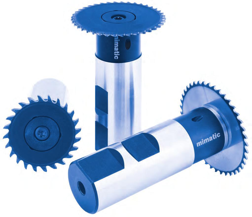
138 Sawing, Cutting, Slitting
139 Milling Thread Milling Extended program Face Finish Milling Notch Impact Test Gear Milling Extended program Slot Milling Contour and Radius Milling Chamfering, eburring Extended program Sawing, Slitting Sawing, Cutting, Slitting Extended program Bore Machining Reaming Axial Grooving Axial Grooving, adjustable Special Tools Special- and Combination Tools Cutting ata and Technical Information
140 Sawing, Cutting, Slitting Cutting, Sawing, Slitting The expectations of the performance and to the application range of cutting tools continuously evolve. In response to the demand for small yet powerful and specifically process safe operating sawblades, mimatic has developed the tooling system PolySAW. n Larger range of applications n efined tooth and cutting edge geometry n mimatic core competence: Polygon interface g Quadrogon interface n High performance coatings n Internal coolant direct to the edges n Clamping with only one center screw n Special chip space geometry These technical parameters resulted in the mimatic development result PolySAW with a up to tenfold cutting performance in comparsion to conventional solid carbide circular saws. 138

141 Sawing, Cutting, Slitting Sawing Tools in New imensions of Performance n With PolySAW profiles can be machined up to the shoulder n On request: Increased sawing depths (S) achievable with reductions in speed/feed + Re-sharpen-Service 2x + Minimum distance for operations to shoulders: 0,001 The mimatic Polygon Interface A Success Story with Continuous Evolution: Quadrogon 7 mimatic Polygon Interface mimatic Quadrogon* Interface Since their development and launch in 1994, the mimatic polygon interface is the guarantee for high cutting performance with maximum precision and repeatability in the circular milling. In the tool systems PolyMILL and Poly- REAM, the polygon interface enables the reliable circular thread milling and reaming as well as T-slot milling and grooving. In many practical applications, the interface has established itself as a key factor for successful milling operations under difficult conditions. With the development of the new tool systems eepmill and PolySAW, the development of the polygon interface has evolved as well. Under the brand name mimatic Quadrogon, the interface has been optimized specifically for the needs of this new mimatic highperformance tool. * patent-protected. 139
142 Sawing, Cutting, Slitting Basic Holders Cutting data see page 174 Ø 32 Size IN 1835 Form B IN 1835 Form A Complete holder Spare Parts ** dh6 L L1 d1 Size Typ IN Bestell-Nr. Screwdriver * Size Ø B , SW A , SW B , SW A , SW 4 Milling iscs Screw torques max. Type 09 = max. 3,8 Nm Type 11 = max. 10,5 Nm Size Size Type A S max. LP1 of teeth eliverable Ø ,0 6, ,0 7, ,5 6, ,5 7, on request on stock on request on stock Especially for aluminium processing: Ø ,0 7, ,5 7, on stock on stock * Screwdriver and clamping screw included in delivery ** More spare parts see page
143 Sawing, Cutting, Slitting Basic Holders Cutting data see page 174 Ø 40 Size IN 1835 Form B IN 1835 Form A Complete holder Spare Parts ** dh6 L L1 d1 Size Typ IN Bestell-Nr. Screwdriver * Size Ø B , SW A , SW B , SW A , SW 3 Milling iscs Screw torques max. Type 11 = max. 10 5Nm Type 13 = max. 24,5 Nm Size 7 Size Type A S max. LP1 of teeth eliverable Ø ,0 9, ,0 10, ,5 9, ,5 10, on request on stock on request on stock Especially for aluminium processing: Ø ,0 10, ,5 10, on stock on stock * Screwdriver and clamping screw included in delivery ** More spare parts see page
144 Sawing, Cutting, Slitting Basic Holders Cutting data see page 174 Ø 50 Size IN 1835 Form B IN 1835 Form A Complete holder Spare Parts ** dh6 L L1 d1 Size Typ IN Bestell-Nr. Screwdriver * Size Ø B SW A SW B , SW A , SW 4 Milling iscs Screw torques max. Type 13 = max. 24,5 Nm Type 16 = max. 6 Nm Size Size Type A S max. LP1 of teeth eliverable Ø ,0 12, ,0 14, ,5 12, ,5 14, on request on stock on request on stock Especially for aluminium processing: Ø ,0 14, ,5 14, on stock on stock * Screwdriver and clamping screw included in delivery ** More spare parts see page
145 Sawing, Cutting, Slitting Basic Holders Cutting data see page 174 Ø 63 Size IN 1835 Form B IN 1835 Form A Complete holder Spare Parts ** dh6 L L1 d1 Size Typ IN Bestell-Nr. Screwdriver * Size Ø B SW A SW B SW A SW 3 Milling iscs Screw torques max. Type 16 = max. 6 Nm Type 19 = max. 10,5 Nm Size 7 Size Type A S max. LP1 of teeth eliverable Ø ,0 16, ,0 18, ,5 16, ,5 18, on request on stock on request on stock Especially for aluminium processing: Ø ,0 18, ,5 18, on stock on stock * Screwdriver and clamping screw included in delivery ** More spare parts see page

146 Sawing, Cutting, Slitting Basic Holders Cutting data see page 174 Ø 80 Size IN 1835 Form B IN 1835 Form A Complete holder Spare Parts ** dh6 L L1 d1 Size Typ IN Bestell-Nr. Screwdriver * Size Ø B SW A SW B , SW A , SW 4 Milling iscs Screw torques max. Type 19 = max. 10,5 Nm Type 25 = max. 24,5 Nm Size Size Type A S max. LP1 of teeth eliverable Ø ,0 20, ,0 25, ,5 20, ,5 25, on request on stock on request on stock Especially for aluminium processing: Ø ,0 25, ,5 25, on stock on stock * Screwdriver and clamping screw included in delivery ** More spare parts see page


147 Sawing, Cutting, Slitting Basic Holders Cutting data see page 174 Ø Size IN 1835 Form B IN 1835 Form A Complete holder Spare Parts ** dh6 L L1 d1 Size Typ IN Bestell-Nr. Screwdriver * Size Ø B , SW A , SW 4 Milling iscs Screw torques max. Type 25 = max. 24,5 Nm Size 7 Size Type A S max. LP1 of teeth eliverable Ø Ø on stock on stock * Screwdriver and clamping screw included in delivery ** More spare parts see page

148 Sawing, Cutting, Slitting Basic Holders with Location Bore Cutting data see page 174 Assembly instruction see page 182 Size Complete holder Accessories Spare Parts ** Type dh6 B MN L L1 d1 d2 Bestell-Nr. Key Screwdriver * Size ,4 36, SW ,4 36, SW ,4 36, SW ,4 50, , SW 4 Basic Holders with Screw-in Thread Screw torques max. Type 16 = max. 6 Nm Type 19 = max. 10,5 Nm Type 25 = max. 24,5 Nm Cutting data see page 174 Size Please adapt cutting data to overhangs length Spare part No. Type Form d1 d2 L L1 M d g6 L PF Screwdriver * Size A ,5 20 M , SW B 30-36,5 - M , SW3 Screw torque max. 3,8 Nm Recoended tightening torque for screw-in circular milling body End-wrench see page 157 Thread size (M) Wrench size Tightening torque Nm * Screwdriver and clamping screw included in delivery ** More spare parts see page M5 7 8 M M M M M
149 Sawing, Cutting, Slitting Saw Blade Arbors for mimatic Saw Blade Holders Cutting data see page 174 Size istance sleeve When using PolySaw ECO, as well as eepmill ECO, the cutting depth is reduced by 6 or 7 Complete holder Spare Parts ** dh6 L L1 1 System Typ Bestell-Nr. Screwdriver * Size ECO SW SW 4 Screw torques max. Type 35 = max. 24,5 Nm Type 25 = max. 24,5 Nm Assembly and Spare Parts 7 Spare Parts Type Screw Clamping disc Assembly notes Please tighten the clamping screw with the specified torque. In the selection of the eepmill basic holder and machine tool holder should be chosen the shortest possible setup. Service Please don't hesitate to take the advantage of the mimatic service. Mimatic engineers will offer machining recoendations to optimize your specific applications Screw torques max Type 09 M4 3,8 Nm Type 11 M6 10,5 Nm Type 13 M8 24,5 Nm Type 16 M5 6,0 Nm Type 19 M6 10,5 Nm Type 24 M8 24,5 Nm Type 35 M8 24,5 Nm 147


150 Turn Cut Milling Turn Cut Milling with Turn Cut Milling instead of parting off: Faster parting off than anybody else! The new process technology from mimatic is called Turn Cut Milling with PolySAW: Turn Cut Milling instead of parting off! This is the combined know how of live tools and cutting tools by mimatic. PolySAW turn cut milling is enabled by the new QUAROGON interface developed by mimatic. Quadrogon safely and reliable transmits the high performance during Turn Cut Milling. Short process times Process reliability Material saving Surface quality Absence of burrs Short chips The high number of cutting-teeth of the PolySAW milling cutter also has a positive effect when machining asyetric or thin components. ue to its continuous and uninterrupted tooth engagement and the resulting smooth machining process. PolySAW milling cutters may look like conventional saws on first sight, however, mimatic has provided PolySAW with all the properties of high-value milling tools. The process reliability and performance of PolySAW is unmatched by conventional saws. Examples for high quality TurnCut Milling Material: steel Rz=1,0-2,7 Ra=0,17-0,53 fz =0,015-0,03 Vc= m/min Material: aluminium Rz =1,7-2,8 Ra =0,36-0,6 fz =0,02-0,03 Vc = m/min Material: aluminium Rz =1,7-4,0 Ra =0,39-0,85 fz =0,02-0,03 Vc = m/min Material: aluminium Rz =1,6-3,2 Ra =0,38-0,62 fz =0,02-0,03 Vc = m/min 148


151 Turn Cut Milling Turn Cut Milling with Turn Cut Milling instead of parting off: Faster parting off than anybody else! Cutting of VA structured components Vc = 160 m/min Fz = 0,1 Turn Cut Milling : steel 16MnCrS5 Vc = 160 m/min Fz = 0,05 bei 40 Zähnen Turn Cut Milling: aluminium Vc = 800 m/min feed = 7m / min 7 Turn Cut Milling: copper ETP Vc = 300 m/min Fz = 0,08 videos to be found on youtube: 149

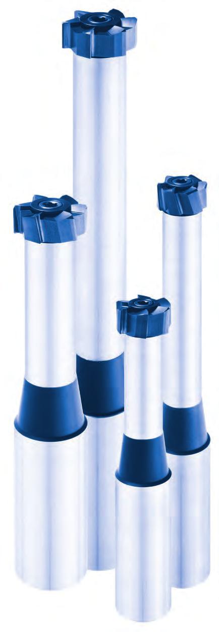

152 Reaming
153 Milling Thread Milling Extended program Face Finish Milling Notch Impact Test Gear Milling Extended program Slot Milling Contour and Radius Milling Chamfering, eburring Extended program Sawing, Slitting Sawing, Cutting, Slitting Extended program Bore Machining Reaming Axial Grooving Axial Grooving, adjustable Special Tools Special- and Combination Tools Cutting ata and Technical Information


154 Reaming RPK-Reamers with Polygonal Insert Seat for High Chip Removal A new generation of Reamers to machine blind and through holes in components with greater accuracy. The polygonal connection between the insert and the shank provides improved strength allowing greater cutting forces which in turn makes for economical machining. Two basic types RPK 40 and RPK 42 are available, which cover a wide range of applications by their different shanks and cutting insert designs. Changing the insert is quick and easy. The front clamping screw absorbs none of the cutting forces and is merely there to hold the insert in place. ifferent overall lengths are available. Advantages High-tensile connection by polygonal insert seat Easy insert change Internal coolant supply directly to the cutting edge High concentricity Longer durabilities High precision Higher volume of metal removed by reaming Higher feeds Shorter processing times Special dimensions available Configurations Shank sizes 16 / 20 Lengths design short / long Left-hand twist for through holes Straight grooves for blind bores iameter sizes: 12,00-20,20 Any gate geometries Any tolerances Cutting materials: carbide Coatings: 152

.")


 1 = (Thin layer) Example: R P K 4 0 M 2 0, 1 0 0 +10-12 L B G 1 1 Solid")
155 Reaming Order-Key for Your Individual Customizing of Reamers Order numbers for reamers are predefined for coon applications within the order tables. Alternatively, the user can completely individually customize its own ream (intermediate dimension, geometry, cutting material, tolerance,...). An additional key is generated with the following table that serves your initial order. For subsequent orders, you will receive a short order number assigned. Type Size iameter Tolerance Gate geometry Cutting mat. Coating RPK 40 = Straight grooves for blind bores RPK 42 = Left-hand twist for through holes J = 16 M = 20 Specifying in H7 see page 156 and in the table below 1 = 0 = without (blank) 1 = (Thin layer) Example: R P K 4 0 M 2 0, L B G 1 1 Solid carbide reamer head Internal coolant Reamer holder Central clamping screw Bouncing disc to the coolant redirection 8 153
156 Reaming Reamer Holders with Polygonal Interface Gate Geometries Page 156 Cutting data see page 172 Typ RPS 400 IN 1835 Form A Spare part No. Shank size min.-max. rilling depth d h6 d1 E L L1 escription Shank mat. T15 / T20 IP Screwdriver * Screw * Bouncing disc J ,00-16,20 3 x RPS400J J ,00-16,20 5 x RPS400J M ,21-20,20 3 x RPS400M M ,21-20,20 5 x RPS400M * Screwdriver and clamping screw included in delivery Screw torques max T15 IP 3,8 Nm T20 IP 5,5 Nm Reamer Heads with Polygonal Interface Chip grooves with left-hand twist for through holes For steel materials (P, M) Cutting data see page 172 Please generate order-key for individual customizing and intermediate sizes (see page 153) Shank size Type Tolerance L P of edges Gate geometry escription J RPK 42 12,00 H7 9,4 6 LBG RPK42J12,00H7LBG J RPK 42 13,00 H7 9,4 6 LBG RPK42J13,00H7LBG J RPK 42 14,00 H7 9,4 6 LBG RPK42J14,00H7LBG J RPK 42 15,00 H7 9,4 6 LBG RPK42J15,00H7LBG J RPK 42 16,00 H7 9,4 6 LBG RPK42J16,00H7LBG M RPK 42 17,00 H7 9,4 6 LBG RPK42M17,00H7LBG M RPK 42 18,00 H7 9,4 6 LBG RPK42M18,00H7LBG M RPK 42 19,00 H7 9,4 6 LBG RPK42M19,00H7LBG M RPK 42 20,00 H7 9,4 6 LBG RPK42M20,00H7LBG
157 Reaming Reamer Heads with Polygonal Interface Straight chip grooves for blind bores For steel materials (P, M) Cutting data see page 172 Please generate order-key for individual customizing and intermediate sizes (see page 153) Shank size Type Tolerance L P of edges Gate geometry escription J RPK 40 12,00 H7 9,4 6 LBG RPK40J12,00H7LBG J RPK 40 13,00 H7 9,4 6 LBG RPK40J13,00H7LBG J RPK 40 14,00 H7 9,4 6 LBG RPK40J14,00H7LBG J RPK 40 15,00 H7 9,4 6 LBG RPK40J15,00H7LBG J RPK 40 16,00 H7 9,4 6 LBG RPK40J16,00H7LBG M RPK 40 17,00 H7 9,4 6 LBG RPK40M17,00H7LBG M RPK 40 18,00 H7 9,4 6 LBG RPK40M18,00H7LBG M RPK 40 19,00 H7 9,4 6 LBG RPK40M19,00H7LBG M RPK 40 20,00 H7 9,4 6 LBG RPK40M20,00H7LBG Straight chip grooves for blind bores For cast iron materials (K) Cutting data see page 172 Please generate order-key for individual customizing and intermediate sizes (see page 153) Shank size Type Tolerance L P of edges Gate geometry escription J RPK 40 12,00 H7 9,4 6 CN RPK40J12,00H7CN J RPK 40 13,00 H7 9,4 6 CN RPK40J13,00H7CN J RPK 40 14,00 H7 9,4 6 CN RPK40J14,00H7CN J RPK 40 15,00 H7 9,4 6 CN RPK40J15,00H7CN J RPK 40 16,00 H7 9,4 6 CN RPK40J16,00H7CN M RPK 40 17,00 H7 9,4 6 CN RPK40M17,00H7CN M RPK 40 18,00 H7 9,4 6 CN RPK40M18,00H7CN M RPK 40 19,00 H7 9,4 6 CN RPK40M19,00H7CN M RPK 40 20,00 H7 9,4 6 CN RPK40M20,00H7CN Straight chip grooves for blind bores For aluminium cast alloys (N) Cutting data see page 172 Please generate order-key for individual customizing and intermediate sizes (see page 153) Shank size Type Tolerance L P of edges Gate geometry escription J RPK 40 12,00 H7 9,4 6 CNG RPK40J12,00H7CNG J RPK 40 13,00 H7 9,4 6 CNG RPK40J13,00H7CNG J RPK 40 14,00 H7 9,4 6 CNG RPK40J14,00H7CNG J RPK 40 15,00 H7 9,4 6 CNG RPK40J15,00H7CNG J RPK 40 16,00 H7 9,4 6 CNG RPK40J16,00H7CNG M RPK 40 17,00 H7 9,4 6 CNG RPK40M17,00H7CNG M RPK 40 18,00 H7 9,4 6 CNG RPK40M18,00H7CNG M RPK 40 19,00 H7 9,4 6 CNG RPK40M19,00H7CNG M RPK 40 20,00 H7 9,4 6 CNG RPK40M20,00H7CNG
158 Reaming Gate Geometries Gate geometry Chip breaker Chip angle Gate code Code Code Code YES NO B N 0 LB LN L YES NO B N 6 G LBG LNG YES NO B N 12 R LBR LNR YES NO B N 0 EB EN E YES NO B N 6 G EBG ENG YES NO B N 12 R EBR ENR YES NO B N 0 GB GN G YES NO B N 6 G GBG GNG YES NO B N 12 R GBR GNR YES NO B N 0 CB CN C YES NO B N 6 G CBG CNG YES NO B N 12 R CBR CNR YES NO B N 0 AB AN A YES NO B N 6 G ABG ANG YES NO B N 12 R ABR ANR YES NO B N 0 B N YES NO B N 6 G BG NG YES NO B N 12 R BR NR YES NO B N 0 RB RN R YES NO B N 6 G RBG RNG YES NO B N 12 R RBR RNR W YES NO YES NO YES NO B N B N B N 0 6 G 12 R WB WN WBG WNG WBR WNR SPECIAL S
159 Reaming Ream Addition Ream diameter () Ream addition ( to the dia.) 16,00 0,10-0,25 > 16,00 0,20-0,30 Information Before reaming radial on round parts the part must be spot-faced 8 Accessories: Screw river and Wrenches Size Torx PLUS driver Size Torx driver Size Allen wrench IN 911 Size Open-end wrench IN 894 T6 IP T SW SW T8 IP T SW 2, SW T15 IP T SW SW T20 IP T SW SW SW SW SW SW SW SW

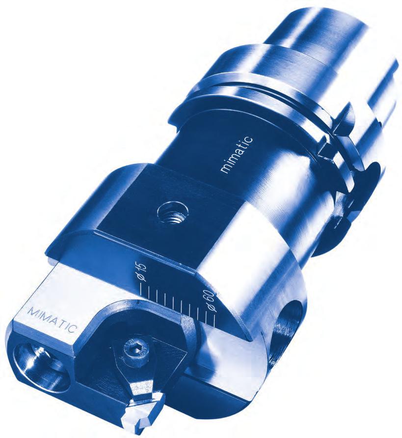

160 Axial Grooving, adjustable
161 Milling Thread Milling Extended program Face Finish Milling Notch Impact Test Gear Milling Extended program Slot Milling Contour and Radius Milling Chamfering, eburring Extended program Sawing, Slitting Sawing, Cutting, Slitting Extended program Bore Machining Reaming Axial Grooving Axial Grooving, adjustable Special Tools Special- and Combination Tools Cutting ata and Technical Information
162 Axial Grooving, adjustable Axial Cutting Tools with scalable cutting diameter and fine-adjustment all Axial-Cutting Tools without Insert Holders ISO ISO (MAS-BT) Adjustment Range Adjustment Range Adjustment Range Ø Shank size L F L GK d 2 B W B H SK SK BT IN Adjustment Range Adjustment Range Adjustment Range Ø Shank size L F L GK d 2 B W B H HSK Komet ABS Adjustment Range Adjustment Range Adjustment Range Ø Shank size L F L GK d 2 B W B H ABS ABS
163 Axial Grooving, adjustable Axial Cutting Tools with scalable cutting diameter and fine-adjustment all Axial-Cutting Tools without Insert Holders ISO Capto Adjustment Range Adjustment Range Spare part No. Adjustment Range Ø Shank size L F L GK d 2 B W B H7 Fitting screw IN 7379 Size C6 70,6 65, M8 x 20 Insert Holders Special-Insert holders on request Spare part No. Adjustment Range Ø L HA B f6 H S l 1 S max. Clamping claw Screw * Screwdriver * Screw torque 0,9 Nm 9 Spare part No. Adjustment Range Ø L HA B f6 H S l 1 S max. Clamping claw Screw * Screwdriver * * Screwdriver and clamping screw included in delivery Screw torque 0,9 Nm 161
164 Axial Grooving, adjustable Insert Holders Special-Insert holders on request Spare part No. Adjustment Range Ø L HA B f6 H S l 1 S max. Clamping claw Screw * Screwdriver * , Unprofiled Inserts Screw torque 5,5 Nm Cutting data see page 175 without profile Size Width Height S max. K10 P25 FKN A 6R on request on request without profile Size E Height S max. K10 FKN 01AX LI AX LI AX LI 6, * Screwdriver and clamping screw included in delivery Various forms of insert profiles. Other profiles according to IN or drawing are available on request. 162
 up to a Cutting depth of max. 4,0 Cutting width of max.")

165 Axial Grooving, adjustable Function and Handling Technical ata Complete tool, consisting of Axial-Cutting-Tool 2 insert holders for cutting range a) b) Advantages This tool makes operations possible in workpieces, which cannot be clamped on turning machines. Applications Making grooves (IN- or special grooves) up to a Cutting depth of max. 4,0 Cutting width of max. 6,5 Rough Adjustment 1. Removing the clamping screw 2. Rough adjustment of the insertholder over the screening system (2,5 ) 3. Low tighten the clamping screw Fine Adjustment 1. Fine adjustment over the fine adjustment screw 2. Tighten the clamping screw Request Form for Grooving Please download our fillable PF form for a detailed grooving request and fax or send us back via mimatic.de 9 Request form: 163


166 Special- and Combination Tools
167 Milling Thread Milling Extended program Face Finish Milling Notch Impact Test Gear Milling Extended program Slot Milling Contour and Radius Milling Chamfering, eburring Extended program Sawing, Slitting Sawing, Cutting, Slitting Extended program Bore Machining Reaming Axial Grooving Axial Grooving, adjustable Special Tools Special- and Combination Tools Cutting ata and Technical Information


168 Special- and Combination Tools Special Solutions Here you see examples of our products and our expertise in the area of special cutting tools. o you have a special application or a production problem? Ask us we gladly accept the challenge and develop together with you a solution in the areas of: Milling Thread Milling Slots Chamfering Facing Grooving Thread milling Fittings Industry 166


169 Special- and Combination Tools Thread milling Automotive Industry Coon Rail HSK or mi Cutting Tool n jiggering n chamfering Materials: 1. 20MnVS6 2. X15 CrNiSi20 (IN ) HSK or mi Cutting Tool n drilling n face milling n Solid carbide twist drill n chamfering HSK or mi Milling Tool 5 different inserts for n chamfering n thread milling n face milling n counterboring Material: AlMgSi1 (IN ) HSK or mi Milling Tool n contour milling Material: 16MnCrS


170 Special- and Combination Tools Special Solutions Turn-cut milling with TF-AGW and PolySAW Process reliable cutting with short chips and cycle times of almost all materials and geometries. Large thread milling M330x6 with STC1 Material: S355JR Countersinking and circular milling of a brake body with E inserts Material: GGG50 168


171 Special- and Combination Tools Gear milling with STC Material: 58CrV4 Milling of hold grooves in conrods with STC Milling of flanges of motor blocks with TriMILL


172 Cutting ata and Technical Information
173 Milling Thread Milling Extended program Face Finish Milling Notch Impact Test Gear Milling Extended program Slot Milling Contour and Radius Milling Chamfering, eburring Extended program Sawing, Slitting Sawing, Cutting, Slitting Extended program Bore Machining Reaming Axial Grooving Axial Grooving, adjustable Special Tools Special- and Combination Tools Cutting ata and Technical Information
174 Cutting ata and Technical Information Cutting ata Reference Values PolyREAM SolidCUT Material Strength Measurement Ø 2,4-3,15 Ø 4 Ø 4,8-20 at Ø 0,2 Vc (m/min.) fz Vc (m/min.) fz fz fz A R F N S H 1.1 General construction steel < 800 N/² ,20-0, ,03-0,04 0,03-0,06 0,05-0, Free cutting steel < 800 N/² ,20-0, ,03-0,04 0,03-0,06 0,05-0, Unalloyed cementation steel < 800 N/² ,20-0, ,03-0,04 0,03-0,06 0,05-0, Alloyed cementation steels < 1000 N/² ,15-0, ,01-0,02 0,01-0,03 0,05-0, Unalloyed heat-treatable steel < 850 N/² ,20-0, ,01-0,02 0,01-0,03 0,05-0, Unalloyed heat-treatable steel < 1000 N/² ,15-0, ,01-0,02 0,01-0,03 0,05-0, Alloyed heat-treatable steel < 800 N/² ,20-0, ,03-0,04 0,03-0,06 0,05-0, Alloyed heat-treatable steel < 1300 N/² ,12-0, ,01-0,02 0,03-0,05 0,04-0, Cast < 850 N/² ,20-0, ,01-0,02 0,04-0,07 0,05-0, Nitriding steel < 1000 N/² ,15-0, ,01-0,02 0,04-0,07 0,05-0, Nitriding steel < 1200 N/² ,15-0, ,01-0,02 0,03-0,05 0,04-0, Ball bearing steel < 1200 N/² ,15-0, ,01-0,02 0,03-0,05 0,04-0, Spring steel < 1200 N/² ,15-0, ,01-0,02 0,03-0,05 0,04-0, Rapid steel < 1300 N/² ,12-0, ,01-0,02 0,03-0,05 0,04-0, Cold work tool steel < 1300 N/² ,12-0, ,01-0,02 0,03-0,05 0,04-0, Hot work tool steel < 1300 N/² ,12-0, ,01-0,02 0,03-0,05 0,04-0, Stainless steel, sulphured < 850 N/² ,20-0, ,03-0,04 0,03-0,04 0,05-0, Stainless steel, ferritic < 750 N/² ,20-0, ,03-0,04 0,03-0,04 0,05-0, Stainless steel, martensitic < 900 N/² ,15-0, ,03-0,04 0,03-0,04 0,05-0, Stainless steel, ferritic/martensitic <1100 N/² ,15-0, ,03-0,04 0,03-0,04 0,05-0, Stainless steel, austenitic/ferritic < 850 N/² ,20-0, ,03-0,04 0,03-0,04 0,05-0, Stainless steel, austenitic < 750 N/² ,20-0, ,03-0,04 0,03-0,04 0,05-0, Heat-resisting steel < 1100 N/² ,15-0, ,03-0,04 0,03-0,04 0,05-0, Flake-graphite cast iron N/² ,20-0, ,03-0,07 0,03-0,07 0,04-0, Flake-graphite cast iron N/² ,20-0, ,03-0,07 0,03-0,07 0,04-0, Spheroidal graphite cast iron N/² ,20-0, ,03-0,07 0,03-0,07 0,04-0, Spheroidal graphite cast iron N/² ,20-0, ,03-0,07 0,03-0,07 0,04-0, Whiteheart malleable cast iron N/² ,20-0, ,03-0,07 0,03-0,07 0,04-0, Whiteheart malleable cast iron N/² ,20-0, ,03-0,07 0,03-0,07 0,04-0, Blackheart malleable cast iron N/² ,20-0, ,03-0,07 0,03-0,07 0,04-0, Blackheart malleable cast iron N/² ,20-0, ,03-0,07 0,03-0,07 0,04-0, Aluminium (unalloyed, low alloyed) < 350 N/² ,20-0, ,05-0,07 0,05-0,07 0,06-0, Aluminium alloys < 0,5% Si < 500 N/² ,20-0, ,05-0,07 0,05-0,07 0,06-0, Aluminium alloys 0,5-10% Si < 400 N/² ,05-0,07 0,05-0,07 0,06-0, Aluminium alloys 10-15% Si < 400 N/² ,05-0,07 0,05-0,07 0,06-0, Aluminium alloys > 15% Si < 400 N/² ,05-0,07 0,05-0,07 0,06-0, Cooper (unalloyed, low alloyed) < 350 N/² ,20-0, ,05-0,07 0,05-0,07 0,06-0, Copper wrought alloys < 700 N/² 4.8 Cooper special alloys < 200 HB 4.9 Cooper special alloys < 300 HB 4.10 Cooper special alloys > 300 HB 4.11 Brass, short-chipping, Bronze, Red brass < 600 N/² ,20,0, ,05-0,07 0,05-0,07 0,06-0, Brass, long-chipping < 600 N/² 4.13 Thermoplastic ,08-0,1 0,08-0,1 0,1-0, Thermosetting plastic ,08-0,1 0,08-0,1 0,1-0, Fibre-reinforced plastics ,02-0,04 0,02-0,04 0,03-0, Magnesium and magnesium alloys < 850 N/² 4.17 Graphite 4.18 Wolfram and wolfram alloys 4.19 Molybdenum and molybdenum alloys Pure nickel Nickel alloys ,20-0, Nickel alloys < 850 N/² ,20-0, ,02-0,04 0,02-0,04 0,03-0, Nickel-chrome alloys Nickel- and cobalt alloys < 1300 N/² 5.6 Nickel- and cobalt alloys < 1300 N/² 5.7 High temperature alloys < 1300 N/² 5.8 Nickel-cobalt-(chrome-) alloys < 1400 N/² 5.9 Pure Titanium < 900 N/² 5.10 Titanium alloys < 700 N/² ,15-0, Titanium alloys < 1200 N/² ,12-0, ,01-0,03 0,01-0,03 0,01-0, Hardened steel < 45 HRc ,04-0, ,03-0,05 0,03-0, HRc ,04-0, ,03-0,05 0,03-0, HRc ,03-0, ,02-0,04 0,02-0, HRc ,03-0, HRc ,02-0,04 * The indicated feed values apply only with circular bringing in loop. uring linear bringing in movement the feed motion amounts to max. 30% 172
175 Cutting ata and Technical Information System 14, TrioCUT PolyMILL 3/6 Cutting Edges TriMILL 12, 14,5, 15, 17, 20, 25 21, 26 Vc (m/min.) fz fz Vc (m/min.) fz Vc (m/min.) fz ,1-0,3 0,05-0, ,05-0, ,05-0, ,1-0,3 0,05-0, ,05-0, ,05-0, ,1-0,3 0,05-0, ,05-0, ,05-0, ,1-0,3 0,05-0, ,05-0, ,05-0, ,1-0,3 0,05-0, ,05-0, ,05-0, ,1-0,3 0,05-0, ,05-0, ,05-0, ,1-0,3 0,05-0, ,05-0, ,05-0, ,1-0,2 0,05-0, ,05-0, ,05-0, ,1-0,3 0,05-0, ,05-0, ,1-0,2 0,05-0, ,05-0, ,05-0, ,1-0,2 0,05-0, ,05-0, ,05-0, ,1-0,2 0,05-0, ,05-0, ,1-0,2 0,05-0, ,05-0, ,05-0, ,1-0,2 0,05-0, ,05-0, ,05-0, ,1-0,2 0,05-0, ,05-0, ,05-0, ,1-0,2 0,05-0, ,05-0, ,05-0, ,05-0, ,05-0, ,1-0,3 0,05-0, ,05-0, ,05-0, ,05-0, ,05-0, ,05-0, ,05-0, ,1-0,2 0,05-0, ,05-0, ,05-0, ,05-0, ,1-0,3 0,05-0, ,05-0, ,05-0, ,1-0,3 0,05-0, ,05-0, ,05-0, ,1-0,3 0,05-0, ,05-0, ,05-0, ,1-0,3 0,05-0, ,05-0, ,05-0, ,1-0,3 0,05-0, ,05-0, ,05-0, ,1-0,3 0,05-0, ,05-0, ,05-0, ,1-0,3 0,05-0, ,05-0, ,05-0, ,1-0,3 0,05-0, ,05-0, ,05-0, ,1-0,3 0,05-0, ,05-0,12 0,05-0, ,1-0,3 0,05-0, ,05-0,12 0,05-0, ,15-0, ,05-0, ,15-0, ,05-0, ,15-0, ,05-0, ,15-0, ,05-0, ,15-0, ,05-0, ,05-0, ,05-0, ,05-0, ,05-0, ,01-0, ,01-0, ,01-0, ,01-0, ,03-0, ,03-0, ,03-0,
176 Cutting ata and Technical Information Cutting ata Reference Values STC PolySAW / eepmill Material Strength STC-1 STC-2 STC-3 0,3 x S max. 0,6 x S max. S max. Vc (m/min.) fz fz Vc (m/min.) fz fz fz A R F N S H 1.1 General construction steel < 800 N/² ,05-0,2 0,05-0, ,03-0,05 0,02-0,04 0,015-0, Free cutting steel < 800 N/² ,05-0,2 0,05-0, ,03-0,05 0,02-0,04 0,015-0, Unalloyed cementation steel < 800 N/² ,05-0,2 0,05-0, ,03-0,05 0,02-0,04 0,015-0, Alloyed cementation steels < 1000 N/² ,05-0,2 0,05-0, ,03-0,05 0,02-0,04 0,015-0, Unalloyed heat-treatable steel < 850 N/² ,05-0,2 0,05-0, ,03-0,05 0,02-0,04 0,015-0, Unalloyed heat-treatable steel < 1000 N/² ,05-0,2 0,05-0, ,03-0,05 0,02-0,04 0,015-0, Alloyed heat-treatable steel < 800 N/² ,05-0,2 0,05-0, ,03-0,05 0,02-0,04 0,015-0, Alloyed heat-treatable steel < 1300 N/² ,05-0,2 0,05-0, ,03-0,05 0,02-0,04 0,015-0, Cast < 850 N/² ,05-0,2 0,05-0, ,03-0,05 0,02-0,04 0,015-0, Nitriding steel < 1000 N/² ,05-0,2 0,05-0, ,03-0,05 0,02-0,04 0,015-0, Nitriding steel < 1200 N/² ,05-0,2 0,05-0, ,03-0,05 0,02-0,04 0,015-0, Ball bearing steel < 1200 N/² ,05-0,2 0,05-0, ,03-0,05 0,02-0,04 0,015-0, Spring steel < 1200 N/² ,05-0,2 0,05-0, ,03-0,05 0,02-0,04 0,015-0, Rapid steel < 1300 N/² ,05-0,2 0,05-0, ,03-0,05 0,02-0,04 0,015-0, Cold work tool steel < 1300 N/² ,05-0,2 0,05-0, ,03-0,05 0,02-0,04 0,015-0, Hot work tool steel < 1300 N/² ,05-0,2 0,05-0, ,03-0,05 0,02-0,04 0,015-0, Stainless steel, sulphured < 850 N/² ,05-0,2 0,05-0, ,03-0,05 0,02-0,04 0,015-0, Stainless steel, ferritic < 750 N/² ,05-0,2 0,05-0, ,03-0,05 0,02-0,04 0,015-0, Stainless steel, martensitic < 900 N/² ,05-0,2 0,05-0, ,03-0,05 0,02-0,04 0,015-0, Stainless steel, ferritic/martensitic <1100 N/² ,05-0,2 0,05-0, ,03-0,05 0,02-0,04 0,015-0, Stainless steel, austenitic/ferritic < 850 N/² ,05-0,2 0,05-0, ,03-0,05 0,02-0,04 0,015-0, Stainless steel, austenitic < 750 N/² ,05-0,2 0,05-0, ,03-0,05 0,02-0,04 0,015-0, Heat-resisting steel < 1100 N/² ,05-0,2 0,05-0, ,03-0,05 0,02-0,04 0,015-0, Flake-graphite cast iron N/² ,05-0,2 0,05-0, ,03-0,05 0,02-0,04 0,015-0, Flake-graphite cast iron N/² ,05-0,2 0,05-0, ,03-0,05 0,02-0,04 0,015-0, Spheroidal graphite cast iron N/² ,05-0,2 0,05-0, ,03-0,05 0,02-0,04 0,015-0, Spheroidal graphite cast iron N/² ,05-0,2 0,05-0, ,03-0,05 0,02-0,04 0,015-0, Whiteheart malleable cast iron N/² ,05-0,2 0,05-0, ,03-0,05 0,02-0,04 0,015-0, Whiteheart malleable cast iron N/² ,05-0,5 0,05-0, ,03-0,05 0,02-0,04 0,015-0, Blackheart malleable cast iron N/² ,05-0,2 0,05-0, ,03-0,05 0,02-0,04 0,015-0, Blackheart malleable cast iron N/² ,05-0,2 0,05-0, ,03-0,05 0,02-0,04 0,015-0, Aluminium (unalloyed, low alloyed) < 350 N/² ,05-0,2 0,05-0, ,03-0,05 0,02-0,04 0,015-0, Aluminium alloys < 0,5% Si < 500 N/² ,05-0,2 0,05-0, ,03-0,05 0,02-0,04 0,015-0, Aluminium alloys 0,5-10% Si < 400 N/² 4.4 Aluminium alloys 10-15% Si < 400 N/² 4.5 Aluminium alloys > 15% Si < 400 N/² 4.6 Cooper (unalloyed, low alloyed) < 350 N/² ,1-0,25 0,1-0, ,03-0,05 0,02-0,04 0,015-0, Copper wrought alloys < 700 N/² 4.8 Cooper special alloys < 200 HB 4.9 Cooper special alloys < 300 HB 4.10 Cooper special alloys > 300 HB 4.11 Brass, short-chipping, Bronze, Red brass < 600 N/² ,1-0,25 0,1-0, ,03-0,05 0,02-0,04 0,015-0, Brass, long-chipping < 600 N/² 4.13 Thermoplastic ,1-0,25 0,1-0, ,03-0,05 0,02-0,04 0,015-0, Thermosetting plastic ,1-0,25 0,1-0, ,03-0,05 0,02-0,04 0,015-0, Fibre-reinforced plastics 4.16 Magnesium and magnesium alloys < 850 N/² 4.17 Graphite ,1-0,25 0,1-0, ,03-0,05 0,02-0,04 0,015-0, Wolfram and wolfram alloys 4.19 Molybdenum and molybdenum alloys Pure nickel Nickel alloys ,05-0,2 0,05-0, ,03-0,05 0,02-0,04 0,015-0, Nickel alloys < 850 N/² ,05-0,2 0,05-0, ,03-0,05 0,02-0,04 0,015-0, Nickel-chrome alloys Nickel- and cobalt alloys < 1300 N/² 5.6 Nickel- and cobalt alloys < 1300 N/² 5.7 High temperature alloys < 1300 N/² 5.8 Nickel-cobalt-(chrome-) alloys < 1400 N/² 5.9 Pure Titanium < 900 N/² 5.10 Titanium alloys < 700 N/² ,01-0,08 0,01-0, ,03-0,05 0,02-0,04 0,015-0, Titanium alloys < 1200 N/² ,01-0,08 0,01-0, ,03-0,05 0,02-0,04 0,015-0, Hardened steel < 45 HRc ,03-0,1 0,03-0, ,03-0,05 0,02-0,04 0,015-0, HRc ,03-0,1 0,03-0, ,03-0,05 0,02-0,04 0,015-0, HRc ,01-0,05 0,01-0, ,03-0,05 0,02-0,04 0,015-0, HRc ,01-0,04 0,01-0, ,03-0,05 0,02-0,04 0,015-0, HRc * The indicated feed values apply only with circular bringing in loop. uring linear bringing in movement the feed motion amounts to max. 30% 174
177 Cutting ata and Technical Information Axial Cutting CT-Counterboring TrioCUT rill Milling FKN 7x 6x 3x 3x shaft shaft shaft shaft Vc (m/min.) Vc (m/min.) fz Vc (m/min.) Vc (m/min.) Vc (m/min.) Vc (m/min.) fz Vc (m/min.) fz ,05-0, , ,2-0, ,05-0, , ,2-0, ,05-0, , ,2-0, ,05-0, , ,2-0, ,05-0, , ,2-0, ,05-0, , ,2-0, ,05-0, , ,2-0, ,05-0, , ,15-0, ,05-0, , ,2-0, ,05-0, , ,15-0, ,05-0, , ,15-0, ,05-0, , ,15-0, ,05-0, , ,15-0, ,05-0, , ,15-0, ,05-0, , ,15-0, ,05-0, , ,15-0, ,05-0, , ,05-0, , ,05-0, , ,2-0, ,05-0, , ,05-0, , ,05-0, , ,15-0, ,05-0, , ,05-0, , ,2-0, ,05-0, , ,2-0, ,05-0, , ,2-0, ,05-0, , ,2-0, ,05-0, , ,2-0, ,05-0, , ,2-0, ,05-0, , ,2-0, ,05-0, , ,2-0, ,05-0, , ,2-0, ,05-0, , ,2-0, , ,05-0, , ,05-0, , ,05-0, , ,05-0, , , ,
178 Cutting ata and Technical Information Material Examples Material subgroup Identifier Norm marking IN- Tensile strength N/ 2 Hardness HB AISI / SAE / ASTM Unalloyed steel 800 N/ 2 Constructional steel St A 264 St St A 572 Carbon steel C M 1010 C C C Machining steel 35S S SMn SMn SMnPb L13 9SMnPb L14 Case hardened steel Quenched steel 13Cr MnCr C Unalloyed steel 1000 N/ 2 Constructional steel Cf Ck Ck Ck Cr CrMo CrMo CrMo Cr CrMo CrNiMo Mn Cr CrMo CrMo CrMo C35 E C C C Cf Ck Ck Case hardened steel 14NiCr MnCr Ck Unalloyed and alloyed steel 1200 N/ 2 Case hardened steel 14NiCr MnCr 5 V CrNiMo Nitriding steel 31CrMio V CrNiMo CMoV
179 Cutting ata and Technical Information Material Examples Material subgroup Identifier Norm marking IN- Tensile strength N/ 2 Hardness HB AISI / SAE / ASTM Unalloyed and Quenched steel 100Cr alloyed steel 25CrMo N/ 2 30CrNiMo CrMo Cr Mn CrMo CrMo Cold work tool steel 100Cr L3 100MnCrW V W CrV L2 50CrV CrV WCrV S1 90MnCrV S X100 CrMoV A2 X165 CrMoV X210 Cr X210 CrW X50 CrMoW Hot work tool steel 35NiCrMo CrMnMo WCrV S1 55NiCrMoV L6 60NiCrMoV X30WCrV WCrV H21 X32 CrMoV H10 X36CrMo X38CrMoV H11 X40CrMoV H13 X42Cr Unalloyed and Heat resistant steel 35CrNiMo alloyed steel NiCr19 CoMo N/ 2 X5NiCrTi Tool steel 50CrV NiCrMoV X155CrVMo X210CrW Stainless steel standard alloyed GX10CrNi (V2A) GX20Cr GX5CrNI CF-8 GX8CrNi X10Cr X10CrNiS X105CrMo C X12CrMoS F X12CrNi X12CrS
180 Cutting ata and Technical Information Material Examples Material subgroup Identifier Norm marking IN- Tensile strength N/ 2 Hardness HB AISI / SAE / ASTM Stainless steel (V2A) standard alloyed X15Cr X2CrNi L X20Cr X17CrNi X22CrNi X3CrNiN X30Cr F X39Cr X46Cr X5CrNi CA6-NM X5CrNi X5CrNi X6CrAl X6CrMo X6 Cr X6Cr Stainless steel with high chrome-nickel rate (V4A) high alloyed GX5CrNiMo CF-8M GX5CrNiNb X1NiCrMoCuN UNSN08904 X6CrNiTi X2CrMoTi X2CrNiMo L X2CrNiMo L X2CrNiMoN LN X2CrNiMo X2CrNiMoN S31803 X4CrNiMoN X7CrNiAl X5CrNiMo X5CrNiMo X5CrNiNb X6CrNb X6CrNiMoTi Ti X6CrNiNb X6CrTi X6CrTi High-speed steel S T15 S T1 S T5 S T4 S M42 S M1 S M7 S M34 S M3 Class2 S M2 S S M41 SC M3 178
181 Cutting ata and Technical Information Material Examples Cast Iron, Nonferrous Metals Material subgroup Identifier Norm marking IN- Tensile strength N/ 2 Hardness HB AISI / SAE / ASTM Cast iron Grey cast iron GG A48-20 B GG A48-25 B GG A48-30 B GG A48-35 B GG A48-45 B GG A48-50 B GG A48-55 B Spherulitic graphite iron GGG GGG GGG GGG Malleable cast iron GTW Material subgroup Identifier Norm marking IN- Tensile strength N/ 2 Hardness HB AISI / SAE / ASTM Aluminium, Cooper, Cooper alloys Aluminium, unalloyed Al Al E-Al A Cooper, unalloyed SF-Cu C Messing, long-chipping CuZn C Bronze, low density G-CuSn 6 ZnNi C Red bronze G-CuSn 5 ZnPb C Aluminium, alloyed Bronze hard G-AlSi A413 G-AlSi 10 MgCu G-AlSi 12 Cu G-AlSi 5 Mg G-AlSi 6 Cu G-AlSi 7 Mg A356.2 G-AlSi 8 Cu G-AlSi 9 Mg G-CuAl 11 Ni CuSn & Zn Aluminium special alloys Aluminium special alloys AlCuMg A AlMg A AlMg B AlMg 1 SiCu AlMg AlMg AlMg A
182 Cutting ata and Technical Information Material Examples Nonferrous Metals Material subgroup Identifier Norm marking IN- Tensile strength N/ 2 Hardness HB AISI / SAE / ASTM Aluminium special alloys Aluminium special alloys AlMgSi AlMgSi AlMn 1 Mg AlMnCu AlZnMgCu AlZnMgCu G-AlMg G-AlMg 5Si Cooper alloys Messing, short-chipping CuZn39Pb CuZN40Mn1Pb CuZn44Pb Nickel alloys Nickel alloys Hastelloy C Hastelloy C Inconel Nimonec Titan alloys Titan alloys TiAl 5 Sn TiAl 6V Cu-Al-Fe alloys Chilled cast iron Ampco 21 Ampco 22 Ampco 25 Ampco 26 Thermoplastic Thermoplastic Polyamid Polystyrol Polyvenylchlorid Ultramid Thermosetting plastic and fibre-reinforced plastic Thermosetting plastic Fibre-reinforced plastic Bakelid Ferrozell Pertinax CFK GFK 180

 Plunge in feed Plunge in the arc Calculation of the middle chip")
 Shaft or bore diameter v f (/min) Plunge feed v f2 (/min)")
 Feed per insert z of inserts a r () Chip depth, radial h m ()")
183 Cutting ata and Technical Information Calculation Formula for the Circular Milling Calculating the feed rate of the cutting center path (Outer contour) Calculating the feed rate of the cutting center path (Inner contour) Plunge in feed Plunge in the arc Calculation of the middle chip thickness n (rpm) Spindle speed vc (m/min) Cutting speed d () Cutter diameter () Shaft or bore diameter v f (/min) Plunge feed v f2 (/min) Effective feed speed v f3 (/min) Prograed feed speed (Cutter center track) f z () Feed per insert z of inserts a r () Chip depth, radial h m () Middle chip thickness


184 Cutting ata and Technical Information Information about Circular Milling Internal milling External milling The best relation between bore diameter and cutter diameter is 2:1 due to smaller angle of contact, which results in a smooth machining. Synchronous milling is recoended. Plunge in with a circle Straight plunge in If possible, always plunge in with a circle. If plunging in straight, only use 1/3 of the feed. After having reached the plunge depth, move with full speed. Prograed feed regarding to cutter center Effective feed regarding to cutter O.. U program U effective Always check the real feed speed at cutter O.. Assembling Instructions Changing Inserts Clamp cutter before changing insert. Loosen insert screw. Remove used insert and clean the insert pocket before clamping new insert. Please use the appropriate TIP hex key for the tighening of the inserts. Changing Clamping Screws Only for circular milling cutter no
185 Cutting ata and Technical Information Information about Circular Thread Milling Internal Thread Right-hand Thread (climb milling) Left-hand Thread (up-cut milling) Left-hand Thread (climb milling) Right-hand Thread (up-cut milling) External Thread Right-hand Thread (climb milling) Left-hand Thread (up-cut milling) Left-hand Thread (climb milling) Right-hand Thread (up-cut milling) n = Rotation direction to the right p = Feed direction axial (1 revol. per pitch) u = Feed direction radial Always try to use climb milling process. If the thread is longer than insert length, cut in two steps. If you plunge in with a circle, please watch your axial feed (depending on pitch)
186 Cutting ata and Technical Information Plunge-in Ramps Effect of In- and Outward Movements 90 plunge-in 180 plunge-in Straight plunge-in a Plunge-in and -out Processing time Surface quality Tool life Position Always recoended whenever possible. a Plunge-in and -out Processing time Surface quality Tool life Position To be used for large tool diameters in relation to the core diameter, e.g. for all STC tools. a Plunge-in and -out Processing time Surface quality Tool life straight +++ Position Not recoended. When straight plunge-in, use only 1/3 of feed. After reaching the depth of grooving, give full feed. 184
187 Cutting ata and Technical Information Prograing Example rill Thread Milling I and J incremental from the starting point. Cycle time 57 sec. Material 1045 M 32 x 1,5 18 N1 G.. N2 G.. N10 S3000 T.. N20 G0 X0 Y0 Z1 M13 N30 G43 X N40 G41 N50 G3 X Y0 Z-1 I15.15 J0 F1500 N60 G3 X Y0 Z-3 I15.15 J0 N70 G3 X Y0 Z-5 I15.15 J0 N80 G3 X Y0 Z-7 I15.15 J0 N90 G3 X Y0 Z-9 I15.15 J0 N100 G3 X Y0 Z-11 I15.15 J0 N110 G3 X Y0 Z-13 I15.15 J0 N120 G3 X Y0 Z-15 I15.15 J0 N130 G3 X Y0 Z-17 I15.15 J0 N140 G3 X Y0 Z-18 I15.15 J0 N150 G3 X Y0 Z-18 I15.15 J0 N160 G1 X Y-0.85 N170 G3 X0 Y-16 Z I15.15 J0 F600 N180 G3 X0 Y-16 Z I0 J16 N190 G3 X15.15 Y-0,85 Z I0 J15.15 N200 G40 N210 G0 X0 Y0 N220 G0 Z1 N230 M30 Selection of the level Zero offset to the hole center Technology data 1 over workpiece, hole center up to the outline Cutting edge radius adjustment, left of the outline Circular drill-milling, infeed 2 Circular drill-milling, infeed 2 Circular drill-milling, infeed 2 Circular drill-milling, infeed 2 Circular drill-milling, infeed 2 Circular drill-milling, infeed 2 Circular drill-milling, infeed 2 Circular drill-milling, infeed 2 Circular drill-milling, infeed 2 Circular drill-milling, infeed 1 Circular face milling to the starting point of the inward circular arc Inward circular arc with pitch in Z Thread milling Outward circular arc eselection of the cutting edge radius adjustment to hole center Outfeed to 1 over workpiece End of program Grades K On request. Uncoated universal grade for turning unalloyed grey cast iron, black heart castings, alloys and non-ferrous metals with stable machining conditions. High wear resistance. P On request. Uncoated universal grade for turning steel. Good resistance to thermal and mechanical stress with high wear resistance and edge toughness. FKN Uncoated grade with fine grain, specifically for titanium and other alloys as well as non-ferrous metals. The homogeneous structure ensures good edge toughness and resistance to wear at high cutting speeds Grade with multi-layer wear-resistant coating for dry and high-speed machining. Very high thermal and chemical resistance in combination with long service life. Grade with multi-layer wear-resistant coating for dry and high-speed machining. Very high thermal and chemical resistance in combination with long service life. Very good for machining of alloyed and stainless steel. Grade with multi-layer wear-resistant coating for dry and high-speed machining. Very high thermal and chemical resistance in combination with long service life. Very good for hard machining, stainless steel and materials that are difficult to machine. Grade with special coating for machining of aluminum, copper and brass


 831 / 574 44-90")
188 Your Partner For Clever Tooling Circular- and Thread Milling Tools RPK-Reamers with Polygonal Interface riven Toolholders for CNC Machining Centers riven Toolholders for CNC Turning Machines Multi-Spindle Technology Modular Quick Change Toolholders mimatic mi Static Toolholders for CNC Turning Machines Precision Chucks Special Cutting Tools KATALOG-ZW-E08 Made in Germany mimatic GmbH Westendstraße Betzigau Phone +49 (0) 831 / Fax +49 (0) 831 / info@mimatic.de
Reaming. Tool Systems
 Milling Thread Milling Trapezoid thread ACME thread Knuckle thread TC 50 / TC 80 18-79 1 Face Finish Milling 80-85 2 Notch Impact Test 86-91 3 Gear Milling 92-95 4 Slot Milling 96-123 5 Contour and Radius
INNOVATIONS CATALOG Indexable Thread Milling
 www.kennametal.com INNOVATIONS CATALOG Indexable Thread Milling NEW Indexable Thread Milling Products The latest Kennametal Indexable Thread Milling tools deliver longer tool life and higher productivity
Tool Systems. always with. Turn Cut Milling. instead of parting off. Industry 4.0 (IIoT) ready!
 ready!") always with Turn Cut Milling instead of parting off NEW Industry 4.0 (IIoT) ready! Turn Cut Milling instead of parting off: Faster parting off than anybody else! mimatic DTF advantages: Short process times
always with Turn Cut Milling instead of parting off NEW Industry 4.0 (IIoT) ready! Turn Cut Milling instead of parting off: Faster parting off than anybody else! mimatic DTF advantages: Short process times
LEADING SOLUTIONS IN THREAD MILLING TECHNOLOGY
 LEADING SOLUTIONS IN THREAD MILLING TECHNOLOGY Thread with Maximum Confidence, Depth, Versatility and Economy. Emuge Shur-Thread TM, Threads-All TM, Vario-Z and NPT Solid Carbide Thread Mills; and Gigant-ic
Spotlight
 Spotlight 2010 www.vargus.com Specials Advanced Tailor Made Solutions Inserts Solid Carbide Toolholders Mega Line Special Solution for Extra Large Pitches (up to 24mm) Designed to be extra tough, use the
SOFTSYNCHRO HIGH PERFORMANCE TAP H O L D E R S
 SOFTSYNCHRO HIGH PERFORMANCE TAP H O L D E R S You Know Taps Now take them to the next level Triple your tap life and more with Emuge Softsynchro Tap Holders! E muge is widely recognized in the industry
Thread Mills.
 Tool Selection Internal Threads......................................................S2 Tool Selection UN Internal Threads.......................................................S3 Indexable End Mills Weldon
Turning and Lathe Basics
 Training Objectives After watching the video and reviewing this printed material, the viewer will gain knowledge and understanding of lathe principles and be able to identify the basic tools and techniques
Product Overview. for perfect connections
 Product Overview for perfect connections TOOL HOLDERS FOR DRILLING, TAPPING & REAMING Smart solutions for high quality clamping systems in tapping applications Tapping solution range from M1 M200 Quick
Unit 047: Advanced Turning. Screw threads
 Unit 047: Advanced Turning Screw threads Starter activity When was the screw thread invented? Who was the inventor of the most famous screw thread form? When was the first unified British thread invented
SINGLE POINT TOOLS. Mini Boring Bars Mini Boring Bars come in a range of diameters from to inch. They are fluted for maximum strength.
 SINGLE POINT TOOLS All single point tools are designed for internal machining on a lathe. The helical boring bars can be used for both lathe and mill applications. All cutting tools are made from premium
DATRON HIGH-SPEED MILLING TOOLS
 DATRON HIGH-SPEED MILLING TOOLS 2017/2018 Smart Manufacturing Solutions DATRON HIGH-SPEED MILLING TOOLS Precision. Power. In Aluminium and More 2017/2018 All previous prices lose their validity with this
HC Hydraulic Expansion Chucks
 Technical Information HC Hydraulic Expansion Chucks design, function, effect, and application features, handling, and action application instructions precision tool length setting torques accessories sealed
PF 3000 Face Milling Cutter
 Perfection in machining PF 3000 Face Milling Cutter UHRIN YOUR WORLD-WIDE PARTNER ADVANTAES axially adjustable inserts standard tool Ø 63 250 available ex-stock reduced spindle loading thanks to light
We do Specials! mimatic Special Solutions» Cutting Tools» Angle Heads» Live Tools
 » Cutting Tools» Angle Heads» Live Tools We do Specials! We do Specials! Manufacturer of Precision Tools since 1974 We do Specials! mimatic Special Solutions» Cutting Tools» Angle Heads» Live Tools Table
Solid Carbide Thread Milling Cutters
 Solid Carbide Thread Milling Cutters Second Edition Thread milling cutters by Features and Benefits: Sub-micro grain carbide substrate Longer tool life with tighter tolerances More cost-effective than
Live & Static Tooling. Mori Seiki SL 403, SL 603, VL553II MC
 Live & Static Tooling Mori Seiki SL 403, SL 603, VL553II MC Mori Seiki Live and Static Tools for SL403, SL603 VL553II MC Fax: (847) 367-4815 Email: inquiries@lyndexnikken.com Fill in the form below and
How To Use This Catalog
 How To Use This Catalog Welcome To RSVP Circular Chasers Axial Radial Specialty Tools Welcome To The RSVP Tooling Interactive Catalog Section Clickable & Touch Links Within each page we have included a
Step Drills HSS 5. Countersinks/Counterbores and Core Drills HSS 7
 Twist Drills HSCo Twist Drills /HSCo Twist Drills with straight shank 2-4 Twist Drills /HSCo Twist Drills with taper shank 4-5 Page Carbide Twist Drills Carbide Twist Drills Solid Carbide/Carbide Tipped
Application and Technical Information Thread Milling System (TMS) Minimum Bore Diameters for Thread Milling
 Minimum Bore Diameters for Thread Milling") Inserts Application and Technical Information Minimum Bore iameters for Thread Milling UN-ISO-BSW tpi 48 3 4 0 16 1 10 8 7 6 5 4.5 4 Technical ata Accessories Vintage Cutters Widia Cutters Thread Milling
Inserts Application and Technical Information Minimum Bore iameters for Thread Milling UN-ISO-BSW tpi 48 3 4 0 16 1 10 8 7 6 5 4.5 4 Technical ata Accessories Vintage Cutters Widia Cutters Thread Milling
Technical features. Positive Taper Lock System for manual tool clamping. Technical features:
 clamping set Technical features The RÖHM- was specially designed for the positive taper lock clamping taking particulary into account the necessity of manual clamping. Technical features: strong design
ACCESSORIES CATALOG BORING AND FACING HEADS LIVE CENTERS
 ACCESSORIES CATALOG BORING AND FACING HEADS LIVE CENTERS SKODA LIVE CENTERS SKODA & STM HEAVY DUTY LIVE CENTERS - CSN 243324 Features The rotating spindle is extended right through the tapered shank Two
Catalogue guide. MARIO PINTO SPA Strada delle Cacce Torino page 1 di 13
 Catalogue guide MARIO PINTO SPA Strada delle Cacce 21-10135 Torino www.live-tooling.com www.mariopinto.it page 1 di 13 PRODUCTS MANUFACTURING PHILOSOPHY Our Live Tools are entirely developed, designed
LIVE CENTRES FACE DRIVERS
 LIVE CENTRES FACE DRIVERS 2017 NEW RÖHM eshop First B2B eshop of the clamping technology industry Buy RÖHM products online 24/7 Order as a guest customer without registration Intuitive search and filter
World leader in live tools, angle heads, and multi-spindle drill heads
 World leader in live tools, angle heads, and multi-spindle drill heads heimatec GmbH headquarters-germany The Way to Success Heimatec is an international manufacturing company headquartered in Renchen,
UNIT 9b: SCREW FASTENERS Introduction Functions Screw Features Elements Terms of a Thread Profile
 UNIT 9b: SCREW FASTENERS Introduction A mechanical screw is a cylinder or cone that has a helical ridge called a thread. A helix has one or more turns, so a screw can have several turns. If the helix is
HYDRAULIC ZERO-REACH ARBORS. Zero-reach arbors with hydraulic chuck and matching POKOLM accessories
 HYDRAULIC ZERO-REACH ARBORS Zero-reach arbors with hydraulic chuck and matching POKOLM accessories HYDRAULIC ZERO-REACH ARBORS ARBOR AND ADAPTER SYSTEMS HYDRAULIC ARBORS AND ADAPTERS: OUTSTANDING TOOL
Thread Mills. Solid Carbide Thread Milling Cutters
 Thread Mills Solid Carbide Thread Milling Cutters Thread milling cutters by Features and Benefits: Sub-micro grain carbide substrate Longer tool life with tighter tolerances More cost-effective than indexable
Tooling For Haas Lathes
 Tooling For Haas Lathes Performance measured by you Visit Command Tooling Systems on line catalog for Command standard product part file downloads, up-to-date stock levels and our list price instant quoting
Operating instruction for the quick-change tap holders type:
 type: KSN 0 KSN 1 KSN 3 KSN 4 KSN 5 Date of edition: 01.02.2008 Stage of alteration: 1 Please keep this for future use! Contents: 1 Application range, safety instructions and technical data... 3 1.1 Application
Threading - Hand Taps - Button Dies - Die Nuts - Screw Extractors - Holders - Sets THREADING
 Threading - Hand Taps - Button Dies - Die Nuts - Screw Extractors - Holders - Sets THREADING Threading Threading Index 198 Dies Carbon, Button Dies BA 198 Dies Carbon, Button Dies BSB 197 Dies Carbon,
New Standard Line for Heavy Duty Applications with Extra Large Pitches up to 24mm or 1tpi
 www.vargus.com For Extra Large Pitches New Standard Line for Heavy Duty Applications with Extra Large Pitches up to 24mm or 1tpi Offering a wide range of profiles for internal and external applications:
ACCESSORIES CATALOG. SKODA LIVE CENTERS BORING AND FACING HEADS
 ACCESSORIES CATALOG BORING AND FACING HEADS SKODA LIVE CENTERS www.sowatool.com SKODA LIVE CENTERS Skoda Heavy Duty Live Centers - CSN 4334/CSN 4334M Features The rotating spindle is extended right through
Optimized flute design Better chip evacuation. Carbide substrate Higher heat resistance, higher speed.
 Thread Mills Available for the first time, our solid thread mills are designed to be the highest quality thread milling solution. WIDIA-GTD Cut up to 63 HRC. Improved overall thread quality. Optimized
Various other types of drilling machines are available for specialized jobs. These may be portable, bench type, multiple spindle, gang, multiple
 Drilling The process of making holes is known as drilling and generally drilling machines are used to produce the holes. Drilling is an extensively used process by which blind or though holes are originated
CUTTING TOOLS FROM SANDVIK COROMANT. Small part machining TURNING PARTING AND GROOVING THREADING MILLING DRILLING
 CUTTING TOOLS FROM SANDVIK COROMANT Small part machining TURNING PARTING AND GROOVING THREADING MILLING DRILLING Table of contents Introduction 2 Sliding head machines 4 Ordering information 55 Application
Ensat driving tools...
 nsat driving tools... On this page, you can configure the optimum tool for your application. A configuration is provided in the following as an illustrative example. The article number is composed of two
5-axis clamping system compact
 5-axis clamping system compact 395 5-axis clamping system compact Function We are setting standards with the new KIPP 5-axis clamping system compact in this field. The system was specifically designed
LIVE CENTRES FACE DRIVERS
 LIVE CENTRES FACE DRIVERS 2015/2016 We work for customers who have a weakness for our strengths. Companies intent on making a difference are obliged to develop constantly as well as deploy their strengths
Chapter 22 MACHINING OPERATIONS AND MACHINE TOOLS
 Chapter 22 MACHINING OPERATIONS AND MACHINE TOOLS Turning and Related Operations Drilling and Related Operations Milling Machining Centers and Turning Centers Other Machining Operations High Speed Machining
CUTTING TOOLS FROM SANDVIK COROMANT. Small part machining TURNING PARTING AND GROOVING THREADING MILLING DRILLING
 CUTTING TOOLS FROM SANDVIK COROMANT Small part machining TURNING PARTING AND GROOVING THREADING MILLING DRILLING Table of contents Introduction 2 Sliding head machines 4 Ordering information 55 Application
Operating instruction for the quick-change adapters type:
 type: EM 00 - U EM 01 - U EM 03 - U EM 04 - U EM 05 - U EM 01 U / IKZ EM 03 U / IKZ EM 04 U / IKZ EM 05 U / IKZ Date of edition: 01.02.2008 Stage of alteration: 2 Please keep this for future use! Contents:
Spotlight.
 Spotlight www.vargus.com Professional Threading Solutions Expanded Line of Thread Turning Solutions for the Oil and Gas Industry Solutions for Rotary Drill Stem Connections Unique insert design with strengthened
Precision Universal Bevel Protractor, Set
 ß 37006 Protractors Measuring and laying-out tools, gauges 0 With 0-180 scale and locking screw. Standard steel, chrome-plated, scale dazzle-free and with matt-chromed finish. 37006 Arc Length of 37006...
no mm no Dividers with scriber 150 mm NEW Square wedge-shaped knife edges on the length side
 Summer Promotion valid until 30.06.2013 all quoted prices are incl. VAT for deliveries to EU countries to customers with valid VAT-no. and for deliveries in non EU member countries the VAT is not applicable
PARTING ISCAR PARTING USER GUIDE. Parting and Grooving. Insert Positioning
 90 80 0 70 10 60 20 50 30 40 Parting and Grooving Selection of Inserts For a proper match of insert and cutting material to application, the following variables must be taken into consideration: Width
THREAD CUTTING & FORMING
 THREAD CUTTING & FORMING Threading, Thread Cutting and Thread Rolling: Machining Threads on External Diameters (shafts) Tapping: Machining Threads on Internal Diameters (holes) Size: Watch to 10 shafts
Fasteners. Bolts. NAPA FastTrack Counter Sales Training Fasteners Page 1. Figure 1. Typical Measurements for a Bolt or Hex Head Cap Screw
 Fasteners Many types and sizes of fasteners are used in the automotive industry. Each fastener is designed for a specific purpose and condition. One of the most commonly used type of fastener is the threaded
Trade of Toolmaking Module 1: Induction & Bench Fitting Unit 4: Hole Tapping Phase 2
 Trade of Toolmaking Module 1: Induction & Bench Fitting Unit 4: Hole Tapping Phase 2 Published by SOLAS 2014 Unit 4 1 Table of Contents Document Release History... 3 Unit Objective... 4 Introduction...
Threading -Hand Taps -Button Dies -Die Nuts -Screw Extractors -Holders -Sets
 Threading Threading -Hand Taps -Button Dies -Die Nuts -Screw Extractors -Holders -Sets Threading Threading Index 148 Threading Taps Carded 149 Threading Taps Bulk Metric 150 Threading Taps Bulk Metric
PSK Tool Holders. Chapter 2 of the Product Catalogue 2010/2011 Precision Tools
 PSK Tool Holders Chapter 2 of the Product Catalogue 2010/2011 Precision Tools PSK - Polygonal Kelch GmbH Tel.: +49 (0) 71 51 / 2 05 22-0 Fax: +49 (0) 71 51 / 2 05 22-11 info@kelchgmbh.de www.kelchgmbh.de
CORDIPAR. Universal Length Measuring Instruments. From our range. KORDT GmbH & Co. KG Preyerstraße D Eschweiler / GERMANY
 From our range External Thread Measuring Gauges from 2-996 nominal diameter Internal Thread Measuring Gauges from - 1026 nominal diameter Thread Depth Gauges to check thread depth of bores Thread Setting
SCREW THREADS. = minor diameter. d 3. d 2. = pitch diameter
 ISO : 6 Part 2 DIN : Part /20 Metric (ISO) screw thread, coarse series -M- T-00 T-002 for M to incl. M,4, fit H/6h The bold lines indicate the maximum material profiles. The maximum material profile of
CAT40 Toolholders ER11
 CAT40 ER11 CAT40 & Straight Shank ER11 Collet Chucks (Balanced to G2.5@18,000 RPM) Small diameter nose well-suited for working in close quarters Increased flexibility for milling, drilling, and reaming
Chapter 23: Machining Processes: Hole Making Part A (Lathe Operations, Boring, Reaming, Tapping)
") 1 Manufacturing Processes (2), IE-352 Ahmed M El-Sherbeeny, PhD Spring 2017 Manufacturing Engineering Technology in SI Units, 6 th Edition Chapter 23: Machining Processes: Hole Making Part A (Lathe Operations,
1 Manufacturing Processes (2), IE-352 Ahmed M El-Sherbeeny, PhD Spring 2017 Manufacturing Engineering Technology in SI Units, 6 th Edition Chapter 23: Machining Processes: Hole Making Part A (Lathe Operations,
UN THREAD MILLS SINGLE PROFILE (SPTM) - SOLID CARBIDE. Scientific Cutting Tools, Inc. OAL 60º THREAD MILLS
 - SOLID CARBIDE. Scientific Cutting Tools, Inc. OAL 60º THREAD MILLS") UN SINGLE PROFILE (SPTM) - SOLID CARBIDE UN Q A B 60º C S Fine and coarse threads ranging from #00 to 1¼ + can be milled using the 19 varieties of these single profile thread mills. SPECIALTY PORT - CAVITY
UN SINGLE PROFILE (SPTM) - SOLID CARBIDE UN Q A B 60º C S Fine and coarse threads ranging from #00 to 1¼ + can be milled using the 19 varieties of these single profile thread mills. SPECIALTY PORT - CAVITY
MANUFACTURING TECHNOLOGY
 MANUFACTURING TECHNOLOGY UNIT V Machine Tools Milling cutters Classification of milling cutters according to their design HSS cutters: Many cutters like end mills, slitting cutters, slab cutters, angular
Value-Added Programs. Refurbishment Service. Refurbishment Delivery Service. Just In Time Inventory Programs. Commodity Management
 Value-Added Programs ClappDiCO offers a number of value-added programs that reduces our customers manufacturing costs on a per unit basis. Refurbishment Service A complete refurbishment service to restore
Clamping devices 521
 Clamping devices 521 522 Product overview Clamping devices Adjustable straps K0001 Hook clamps K0012 Goose-neck straps with long slot K0002 Page 526 Hook Clamps with collar K0013 Page 535 Equipped clamps
Measuring and Laying-Out Tools, Testing Instruments
 ß 7006 0 With 0-180 scale and locking screw. Protractors Measuring and Laying-Out Tools, Testing Instruments Standard steel, chrome-plated, scale dazzle-free and with matt-chrome finish. 7006 Arc Ø Blade
TAPPING CHUCKS & COLLETS
 TAPPING CHUCKS & COLLETS CAT er Tension/Compression Holders 86 CAT er Rigid Holders 86 BT er Tension/Compression Holders 87 BT er Rigid Holders 87 HSK Tension/Compression & Rigid Holders 88 NMTB er Tension/Compression
HIGH PERFORMANCE CARBIDE THREAD MILLS
 HIGH PERFORMANCE CARBIDE THREAD MILLS TM Series HIGH PERFORMANCE CARBIDE THREAD MILLS table of contents Introduction... page 1 Understanding Milling... page 2 Niagara Mill Advantages... page 3 High Performance
Typical Parts Made with These Processes
 Turning Typical Parts Made with These Processes Machine Components Engine Blocks and Heads Parts with Complex Shapes Parts with Close Tolerances Externally and Internally Threaded Parts Products and Parts
Lightweight HSC milling cutter for a perfect surface finish. flycutter - system eco
 Lightweight HSC milling cutter for a perfect surface finish flycutter - system eco 2 milling FlyCutter - System Eco mapal FlyCutter - System Eco The FlyCutter series represent a new dimension in face milling
Features. Special forms are possible
 Center Drill >> The is a trademark of Nine9, the developer of the first indexable center drill in the world.(patented) Offering an indexable insert system for the 1st time, Nine9 s design improves your
Thread Milling Tools
 Thread Milling Tools 1 MIING INRODUCTION SOID MIING TOOS ISO HEICA FUTES UN HEICA FUTES NPT HEICA FUTES NPTF HEICA FUTES BSP HEICA FUTES BSPT HEICA FUTES PARTIA PROFIE SINGE TOOTH ISO TEETH 2D ISO TEETH
X3-Solutions for mobility
 X3-s for mobility X3-s for mobility 3-SOLUTIONS FOR MOBILITY The mobility of people and goods is the deciding factor for life worldwide and is the motor for global economy. One of the greatest challenges
Internal Rotary/Punch Broaches & Plugs Adjustable & Non Adjustable Rotary Holders
 CAT_BROOTSEN_2008-08_EN_hassay savage_fabrieks-catalogus AMTC BV - importeur Nederland pagina 14 van 40 uscatalogv7.qxp 8/13/2008 10:57 AM Page 14 Internal Rotary/Punch Broaches & Plugs Adjustable & Non
TAP & DIE PRICE LIST INDEX
 TAP & DIE PRICE LIST INDEX ANPT Die Page 4 BA Die Page 4 BA Tap Page 17 BSF Tap Page 19 BSB Die Page 4 BSB Tap Page 17 BSCY Tap Page 17 BSF Die Page 3 BSP Die Page 4 BSP Tap Page 18 BSPT Die Page 4 BSPT
1/2/2016. Lecture Slides. Screws, Fasteners, and the Design of Nonpermanent Joints. Reasons for Non-permanent Fasteners
 Lecture Slides Screws, Fasteners, and the Design of Nonpermanent Joints Reasons for Non-permanent Fasteners Field assembly Disassembly Maintenance Adjustment 1 Introduction There are two distinct uses
SPOTLIGHT 2018 METRIC
 SPOTLIGHT 2018 METRIC Advanced Threading Solutions Innovative Grooving & Turning Solutions www.vargus.com Thread Turning External Toolholders with Coolant Thru Precise coolant thru, designed to efficiently
Boring Milling. MAPAL competence Tools with ISO elements
 Boring Milling MAPAL competence Tools with ISO elements Perfect machining technology MAPAL stands for innovative machining solutions with the highest quality, precision and cost-effectiveness. Starting
MASONRY DRILL and CHISEL
 MASONRY DRILL and CHISEL STRAIGHT SHANK MASONRY DRILL 8 Available in common size Made from carbide alloy Drill tip is welded with YG-carbide alloy steel Content of KW00537: Size: 4, 5, 6, 8, 0mm Content
Automotive solutions for ISO K
 Automotive solutions for ISO K When machining in ISO K materials, you need tough tools that can withstand high abrasive wear and frittering, and deliver secure and precise machining again and again. This
Tap Drill Chart. Metric Tap Drill Size (Recommended Drill Sizes Suitable for 6H Tolerance) Roll Form Tap Drill Size
 Roll Form Tap Drill Size") Tap Drill Chart Tap Size Nom. Size Tap Cutting Tap Drill Size Metric Tap Drill Size (Recommended Drill Sizes Suitable for 6H Tolerance) Roll Form Tap Drill Size Machine Screw Sizes NC & NF Tap Size Cutting
Tap Drill Chart Tap Size Nom. Size Tap Cutting Tap Drill Size Metric Tap Drill Size (Recommended Drill Sizes Suitable for 6H Tolerance) Roll Form Tap Drill Size Machine Screw Sizes NC & NF Tap Size Cutting
The Universal Hydraulic Expansion Toolholder
 Superior Clamping and Gripping The Universal Hydraulic Expansion Toolholder Superior Clamping and Gripping Henrik A. Schunk, Kristina I. Schunk and Heinz-Dieter Schunk Top Performance in the Team SCHUNK
'\QDPLF# Tooling Catalog 20 0DFK#0DFKLQH#5HVRXUFHV/#,QF1# Phone: (949) Fax : (949)
 Fax : (949)") '\QDPLF# 0DFK#0DFKLQH#5HVRXUFHV/#,QF1# Tooling Catalog 20 Phone: (949) 481-3375 Fax : (949) 481-8559 Multi-Position Tool Stations When fast changeover is critical Ideal for mounting groups of tools for
'\QDPLF# 0DFK#0DFKLQH#5HVRXUFHV/#,QF1# Tooling Catalog 20 Phone: (949) 481-3375 Fax : (949) 481-8559 Multi-Position Tool Stations When fast changeover is critical Ideal for mounting groups of tools for
NEW RÖHM VICE NOVELTIES. RKE-M and RZM (size 92)
") NEW RÖHM VICE NOVELTIES RKE-M and RZM (size 92) NC-COMPACT-VICE RKE-M MANUALLY OPERATED APPLICATION Particularly suitable for use on machining centers and palletisers. TYPE Clamping system mechanical without
NEW RÖHM VICE NOVELTIES RKE-M and RZM (size 92) NC-COMPACT-VICE RKE-M MANUALLY OPERATED APPLICATION Particularly suitable for use on machining centers and palletisers. TYPE Clamping system mechanical without
HydroForce. HydroForce HT Hydraulic Chuck High Torque. Hydraulic Chuck (HC) Basic Working Principle
 Basic Working Principle") HydroForce HT ADVANCES 2015 HydroForce HT Hydraulic Chuck High Torque First choice solution for rotating applications. HydroForce HT gives you an unparalleled combination of accuracy and clamping force.
HydroForce HT ADVANCES 2015 HydroForce HT Hydraulic Chuck High Torque First choice solution for rotating applications. HydroForce HT gives you an unparalleled combination of accuracy and clamping force.
1. The Lathe. 1.1 Introduction. 1.2 Main parts of a lathe
 1. The Lathe 1.1 Introduction Lathe is considered as one of the oldest machine tools and is widely used in industries. It is called as mother of machine tools. It is said that the first screw cutting lathe
The Ensat self-tapping threaded
 The nsat self-tapping threaded insert nsat is a self-tapping threaded insert with external and internal threads,cutting slots or cutting bores. A continuous process of further development has brought about
UFO Family P.10 P.46 P.50. UFO Family Common Tool Holder P. 2. UFO T-slot Cutter. UFO Thread Milling Cutter P.21
 UFO Family UFO design is Y.T. s patented design for accurate centering and minimized eccentricity. It is named after UFO space ship because of its insert design. The holders of the entire series can fit
THE PROBLEM OF TOOL SELECTION FOR MILLING LARGE INTERNAL THREADS
 THE PROBLEM OF TOOL SELECTION FOR MILLING LARGE INTERNAL THREADS Mladen Bošnjaković Dragomir Moškun Marko Jerković M.Sc. Mladen Bošnjaković, Slavonski Brod University of Applied Science, Dr. M. Budaka
Quality Normal steel chrome-plated, Scale glare-free matt-chrome-plated. Quality Normal steel chrome-plated, Scale glare-free matt chrome-plated.
 37006 Bevel protractors 0 - With degree graduation 0-180 and locking screw Normal steel chrome-plated, Scale glare-free matt-chrome-plated. 37006 Measuring/ Arc Ø Blade length 37006 80 120 101 120 150
DIRECTION FOR USE Evid. č
 DIRECTION FOR USE Evid. č. 1520304 SAFETY THREAD-CUTTING HEADS Zhb 21, Zhb 31, Zhb 41, Zhb 51 Zhb 21A, Zhb 31A, Zhb 41A Manufacturer: NAREX MTE s.r.o., Moskevská 63, CZ-10100 Praha 10, Czech Republic Tel:
TAPS AND THREADING DIES
 872 TAPS AN THRAING IS TAPS AN THRAING IS General dimensions and tap markings given in the ASM/ANSI Standard B94.9-1987 for straight fluted taps, spiral pointed taps, spiral pointed only taps, spiral fluted
Lathe Accessories. Work-holding, -supporting, and driving devices
 46-1 Lathe Accessories Divided into two categories Work-holding, -supporting, and driving devices Lathe centers, chucks, faceplates Mandrels, steady and follower rests Lathe dogs, drive plates Cutting-tool-holding
Split Sleeves SL-BO DIN6329 with Morse Taper Split Sleeves SL-GB DIN6328 with Morse Taper
 Collets for Page 4 Page 12 Page 13 Page 16 Page 17 Page 20 Page 20 Page 21 Page 21 Page 22 Page 22 Page 22 Page 23 Page 23 Page 23 Page 24 Page 24 Page 24 Collets GER BER ET Taper Wipers KW-ER for Collet
Machinist NOA (2010) Subtask to Unit Comparison
 Subtask to Unit Comparison") Machinist NOA (2010) Subtask to Unit Comparison NOA Subtask Task 1 Organizes work. 1.01 Interprets documentation. A16 Job Planning 1.02 Plans sequence of operations. A16 Job Planning 1.03 Maintains safe
Machinist NOA (2010) Subtask to Unit Comparison NOA Subtask Task 1 Organizes work. 1.01 Interprets documentation. A16 Job Planning 1.02 Plans sequence of operations. A16 Job Planning 1.03 Maintains safe
BDV/DV SHANK DUAL CONTACT. BDV/DV Shank
 R DV/DV S P I N D E S Y S T E M DUA CONTACT DV/DV Shank DUA CONTACT DV/DV For High Speeds MEGA MICRO CHUCK PAT. Clamping diameter: ø0.45 - ø8.05 Ultra-slim design with world's smallest ø10 nut outer diameter.
Metal Cutting - 5. Content. Milling Characteristics. Parts made by milling Example of Part Produced on a CNC Milling Machine 7.
 Content Metal Cutting - 5 Assoc Prof Zainal Abidin Ahmad Dept. of Manufacturing & Industrial Engineering Faculty of Mechanical Engineering Universiti Teknologi Malaysia 7. MILLING Introduction Horizontal
adaptivemechanical adaptive
 Mechanical clamping elements mechanical 6 Content Product group 6 Sliding clamp, mechanical 6.2210 Clamping block, mechanical 6.2212 High-pressure spindle, mechanical with integral wedge system 6.2270
MACHINING PROCESSES: TURNING AND HOLE MAKING. Dr. Mohammad Abuhaiba 1
 MACHINING PROCESSES: TURNING AND HOLE MAKING Dr. Mohammad Abuhaiba 1 HoweWork Assignment Due Wensday 7/7/2010 1. Estimate the machining time required to rough cut a 0.5 m long annealed copper alloy round
IDEAL FOR 5-AXIS MACHINING
 IDEAL FOR 5-AXIS MACHINING Without additional foundations or special jaws, the RZM centric vice holds the workpiece securely and does this with a minimal interference contour. The clamping spindle is located
Machine Tools MILLING PROCESS. BY LAKSHMIPATHI YERRA Asst.professor Dept.of Mechanical Engg.
 Machine Tools MILLING PROCESS BY LAKSHMIPATHI YERRA Asst.professor Dept.of Mechanical Engg. FIG. 1 Typical parts and shapes produced by various cutting processes Fig. 2 Schematic illustration of milling
SHOWA TOOL. GENERAL CATALOG SHOWA TOOL
 SHOWA TOOL SHOWA TOOL GENERAL CATALOG www.showatool.com SHOWA TOOL SH INDEX A AS B ADJUST SCREW for MICRON CHUCK H series, M series BC SPARE BLADE CLAMP 67 BK BLADE (For Standard Head) 60 BKF BLADE (For
Flexible tool overhang lengths possible by combining the modular extension arbor and shank with insert run-out adjustment mechanism
 Sumi Easy insert replacement Characteristics Achieves efficiency through high speed, high feeding ability!! (v c =50 to 500m/min, f = 0.4 to 1.2mm/rev) Compatibility with a wide range of cutting conditions
Precision made in Germany. As per DIN The heart of a system, versatile and expandable.
 1 Precision made in Germany. As per DIN 8606. The heart of a system, versatile and expandable. Main switch with auto-start protection and emergency off. Precision lathe chuck as per DIN 6386 (Ø 100mm).
March weeks. surcharge for
 March weeks valid until 31.03.2012 all quoted prices are incl. 19% VAT for deliveries in the EU countries to customers with a valid VAT-no. and for deliveries in not EU member countries the VAT is not
User s Guide. Silent Tools. turning products
 User s Guide Silent Tools turning products Introduction This guide will help you to use dampened boring bars (Silent Tools) to achieve the best possible results in internal turning. Silent Tools dampened