Sig Mfg. Co., Inc South Front Street...Montezuma, Iowa 50171
|
|
|
- Colin York
- 5 years ago
- Views:
Transcription

1 Sig Mfg. Co., Inc South Front Street...Montezuma, Iowa Introduction The SEALANE takes off and lands on water just as easy as the Sig Kadet LT40 does on solid ground. Gentle, graceful, sure footed. However, once the bond has been broken between plane and pond, the SEALANE roars to life with a performance not to be missed. Loops, rolls, inverted flight; all at your fingertips. Water handling characteristics are very positive, even in cross winds. It's the perfect choice for your first seaplane adventure. And although the SEALANE is no landlubber, there is an optional fixed landing gear design for adventures off water down at the local field. This assembly manual has been specifically sequenced to get your SEALANE assembled and into the air very quickly. We strongly suggest that you read through the manual first to get familiar with the various parts and their assembly sequences. The proper assembly and flying of this aircraft is your responsibility. If you are new to the sport/hobby of radio control, we urge you to seek the assistance of a qualified person to help you assemble this model airplane. If you do not understand a particular assembly step or sequence, do not guess - find qualified help and use it. Radio Equipment The SEALANE requires a standard 4-channel radio system and four standard servos. We have used and can highly recommend both the Hitec and Airtronics systems. Both of these very affordable and reliable radio systems offer all the features you ll need for this and the many other R/C aircraft in your future. For reference, this assembly manual shows the installation of a Hitec radio system with standard servos. The standard 6" aileron servo extension that comes with the radio system will be used but you will not need any additional radio accessories.

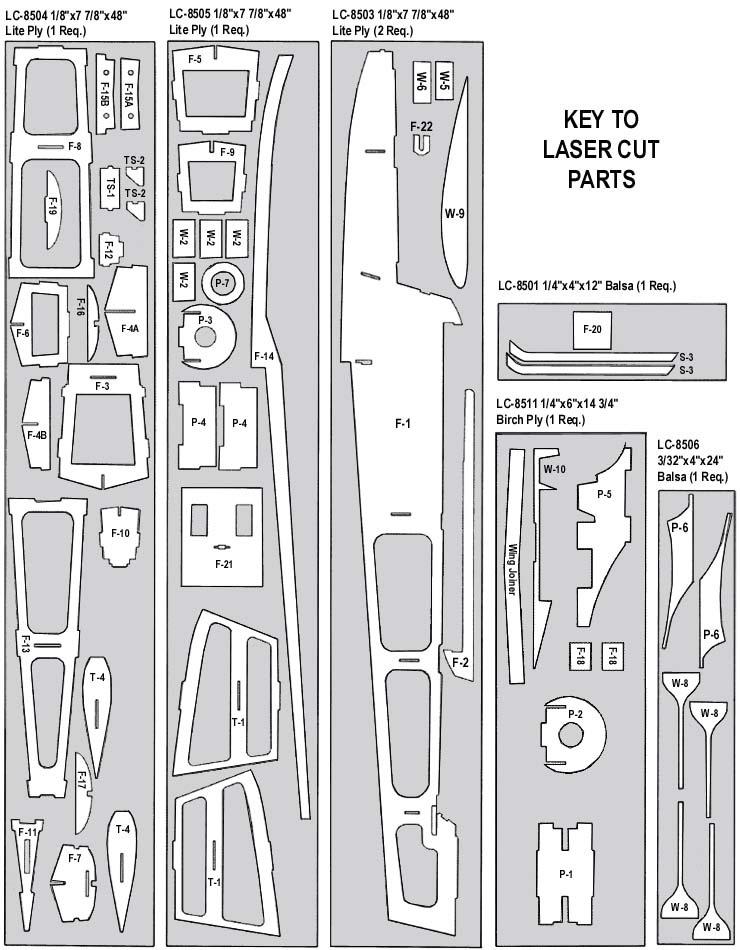
2 Engine Selection Engine choices for the SEALANE are many. The SEALANE has been designed to produce excellent performance when using the recommended engine sizes. Do not use an engine larger than recommended. 2-stroke engines are a perfect choice to power your SEALANE. Any plain-bearing or bearing equipped.40 to.45 sport engine would be a good choice. For example, a great choice would be the Irvine.40 engine. Like all Irvine engines, the.40 is powerful, reliable, and quiet. Whatever engine you choose, take the time to carefully break it in according to the manufacturer s instructions. A good running, reliable engine is a minimum requirement for the enjoyment of this or any R/C model aircraft. The SEALANE can also use a variety of 4-stroke engines. Any 4-stroke engine in the displacement range should provide plenty of power. An important thing to remember is that typical 4-stroke engines have their throttle arms usually located differently than throttle arms on 2-stroke engines. If you want to power this model with a 4-stroke engine, you will likely have to install a new, relocated throttle cable tube. While this is not difficult, it is something to consider when choosing an engine. Covering Material And Waterproofing Your SEALANE has been designed to be completely covered with any of the popular plastic iron on covering materials on the market. These covering materials are waterproof and by carefully overlapping the seams approximately 3/32", your SEALANE will be almost waterproof. The only place on the model where water can enter the fuselage is at the joint where the wing attaches. Our prototype models were made with relatively tight fitting wings, with no additional sealing, and very little water was able to enter the fuselage. Required Tools A selection of glues: A selection of hand tools, such as: Sig Thin CA Sig Medium CA Sig thin CA applicator tips Sig Kwik-Shot Accelerator Sig Epoxy Glue (15 Minute Working Time) Regular size and miniature screwdrivers Regular size and miniature pliers Tweezers or small hemostats Hobby knife with several new #11 blades Sandpaper-assorted grits Sig Modelers T pins Drill Motor 1/16 Drill Bit 3/16 Drill Bit 1/4 Drill Bit Covering Iron Wax Paper Fuel Proof Paint Small Paint Brush Razor saw or Hacksaw blade Pencil Small 90 Square Masking tape and Rubber bands Laser Cut Parts COMPLETE KIT PARTS LIST There are 13 Laser Cut Sheets included in this kit. Use the illustrations on the following pages to identify these parts. Wooden Parts Qty Assembly Name Size & Material Qty Assembly Name Size & Material 1 Fuselage Fuse Nose Top Stringer 1/4 x1/4 x13 Balsa Stick 2 Fuselage Fuse Nose Top Sheet 3/32 x3 x13 Balsa Sheet 28 Fuselage Fuse Bottom Sheet 3/32 x3 x3 Balsa Sheet 1 Fuselage Windshield Top Block 1 x1 x4-1/2 Balsa Block 1 Fuselage Nose Block 4 x2-3/4 x3 Balsa Block 1 Fuselage Windshield Top Sheet 3/32 x1-3/4 x4-1/2 Balsa Sheet 1 Fuselage Fuse Aft Bottom Block 1/4 x2-1/2 x6 Balsa Sheet 2 Fuselage Bolt Block & Firewall Reinf 1/4 x1/4 x7 Balsa Triangle 2 Fuselage Servo Tray Support 1/4 x1/4 x5-1/4 Balsa Stick 1 Fuselage Switch Wire Guide 1/4 x1/4 x1 Spruce Stick 4 Wing Main Wing Spars 1/4 x1/4 x30 Spruce 2 Wing Trailing Edges 1/4 x1/4 x30 Balsa Stick 4 Wing Trailing Edge Sheet 3/32 x1 x30 Balsa Sheet 2 Wing Leading Edges 3/8 x3/8 x27 Balsa Stick 2 Wing Leading Edge Sheet 3/32 x3 x30 Balsa Sheet 2 Wing Leading Edge Sheet 3/32 x3 1/8 x30 Balsa Sheet 8 Wing Center Section Sheet 2 Wing Wing Tip 1-1/2 x1-1/2 x11-1/2 Balsa Triangle 3/32 x3 x12 Balsa Sheet 4 Wing Cap Strip Material 3/32 x1/4 x36 Balsa Stick 4 Wing Tip Float Anchor 1/2 x15/16 x1.15 Hardwood
3 Wooden Parts Continued Qty Assembly Name Size & Material Qty Assembly Name Size & Material 2 Wing Wing Dowel 1/4"x1" Birch Dowel 2 Wing Wing Bolt Plate 1/32"x3/4"x1-1/4" Birch Ply 2 Wing Aileron 440 x1-1/2 x25 Balsa Trailing Edge 2 Wing Torque Rod Bearing Block 440 x1-1/2 x3-29/32 Balsa Trailing Edge 4 Wing Servo Rails 1/4 x1/4 x1-1/4 Spruce Stick 18 Wing Shear Webs 3/32 x2-7/8 x1-5/32 Balsa Sheet 2 Tip Float Tip Float Leading Edge 1/4 x1-3/4 x4-3/4 Balsa Sheet 2 Tip Float Tip Float Trailing Edge 1/4 x1/4 x6 Balsa Stick 12 Tip Float Tip Float Sheet 1/16 x3 x7 Balsa Sheet 3 Pylon Pylon Sheet 3/32 x3 x5 Balsa Sheet 1 Pylon Pylon Tail Block 4 x3-1/4 x4-3/4 Balsa Block 3 Pylon Pylon Engine Fairing Sheet 1 Tail Surfaces Fin Gussets 1/4 x1/4 x12 Balsa Triangle 1 Tail Surfaces Tail Surface Framework 2 Tail Surfaces Tail Surface Framework 1 Tail Surfaces Tail Surface Framework Hardware 1/4 x1/2 x36 Balsa Stick 1 Tail Surfaces Tail Surface Framework 1/4 x1 x9 Balsa Stick 1 Tail Surfaces Tail Surface Framework 1/4 x3 x4-3/4 Balsa Sheet 1/4 x1/4 x4 Balsa Stick. 1/4 x3/4 x36 Balsa Stick 1/4 x1-1/4 x21-3/4 Balsa Stick Qty Assembly Name Size & Material Qty Assembly Name Size & Material 4 Tip Float Tip Float Attach 8-32 x1-1/2 Pan Head Nylon Screw 1 Wing Strip Aileron Horn Set 5 Wing, Fuselage & Pod 16 Wing & Tail Surfaces Left & Right Torque Rods with Connectors Clevis Nylon 2-56 R/C Link 4 Wing & Fuselage 4 Tip Float Tip Float Attach 8-32 Blind Nut 2 Wing Aileron Pushrod 2-56 Pushrod 3 Long Clevis 2-56 Solder Link Hinge Sig Easy Hinge 2 Fuselage Pushrod Housings 24 Nylon Pushrod Housing 2 Fuselage Pushrod 24 Nylon Pushrod 2 Fuselage Pushrod End - Elev. & Rud 2 Fuselage Pushrod End Servos 2 Tail Surfaces Nylon Control Horns 2-56 pushrod 7 long 2-56 pushrod 1-1/2 long 1 Tail Surfaces Elevator Joiner Bent 3/32 Music Wire Sig Medium Control Horns - 1 Left & 1 Right 2 Wing Wing Attach Bolts 1/4-20 x1-1/2 Pan Head Nylon Screw 1 Pylon Pushrod Connector Body 1 Pylon Pushrod Connector Retainer 1 Pylon Throttle Pushrod Housing Misc. Parts 4 Tail Surfaces Control Horns Screws #2 x1/2 Sheet Metal Screw. 1 Fuselage Switch Pushrod 3/64 x5 Music Wire Brass Pushrod Connector Body 1 Pylon Pushrod Connector Screw Molded Nylon Retainer 1 Pylon Threaded Brass Coupler Pushrod Housing 18 1 Pylon Throttle Pushrod Cable 4-40 x1/8 Socket Head Screw 2-56 Brass Coupler Pushrod Cable 18 Qty Assembly Name Size & Material Qty Assembly Name Size & Material 1 Misc Decal Sheet 1 Color Mylar Decal 1 Misc Fuselage Plan 36 x48 Plan sheet A 1 Misc Wing Plan 36 x48 Plan sheet B 1 Misc Instruction Manual Instruction Manual 1 Misc Windshield.015 x4 x8-1/2 Clear Plastic Additional Items (Not included in Kit) Qty Assembly Name Size & Material Qty Assembly Name Size & Material 1 Pylon Motor Mount Dave Brown Mount to Fit Engine Used 8 Pylon Mounting Bolts 6-32 x3/4 Socket Head Cap Screws 8 Pylon Washers 6-32 Washer 4 Pylon Blind Nuts 6-32 Blind Nut 1 Pylon Fuel Tank Sullivan 8 oz. Round Fuel Tank 1 Pylon Spinner Sig 2-1/4 Spinner 1 Pylon Fuel Line Sig Medium Fuel Line 2 All Covering 2 Rolls Iron On Covering + Trim Color 1 Pylon Propeller To Fit Engine Used 1 Pylon Engine.40 to.46 2-cycle or.40 to.50 4-cycle 1 All Radio 4-Channel Radio with 4 Standard Servos Optional Landing Gear Parts (Not included in Kit) 2 Fuselage Radio Protection 3/8 x3 x8 Foam Rubber Qty Assembly Name Size & Material Qty Assembly Name Size & Material 2 Main Landing Gear Main Wheels 3 Wheels 4 Main Landing Gear Wheel Collars 5/32 Wheel Collars

4 Optional Landing Gear Parts (Not included in Kit) Continued Qty Assembly Name Size & Material Qty Assembly Name Size & Material 4 Main Landing Gear Wheel Collars 3/16" Wheel Collars 1 Main Landing Gear Mounting 1/8" Lite Plywood 1 Main Landing Gear Copper Wire.016 Soft Copper Wire 4 Main Landing Gear Main Landing Gear Legs 3/16"x12" Music wire 2 Main Landing Gear Mounting Tubes 3/16 K&S Brass Tube #129 3 Tailwheel Mounting 2-56 x1/2 screws 3 Tailwheel Mounting 2-56 washers 3 Tailwheel Mounting 2-56 nuts 1 Tailwheel Mounting 1/32 Birch Plywood 1 Tailwheel Mounting 1/16 Birch Plywood 1 Tailwheel Tail Wheel 1 Wheel 1 Tailwheel Wheel Collars 1/16 Wheel Collar 1 Tailwheel Axle 1/16 x6 Music Wire
5


6 General Building Notes 1. The SEALANE is recommended for the modeler who has previous building experience. Although the SEALANE is an easy model to build and fly, the instructions were written assuming that the builder has previous experience. As such, procedures such as how to make a proper wood joint or detailed covering instructions are not covered. 2. The first thing that you need to do is mark part numbers on the laser cut parts using the drawings for reference. 3. The laser cut parts have small tabs that keep them attached to the main sheet. You should use your hobby knife to remove the parts from the sheets. If a part is not completely cut through you can use your hobby knife to free it from the sheet. 4. The slight discoloration of the edges of the laser cut parts may be removed by lightly sanding them with 320 grit sandpaper. 5. The wings and the tail surfaces are built directly over the plan. You should cover the plan with wax paper to protect it and to prevent the parts from sticking. BUILDING THE TAIL SURFACES 1. Cover the stabilizer and rudder plan with wax paper. Pin stabilizer parts S-1 and both S-2 s into position on the plan. Using the wood sizes on the plan, cut and glue in place the remainder of the stabilizer parts. Remove the stabilizer from the plan. 2. Pin and glue elevator parts S-3, S-4, and S-5 into position on the plan. Using the wood sizes on the plan, cut and glue in place the remainder of the elevator parts. Remove the elevator from the plan. 3. Pin fin parts R-1 and R-2 into position on the plan. Using the wood sizes on the plan, cut and glue in place the remainder of the fin parts. Remove the fin from the plan. 4. Pin rudder parts R-4 into position on the plan. Using the wood sizes on the plan, cut and glue in place the remainder of the rudder parts. Remove the rudder from the plan. 5. Sand the outside edges of the fin and rudder round. Bevel the leading edge of the rudder. Mark the hinge locations, cut the slots, and temporarily install the hinges (without glue). Set the fin and rudder assembly aside until needed later in construction. 6. Sand the outside edges of the stabilizer and elevators round. Bevel the leading edge of the elevators. Mark and drill the holes in the elevators for the 3/32" joiner wire. Cut a small channel in the leading edge just inboard of the holes for the joiner to fit into, allowing it to be flush with the leading edge. Mark the hinge locations, cut the slots, and temporarily install the hinges (without glue). Set the stabilizer and elevator assembly aside until needed later in construction. BUILDING THE FUSELAGE NOTE: The fuselage is built mostly from laser cut lite plywood parts. You will use the plan as a guide but the fuselage is not built over the plan.


 into the slots in the bottom of the fuselage formers.")
7 7. Glue the fuselage doublers (F-2) to the inside of the fuselage sides (F-1). Be sure that you make a left and a right side. 8. Glue formers F-3 and F-5 into position on the right fuselage side. Use a small square to make sure that the formers are 90 to the fuselage side. 9. Place the left fuselage side into position on the formers and glue in place. 10. Glue formers F-4A and F-4B together as shown on the plan. Now slide the formers into position in the fuselage and glue in place. Gently squeeze the fuselage together at the front and place formers F-6 and F-7 into position. Carefully check to see that the front of the fuselage is not twisted and glue the formers into position. 11. Glue formers F-15A and F-15B together as shown on the plan. Now slide F-15 into position in the fuselage and glue in place. Place F-8 into position on the fuselage. Do this by sliding the tab in the front of F-8 into the notch in F-7 and then pivoting the back end down into position and glue in place. 12. Squeeze the back end of the fuselage together and hold with clothespins or small clamps. Tack glue formers F-9 and F-10 into position. 13. The rearmost end of the fuselage should be 90 to the fuselage top. Loosen the clamps and adjust if required. Now apply glue to bond the rear of the fuselage together. 14. Glue the keel (F-14) into the slots in the bottom of the fuselage formers. Align the step in the keel with formers F-4A and F- 4B. The keel may extend slightly past F-7 and F-10. When the glue is dry, trim the ends of the keel flush with the formers F- 7 and F Glue formers F-16, F-17, and F-19 into position. F-16 and F-17 should be centered left and right and 90 to F-8. F-19 should be 90 to F-3. Glue the 1/4 sq. balsa strip between formers F-7 and F-17. When the glue is dry, trim the balsa strip off flush with the front of F-7 and the rear of F-17.


8 16. Position the wing bolt blocks (F-18) in the fuselage assembly. The top edge should be 1/4" below the top edge of the fuselage side to make room for the 1/4 balsa triangle reinforcements. Glue the bolt blocks in place with epoxy. Cut the 1/4" balsa triangle reinforcements and glue into position. 17. Sand the front edge of F-11 so that it is flush with the front of F-12. Sand the proper angle on the bottom of F-20 and glue it into position on the front of F-12. When the glue is dry, trim the top edge of F-20 flush with the top of F Take one of the 3/32" top front balsa sheets and place into position on the fuselage as shown. The lower edge should touch the fuselage side and the other edge should stick up at an angle. When the sheet is positioned properly you can glue it to the fuselage. When the glue is dry, thoroughly wet the outside of the sheet with an ammonia based cleaner such as Sig s Pure Magic Airplane Cleaner. Allow it to soak in for about 10 minutes. 19. Using the palms of both hands, carefully bend and roll the sheet around the formers. Hold the sheet in position and mark and trim the inboard edge to the centerline of the 1/4" sq. balsa strip. Now glue the sheet into place. NOTE: Depending on the grain and hardness of the sheet, you might find that several small splits open up in the lower edge as you are rolling the sheet into place. This is not a problem. After the sheet is installed, apply a small amount of thin C/A to the cracks and then fill them in with balsa filler such as Hobbico Hobbylite Filler and sand smooth. 20. Now fit, trim, and glue the opposite side top sheeting into place. When the glue is dry, trim and sand the front and rear edges flush with F-7 and F Using a gentle fore and aft motion, carefully sand the fuselage bottom so that the sides and keel match the angle of the formers. 22. Working from F-4 forward, glue the bottom sheet pieces into position. The inboard edge should be centered on the keel (F-14) and the outboard edge should extend past the fuselage side. The first four pieces should fit into position with out trimming the inboard edge. Because of the curvature of the nose of the model, the inboard edge will need to be trimmed to the center of the keel.


9 23. Working rearward from F-4 toward F-10, glue the bottom sheet pieces into position. The inboard edge should be centered on the keel (F-14) and the outboard edge should extend past the fuselage side. Glue the 1/4"x2-1/2"x6" balsa sheet to the bottom of the fuselage behind F-10. When the glue is dry, trim, and sand the bottom sheet flush with the fuselage sides. Continue the "V" shape of the bottom all the way back to the aft end of the model by sanding the bottom of the rear 1/4" sheet. 24. Glue the nose block into position on the front of the fuselage. When the glue is dry, carve and sand the nose block to shape using the following steps. The first thing to do to shape the nose block is to draw the side profile onto the block as shown. Now trim the block to this outline. The outline should be slightly oversized. 25. Now draw the top profile onto the block as shown. Now trim the block to this outline. The outline should be slightly over size. 26. Sand the bottom of the block with a fore and aft motion to match the angle of the "V" on the bottom of the fuselage. You can draw a centerline on the block to assist you. Finally, sand the top corners round and smooth the block all over. Now sand the fuselage smooth all over.


10 BUILDING THE WING NOTE: The wing is built directly on the plan, so cover the plan with wax paper before assembly. These instructions are identical for both the right and left wing panels. 27. Start building the right wing by pinning the lower 1/4" sq. spruce spar to the plan. Also, pin the 1/4" sq. balsa trailing edge to the plan. The inboard ends should be located as shown in the photo. The outboard ends will extend past the last W-4 rib at the wing tip. 28. Place rib W-1 into position. It should be 90 to the building board. Glue W-1 to the spar and trailing edge. Glue the W-4 rib against the outboard side of W Place the two laser cut lite ply shear webs (W-2) into position. Use a scrap of 1/4" balsa from one of the laser cut sheets as a spacer to maintain proper separation between the F-2 s. Glue the F-2 s to the main wing spar and to rib F-1. IMPORTANT NOTE: One end of W-2 is 90 and the other end has a slight angle. The end with the angle should face inboard. Use the front view on the plan to help identify the proper alignment. 30. Place rib W-3 into position. Because of the angle on the inboard end of W-2, the W-3 will not be 90 to the building board but instead it will lean slightly toward the wing tip. Glue the rib to the main spar and to the W-2 shear webs. Be sure to align the shear webs with the top spar notch before gluing. 31. Place parts W-5 and W-6 into position between W-1 and W-3. Note that there is an angle on one end of these parts which should be oriented the same as the W-2 shear webs. 32. Carefully cut the spar joiner slots in ribs W-1 and W-3 as shown. You can use your hobby knife or razor saw to make these cuts. 33. Position the remaining W-4 ribs on the spar and trailing edge and glue in place. These ribs should be 90 to the building board. 34. Place the top 1/4" sq. main spar into position with the inboard end flush with the face of the W-3 rib. Make sure the spar is completely seated in the slots in the ribs and glue the spar in place. The inboard end should be flush with the top of the W- 2 s. Place the 3/32"x1" trailing edge sheet into position and glue it to the top of the 1/4" sq. trailing edge and the wing ribs. 35. Glue the 3/32" balsa shear webs to the back of the main spars in the second and third rib bay as shown. These shear webs have the grain oriented vertically. The parts provided in the kit are slightly long and should be trimmed to achieve a tight fit against the wing ribs. The shear webs should be glued to the spars as well as the wing ribs.


 to the spars and the wing rib at the location shown on the plan.")


11 36. Glue the 3/32" balsa shear webs to the front of the main spars in the second through the eight rib bay as shown. These shear webs have the grain oriented vertically. The parts provided in the kit are slightly long and should be trimmed to achieve a tight fit against the wing ribs. The shear webs should be glued to the spars as well as the wing ribs. Glue the 3/8" sq. balsa leading edge into position at the front of the wing ribs. 37. Glue the hardwood tip float anchors (W-7) to the spars and the wing rib at the location shown on the plan. NOTE: There are four pieces of 3/32" balsa sheet in the kit for sheeting the leading edges of the wing. The 3-1/8" wide sheets are used on the top of the wing. The 3" sheets are used on the bottom of the wing only. 38. Place the 3-1/8" wide 3/32" leading edge sheet into position as shown. The front edge should be completely against the 3/8" sq. leading edge and the ends should extend past the W-3 rib at the inboard end and the W-4 rib at the outboard end. When positioned properly, the sheet should be glued to the 3/8" sq. leading edge only. 39. Roll the sheeting back and down onto the wing ribs. Glue the sheet to all of the wing ribs and to the top spruce spar. Note: You can moisten the outside face of this sheet with an ammonia based cleaner such as Sig s Pure Magic Airplane Cleaner. Allow it to soak in for about 10 minutes before bending the sheet. 40. Glue the 3/32" wing center section sheet into position at the inboard end of the wing between the leading and trailing edge sheet. The outboard end should end at the point shown on the plan with the extra length extending past rib W-3. The front piece can be used with it s full 3" width. The second (rear) sheet needs to be trimmed to the proper width to fit between the first sheet and the trailing edge sheet. 41. Fit the tip float rib cap strip (W-8) into position at the location shown on the plan. Trim the rear end to fit against the trailing edge sheet. When properly fit, glue W-8 into place. 42. Remove the wing from the plan. From the bottom, and using the W-7 s as a drill guide, use a 5/32" drill bit to drill through the tip float rib cap strip (W-8). After drilling the two holes, place the wing panel back onto the building board. Cut the remaining top cap strips from the 3/32"x1/4" balsa strip and glue them into position onto each exposed rib.


 sheet needs to be trimmed to the proper width to fit between the first sheet and")
 into position at the location shown on the plan.")


12 43. Turn the wing panel over, upside down on the building board. Place the 3" wide 3/32" bottom leading edge sheet into position as shown. The front edge should be completely against the 3/8" sq. leading edge and the ends should extend past the W-3 rib at the inboard end and the W-4 rib at the outboard end. When positioned properly, the sheet should be glued to the 3/8" sq. leading edge only. 44. Roll the sheeting back and down onto the wing ribs. Glue the sheet to all of the wing ribs and to the top spruce spar. Note: You can moisten the outside face of this sheet with an ammonia based cleaner such as Sig s Pure Magic Airplane Cleaner. Allow it to soak in for about 10 minutes before bending the sheet. 45. Glue the 3/32" wing center section sheet into position at the inboard end of the wing between the leading and trailing edge sheet. The outboard end should end at the point shown on the plan with the extra length extending past rib W-3. The front piece can be used with it s full 3" width. The second (rear) sheet needs to be trimmed to the proper width to fit between the first sheet and the trailing edge sheet. 46. Fit the tip float rib cap strip (W-8) into position at the location shown on the plan. Trim the rear end to fit against the trailing edge sheet. When properly fit, glue W-8 into place. Cut the remaining cap strips from the 3/32"x1/4" balsa strip and glue into position. 47. Trim the wing sheeting and spars flush with both ends of the wing as shown. Sand the leading edge uniformly round. Sand the wing panel smooth all over. 48. Glue the lite ply tip ribs (W-9) to the outboard end of the wing. 49. Glue the triangular wing tip block into position as shown. The bottom edge should be flush with the bottom of the wing with the excess sticking up above the top of the wing. 50. Trim the top of the wing tip block to match the airfoil shape of the top of the wing ribs and W-9. Then sand the front end round to match the wing leading edge.


13 51. Use epoxy to glue W-10 to the face of W-1. The bottom should be flush with the bottom of the wing and the front should be flush with the front of W-6. Be sure that the pointed part is not blocking the hole between the spars. 52. Use a razor saw or a hack saw to cut away the section of W-10 as shown in the photo. This is the area for the aileron servo and this part of W-10 is easier to remove at this time. 53. Without using glue, test fit the 1/4" birch ply wing joiner into both the left and right wing panels. You may lightly sand these parts if the fit is too tight, however you do want a snug fit without slop or play. Now, using 30 minute epoxy, glue the wing joiner into the slot in the left wing. Wipe any excess epoxy that squeezes out of the joint and allow to dry completely. 54. Use 30 minute epoxy to glue the wing joiner into the right wing and to join the right wing to W Using the plan as a guide, mark the location of the aileron torque rod assembly on the bottoms of the two torque rod bearing blocks. Cut a small notch in the lower leading edge for clearance. Be sure to make a right and left hand parts. Lightly oil the wire to help prevent excess glue from sticking. Carefully glue the aileron torque rods into the blocks by applying a tiny amount of glue to the brass tube bearing and pressing the torque rod into position. Now glue the torque rod blocks to the trailing edge of the wing. 56. Place the wing on the fuselage. Mark a centerline on the fuselage and the wing. Use these marks to align the wing on the fuselage. It must be centered left and right. Now hold the wing tightly in position and use a 1/4" drill bit to drill the wing dowel holes in W-6 & W Use epoxy to glue the 1/4" dowels into the front face of the wing center section. Be sure that the dowels are pointed straight ahead and not angled to the side or up and down. Allow the epoxy to cure. 58. Place the wing back onto the fuselage. Use the centerline marks to establish the proper alignment of the trailing edge. Mark the location of the wing bolts on the top of the wing. The approximate location of the holes is 5/8" forward of the trailing edge and 3/4" in from the fuselage side. Double check the measurements on your model to ensure that the holes will be approximately centered on the plywood wing bolt blocks in the fuselage.


14 59. Hold the wing securely in position on the fuselage and drill 3/16" holes through the wing and into the wing bolt blocks in the fuselage. The drill should be held so that it is angled 90 to the top of the wing surface. Remove the wing from the model. Use a 1/4-20 tap to cut threads in the wing bolt blocks. After removing the tap, coat the threads with thin C/A glue to harden the wood. When dry, run the tap back through the holes to clean out the threads. 60. Glue the 1/32" plywood wing bolt plates to the top of the wing. They should be centered on the 3/16" holes in the wing. Now use a 1/4" drill bit to open up the 3/16" holes in the wing and drill through the wing bolt plates. Use the nylon 1/4-20 x1-1/2" bolts to mount the wing back into position on the fuselage. 61. Trim or sand the bevel on the front of the two ailerons. Mark guidelines on the top, front, and bottom of the aileron. Now use your hobby knife to trim the corners away down to the guide lines. Lightly sand as required to finish the bevel. Hold the ailerons against the wing trailing edge and cut it to the proper length. There should be a 1/16" gap at each end. Also mark the location of the hinges and the aileron torque rod. 62. Cut the slots for the hinges in the wing and ailerons. Drill a 3/32" hole in the leading edge for the aileron torque rod. You will also need to cut a small pocket in the leading edge from the torque rod hole to the inboard end to accept the torque rod wire and allow the aileron to be flush against the trailing edge of the wing. Test hinge the aileron to the wing and make sure that the ailerons move freely. You will need to cut a small angled notch in the bottom of the wing immediately in front and in back of the aileron torque rod to allow it to move forward and backwards, where it exits the bottom of the wing. 63. Sand the wing entirely smooth and set aside for now. 64. Glue the 3/32" balsa sheet to the top of the fuselage between F-3 and F-15. Note that the grain runs left and right. Position the sheet so there is an equal amount of overhang all around. After the glue is dry, trim away the excess sheet and sand it flush on all sides. 65. Glue the 1" sq. x4-1/2" balsa block into position on top of F-9 and against F-3. When the glue is dry, trim and sand the block to the shape shown here and on the plan.
.")


15 BUILDING THE MOTOR PYLON 66. Place the motor mount that you are using on the firewall (P-2). Center the hole in the mount with the hole in P-2. Mark and drill the mounting holes in P-2. Remove the mount from the firewall and install the 6-32 blind nuts. Install the mount on the firewall with the proper screws. If the screws extend past the rear of the firewall they must be cut off to prevent damage to the fuel tank. The motor mount screws should stick out the back of the blind nuts about 3/32". Position the motor on the mount. The front face of the propeller flange on the motor should be 3/34" to 4" forward of the firewall. Mark and drill the motor mount for the screws that you are using. Temporarily bolt the motor to the mount. Check the fit and security and then remove the motor from the mount. 67. Assemble the motor pod from parts P-1, P-2, P-3, and P-4. Use epoxy and make sure that all of the joints are securely glued. Double check that the blind nuts on the firewall are facing the proper direction. Glue the two pieces of 1/4" balsa triangle into the front corners between P-2 and P-4 sides. 68. Assemble the fuel tank following the manufacturers instructions. Use a two line system where one line is the fuel pickup/fill line and one line is the pressure/vent line. Place a bead of silicone rubber to the front of the tank and insert the fuel tank into the pod. The front of the tank should be up against the back of the firewall and the silicone should seal and bond the tank to the firewall. Allow the silicone to dry. 69. Glue the two pylon support parts P-6 to each side of P-5. When the glue is dry, trim away any overhang and sand the front and rear edges round. The top and bottom should not be sanded. Test fit the support to the bottom of the pod.


 over the crankshaft.")


16 70. Mark the firewall for the location of the throttle pushrod. Mark the bottom of the pod where the throttle cable will exit. Now carefully drill holes in these parts making sure that you do not damage the fuel tank.insert the throttle pushrod housing into the pod with about 2" sticking out of the firewall and the remainder sticking out from the bottom of P-1. Glue the housing securely into position. 71. Wrap and glue the 3/32" sheeting around the pod. When the glue is dry, trim the sheet flush with the front of P-2 and the rear face of P Glue the balsa block to P-3. The bottom of the block should be flush with the bottom of P-1. When the glue is dry, sand the block to the cylindrical shape as the pod. 73. Trim and sand the rounded side profile, the top profile and finally round off the corners. Use care not to bend or kink the throttle pushrod where it exits the bottom of the pod. 74. Bolt the motor back on the motor mount. Slide the spinner backup ring (P-7) over the crankshaft. Install the spinner back plate on the motor using the proper adapter and the motors thrust washer and prop nut. If the threads on the crankshaft are not long enough to allow the nut to be tightened without the propeller, use spacers behind the nut as required. Glue several small scraps of 3/32" balsa between the spinner back plate and P-7. This will establish an even spacing between these parts. 75. Cut the bottom piece of the motor fairing from one of the 1/4" balsa sheets provided. The back end should beveled to create a tight fitting joint against P-1. The front edge should be beveled to create a tight fit against P-7. When you are satisfied with the fit, glue the 1/4" balsa sheet into position. 76. Cut, fit and install the remaining 1/4" balsa sheet sides of the fairing. Start at the bottom and work toward the top. The pieces of sheet should be trimmed to achieve a tight fit against the adjacent parts. Build up the sides to the level shown in the photo. When the glue is dry, trim the top edges to allow clearance for the muffler and needle valve and also to provide access to the fuel and vent lines as well as the motor bolts.


17 77. Remove the engine from the mount. Trim and sand the fairing to a smooth shape. Drill a 1/4" drain hole in the bottom of the fairing. This drain hole should be centered left and right and immediately in front of the firewall (P-2). Remove the motor mount from the firewall. The firewall and exposed wood inside the fairing should be painted and sealed with a fuel proof paint such as Sig Butyrate Dope or epoxy. Test fit the motor pylon assembly to the wing. The supports should be a tight fit into the slot in the wing. Drill a 1/16" hole through the wing to allow the throttle pushrod housing to pass through. Now remove the pylon parts and set them aside until it is time to cover the model. 78. Just before joining the wings, you cut away a section of W-10. Take one of the servos and set it on the bottom of the wing. Center it fore and aft over the cut out section of W-10. The servo should be centered left and right. Use a pen to mark around the base of the servo as shown. Remove the servo and use your hobby knife to remove the balsa sheet on the bottom to open up the aileron servo well. Test fit the servo in the opening. There should be about 1/16" clearance between the servo case and the lower wing skin. BUILDING THE FLOATS 79. Lay the parts T-4 over the drawing on the plan. Mark both fore and aft and left and right centerlines on these parts as shown. Mark fore and aft and left and right centerlines on the bottom of the wing. 80. Place the T-4 parts on the bottom of the wing. Align the centerlines on the T-4 s with the marks on the wing and tape T-4 securely to the bottom of the wing. Use a 5/32" drill bit to drill down through the wing and through T-4. Mark the T-4 parts "left" or "right". Install the 8-32 blind nuts into the T-4 s and test fit them by bolting them to the wing. Make sure that the centerlines stay aligned while drilling the holes.


18 81. Glue the parts T-2, T-3 and T-4 to T-1 as shown. They should be 90 to T-1. When the glue is dry, sand the front of the assembly so the front of the formers are flush with T Test fit and glue the 1/4 balsa tip float leading edge into position. The leading edge should be centered left and right and from top to bottom. 83. Take the 1/16" balsa tip float sheet and glue them together as shown on the plan. You will need to make 4 sets of sheeting, two for the left tip float and two for the right tip float. Place the front edge of the sheet against the leading edge sheet and against the front edge of the formers and glue the sheet to the leading edge. When the glue is dry, roll and press the sheet into contact with the formers and glue securely into position. Repeat this process to sheet the opposite side of this tip float and both sides of the other tip float. 84. Trim and sand the sheet flush with the top, bottom and trailing edge of the float. Trim and sand the 1/4" balsa leading edge to the rounded shape shown. Glue the 1/4" sq. balsa trailing edge to the back of the floats and then sand to match the contours of the tip float. 85. Mount the wing onto the fuselage. Use the parts W-11 to fill in the gaps between the leading edge of the wing and the fuselage. There should be a 1/32" gap between the W-11 s and the fuselage to allow for the thickness of the covering. Sand the parts smooth to match the contour of the leading edge. BUILDING THE OPTIONAL LANDING GEAR MOUNTS If you would like to add the optional landing gear to your model, complete the following steps now. However, the landing gear actually can be added to the model after it is completely finished. If you decide not to add it at this time but decide later that you want to, it s not a problem. Note: The parts for the optional material are not included in the kit and must be supplied by the builder. 86. Use the patterns on the plans to cut the wooden landing gear parts. 87. Glue the two F-1C doublers into position on the inside of the left and right fuselage sides. The bottom edge should touch the sheet on the bottom of the fuselage and the front and back should touch the formers.


19 88. Using the locations marked on F-1C, drill two 3/16" holes through each fuselage side. Fit and glue the front and rear landing gear support into position as shown on the plan. The top edges should line up with the bottom of the holes in the fuselage sides. Cut two 4-7/8" lengths of 3/16" brass tube into the holes in the fuselage making sure that the 3/16" wheel collars are in place. The tubes should stick out from the fuselage sides an equal amount. Glue the tubes to the supports and the fuselage sides. The wheel collars can be epoxied to the fuselage side with the screw hole at the top. When the epoxy has cured, sand the excess tube off flush with the fuselage side. 89. Lay the 1/16" plywood parts "A" on the bottom of the rudder and mark a line along the top edge of "A". Use your hobby knife to trim the 1/2" balsa strip from the bottom of the rudder. Use your hobby knife to trim 1/16" of material from the rudder as shown. Use the parts "A" to measure the depth of the cut. The "A" s should be flush with the rudder when properly cut. Glue the two "A" s into place making sure that the top is flush and the gap between them is parallel to the rudder centerline. Sand the plywood parts smooth and round the back end to match the curve on the rudder. PRE-COVER ASSEMBLY 90. Measure and mark a line in the fuselage about 3" down from the edge of the wing opening. Glue the two 1/4" sq. supports to the fuselage immediately below the line. Now glue the lite ply servo tray (F-21) into the fuselage. The tray should sit on top of the balsa supports. You might have to squeeze the fuselage sides together to pull them against the edges of the servo tray. 91. Mount the elevator and rudder servos into the servo tray using the hardware provided with the radio. Mount the switch for the radio into the servo tray. Unless the switch is extra long, you will not use the normal face plate provided with the switch.


20 Mount the elevator and rudder servos into the servo tray using the hardware provided with the radio. Mount the switch for the radio into the servo tray. Unless the switch is extra long, you will not use the normal face plate provided with the switch. The switch lever should have a 1/16" hole in it. Some switches come with this hole, however some do not and if your s does not have the hole, you will have to drill it. 92. Glue the ventral fin (R-3 to the bottom of the fuselage. Make sure it lines up with the aft end of the model so that the rudder will fit properly. Insert the rudder and elevator pushrod housing tubes into the fuselage with about 1-1/2" sticking out from the exit at the fuselage side. Slightly roughen up this end with sandpaper for better adhesion and glue the pushrod housings into the exit. When the glue is dry, trim and sand the housings flush with the fuselage sides. 93. Mark the angle shown on the top of F- 20. Use your hobby knife to trim F-20 back to the marked lines. The angles should extend from the top to the bottom of F-20. Now gently sand F-20 smooth. 94. Make a final test fit of the tail surfaces to the fuselage. Pin the stabilizer and elevator to the fuselage. Pin the fin into position. Cut the lower two hinge slots into the fuselage. Temporarily hinge the rudder to the model and test for proper movement. 95. Cut the windshield pattern from the plan and test fit it to the fuselage. If all looks well, place the pattern on the windshield plastic and carefully cut around it with a new sharp knife. Use tape to temporarily hold the windshield into position and trim if needed for a tight fit.


21 COVERING YOUR MODEL 96. Remove the tail surfaces from the model. Sand the entire model smooth. Any gaps or dents can be filled with a balsa filler such as Hobbico Hobbylite Filler. 97. Cover the model with one of the plastic iron on coverings available. 98. Carefully trim the markings from the decal sheet and apply them to the model. Use the photos on the box and this manual as a guide for placement. FINAL ASSEMBLY 99. Use tape to hold the windshield on the model. Trace around the windshield with a felt tip pen. Remove the windshield from the model and use your hobby knife to remove the covering from the areas where the windshield makes contact with the fuselage. The bare wood can be painted (we used Sig Black Dope) if you would like. Glue the windshield to the fuselage. When the glue is dry, finish the edges of the windshield with trim tape as shown Place the stabilizer into position on the model. Carefully align it so that it is level when viewed from the front and perpendicular to the fuselage centerline when viewed from the top. In addition, the slot for the fin in the stabilizer must line up with the corresponding slot in the fuselage. Use a felt tip pen to trace around the fuselage where it contacts the stabilizer Remove the stabilizer from the model and very carefully trim the covering away from the bottom of the stabilizer to produce wood to wood contact between the stabilizer and the fuselage. DO NOT CUT INTO THE WOOD WHEN REMOVING THE COVERING OR YOU WILL SEVERELY WEAKEN THE STABILIZER. Now glue the stabilizer to the fuselage with epoxy to allow time to align it with the fuselage. Glue the elevator joiner wire into the elevator halves. Install the hinges in the elevator and glue to the stabilizer. Test fit the fin to the top of the stabilizer. Mark and remove the covering where the fin will contact the stabilizer. Now glue the fin into position making sure that the fin is properly aligned. Trim and fit the 1/4" triangle braces at the bottom of the fin. Mark and remove the covering from the fin and stabilizer under the balsa triangle. Cover the outside surface of the balsa triangles with covering material. Now glue the braces into position Hinge the rudder to the vertical fin and fuselage tailpost. When the glue is dry on the hinges, flex the rudder and elevators several times to free up the hinges and to check for proper operation.


 into position on the elevator and rudder pushrods.")

22 103. Assemble the rear ends of the elevator and rudder pushrods, using the 2-56 x7" threaded one-end pushrods. Insert the unthreaded end all the way into nylon tube and thread the pushrod in place, using about 1/2 of the threads. Now thread the nylon clevis onto the reaming pushrod threads Slide the elevator and rudder pushrod into the fuselage from the rear. Use the pushrod and clevis to help establish the location for the elevator and rudder horn. Drill the mounting holes for the horns in the elevator and rudder and install them using the screws provided. Move the control surfaces to check for freedom of movement. You may have to bend the rudder pushrod slightly to prevent binding Solder a solder clevises onto the unthreaded end of the 2-56 x1-1/2" threaded one-end pushrods. These are the servo ends of the rudder and elevator pushrods. Make two of these assemblies, as shown Attach the clevis to the output arms on the rudder and elevator servos. Position the elevator and rudder in the neutral position. Pull the pushrod housings forward against the sides of the threaded rods and mark the housings at the forward end of the threads in the rod. Cut the housing and inner pushrod at the mark. Remove the inner pushrod and cut an additional 1" from the front of the housing. Reinstall the pushrods and screw the front clevis into the pushrods. Attach the clevis to the servos and adjust the length so that the control surfaces are in the neutral position when the servos are centered Slip the lite ply pushrod retainers (F-22) into position on the elevator and rudder pushrods. The F-22 s should be glued to former F-5 and to the pushrod housings Bend the 3/64" dia. x5" switch extension wire and install. Glue the 1/4" sq. spruce retainer to F-21 so that it just touches the wire extension Hinge and install the ailerons on the model. Glue the hinges securely and also glue the torque rod ends into the ailerons. When the glue is dry, flex the ailerons up and down to loosen up the hinges and to check for freedom of movement Remove the covering at the aileron servo rail locations at each end of the aileron servo and glue the 1/4" spruce servo rails to the wing. When the glue is dry, mount the servo with the hardware supplied with the radio.


23 111. Thread the nylon torque rod fittings onto the aileron pushrods. Attach them to the connectors on the aileron torque rods. With the ailerons in the neutral position and the servo centered, mark, cut, and solder the metal clevisie to the front end of the pushrods. Attach the pushrods and adjust the pushrods until the ailerons are in the neutral position when the servo is centered Using 30-minute epoxy, glue the motor pylon support into the slot in the wing center section Glue the motor pod to the top of the motor pylon support using epoxy. Cut away any covering material on the bottom of the pod that would prevent a wood to wood joint. When the epoxy is hard, attach the fuel and vent line to the fuel tank and then bolt the motor & mount into position Take one end of the throttle cable and bend it back on itself 1/2" as shown. Now insert this end of the throttle cable into the threaded brass coupler and solder securely together. Screw the small nylon clevis onto the end of the brass coupler. Feed the throttle cable into the housing and attach the clevis to the throttle arm on the motor Assemble the throttle servo mount from parts TS-1, TS-2, and the two 1/4" sq. spruce strips. Be sure that the TS-2 ends are 90 to the base (TS-1). When the glue is dry, install the throttle servo using the hardware provided with the radio. The servo arm on the throttle servo should be positioned fore and aft when the servo is centered as shown Install the pushrod connector onto the output arm on the throttle servo. Insert the throttle cable into the servo connector and slide the servo down onto the wing. Mark around the base of the throttle mount. Remove the servo and remove the covering from the wing to provide a wood to wood glue joint. Reposition the servo on the wing and glue into position.


 and tighten the wheel collar inside the fuselage to lock it into position.")

24 When the glue is dry, trim the excess length from the throttle cable. Bend the end over about 1/2" and insert the end back through the servo connector so there is a double thickness of cable passing through the connector. Adjust the throttle for full throw and tighten the screw in the servo connector Install the propeller and spinner onto the motor. Install the muffler onto the motor and connect the feed and vent lines. NOTE: The pylon feature found on flying boats such as the Sealane are more sensitive to vibration than a traditional fuselage mounted motor. For this reason it is important that you balance the propeller / spinner assembly to minimize vibration If you are installing the optional landing gear on the model, bend the front main landing gear legs to the shape shown on the plan. Insert the front landing gear into the tube in the model. Position it so that it is vertical (perpendicular to the fuselage centerline) and tighten the wheel collar inside the fuselage to lock it into position. Bend the rear strut to fit against the forward strut. Wrap the connection with copper wire and solder together securely. Now install the wheels and retain them with wheel collars Bend the tailwheel wire to shape. Epoxy parts A, B, and C together with the tail wheel wire sandwiched in the middle. When the glue sets, mount the tail wheel to the axle. Insert this assembly into the slot in the bottom of the rudder. Drill the mounting holes and use 2-56 screws and nuts to hold the tailwheel assembly in place Wrap the airborne battery pack in foam and place it in a small plastic bag for waterproofing. Attach the extension cable that came with your radio to the battery pack. Insert the battery pack into the fuselage and all the way forward in the nose of the model. There should be enough foam to wedge the battery in place and hold it from sliding around Wrap the receiver in foam rubber. Drill a small hole in the top of the fuselage immediately behind the wing. Place the receiver in the fuselage and route the antenna back and out through the hole in the top of the fuselage. The loose end of the antenna should be secured to the top of the fin. Connect the aileron, rudder, elevator, and throttle servos to the receiver. Wrap the receiver in a small plastic bag for waterproofing. Place the receiver in the fuselage just ahead of the servo tray. There should be enough foam to wedge the receiver in place and hold it from sliding around Bolt the wing to the model. Bolt the tip floats in place. Balance the model at the location shown on the plan. This should be done with the fuel tank empty. Add weight to the nose or tail until the proper balance is achieved Set the control throws as shown on the plan. Check that the control surfaces move in the proper direction when you move the sticks on the transmitter Always pre-flight your model thoroughly before each flight. Always range check your radio before each flight. It is your responsibility to verify that your model is airworthy. Always follow established safety guidelines while starting and operating the engine, radio, and while flying the model.


25 FLYING THE SEALANE 125. The Sig SeaLane is a very good handling model and it flies just like traditional land models. If you are flying your model from the land using the optional landing gear you will find that the operation of the Sealane is just like any other tail wheel model. Just remember to check the tightness and security of the landing gear before each flight. Flying the SeaLane from the water is a fantastic experience. When you fly from water you generally have a much larger runway available than you would have if you were flying from the land. Another difference with seaplanes is that you always get to take off and land into the wind. With the large area available on the water, there is no reason for crosswind operations. Taxiing a seaplane is a little different than a land plane. You always want to make sure that your motor is operating reliably before putting your model in the water. Once in the water the model will immediately start to taxi even with the motor at idle. Sometimes this requires you to plan ahead a little as you cannot stop the model on the water with the motor running. You will find that the rudder is effective in controlling the model on the water. If the wind is blowing you will find that it is easier to turn the model into the wind than it is to turn off of the wind. In fact, just like full size seaplanes, you will find that with a strong enough wind that you are unable to turn the model downwind while taxiing. When this is the case you just point the nose into the wind and let it push the model backwards. In full size seaplanes this is known as sailing and is a vital part of learning to fly a full size seaplane. In fact, when getting a seaplane rating in a full size seaplane, transitioning pilots spend most of their time learning to handle the aircraft on the water. So spend some time learning to handle your SeaLane on the water properly. Some water operations require finesse and brute force and power are not usually the best option. Taxi your SeaLane down wind to the take off position. Turn the model directly into the wind. Start the takeoff run by holding the elevators in the full up position. Slowly add throttle. As the model accelerates, it starts forming a bow wave. As speed increases this wave grows larger and moves back along the fuselage. This is the point that some water spray will come up and be blown through the prop. This is during the transition from displacement mode to planing mode. As the model moves faster, water lifts the hull until it is planing like a speed boat. The transition from idle to planing speed happens in just seconds and the model accelerates through this region easily. As the model comes up on the step (planing) reduce the elevator input to neutral. After about two seconds at planing speed gradually feed in some up elevator and the model will lift from the water. In the air, the SeaLane flys like any other model. Gain a little altitude and get the feel of the model. Once at altitude, trim as required to maintain straight and level flight. Reduce the throttle at altitude and see how it handles at slow speed. The SeaLane flies the same type of landing pattern as a traditional land plane. Fly straight and level downwind, parallel to the landing area. When you are abeam of your desired touch down point, slowly reduce the throttle and establish a glide. When you re a little ways past the touchdown point you can turn the model and line it up with the "runway". Continue the approach, holding the wings level, controlling the rate of decent with the throttle. As you approach the water surface, apply a slight amount of up elevator to level the model. Hold the model level or slightly nose up and slowly reduce the power as the model settles on the water. Do not try to make a full stall landing. Instead fly the model onto the water in a level attitude at the lowest possible speed. Your first several landings will probably be a little fast and the model may want to skip back into the air. Be prepared for this and just keep the nose level and let the model settle back into the water as it decelerates. The model will quickly slow down after landing and quickly slow to a taxi speed. We sincerely hope that your SIG SEALANE will provide you with many, many enjoyable flights. We also hope that this has been a pleasurable kit for you to assemble and fly. Please operate your airplane in a safe, responsible manner with constant regard to other flyers, spectators, and property.
FUSELAGE CONSTRUCTION
 FUSELAGE CONSTRUCTION Note: prior to building and gluing on the work surface use protective covering on your building surface. (wax paper or clear wrap) Fit the laser cut Fuselage Front and Fuselage Rear
Stearman PT-17 KIT WARRANTY
 Stearman PT-17 KIT # K-306 Assembly Instructions Version 2 02-17-16 Designed by Tom Herr WARRANTY Sig Manufacturing Co, Inc. guarantees this kit to be free from defects in both material and workmanship
C-180 Builder s Manual
 C-180 Builder s Manual. May 20, 2002 Last revised July 11, 2002 Copyright! 2002 Douglas Binder, Mountain Models www.mountainmodels.com sales@mountainmodels.com (719) 630-3186 1 Required Equipment! Xacto
Citabria Pro. Aerobatic Parkflyer. by Joel Dirnberger
 Citabria Pro Aerobatic Parkflyer by Joel Dirnberger Revision C: December 21, 2004 Citabria Pro Building Instructions Length: Wingspan: Wing Area: Flying Weight: Wing Loading: Functions: Specifications:
LANDING GEAR. 1. Fit landing gear into slots on bottom of fuselage.
 LANDING GEAR 1. Fit landing gear into slots on bottom of fuselage. 4. Use channel-lock pliers to press blind nuts into position (note: drilled hole should be slightly smaller than shaft of blind nut for
MECOA EZ-4061 Trainer
 MECOA EZ-4061 Trainer EZ-4061 is a newly designed, Almost Ready to Fly kit. It is an extremely easy to control trainer with strong construction and excellent aerodynamic performance. This is a great choice
TWEETY 25 INSTRUCTION MANUAL. Almost Ready to Fly Nitro/Electric Aerobat FEATURES SPECIFICATIONS
 TWEETY 25 Almost Ready to Fly Nitro/Electric Aerobat INSTRUCTION MANUAL SPECIFICATIONS FEATURES WINGSPAN: 45.7 (1160mm) LENGTH: 38.6 (980mm) WING AREA: 370 sq in(24 sq dm) FLYING WEIGHT: Approx. 3.3 lbs
SPUNKY ASSEMBLY MANUAL
 SPUNKY ASSEMBLY MANUAL Please read the tips section at the back of this manual regarding the use of laser cut parts. The proper removal and preparation of these parts is important. When laser cut, some
JAMISON SPECIAL. Building Guide
 JAMISON SPECIAL Building Guide WING Mark then drill holes for wing jig rods. Slide Ribs onto jig rods Mark the rib positions on 1/16 x 1 trailing edge, 1/4 x 1/4 leading edge & 1/4 x 1/4 spars Pin ribs
Your kit contains the following parts. Please check your kit for any missing or damaged parts before starting construction.
 Your kit contains the following parts Please check your kit for any missing or damaged parts before starting construction COMPLETE KIT PARTS LIST 1 Plan Sheet #1 1 Plan Sheet #2 2 Decal Sheet 2 White Tissue
Taylorcraft 72 KIT WARRANTY
 Taylorcraft 72 KIT # K-502 Assembly Instructions Revision:02 12-10-13 WARRANTY Alien Aircraft Corp. guarantees this kit to be free from defects in both material and workmanship at the date of purchase.
SZD-10 bis CZAPLA ASSEMBLY MANUAL IN PICTURES
 1 RUDDER Plan and parts: 2 Assembly steps: Photo above: glue together rudder spar, ribs and trailing edge. Clamp spar to a flat surface (chipboard on the photo) and make sure the straight aligment of the
LANIER - Ultimate Pitts - INSTRUCTIONS. Additional Parts Required. (12) 4-40 blind nuts (Dubro #606)
 4-40 blind nuts (Dubro #606)") Additional Parts Required (4) or more channel radio with 7-8 servos..91-2.2 two stroke or 1.20-1.84 four stroke engine Appropriate Master Airscrew prop and Hayes mount for your engine. 3 Tru-Turn spinner
Additional Parts Required (4) or more channel radio with 7-8 servos..91-2.2 two stroke or 1.20-1.84 four stroke engine Appropriate Master Airscrew prop and Hayes mount for your engine. 3 Tru-Turn spinner
Instruction Manual. Specification:
 Instruction Manual H I G Specification: Wingspan: 133 cm (52.3 inches) Length : 104 cm (40.9 inches) Weight : 1830gr Engine : 25-32 two stroke Radio : 4 channel - 4 servo H W I N G KIT CONTENTS: We have
ParkJet Builder s Manual
 ParkJet Builder s Manual Thank you for purchasing the ParkJet. The ParkJet is a profile ducted fan airplane that can be flown in a larger park. The ParkJet was initially designed by Scott Stoops and modified
THE APOGEE A 100-INCH AMA DURATION SAILPLANE FROM DYNAFLITE
 THE APOGEE A 100-INCH AMA DURATION SAILPLANE FROM DYNAFLITE Apogee is the intermediate sailplane designed to be competitive in AMA duration contests. Effective spoilers, rudder and full flying stabilizer
Parts Identification
 We are excited to introduce the Model Aero Aqua Sport. This is an excellent sport flyer, equally at home flying from grass fields, water, or even snow! The unique V-tail gives the Aqua Sport a distinctive
PITTS S2S CONSTRUCTION
 PITTS S2S CONSTRUCTION FUSELAGE CONSTRUCTION 1) Place the right fuselage side over the plan and mark the former positions. Place the left side over the right side and mark the former positions. Glue F1
(Build Instructions)
") (Build Instructions) Specifications * Wingspan: 58cm * Length: 50cm * Flying Weight: 59 grams * Channels: 3 (Rudder Elevator Throttle) * Suggested Receiver: 4Ch Micro * Motor: 8mm GearDrive * Prop: GWS
(Build Instructions) Specifications * Wingspan: 58cm * Length: 50cm * Flying Weight: 59 grams * Channels: 3 (Rudder Elevator Throttle) * Suggested Receiver: 4Ch Micro * Motor: 8mm GearDrive * Prop: GWS
Note - the nose ribs and are thinner than the main ribs. These nose ribs will use a thinner rib cap than the ribs. This is per design.
 Stabilizer rev 1.2 The SE5a stabilizer is the heartbeat of the tail and is recreated like the full scale version. All tail pieces depend on the stabilizer. It uses the steel fittings, pulleys, inspection
RYAN STA SAFETY PRECAUTIONS. "Sport Scale E-Power ARF" For Intermediate and Advanced Fliers. This radio control model is not a toy!
 RYAN STA "Sport Scale E-Power ARF" For Intermediate and Advanced Fliers. SAFETY PRECAUTIONS This radio control model is not a toy! First-time builders should seek advice from people with model building
Building Tips This model can be built using the following types of adhesives:
 Page 1 Building Tips This model can be built using the following types of adhesives: Epoxy (with or without microballons) Odorless cyanoacrylate (CA) with accelerator UHU Creativ for Styrofoam (or UHU
Dandy Sport Builder s Manual
 Dandy Sport Builder s Manual Thank you for purchasing the Dandy Sport. The Dandy Sport has been designed as an easy to build aileron trainer. Take your time and enjoy building this plane. Specifications:
84 WING SPAN MESSERSCHMITT BF-109
 84 WING SPAN MESSERSCHMITT BF-109 (COPYRIGHT PROTECTED 2014) ALL RIGHTS RESERVED MEISTER 84 ME-109 SIERRA GEAR UPDATE PLEASE NOTE: THE MAIN GEAR MOUNTING PLATE FROM SIERRA IS NOT SQUARE. YOU HAVE TO ROUND
Switchback Sport Builder s Manual
 Switchback Sport Builder s Manual Thank you for purchasing the Switchback Sport. The Switchback Sport has been designed for the novice to intermediate pilot who wants a plane with good performance that
105" TIGER MOTH ARF INSTRUCTION MANUAL VERSION 1.0
 105" TIGER MOTH ARF INSTRUCTION MANUAL VERSION 1.0 Step 1. Installation of the aileron servos 1) Mount aileron servo to servo mounting blocks with servo s screws. Install servo mounting plate with screws.
30% Edge 540T Almost Ready to Fly
 Lanier R/C 30% Edge 540T Almost Ready to Fly WARNING! THIS IS NOT A TOY! THIS IS NOT A BEGINNERS AIRPLANE This R/C kit and the model you will build from it is not a toy! It is capable of serious bodily
LARK. Classic Legal Precision Stunter RSM DISTRIBUTION. presents. Charles Mackey. Wing Area 570sq. Wingspan 52.
 RSM DISTRIBUTION presents LARK By Charles Mackey Photo _ Bob Hunt Classic Legal Precision Stunter Wingspan 52 Length 39.5 Wing Area 570sq Motor 35-46 www.rsmdistribution.com Page 2 Thank you for purchasing
Thank you for your purchase of the Lee Ulinger, FoamtanaS, Yak-55, or Extra 330 3D Depron foam, Aerobatic airplane.
 Thank you for your purchase of the Lee Ulinger, FoamtanaS, Yak-55, or Extra 330 3D Depron foam, Aerobatic airplane. Tools you will need to build Recommended additional items: #11 hobby knife Motor: Hacker
Taylorcraft Indoor / Cul-De-Sac Flyer
 Taylorcraft Indoor / Cul-De-Sac Flyer Taylocraft Specifications Wingspan: 28.0 in. Wing Area: 117 sq. in. Weight (Ready to Fly): 3.0 3.1 oz. Wing Loading: 3.7 3.8 oz. / sq. ft. LIABILITY RELEASE In that
LANIER - Double Trouble - INSTRUCTIONS. Tail 1 T1 ¼ Balsa 1 T2 ¼ Balsa 2 T3 ¼ Balsa 1 T4 ¼ Balsa 1 T5 ¼ Balsa 1 T6 ¼ Balsa 2 J1 ¼ Balsa 2 J2 Lite ply
 Tail 1 T1 ¼ Balsa 1 T2 ¼ Balsa 2 T3 ¼ Balsa 1 T4 ¼ Balsa 1 T5 ¼ Balsa 1 T6 ¼ Balsa 2 J1 ¼ Balsa 2 J2 Lite ply Other Parts 2 Aluminum Gear 1 3/32 Music wire tail skid 2 Elevator and J-plane joiner wire
BUILDING THE A6M2 ZERO
 BUILDING THE A6M2 ZERO Product Support (Do Not Remove From Department) TOP FLITE MODELS, INC CONGRATULATIONS' You now own the most accurate R/C Stand-Off Scale kit ever produced We at Top Flite hope that
INSTRUCTION MANUAL BOOK.
 INSTRUCTION MANUAL BOOK. SPECIFICATION Wingspan : 164 cm 64.57in. Length : 135 cm 53.15 in. Weight : 3.3kg 7.26 lbs. Servo : 7 servos. Radio : 4 channels. Engine : 61 cu.in-2 stroke. 91 cu.in-4 stroke.
Super Sky Surfer 2000 Assembly Instructions
 Super Sky Surfer 2000 Assembly Instructions Note: Plug and Play version of the Sky Surfer comes with fuselage pre-glued and motor/servos installed. If you wish to route antennas or wires through the tail,
Instruction Manual book
 Instruction Manual book ITEM CODE BH53. SPECIFICATION Wingspan : 1,250mm 49.21 in. Length : 930mm 36.61in. Weight : 1.1kg 2.42 Lbs. Parts listing required (not included). Battery: 3 CELLS-LI-POLY-11.1V-2,500
SwitchBack Senior. SwitchBack Senior Specifications
 SwitchBack Senior SwitchBack Senior Specifications Wingspan: 55.4 in. Length: 41 in. Wing Area: 597 sq. in. Weight (Ready to Fly): 34 to 37 oz. Wing Loading: 8.2 to 8.9 oz. / sq. ft. Version 1.05, March
FLITZEBOGEN-2 Assembly instructions
 FLITZEBOGEN-2 Assembly instructions Trim the end of the fuselage to the length of 925mm from the nose. Be careful to avoid splitting the carbon fibers. Sand the base of the stab mount in preparation for
RESolution V2 Manual
 RESolution V2 Manual Note for the German Manual: Yellow Bottle thick CA Pink Bottle Med CA Blue tube 5 minute Epoxy Green tube 90 Minute Epoxy Construction of the Fuselage Step 1: Cover the plan with a
LANIER Dominator INSTRUCTIONS
 ADDITIONAL EQUIPMENT NEEDED TO COMPLETE YOUR DOMINATOR 500 General 3.2 to 4.2 Size two stroke R/C engine, muffler, and engine mount Gas or glow fuel line Minimum of 4 channel radio set required (4-5) 70
STEP 1 STEP 2 STEP 3. Page 2
 INSTRUCTION MANUAL Congratulations on your purchase of the Bullet ARTF - the first Almost Ready to Fly version of this classic lowwinger. Based on the original and timeless Bullet design, the new Ripmax
Combat plane for Open B Lanier R/C Inc. P.O. Box 458 Oakwood, GA Phone Fax copyright 2003 Lanier R/C
 Combat plane for Open B Lanier R/C Inc. P.O. Box 458 Oakwood, GA. 30566 Phone 770 532 6401 Fax 770 532 2163 copyright 2003 Lanier R/C Important information: Please inspect the plane before beginning to
Fokker Dr1 Master Instructions
 Fokker Dr1 Master Instructions Rev 1 Congratulations on your new project. This Dr1 kit is the finest to date. The construction of the plane is similar and exactly like the original. Take your time and
RSM DISTRIBUTION Presents
 RSM DISTRIBUTION Presents MOSQUITO By Jack Sheeks Photo _ Jack Sheeks Semi Scale Twin Stunter Wing Span: 58" Length: 37-3/4 Area: 579 sq. in. Engine: Two.35 -.40 www.rsmdistribution.com Call (951) 678
FUJI FA-200 AERO SUBARU
 FUJI FA-200 AERO SUBARU SEMI SCALE SPORT MODEL AERO SUBARU Assembly and Operations Manual Please review this manual throughly Before assembling or Operating The AERO SUBARU Semi scale sport model We ve
Piper Cherokee /3 scale. Construction Manual
 Piper Cherokee 140 1/3 scale Construction Manual STAB CONSTRUCTION 1. Remove foam cores from cradle and place on flat surface. Inspect pieces before you epoxy halves together making sure leading and trailing
High performance 90mm fiberglass jet
 High performance 90mm fiberglass jet Assembly manual For intermediate and advanced fliers only! Specs Wingspan: 1255mm Fuselage length: 1250mm Flying weight: 2600-3000g Wing area: 22.6 dm² Wing loading:
Pfalz E1 Monoplane 48 EZ Build Version
 Pfalz E1 Monoplane 48 EZ BUILD Pfalz E1 Monoplane 48 EZ Build Version R/C Scale Model Instructions CONTACT INFORMATION Designed by M.K. Bengtson Prototype by Robert Hoffman Manufactured and Distributed
Parkflyer F6F Hellcat
 Parkflyer F6F Hellcat Page 1 of 19 MOLT MODELS Background Design Philosophy When I was first introduced to this hobby seventeen years ago I saw my first WWII warbird and I was hooked. Several years later
Assembly Manual / Airframe 65 Vyper SAFETY in Assembly SAFETY in Flying
 1 Assembly Manual / Airframe 65 Vyper Thank you for purchasing this 3DHobbyShop ARF RC aircraft. If you have any issues, questions, concerns or problems during assembly, please contact our tech department
TIGER SHARK-40 ARF ASSEMBLY MANUAL
 TIGER SHARK-40 ARF ASSEMBLY MANUAL Kangke Industrial USA, Inc. 65 East Jefryn Blvd. Deer Park NY 11729 http://www.kangkeusa.com E-mail: info@kangkeusa.com Tel: 1-877-203-2377 Fax: 1-631-274-3296 Congratulations!
10. Wing prep and subassembly
 Date Section Objective: Construct and fabricate the sub-assemblies of the wing panel. Required Parts: Wing left 11gal PN104-300, Wing right 1gal PN104-400, Wing left 15 gal option PN104-322, Wing right
HIGH-END TECHNOLOGY. Electric ducted fan Starfighter
 HIGH-END TECHNOLOGY RC Electric ducted fan Starfighter First we want to thank and congratulate you with your decision in buying one of our Kits. The Starfighter puts together very easily so there is not
Hand-made Almost Ready to Fly R/C Model Aircraft ASSEMBLY MANUAL
 Hand-made Almost Ready to Fly R/C Model Aircraft ASSEMBLY MANUAL Specifications Wingspan -----------------------.148 cm--------------- 58.3 in. Wing area ----------------------- 3474sq. cm ---- 538.4sq
Specifications Wingspan: 43cm Flying Weight: 33 grams (with battery) Channels: 3 Suggested Receiver: 4Ch Micro Motor: 7mm Brushed Geardrive
 Channels: 3 Suggested Receiver: 4Ch Micro Motor: 7mm Brushed Geardrive") Specifications Wingspan: 43cm Flying Weight: 33 grams (with battery) Channels: 3 Suggested Receiver: 4Ch Micro Motor: 7mm Brushed Geardrive Airframe Kit (Included Contents) * Airframe Parts Sheets (Depron)
Specifications Wingspan: 43cm Flying Weight: 33 grams (with battery) Channels: 3 Suggested Receiver: 4Ch Micro Motor: 7mm Brushed Geardrive Airframe Kit (Included Contents) * Airframe Parts Sheets (Depron)
Millennium RC presents The New and Improved (now even easier to build and cover!) SSX X-Trainer Build Kit
 SSX X-Trainer Build Kit") Millennium RC presents The New and Improved (now even easier to build and cover!) SSX X-Trainer Build Kit Wing span: Approx. 42 Wing Area: 504 sq. in. Wing Loading: 6.71 oz/ sq. ft. Introduction: The Slow
Millennium RC presents The New and Improved (now even easier to build and cover!) SSX X-Trainer Build Kit Wing span: Approx. 42 Wing Area: 504 sq. in. Wing Loading: 6.71 oz/ sq. ft. Introduction: The Slow
BUILDING THE FUSELAGE FRAME 6
 KIT 305 DHC-2 BEAVER COPYRIGHT 2011 BY PAUL K. GUILLOW, INC. WWW.GUILLOW.COM Before starting the construction of your model, study the plan and construction procedure carefully so that you will have a
MUSTANG P-51. Hand-made Almost Ready to Fly R/C Model Aircraft ASSEMBLY MANUAL
 MUSTANG P-51 Hand-made Almost Ready to Fly R/C Model Aircraft ASSEMBLY MANUAL Specifications Wingspan---------------------------------------- 60.5 in----------------------- 153.7cm. Wing area-------------------------------------
INSTRUCTIONS FOR FINAL ASSEMBLY
 MS: 11 INSTRUCTIONS FOR FINAL ASSEMBLY Graphics and specfications may change without notice. Specifications: Wingspan -------------------------------------------- 156 cm, 61.42 in. Wing area ---------------------------------
4. Bevel the LE face of HS1-HS11 to match the horizontal stab leading edge sweep angle.
 BEFORE YOU BUILD 1. Unroll each sheet of the plans. Roll them inside out so that they will lie flat on the building surface. 2. Assemble the tools that you will need to build each section so that they
96 WING SPAN SPITFIRE (COPYRIGHT PROTECTED 2014) ALL RIGHTS RESERVED
 ALL RIGHTS RESERVED") 96 WING SPAN SPITFIRE (COPYRIGHT PROTECTED 2014) ALL RIGHTS RESERVED GENERAL INSTRUCTIONS Should you elect to use the recommended Door Skin, which is 1/8 mahogany plywood measuring 36 x 88. Have it cut
96 WING SPAN SPITFIRE (COPYRIGHT PROTECTED 2014) ALL RIGHTS RESERVED GENERAL INSTRUCTIONS Should you elect to use the recommended Door Skin, which is 1/8 mahogany plywood measuring 36 x 88. Have it cut
Hobby Lobby Zip Supplementary instructions Please refer to the included drawings while using these assembly instructions
 Materials needed: 15 or 30 minute epoxy Medium CA Masking tape Scotch tape Servo Tape Wax paper Tools Needed: Pencil or marker Flat building surface Hobby knife or razor blade 7/64" or 3mm drill bit 3/16"
LANIER R/C. Shrike WARNING! THIS IS NOT A TOY! THIS IS NOT A BEGINNERS AIRPLANE LIMITED WARRANTY
 Shrike WARNING! THIS IS NOT A TOY! THIS IS NOT A BEGINNERS AIRPLANE This R/C kit and the model you will build from it is not a toy! It is capable of serious bodily harm and property damage. It is your
CARL GOLDBERG PRODUCTS, LTD.
 Pitts Monster Aerobatic flying just doesn't get any better than this Pitts ARF. The classic lines of a biplane coupled with the radial cowl, add excitement to the maneuvers you love, knife edge, split
AT channel 6 servos
 Wing Span: Wing Area: Fuselage Length: Flying weight: Power system: Radio: 60.7in/1540mm 561 sq in/36.3 sq dm 44.1in/1120mm 6.9 Ibs/ 3100g 46(2C0/71(4C) 5 channel 6 servos AT6-46 INSTALLING AILERONS Begin
WE GET PEOPLE FLYING AT-6
 TM WE GET PEOPLE FLYING AT-6 Texan.60 ARF ASSEMBLY MANUAL Specifications Wingspan:... 67.5 in (1714mm) Length:... 48 in (1219mm) Wing Area:... 706 sq in (45.54 sq dm) Weight:... 7 8.5 lb (3.17 3.85 kg)
Corvus Racer Colour schemes. AeroPlus RC Copyright 2013 All Rights Reserved
 Corvus Racer 540 59 Item No:A E050003 Specifications WING SPAN: 59"(1500mm) LENGTH: 54.1"(1374mm) WING AREA: 654sq.in.(42.2sq.dm.) FLYING WEIGHT: 4.6 5.3lbs(2000 2300g) Electric:Brushless outrunner 8Oz.
INCLUDED IN THIS KIT: SPECIFICATION: NEEDED BUILDING TOOLS: REQUIRED EQUIPMENT:
 Please review this entire manual before beginning assembly. By doing so it will help you better understand each step as you progress in the actual building of your kit, and you will do a better job in
E-AERO EPP PITTS KIT From BP HOBBIES. Parts Included in kit
 E-AERO EPP PITTS KIT From BP HOBBIES Parts Included in kit Thank you for purchasing the BP Hobbies/E-aero EPP Pitts. Please take the time to read through the instruction manual before beginning the build.
S.E.5a (Build Instructions)
") S.E.5a (Build Instructions) Specifications Wingspan: 38 cm Length: 31cm Flying Weight: 41 Channels: 3 (Rudder Elevator Throttle) Suggested Receiver: 3Ch Brick Motor: 7mm Geared Motor Airframe Only Kit
S.E.5a (Build Instructions) Specifications Wingspan: 38 cm Length: 31cm Flying Weight: 41 Channels: 3 (Rudder Elevator Throttle) Suggested Receiver: 3Ch Brick Motor: 7mm Geared Motor Airframe Only Kit
MOUNTAIN MODELS P-51 Mustang. 1/12 Scale Electric Park Flyer. Copyright Mountain Models
 1 MOUNTAIN MODELS www.mountainmodels.com P-51 Mustang 1/12 Scale Electric Park Flyer Wingspan: 37, Wing Area: 254 sq. in., Weight: 15 to 19.5 oz Instructions Version 1.4, May 23, 2007 Kit Contents: 2 1.
LoLo. A sporty parkflyer with an Old Timer flair! Designed by: Tres Wright Kitted by: Park Scale Models
 LoLo A sporty parkflyer with an Old Timer flair! Designed by: Tres Wright Kitted by: Park Scale Models http://www.parkscalemodels.com/ Assembly Instructions General Information The laser cutting process
90 WING SPAN P-51D MUSTANG (COPYRIGHT PROTECTED 2014) ALL RIGHTS RESERVED
 ALL RIGHTS RESERVED") 90 WING SPAN P-51D MUSTANG (COPYRIGHT PROTECTED 2014) ALL RIGHTS RESERVED GENERAL INSTRUCTIONS This design is basically an enlargement of the very popular fun scale Mustang 60 Size. You can build it light
90 WING SPAN P-51D MUSTANG (COPYRIGHT PROTECTED 2014) ALL RIGHTS RESERVED GENERAL INSTRUCTIONS This design is basically an enlargement of the very popular fun scale Mustang 60 Size. You can build it light
SPORTSTER BY FRED TUXWORTH
 SPORTSTER BY FRED TUXWORTH For those who like gas models to look like real airplanes, this sturdy performer is just about tops. Best -looking model of the year Biplane wings may be fitted. This gives you
Assembly Instructions STINGER
 STINGER 120 ARF Important Information: Please inspect the plane before beginning to assemble to make sure you are happy with it. After assembly has begun you cannot return the kit. If you find a problem
1/2a Control Line Trainer Engine: Cox Black Window.049
 Designed by Bill Osborne & Peter Justin Drawn by Heman Lee 1/2a Control Line Trainer Engine: Cox Black Window.049 This model airplane is made from foam-board that can be purchased at any art-supply store
Eva. Extremely Versatile Airframe
 Eva Extremely Versatile Airframe Eva Specifications Length: 32 Weight (without battery): ~12oz. Revision History Date Revision Notes/Comments 6/3/05 Document initial creation. Thank you for purchasing
Building Instructions P-51 BF109
 Building Instructions P-51 BF109 Sport model for.015 engines. Legal for SSC Warbird Lanier R/C Inc. P. O. Box 458 Oakwood, Ga. 30566 Copyright 2004 Lanier R/C Inc. Important information: Please inspect
Hot Stik ARF WARNING. Copyright 2005 Carl Goldberg Products LTD CARL GOLDBERG PRODUCTS, LTD.
 Hot Stik ARF INSTRUCTIONS WARNING A radio-controlled model is not a toy and is not intended for persons under 16 years old. Keep this kit out of the reach of younger children, as it contains parts that
77 Edge 540 ARF WARNING
 77 Edge 540 ARF INSTRUCTIONS WARNING A radio-controlled model is not a toy and is not intended for persons under 16 years old. Keep this kit out of the reach of younger children, as it contains parts that
INCLUDED IN THIS KIT: SPECIFICATION: NEEDED BUILDING TOOLS: REQUIRED EQUIPMENT:
 Please review this entire manual before beginning assembly. By doing so it will help you better understand each step as you progress in the actual building of your kit, and you will do a better job in
LANIER - Giles % - INSTRUCTIONS
 Additional Parts Required (4) or more channel radio with 4 servos..25 -.36 two stroke or.40 -.52 four stroke engine Appropriate Master Airscrew prop and Hayes mount for your engine. 2-1/2 Tru-Turn spinner
12. Wings, Flaps, Ailerons and Struts
 12. Wings, Flaps, Ailerons and Struts Fit Aileron Hinges Reference: Drawing 20270K2 Photo 12.1 Parts Required: 2007092 Aileron LS 200809N Aileron RS 2001394 Hinge 3/16 A1 (4) 2001694 Hinge Pin (4) PH0059N
Introducing The Cloud Models Westland Whirlwind
 Produced by Cloud Models,Deopham Road,Morley,Wymondham, Norfolk,NR18 9AA E-mail sales@cloudmodels.com web site cloudmodels.com Introducing The Cloud Models Westland Whirlwind By Tricks Thank you for purchasing
Corvus Racer CC
 Corvus Racer 540 35CC Item No:L-G035008 Specifications Wing Span Length Wing Area Flying Weight Glow Gasoline Electric Radio mm mm 1200sq in (77.4sqdm) 9.9-12lbs(4.5-5.5kg) 91-1.20(2C) 1.10-1.40(4C) 20-40cc
HIGH-END TECHNOLOGY. Electric ducted fan rafale
 HIGH-END TECHNOLOGY RC Electric ducted fan rafale First we want to thank and congratulate you with your decision in buying one of our Kits. The Rafale puts together very easily so there is not much explanation
I hope you enjoy the Spirit as much as I have. Scott DeTray Model Aero
 We are excited to introduce the Model Aero Spirit. Inspired by the magnificent Northrop Grumman B-2 Spirit Stealth Bomber, the Spirit is a great flyer, on land or water. It tracks like an arrow and is
This pictorial document contains assembly recommendations including some fit and finish details that will be helpful when building this airplane
 This pictorial document contains assembly recommendations including some fit and finish details that will be helpful when building this airplane Problems found with this kit and a flight performance review
TIGER MOTH 120 ASSEMBLY INSTRUCTIONS
 TIGER MOTH 120 ASSEMBLY INSTRUCTIONS SPECIFICATIONS Wing Span: Length: Radio: Flying Weight: 1920mm 1580mm 4 channel with 6 servos 4200g AILERON ASSEMBLY 1 Start by removing the servo cover from the bottom
Cobra X Q Construction Tips Construction: Bel y pan
 Cobra X Q Construction Tips : The white plastic in this kit is high impact styrene. It can be painted with most types of coatings if light coats are applied this is necessary due to the thickness of the
Fokker D8 Master Instructions
 Fokker D8 Master Instructions Rev 1 Congratulations on your new project. The Fokker D8 is a marvellous subject that highlights the success of a monoplane design. The construction of the plane is similar
Pfalz E1 48. R/C Scale Model Instructions CONTACT INFORMATION. The Pfalz E1 was designed by M.K. Bengtson Prototype by Jack Richardson
 Pfalz E1 48 Pfalz E1 48 R/C Scale Model Instructions CONTACT INFORMATION The Pfalz E1 was designed by M.K. Bengtson Prototype by Jack Richardson Manufactured and Distributed by: Bengtson Company e mail:
Magpie. Foam Trainer. Magpie Specifications
 Magpie Foam Trainer Magpie Specifications Length: 34in. Wingspan (SF): 46in. Wing Area (SF): 414in 2 Wingspan (SP): 40in. Wing Area (SP): 360in 2 Weight (without battery): 12oz. Thank you for purchasing
SGTalon s Enterprise-A Foamie Build Guide. SGTalon s. Enterprise. Enterprise--A. Assembly Instructions
 SGTalon s Enterprise SGTalon s Enterprise--A Enterprise Assembly Instructions Page 1 4-13-2013 SGTalon s Enterprise *******Recommended Hardware******** 2.6oz 250w Motor and Speed Control with 8x6 prop
EXTRA 330SC 60CC. Item No:H G Specifications cc gas DA50,DA60, DLE55, DLE60(twin), 3W55. Description
, 3W55. Description") EXTRA 330SC 60CC Item No:H G060011 Specifications Wing Span Length Wing Area Flying Weight Gasoline Radio Description Carbon Fibre : 92" (2347mm) 84 1/2 " (2060mm) 1526.8 sq in(98.5sq dm) 16 17lbs(7300
EXTRA 330SC 60CC Item No:H G060011 Specifications Wing Span Length Wing Area Flying Weight Gasoline Radio Description Carbon Fibre : 92" (2347mm) 84 1/2 " (2060mm) 1526.8 sq in(98.5sq dm) 16 17lbs(7300
Super Chipmunk CARL GOLDBERG PRODUCTS, LTD. Instructions
 Super Chipmunk Instructions Another loop, roll and then a plunge earthward into a dive trailing billowing white clouds of smoke. Perilously close to the ground it pulls out and zooms a few hundred feet
REX SCOUT D6. R/C Scale Model Instructions
 REX SCOUT D6 R/C Scale Model Instructions CONTACT INFORMATION The Rex Scout D6 was designed by M.K. Bengtson Manufactured and Distributed by: Bengtson Company e-mail: sales@aerodromerc.com Web Site: www.aerodromerc.com
Nieuport 11 Bebe. R/C Scale Model Instructions. CONTACT INFORMATION The Nieuport 11 Bebe was designed by Peter Rake and M.K.
 Nieuport 11 Bebe 49 Nieuport 11 Bebe R/C Scale Model Instructions CONTACT INFORMATION The Nieuport 11 Bebe was designed by Peter Rake and M.K. Bengtson Manufactured and Distributed by: Bengtson Company
67 Edge 540 ARF WARNING
 67 Edge 540 ARF INSTRUCTIONS WARNING A radio-controlled model is not a toy and is not intended for persons under 16 years old. Keep this kit out of the reach of younger children, as it contains parts that
INSTRUCTION MANUAL. Suitable for Electric or I.C. Engine Power
 INSTRUCTION MANUAL Suitable for Electric or I.C. Engine Power Congratulations on the purchase of your Irvine Tutor 40 II Radio Control Model Aircraft. Please take some time to carefully read these instructions
Assembly Instructions. Stinger 120. Almost Ready to Fly
 Stinger 120 Almost Ready to Fly Important Information: Please inspect the plane before beginning to assemble to make sure you are happy with it. After assembly has begun you cannot return the kit. If you