INSTRUCTION MANUAL BOOK.
|
|
|
- Spencer Perkins
- 5 years ago
- Views:
Transcription


1 INSTRUCTION MANUAL BOOK. SPECIFICATION Wingspan : 164 cm 64.57in. Length : 135 cm in. Weight : 3.3kg 7.26 lbs. Servo : 7 servos. Radio : 4 channels. Engine : 61 cu.in-2 stroke. 91 cu.in-4 stroke. Made in Vietnam.
2 This instruction manual is designed to help you build a great flying aeroplane. Please read this manual thoroughly before starting assembly of your CHIPMUNK. Use the parts listing below to identify all parts. WARNING. Please be aware that this aeroplane is not a toy and if assembled or used incorrectly it is capable of causing injury to people or property. WHEN YOU FLY THIS AEROPLANE YOU ASSUME ALL RISK & RESPONSIBILITY. If you are inexperienced with basic R/C flight we strongly recommend you contact your R/C supplier and join your local R/C Model Flying Club. R/C Model Flying Clubs offer a variety of training procedures designed to help the new pilot on his way to successful R/C flight. They will also be able to advise on any insurance and safety regulations that may apply. TOOLS & SUPPLIES NEEDED. Thick cyanoacrylate glue. 30 minute epoxy. 5 minute epoxy. Hand or electric drill. Assorted drill bits. Modelling knife. Straight edge ruler. 2mm ball driver. Phillips head screwdriver. 220 grit sandpaper. 90 square or builder s triangle. Wire cutters. Masking tape & T-pins. Thread-lock. Paper towels. PARTS LISTING. FUSELAGE ASSEMBLY (1) Fuselage. WING ASSEMBLY (1) Right wing half with pre-installed aileron. (1) Left wing half with pre-installed aileron. Some more parts... Tail section assembly Some more parts. HARDWARE PACK COWLING. Landing gear... SUGGESTION. To avoid scratching your new airplane, do not unwrap the pieces until they are needed for assembly. Cover your workbench with an old towel or brown paper, both to protect the aircraft and to protect the table. Keep a couple of jars or bowls handy to hold the small parts after you open the bag. NOTE. Please trial fit all the parts. Make sure you have the correct parts and that they fit and are aligned properly before gluing! This will assure proper assembly. CHIPMUNK ARF is hand made from natural materials, every plane is unique and minor adjustments may have to be made. However, you should find the fit superior and assembly simple. The painted and plastic parts used in this kit are fuel proof. However, they are not tolerant of many harsh chemicals including the following: paint thinner, C/A glue accelerator, C/A glue debonder and acetone. Do not let these chemicals come in contact with the colors on the covering and the plastic parts. (1) Vertical stabilizer with preinstalled rudder. (1) Horizontal stabilizer with preinstalled elevator halves. 2


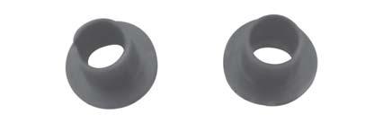
3 SAFETY PRECAUTION. + This is not a toy + Be sure that no other flyers are using your radio frequency. + Do not smoke near fuel + Store fuel in a cool, dry place, away from children and pets. + Wear safety glasses. +The glow plug clip must be securely attached to the glow plug. + Do not flip the propeller with your fingers. + Keep loose clothing and wires away from the propeller. + Do not start the engine if people are near. Do not stand in line with the side of the propeller. + Make engine adjustments from behind the propeller only. Do not reach around the spinning propeller. INSTALLING THE AILERON- FLAP SERVOS. 1. Install the rubber grommets and brass eyelets onto the aileron and flap servo. C/A glue C/A glue 3


4 Flap servo tray. Aileron servo tray C/A glue C/A glue Servo tray. Bottom side. Flap. Aileron. 2. Using a modeling knife, remove the covering servo tray. 4


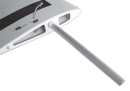
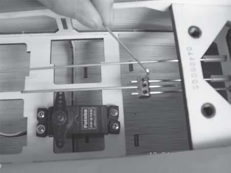
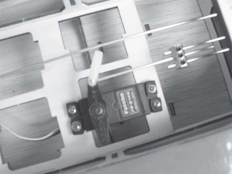
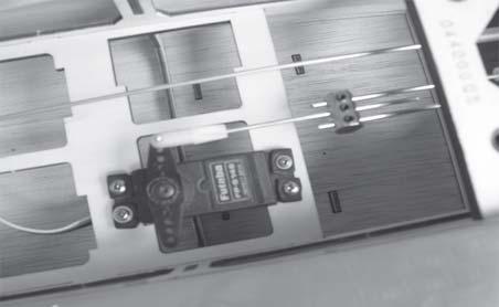
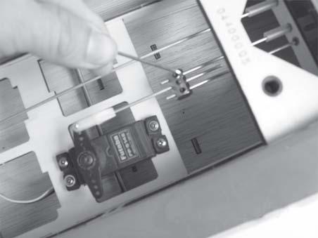
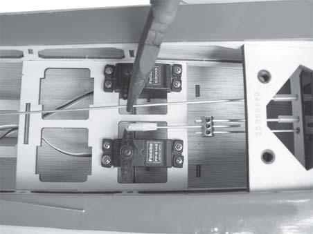
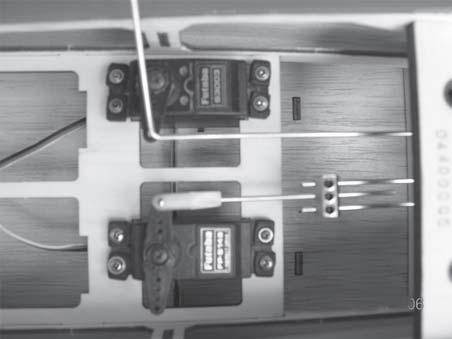
5 3. Drill 1,5mm pilot holes through the block of wood for each of the four mounting screws provided with the servo. Install servo into aileron servo tray as same as picture below. 2 x 10 mm. Secure 4. Using the thread as a guide and using masking tape, tape the servo lead to the end of the thread: carefully pull the thread out. When you have pulled the servo lead out, remove the masking tape and the servo lead from the thread. Electric wire. Thread. 5. Instal servo tray with aileron servo into the wing as same as picture below. 6. Install servo tray with flap servo in to the wing as same as picture below. Aileron. Flap. 5


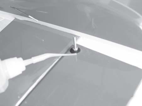
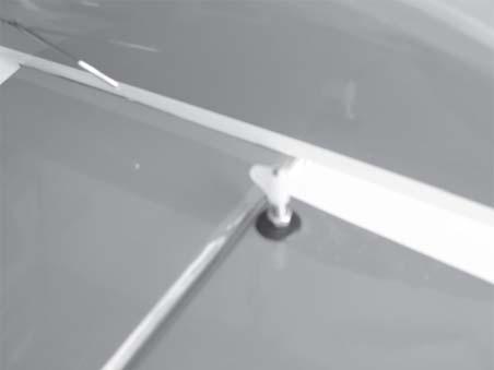
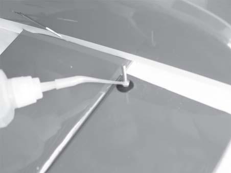
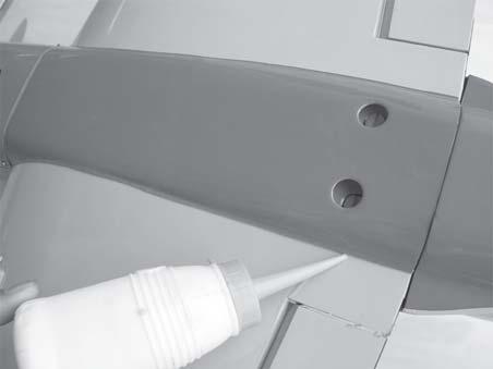
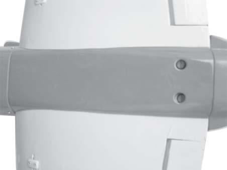
6 Flap. Repeat the procedure for the other wing half. Aileron. 3. Install control horn as same as picture below. INSTALLING THE AILERON - FLAP SERVO CONTROL HORN. 1. Using a ruler & pen to draw a straight line as below picture. 4. Install aileron control horn as same as picture below. straight line. Nilon control clasp. 3 x 50mm. M3 lock nut. 2. Drill through 1 hole with 6 mm diameter the aileron using the control horn as a guide and screws the control horn in place. 6


7 aileron control horn Control horn. 5. Install Flap control horn as same as picture below as same as the way of aileron. Nilon control clasp. 3mm x 50mm. M3 lock nut. C/A glue. Flap. C/A glue. 7


8 4. Locate one nylon servo arm, and using wire cutters,remove all but one of the arms. Using a 2mm drill bit, enlarge the third hole out from the center of the arm to accommodate the aileron pushrod wire. 5. Using pliers, carefully make a 90 degree bend down at the mark made. Cut off the excess wire, leaving about 4mm beyond the bend. M2 clevis. Snap keeper. M2 lock nut. 6. Insert the 90 degree bend down through the hole in the servo arm. Install one nylon snap keeper over the wire to secure it to the arm. Install the servo arm retaining screw and remove the masking tape from the aileron. INSTALLING THE AILERON LINKAGES. Flap. 1. Working with the aileron linkage for now, thread one clevis onto one of the threaded wires. 2. Attach the clevis to the outer hole in the control horn. Install a silicone tube on the clevis. 3. Plug the aileron servo into the receiver and center the servo. Install the servo arm onto the servo. The servo arm should be perpendicular to the servo and point toward the middle of the wing. Aileron. Bend. Cut. Aileron. 8


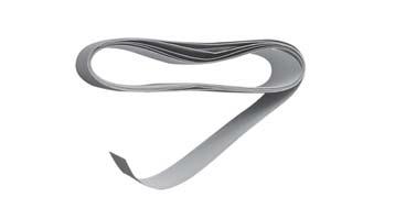
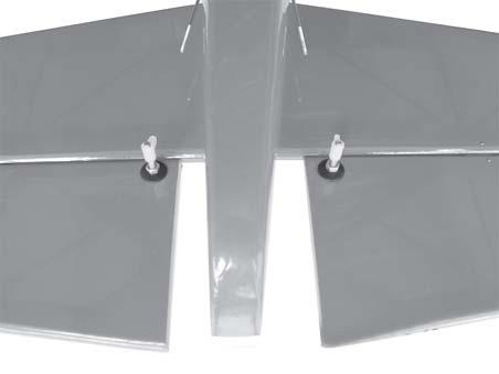
9 Repeat the procedure for the other wing half. Bottom side Flap Aileron finishing Flap. Top side JOINING THE WING HALVES. 1. Location the aluminium wing dihedral brace. Flap. 2. Using a modeling knife, remove the covering wing. Flap. 3. Test fit the dihedral brace into each wing haft. The brace should slide in easily. If not, use 220 grit sand down the edges and ends of the brace until it fits properly. 9


10 Remove covering. Masking tape. Apply masking tape. Epoxy glue. Aluminium brace. Dowel brace. 10

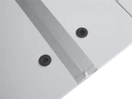

11 Bottom side. INSTALLING LANDING GEAR. Mark point. 3x12mm. Wing bolt plate. Insert the wing bolt plate. 11


12 Mark point Remove covering. 1mm drill bit. 12


13 C/A glue. Apply masking tape 13


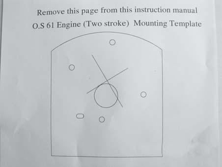

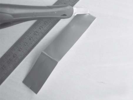
14 Cut See pictures below: ENGINE MOUNT. 3.5x25mm. 4x25mm. 14

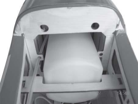
15 FUEL TANK. INSTALLING THE STOPPER ASSEMBLY 1. The stopper has been pre-assembled at the factory. 2. Using a modeling knife, cut one length of silicon fuel line (the length of silicon fuel line is calculated by how the weighted clunk should rest about 8mm away from the rear of the tank and move freely inside the tank). Connect one end of the line to the weighted clunk and the other end to the nylon pick up tube in the stopper. 3. Carefully bend the second nylon tube up at a 45 degree angle (using a cigarette lighter). This tube will be the vent tube to the muffler. 4. Carefully bend the third nylon tube down at a 45 degree angle (using a cigarette lighter). This tube will be vent tube to the fueling valve. When the stopper assembly is installed in the tank, the top of the vent tube should rest just below the top surface of the tank. It should not touch the top of the tank. 15


16 5. Test fit the stopper assembly into the tank. It may be necessary to remove some of the flashing around the tank opening using a modeling knife. If flashing is present, make sure none of it falls into the tank. Do not secure the tank into place permanently until after balancing the airplane. You may need to remove the tank to mount the battery in the fuel tank compartment 6. When satisfied with the alignment of the stopper assembly tighten the 3mm x 20mm machine screw until the rubber stopper expands and seals the tank opening. Do not over tighten the assembly as this could cause the tank to split. 7. Using a modeling knife, cut 3 lengths of fuel line 150mm long. Connect 2 lines to the 2 vent tubes and 1 line to the fuel pickup tube in the stopper. 8. Feed three lines through the fuel tank compartment and through the pre-drilled hole in the firewall. Pull the lines out from behind the engine, while guiding the fuel tank into place. Push the fuel tank as far forward as possible, the front of the tank should just about touch the back of the firewall. Blow through one of the lines to ensure the fuel lines have not become kinked inside the fuel tank compartment. Air should flow through easily. Fuel tank. 9. To secure the fuel tank in place, apply a bead of silicon sealer to the forward area of the tank, where it exits the fuselage behind the engine mounting box and to the rear of the tank at the forward bulkhead. 16


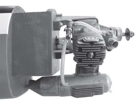
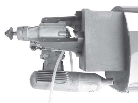
17 INSTALLING THE ENGINE. Fuel tank tray. Locate the long piece of wire used for the throttle pushrod. One end of the wire has been pre-bend in to a Z bend at the factory. This Z bend should be inserted into the throttle arm of the engine when the engine is fitted onto the engine mount. Fit the engine to the engine mount using the screws provided. 12cm. 17


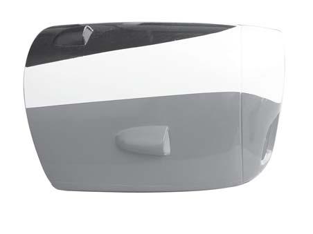
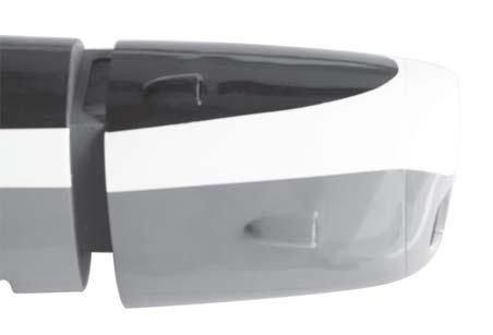
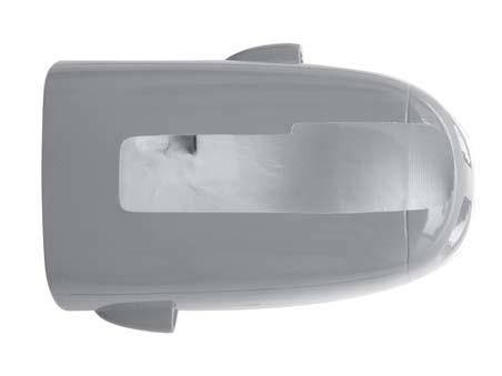
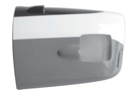
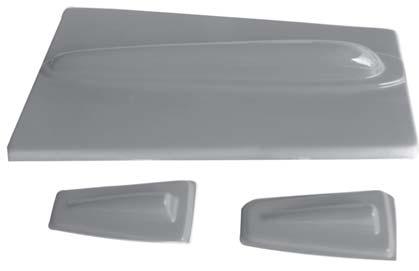
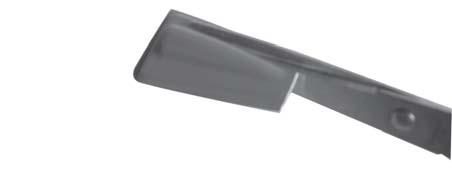
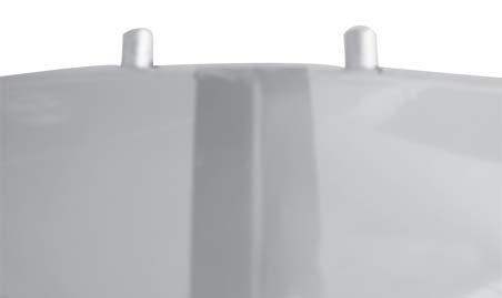
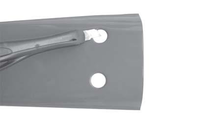
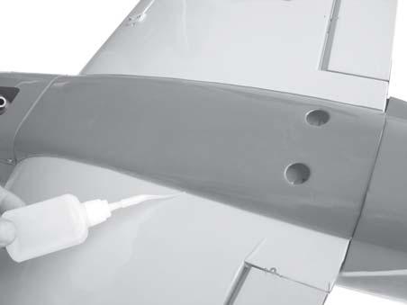
18 COWLING. 1. Slide the fiberglass cowl over the engine and line up the back edge of the cowl with the marks you made on the fuselage. Trim and cut. 18


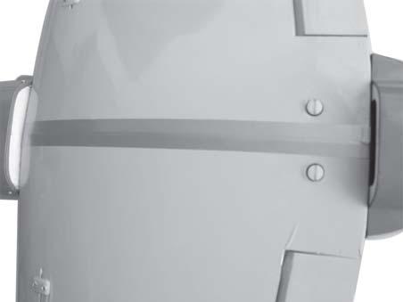
19 3 x 10 mm. 2. While keeping the back edge of the cowl flush with the marks, align the front of the cowl with the crankshaft of the engine. The front of the cowl should be positioned so the crankshaft is in nearly the middle of the cowl opening. Hold the cowl firmly in place using pieces of masking tape. 3. Slide the cowl back over the engine and secure it in place using four wood screws. 4. Install the muffler and muffler extension onto the engine and make the cutout in the cowl for muffler clearance. Connect the fuel and pressure lines to the carburetor, muffler and fuel filler valve. 19


20 INSTALLING THE SPINNER. ELEVATOR INSTALLATION. 3 x 12mm. 1. Install the rubber grommets and brass collets into the elevator servo. Test fit the servo into the servo tray. Install the spinner backplate, propeller and spinner cone. The spinner cone is held in place using two 3mm x 12mm wood screws. 2. Mount the servo to the tray using the mounting screws provided with your radio system. 20


21 C/A glue C/A glue Elevator servo. HORIZONTAL STABILIZER INSTALLATION. C/A glue Horizontal stabilize installation. See picture below. 1. Using a modeling knife, cut away the covering from the fuselage for the stabilizer and remove it. Remove covering. C/A glue 21


22 2. Draw a center line onto the horizontal stabilizer. Then slide the horizontal into the fuselage. Center line. 4. Remove the stabilizer. Using the lines you just drew as a guide, carefully remove the covering from between them using a modeling knife. When cutting through the covering to remove it, cut with only enough pressure to only cut through the covering it s self. Cutting into the balsa structure may weaken it. This could lead to possible failure during flight. Top side 3. Mark the shape of the vertical on the left and right sides onto the horizontal stabilizer using a left-tip pen. Remove covering. Top side Bottom side. 22


23 M3 lock nut. 3mm x 30mm. Nilon control clasp. Control horn of elevator. 5. When you are sure that everything is aligned correctly, mix up a generous amount of 30 minute epoxy. Apply a thin layer to the top and bottom of the stabilizer mounting area and to the stabilizer mounting platform sides in the fuselage. Slide the stabilizer in place and re-align. Double check all of your measurements one more time before the epoxy cures. Remove any excess epoxy using a paper towel and rubbing alcohol and hold the stabilizer in place with T-pins or masking tape. Mark point Bottom side. Drill 1 hole with 6 mm diameter. Top side. C/A glue Top side. ELEVATOR CONTROL HORN PUSHROD INSTALLATION. Elevator control horn install as same as the way of aileron control horn. Please see pictures below. 23


24 C/A glue. Top side ELEVATOR PUSHROD INSTALLA- TION. C/A glue. Elevator pushrod. Elevator pushrod. Elevator control horn. 24


25 Cut. Elevator servo. Bend and cut. VERTICAL STABILIZER. 25


26 Hinge. Pen. 1. Using a modeling knife cut away the covering from the top of the fuselage and remove it. 2. Slide the rudder into the fuselage as same as picture below. 4. Now, remove the rudder and using a modeling knife, carefully cut just inside the marked lines and remove the film of the rudder. Just as you did with the horizontal stabilizer, make sure you only press hard enough to cut the film, not the balsa rudder. Remove covering. Remove covering. Remove covering. 5. Put the vertical stabilizer back in place. Using a triangle, check to ensure that the vertical stabilizer is aligned 90 degree to the horizontal stabilizer. 3. Mark the shape of the vertical on the left and right side on the rudder using a felt-tip pen. Horizontal Stabilizer. 90º Vertical Stabilizer. 26


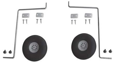
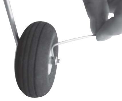
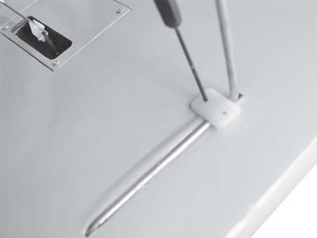
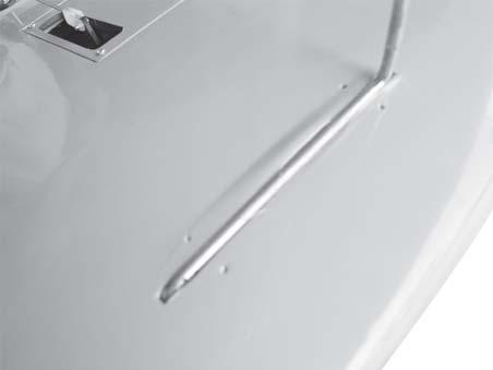
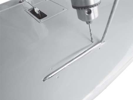
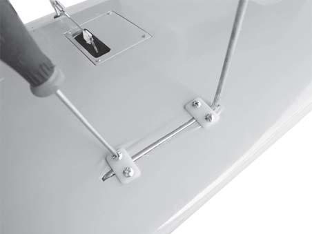
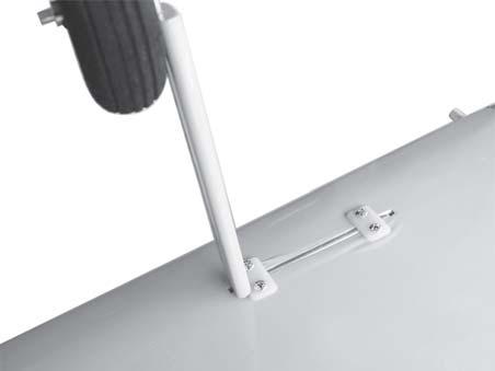
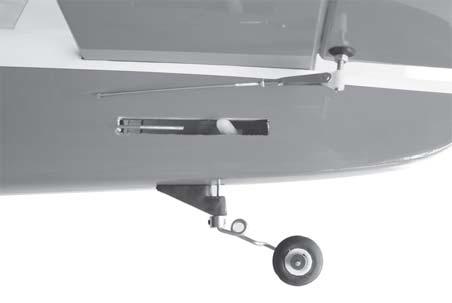
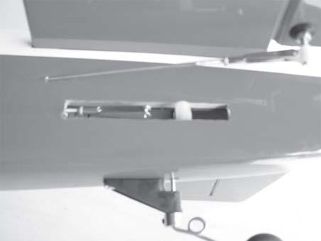
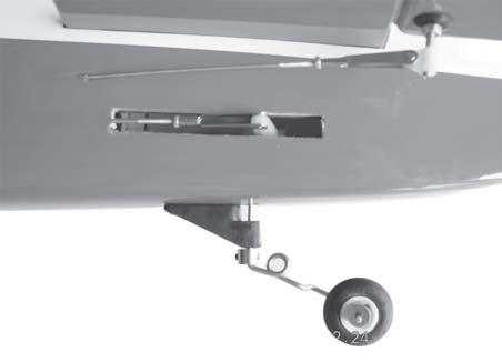
27 6. When you are sure that everything is a aligned correctly, mix up a generous amount of 30 minute epoxy. Apply a thin layer to the slot in the mounting platform and to the vertical stabilizer mounting area. Apply epoxy to the lower rudder hinge. Set the stabilizer in place and re-align. Double check all of your measurements once more before the epoxy cures. Remove any excess epoxy using a paper towel and rubbing alcohol and hold the stabilizer in place with T-pins or masking tape. Allow the epoxy to fully cure before proceeding. 1. Set the tail wheel assembly in place on the plywood plate. The pivot point of the tail wheel wire should be even with the rudder hinge line and the tail wheel bracket should be centered on the plywood plate. 2. Using a pen, mark the locations of the two mounting screws. Remove the tail wheel bracket and drill 1mm pilot holes at the locations marked. Epoxy glue. Mark point C/A glue MOUNTING THE TAIL WHEEL BRACKET. 3 X 12 mm. 3. Secure the tail wheel bracket in place using three 3mm x 12mm wood screws. Be careful not to overtighten the screws. 27


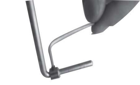
28 RUDDER CONTROL HORN THE INSTALLATION. Rudder pushrod Rudder control horn C/A glue. Mark made. Top of elevator. Remove covering. 18mm. Carefully make a 90 degree bend down at the mark made. Cut off the excess wire, leaving about 20mm beyond the bend. 20 mm Cut. secure. Bend 90 degree. 28


29 Epoxy glue. Push C/A glue Rudder pushrod Control horn rudder 29


30 RUDDER PUSHROD INSTALLA- TION. Rudder pushdrod Bend and cut. Elevator pushdrod Elevator pushdrod Cut. Cut. Rudder servo. 30


31 Remove covering. C/A glue Bottom side Top side Epoxy glue. Covered wood filler piece Bottom side Push Insert covered wood filler piece as picture C/A glue 31


32 C/A glue Epoxy glue. Remove covering. C/A glue C/A glue Remove covering. INSTALLING THE THROTTLE PUSHROD. 1. Install one adjustable metal connector through the third hole out from the center of one servo arm, enlarge the hole in the servo arm using a 2mm drill bit to accommodate the servo connector. Remove the excess material from the arm. 32


 Cut out the switch hole")


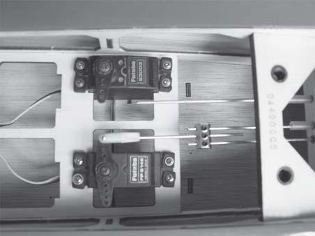
33 Servo arm. Connector. After installing the adjustable metal connector apply a small drop of thin C/A to the bottom nut. This will prevent the connector from loosening during flight. Rudder servo. throttle servo. Elevator servo. INSTALLING THE SWITCH. 1) Cut out the switch hole using a modeling knife. Use a 2mm drill bit and drill out the two mounting holes through the fuselage side. 2) Secure the switch in place using the two machine screws provided with the radio system. 33


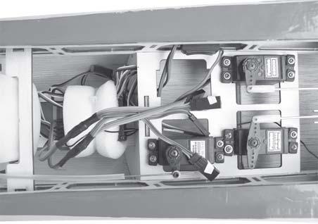
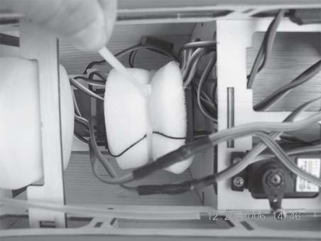
34 Tie wrap. Tie wrap. Switch. Battery. INSTALLING THE RECEIVER AND BATTERY. 1. Plug the servo leads and the switch lead into the receiver. You may want to plug an aileron extension into the receiver to make plugging in the aileron servo lead easier when you are installing the wing. Plug the battery pack lead into the switch. 2. Wrap the receiver and battery pack in the protective foam to protect them from vibration. Use a rubber band or masking tape to hold the foam in place. 3. Position the battery pack and receiver behind the fuel tank. Use two tie wraps to hold the battery and receiver securely in place as pictures below Do not permanently secure the receiver and battery until after balancing the model. 4. Using a 2mm drill bit, drill a hole through the side of the fuselage, near the receiver, for the antenna to exit. 34

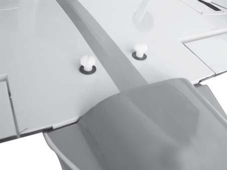

35 Receiver. Wing bolt. WING ATTACHMENT. See picture wing attach to fuselage. 35


36 Epoxy glue. Cut. C/A glue 36
37 BALANCING. 1. It is critical that your airplane be balanced correctly. Improper balance will cause your plane to lose control and crash. THE CENTER OF GRAVITY IS LOCATED 100mm BACK FROM THE LEADING EDGE OF THE WING. 2. Mount the wing to the fuselage. Using a couple of pieces of masking tape, place them on the top side of the wing 100 mm back from the leading edge, at the fuselage sides. 3. Turn the airplane upside down. Place your fingers on the masking tape and carefully lift the plane. Accurately mark the balance point on the top of the wing on both sides of the fuselage. The balance point is located 100mm back from the leading edge. This is the balance point at which your model should balance for your first flights. Later, you may wish to experiment by shifting the balance up to 10mm forward or back to change the flying characteristics. Moving the balance forward may improve the smoothness and arrow- like tracking, but it may then require more speed for take off and make it more difficult to slow down for landing. Moving the balance aft makes the model more agile with a lighter and snappier feel. In any case, please start at the location we recommend. With the wing attached to the fuselage, all parts of the model installed ( ready to fly), and empty fuel tanks, hold the model at the marked balance point with the stabilizer level. Lift the model. If the tail drops when you lift, the model is tail heavy and you must add weigh* to the nose. If the nose drops, it is nose heavy and you must add weight* to the tail to balance. *If possible, first attempt to balance the model by changing the position of the receiver battery and receiver. If you are unable to obtain good balance by doing so, then it will be necessary to add weight to the nose or tail to achieve the proper balance point. CG 100MM 2) Turn the airplane upside down. Place your fingers on the masking tape and carefully lift the plane. CONTROL THROWS. 1. We highly recommend setting up a plane using the control throws listed. 2. The control throws should be measured at the widest point of each control surface. 3. Check to be sure the control surfaces move in the correct directions. Ailerons : 15mm up 15mm down Elevator : 15mm up 15mm down Rudder : 35mm right 35mm left Ailerons Control PRE-FLIGHT CHECK. 1. Completely charge your transmitter and receiver batteries before your first day of flying. 2. Check every bolt and every glue joint in your plane to ensure that everything is tight and well bonded. 3. Double check the balance of the airplane. 4. Check the control surface. 5. Check the receiver antenna. It should be fully extended and not coiled up inside the fuselage. 6. Properly balance the propeller. We wish you enjoy. 37
38 38
Instruction Manual book
 Instruction Manual book ITEM CODE BH53. SPECIFICATION Wingspan : 1,250mm 49.21 in. Length : 930mm 36.61in. Weight : 1.1kg 2.42 Lbs. Parts listing required (not included). Battery: 3 CELLS-LI-POLY-11.1V-2,500
Instruction Manual book
 Instruction Manual book ITEM CODE: BH50. SPECIFICATION Wingspan : 1,600 mm 62.99 in. Length : 1,230 mm 48.43 in. Weight : 2.5 kg 5.5 Lbs. Radio : 06 channels. Servo : 07 servos. Electric Motor : ( 02pcs
Instruction Manual. Specification:
 Instruction Manual H I G Specification: Wingspan: 133 cm (52.3 inches) Length : 104 cm (40.9 inches) Weight : 1830gr Engine : 25-32 two stroke Radio : 4 channel - 4 servo H W I N G KIT CONTENTS: We have
PERCIVAL P-56 PROVOST
 Instruction Manual Book. PERCIVAL P-56 PROVOST OLEO STRUTS LANDING GEAR. ALL BALSA - PLY WOOD CONSTRUCTION. COVERED WITH ORACOVER Glow and EP 95% ALMOST READY TO FLY SPECIFICATION: - Wingspan: 1,644mm
HAWKER HURRICANE. Instruction Manual Book 95% ALMOST READY TO FLY. Item code: BH147. SPECIFICATION
 Instruction Manual Book Item code: BH147. HAWKER HURRICANE ALL BALSA - PLY WOOD CONSTRUCTION. COVERED IN A HEAT-SHRINK FILM WITH PRINTED. 95% ALMOST READY TO FLY SPECIFICATION Wingspan: 1,520 mm (59.84
NOORDUYN NORSEMAN. Instruction Manual Book 95% ALMOST READY TO FLY. Item code: BH157. SPECIFICATION
 Instruction Manual Book Item code: BH157. NOORDUYN NORSEMAN ALL BALSA - PLY WOOD CONSTRUCTION. COVERED WITH ORACOVER. 95% ALMOST READY TO FLY SPECIFICATION - Wingspan: 1840 mm (72.44 in). - Length: 1180
BUCKER BU 131 JUNGMANN ALL BALSA - PLY WOOD CONSTRUCTION. COVERED WITH ORACOVER
 Instruction Manual Book. BUCKER BU 131 JUNGMANN ALL BALSA - PLY WOOD CONSTRUCTION. COVERED WITH ORACOVER Glow and EP 95% ALMOST READY TO FLY SPECIFICATION: - Wingspan: 1,850 mm (72.83 in). Length: 1,660
INSTRUCTIONS FOR FINAL ASSEMBLY
 MS: 11 INSTRUCTIONS FOR FINAL ASSEMBLY Graphics and specfications may change without notice. Specifications: Wingspan -------------------------------------------- 156 cm, 61.42 in. Wing area ---------------------------------
PROCTOR. Instruction Manual Book 95% ALMOST READY TO FLY. Item code: BH154. SPECIFICATION ALL BALSA - PLY WOOD CONSTRUCTION. COVERED WITH ORACOVER
 Instruction Manual Book PROCTOR Item code: BH154. ALL BALSA - PLY WOOD CONSTRUCTION. COVERED WITH ORACOVER 95% ALMOST READY TO FLY SPECIFICATION Wingspan: 1,360 mm (53.54 in). Length: 1,480 mm(58.27 in).
MUSTANG P-51. Hand-made Almost Ready to Fly R/C Model Aircraft ASSEMBLY MANUAL
 MUSTANG P-51 Hand-made Almost Ready to Fly R/C Model Aircraft ASSEMBLY MANUAL Specifications Wingspan---------------------------------------- 60.5 in----------------------- 153.7cm. Wing area-------------------------------------
Hand-made Almost Ready to Fly R/C Model Aircraft ASSEMBLY MANUAL
 Hand-made Almost Ready to Fly R/C Model Aircraft ASSEMBLY MANUAL Specifications Wingspan -----------------------.148 cm--------------- 58.3 in. Wing area ----------------------- 3474sq. cm ---- 538.4sq
FAIREY ALBACORE. Instruction Manual Book. Glow and EP. Item code: BH % ALMOST READY TO FLY SPECIFICATION:
 Instruction Manual Book. FAIREY ALBACORE ALL BALSA - PLY WOOD CONSTRUCTION. COVERED IN A HEAT-SHRINK FILM WITH PRINTED. Glow and EP 95% ALMOST READY TO FLY SPECIFICATION: - Wingspan: 1,693mm (66.65in).
JUNKERS JU87- B2 STUKA
 Instruction Manual Book Item code: BH169. JUNKERS JU87- B2 STUKA OLEO STRUTS LANDING GEAR. ALL BALSA - PLY WOOD CONSTRUCTION. COVERED IN A HEAT-SHRINK FILM WITH PRINTED. 95% ALMOST READY TO FLY SPECIFICATION:
A S S E M B L Y M A N U A L
 A S S E M B L Y M A N U A L Kit features. Ready-made minimal assembly & finishing required. Ready-covered covering. Photo-illustrated step-by-step Assembly Manual. Specifications Wingspan --------------------------
MECOA EZ-4061 Trainer
 MECOA EZ-4061 Trainer EZ-4061 is a newly designed, Almost Ready to Fly kit. It is an extremely easy to control trainer with strong construction and excellent aerodynamic performance. This is a great choice
LANDING GEAR. 1. Fit landing gear into slots on bottom of fuselage.
 LANDING GEAR 1. Fit landing gear into slots on bottom of fuselage. 4. Use channel-lock pliers to press blind nuts into position (note: drilled hole should be slightly smaller than shaft of blind nut for
FUJI FA-200 AERO SUBARU
 FUJI FA-200 AERO SUBARU SEMI SCALE SPORT MODEL AERO SUBARU Assembly and Operations Manual Please review this manual throughly Before assembling or Operating The AERO SUBARU Semi scale sport model We ve
STEP 1 STEP 2 STEP 3. Page 2
 INSTRUCTION MANUAL Congratulations on your purchase of the Bullet ARTF - the first Almost Ready to Fly version of this classic lowwinger. Based on the original and timeless Bullet design, the new Ripmax
30% Edge 540T Almost Ready to Fly
 Lanier R/C 30% Edge 540T Almost Ready to Fly WARNING! THIS IS NOT A TOY! THIS IS NOT A BEGINNERS AIRPLANE This R/C kit and the model you will build from it is not a toy! It is capable of serious bodily
TWEETY 25 INSTRUCTION MANUAL. Almost Ready to Fly Nitro/Electric Aerobat FEATURES SPECIFICATIONS
 TWEETY 25 Almost Ready to Fly Nitro/Electric Aerobat INSTRUCTION MANUAL SPECIFICATIONS FEATURES WINGSPAN: 45.7 (1160mm) LENGTH: 38.6 (980mm) WING AREA: 370 sq in(24 sq dm) FLYING WEIGHT: Approx. 3.3 lbs
RYAN STA SAFETY PRECAUTIONS. "Sport Scale E-Power ARF" For Intermediate and Advanced Fliers. This radio control model is not a toy!
 RYAN STA "Sport Scale E-Power ARF" For Intermediate and Advanced Fliers. SAFETY PRECAUTIONS This radio control model is not a toy! First-time builders should seek advice from people with model building
C-180 Builder s Manual
 C-180 Builder s Manual. May 20, 2002 Last revised July 11, 2002 Copyright! 2002 Douglas Binder, Mountain Models www.mountainmodels.com sales@mountainmodels.com (719) 630-3186 1 Required Equipment! Xacto
ASSEMBLY & OPERATIONS MANUAL
 TM TM AERO SUBARU 40-52 ARF ECS SEMI SCALE MODEL WITH POLYCOTE ECS ENHANCED GRAPHICS SYSTEM #VMA-S140B (blue as shown) #VMA-S140R (red) This model may be produced in a number of different graphic schemes
High performance 90mm fiberglass jet
 High performance 90mm fiberglass jet Assembly manual For intermediate and advanced fliers only! Specs Wingspan: 1255mm Fuselage length: 1250mm Flying weight: 2600-3000g Wing area: 22.6 dm² Wing loading:
FUSELAGE CONSTRUCTION
 FUSELAGE CONSTRUCTION Note: prior to building and gluing on the work surface use protective covering on your building surface. (wax paper or clear wrap) Fit the laser cut Fuselage Front and Fuselage Rear
INSTRUCTION MANUAL. Suitable for Electric or I.C. Engine Power
 INSTRUCTION MANUAL Suitable for Electric or I.C. Engine Power Congratulations on the purchase of your Irvine Tutor 40 II Radio Control Model Aircraft. Please take some time to carefully read these instructions
Instruction Manual. Item No: AL001
 Instruction Manual Item No: AL001 Specifications: Wingspan: 2037mm (80.2 in) Length: 1677mm (66 in) Wing Area: 65.5dm2 (1015.3 sq in) Flying Weight: 7.6kg (16.7 lbs) Engine(not incl.): 45-50cc Gas Radio(not
DORNIER DO 27 SEMI SCALE SPORT MODEL DORNIER DO 27. Please review this manual throughly Before Assembling or Operating The DORNIER DO 27
 DORNIER DO 27 SEMI SCALE SPORT MODEL DORNIER DO 27 Assembly and Operations Manual Please review this manual throughly Before Assembling or Operating The DORNIER DO 27 Semi Scale Sport Model We ve used
TIGER MOTH 120 ASSEMBLY INSTRUCTIONS
 TIGER MOTH 120 ASSEMBLY INSTRUCTIONS SPECIFICATIONS Wing Span: Length: Radio: Flying Weight: 1920mm 1580mm 4 channel with 6 servos 4200g AILERON ASSEMBLY 1 Start by removing the servo cover from the bottom
Citabria Pro. Aerobatic Parkflyer. by Joel Dirnberger
 Citabria Pro Aerobatic Parkflyer by Joel Dirnberger Revision C: December 21, 2004 Citabria Pro Building Instructions Length: Wingspan: Wing Area: Flying Weight: Wing Loading: Functions: Specifications:
Hot Stik ARF WARNING. Copyright 2005 Carl Goldberg Products LTD CARL GOLDBERG PRODUCTS, LTD.
 Hot Stik ARF INSTRUCTIONS WARNING A radio-controlled model is not a toy and is not intended for persons under 16 years old. Keep this kit out of the reach of younger children, as it contains parts that
Corvus Racer CC
 Corvus Racer 540 35CC Item No:L-G035008 Specifications Wing Span Length Wing Area Flying Weight Glow Gasoline Electric Radio mm mm 1200sq in (77.4sqdm) 9.9-12lbs(4.5-5.5kg) 91-1.20(2C) 1.10-1.40(4C) 20-40cc
Super Sky Surfer 2000 Assembly Instructions
 Super Sky Surfer 2000 Assembly Instructions Note: Plug and Play version of the Sky Surfer comes with fuselage pre-glued and motor/servos installed. If you wish to route antennas or wires through the tail,
WE GET PEOPLE FLYING AT-6
 TM WE GET PEOPLE FLYING AT-6 Texan.60 ARF ASSEMBLY MANUAL Specifications Wingspan:... 67.5 in (1714mm) Length:... 48 in (1219mm) Wing Area:... 706 sq in (45.54 sq dm) Weight:... 7 8.5 lb (3.17 3.85 kg)
DORNIER DO 27 SEMI SCALE SPORT MODEL DORNIER DO 27. Assembly and Operations Manual
 DORNIER DO 27 SEMI SCALE SPORT MODEL DORNIER DO 27 Assembly and Operations Manual Please review this manual throughly Before assembling or Operating The DORNIER DO 27 Semi scale sport model We ve used
105" TIGER MOTH ARF INSTRUCTION MANUAL VERSION 1.0
 105" TIGER MOTH ARF INSTRUCTION MANUAL VERSION 1.0 Step 1. Installation of the aileron servos 1) Mount aileron servo to servo mounting blocks with servo s screws. Install servo mounting plate with screws.
CARL GOLDBERG PRODUCTS, LTD.
 Eagle 400 WARNING A radio-controlled model is not a toy and is not intended for persons under 16 years old. Keep this kit out of the reach of younger children, as it contains parts that could be dangerous.
Assembly Instructions. Stinger 120. Almost Ready to Fly
 Stinger 120 Almost Ready to Fly Important Information: Please inspect the plane before beginning to assemble to make sure you are happy with it. After assembly has begun you cannot return the kit. If you
Edge 540 V3 35CC. Scheme A. Item No:L G Specifications. Flying Weight
 Edge 540 V3 35CC Item No:L G035016 Specifications Wing Span Length Wing Area Flying Weight Glow Gasoline Electric Radio Description 76 (1930mm) 74 (1879mm) 1200sq in(77.4sqdm) 9.9 12lbs(4.5 5.5kg) 91 1.20(2C)
Corvus Racer Colour schemes. AeroPlus RC Copyright 2013 All Rights Reserved
 Corvus Racer 540 59 Item No:A E050003 Specifications WING SPAN: 59"(1500mm) LENGTH: 54.1"(1374mm) WING AREA: 654sq.in.(42.2sq.dm.) FLYING WEIGHT: 4.6 5.3lbs(2000 2300g) Electric:Brushless outrunner 8Oz.
RADIO CONTROL MODEL / RC FLUGMODELL INSTRUCTION MANUAL
 RADIO CONTROL MODEL / RC FLUGMODELL INSTRUCTION MANUAL SPECIFITIONS Wingspan...57.5 in. / 146cm Length...50 in. / 127cm Engine...46 2T /.70 4T or Electric equivalent. Radio...4 ~ 6 channel Almost ready
Ryan STA Sport Scale Model Aircraft Assembly and Instruction Manual
 Ryan STA Sport Scale Model Aircraft Assembly and Instruction Manual Warning: This radio controlled model is not a toy. It requires skill to fly and is not recommended for the novice pilot. It should not
PITTS S2S CONSTRUCTION
 PITTS S2S CONSTRUCTION FUSELAGE CONSTRUCTION 1) Place the right fuselage side over the plan and mark the former positions. Place the left side over the right side and mark the former positions. Glue F1
EXTRA 330SC 60CC. Item No:H G Specifications cc gas DA50,DA60, DLE55, DLE60(twin), 3W55. Description
, 3W55. Description") EXTRA 330SC 60CC Item No:H G060011 Specifications Wing Span Length Wing Area Flying Weight Gasoline Radio Description Carbon Fibre : 92" (2347mm) 84 1/2 " (2060mm) 1526.8 sq in(98.5sq dm) 16 17lbs(7300
EXTRA 330SC 60CC Item No:H G060011 Specifications Wing Span Length Wing Area Flying Weight Gasoline Radio Description Carbon Fibre : 92" (2347mm) 84 1/2 " (2060mm) 1526.8 sq in(98.5sq dm) 16 17lbs(7300
AT channel 6 servos
 Wing Span: Wing Area: Fuselage Length: Flying weight: Power system: Radio: 60.7in/1540mm 561 sq in/36.3 sq dm 44.1in/1120mm 6.9 Ibs/ 3100g 46(2C0/71(4C) 5 channel 6 servos AT6-46 INSTALLING AILERONS Begin
Admas A500. Specification:
 Admas A500 Specification: Length :07 mm(8.7") Wing Span :00 mm(9.5") Wing Area :8.8 sq. dm 5.5 sq. ft Wing Loading :3 g/sq. dm 53.7 oz/sq. ft Flying Weight :8 kg(7.lbs) Radio :ch &3 servos Engine : -cycle
67 Edge 540 ARF WARNING
 67 Edge 540 ARF INSTRUCTIONS WARNING A radio-controlled model is not a toy and is not intended for persons under 16 years old. Keep this kit out of the reach of younger children, as it contains parts that
Assembly Instructions STINGER
 STINGER 120 ARF Important Information: Please inspect the plane before beginning to assemble to make sure you are happy with it. After assembly has begun you cannot return the kit. If you find a problem
RESolution V2 Manual
 RESolution V2 Manual Note for the German Manual: Yellow Bottle thick CA Pink Bottle Med CA Blue tube 5 minute Epoxy Green tube 90 Minute Epoxy Construction of the Fuselage Step 1: Cover the plan with a
Extra 330LT CC. 2 Colour schemes H-G120001A ORACOVER FERRARI RED # ORACOVER WITH # ORACOVER BLACK # ORACOVER SILVER #
 Extra 330LT 85-125CC Item No:A-G120001 Specs: WING SPAN: LENGTH: WING AREA: FLYING WEIGHT: ENGINE: RADIO: Description Covering Material Carbon Fibre: 111 (2833mm) 100" (2530mm) 2139sq in (138sq dm) 25.3-28lbs
(Build Instructions)
") (Build Instructions) Specifications * Wingspan: 58cm * Length: 50cm * Flying Weight: 59 grams * Channels: 3 (Rudder Elevator Throttle) * Suggested Receiver: 4Ch Micro * Motor: 8mm GearDrive * Prop: GWS
(Build Instructions) Specifications * Wingspan: 58cm * Length: 50cm * Flying Weight: 59 grams * Channels: 3 (Rudder Elevator Throttle) * Suggested Receiver: 4Ch Micro * Motor: 8mm GearDrive * Prop: GWS
TIGER SHARK-40 ARF ASSEMBLY MANUAL
 TIGER SHARK-40 ARF ASSEMBLY MANUAL Kangke Industrial USA, Inc. 65 East Jefryn Blvd. Deer Park NY 11729 http://www.kangkeusa.com E-mail: info@kangkeusa.com Tel: 1-877-203-2377 Fax: 1-631-274-3296 Congratulations!
Cessna 185 INSTRUCTION MANUAL SAFETY PRECAUTIONS
 Cessna Specification: Length :0 mm(") Wing Span :00 mm(.") Wing Area :. sq. dm.9 sq. ft Wing Loading :7. g/sq. dm. oz/sq. ft Flying Weight :. kg(. lbs) Radio :ch&9 servos Engine :0 -cycle 0 -cycle INSTRUCTION
LANIER - Double Trouble - INSTRUCTIONS. Tail 1 T1 ¼ Balsa 1 T2 ¼ Balsa 2 T3 ¼ Balsa 1 T4 ¼ Balsa 1 T5 ¼ Balsa 1 T6 ¼ Balsa 2 J1 ¼ Balsa 2 J2 Lite ply
 Tail 1 T1 ¼ Balsa 1 T2 ¼ Balsa 2 T3 ¼ Balsa 1 T4 ¼ Balsa 1 T5 ¼ Balsa 1 T6 ¼ Balsa 2 J1 ¼ Balsa 2 J2 Lite ply Other Parts 2 Aluminum Gear 1 3/32 Music wire tail skid 2 Elevator and J-plane joiner wire
SPUNKY ASSEMBLY MANUAL
 SPUNKY ASSEMBLY MANUAL Please read the tips section at the back of this manual regarding the use of laser cut parts. The proper removal and preparation of these parts is important. When laser cut, some
F3A -70E ASSEMBLY MANUAL
 F3A -70E ASSEMBLY MANUAL The new F3A-70E, was designed in an extremely lightweight structure, the all wood airframe, and the new revolutionary Lift Generator on landing gear give the F3A-70E an impressive
FLITZEBOGEN-2 Assembly instructions
 FLITZEBOGEN-2 Assembly instructions Trim the end of the fuselage to the length of 925mm from the nose. Be careful to avoid splitting the carbon fibers. Sand the base of the stab mount in preparation for
B-25 Mitchell INSTRUCTION MANUAL SAFETY PRECAUTIONS
 B-5 Mitchell Specification: Length :935 mm(76.") Wing Span :0 mm(95") Wing Area :77.6 sq. dm 7./sq.ft Wing Loading : g/sq. dm oz/sq. ft Flying Weight :0 kg(. lbs) Radio :6ch&3 servos Engine(a pair) :9
WE GET PEOPLE FLYING INSTRUCTION MANUAL
 TM WE GET PEOPLE FLYING INSTRUCTION MANUAL 90% prebuilt Giant scale legal Precovered with genuine UltraCote Featuring one-of-a-kind scale trim scheme Prefinished fiberglass cowl Gas or glow option Specifications
MXS R 30CC. Item No:L G Specifications. 67 1/2"(1720mm) (2C) (4C) 26 35cc gas DLE 30/35RA MLD35 JC30Evo.
 (2C) (4C) 26 35cc gas DLE 30/35RA MLD35 JC30Evo.") MXS R 30CC Item No:L G030008 Specifications Wing Span Length Wing Area Flying Weight Glow Gasoline Electric Radio Description Covering Material Carbon Fibre : 75"(1915mm) 67 1/2"(1720mm) 1023sq in(66sq
MXS R 30CC Item No:L G030008 Specifications Wing Span Length Wing Area Flying Weight Glow Gasoline Electric Radio Description Covering Material Carbon Fibre : 75"(1915mm) 67 1/2"(1720mm) 1023sq in(66sq
Aviator Trainer40 ARF Instruction Manual Specifications
 Aviator Trainer40 ARF Instruction Manual Specifications Wingspan: 65.0 in (1650 mm) Length: 53.1 in (1350 mm) Wing Area: 729sq in (47.0 sq dm) Flying Weight: 5.3 lbs (2400g) Dear Customer, Congratulations
Zlin Z-526 AFS INSTRUCTION MANUAL SAFETY PRECAUTIONS. Specification:
 Zlin Z-5 AFS Specification: Length Wing Span Wing Area :75 mm(7.") :05 mm(") :7.sq.dm.9sq.ft Wing Loading :70.9g/sq.dm.oz/sq.ft Flying Weight :5.kg(.9lbs) Radio :ch & servos Engine: :cc-cc INSTRUCTION
Thank you for your purchase of the Lee Ulinger, FoamtanaS, Yak-55, or Extra 330 3D Depron foam, Aerobatic airplane.
 Thank you for your purchase of the Lee Ulinger, FoamtanaS, Yak-55, or Extra 330 3D Depron foam, Aerobatic airplane. Tools you will need to build Recommended additional items: #11 hobby knife Motor: Hacker
SPAD. SPAD Derelict. Simple Plastic Airplane Design
 Derelict SPAD Simple Plastic Airplane Design SPAD Derelict The Derelict. This is our third design entry for an RCCA legal open "B" class plane. The main difference in this design is the choice of materials.
Cessna INSTRUCTION MANUAL SAFETY PRECAUTIONS. Specification:
 Cessna - 95 Specification: Length Wing Span Wing Area :00 mm(") :7 mm(07") :0sq.dm.9sq.ft Wing Loading :75g/sq.dm.oz/sq.ft Flying Weight :9kg(9.lbs) Radio Engine: :ch & servos :0cc-50cc INSTRUCTION MANUAL
Parts Identification
 We are excited to introduce the Model Aero Aqua Sport. This is an excellent sport flyer, equally at home flying from grass fields, water, or even snow! The unique V-tail gives the Aqua Sport a distinctive
F - 4u Corsair (50cc)
") F - u Corsair (50cc) Specification: Length: 73(.3") Wing span: 0mm(5") Wing area: 7.00sq.dm(9.39sq.ft) Wing loading: 35.g/sq.dm(.5oz/sq.ft) Flying weight:.kg(.0lbs) Radio: ch & 0servos Engine: 50cc gasoline
F - u Corsair (50cc) Specification: Length: 73(.3") Wing span: 0mm(5") Wing area: 7.00sq.dm(9.39sq.ft) Wing loading: 35.g/sq.dm(.5oz/sq.ft) Flying weight:.kg(.0lbs) Radio: ch & 0servos Engine: 50cc gasoline
94 Yak 54 ARF WARNING
 94 Yak 54 ARF WARNING A radio-controlled model is not a toy and is not intended for persons under 16 years old. Keep this kit out of the reach of younger children, as it contains parts that could be dangerous.
P-47D Thunderbolt. Two wheel retract system Make sure to assemble retracts as instructed below. 3-way pressure inlet INSTRUCTION MANUAL
 70 Adjustment. 7 The centre of the Gravity. Side View AILERON FLAP 0mm 0mm P-7D Thunderbolt AILERON FLAP 0mm 3mm Two wheel retract system Make sure to assemble retracts as instructed below. 3-way pressure
Pilatus PC-9 INSTRUCTION MANUAL SAFETY PRECAUTIONS. Specification:
 Pilatus PC-9 Specification: Length: Wing span: Wing area: Wing loading: Flying weight: Radio: Engine: 9mm(7 ) 0mm(0 ) sq.dm(.9sq.ft) 0.g/sq.dm(.9oz/sq.ft).kg(7.bs) ch & servos 0 -cycle 0cc gasoline engine
Modellbau Lindinger GmbH Modellbau Lindinger GmbH
 7 Adjustment. 7 Adjustment. AILERON 5mm 5mm RUDDER Robin 0 FLAP 0mm Top view 30mm 30mm Side View AILERON FLAP 73 Adjustment. ELEVATOR Side View 5mm 5mm Top view Position for right diagram. 7 Centre of
CARL GOLDBERG PRODUCTS, LTD.
 Chipmunk 400 WARNING A radio-controlled model is not a toy and is not intended for persons under 16 years old. Keep this kit out of the reach of younger children, as it contains parts that could be dangerous.
Piper Cherokee /3 scale. Construction Manual
 Piper Cherokee 140 1/3 scale Construction Manual STAB CONSTRUCTION 1. Remove foam cores from cradle and place on flat surface. Inspect pieces before you epoxy halves together making sure leading and trailing
Focke-Wulf Fw 190 RUDDER
 7 Adjustment. 7 The centre of the Gravity. Side View Focke-Wulf Fw 90 RUDDER Top view 0mm 0mm 0mm Two wheel retract system Make sure to assemble retracts as instructed below. -way pressure inlet Strut
INSTRUCTIONS FOR FINAL ASSEMBLY. Specifications:
 .60-1.20 Size Sport-Aerobatic A.R.F. INSTRUCTIONS FOR FINAL ASSEMBLY Specifications: The Modeltech Dragon Lady 60 ARF is distributed exclusively by Global Hobby Distributors 18480 Bandilier Circle, Fountain
77 Edge 540 ARF WARNING
 77 Edge 540 ARF INSTRUCTIONS WARNING A radio-controlled model is not a toy and is not intended for persons under 16 years old. Keep this kit out of the reach of younger children, as it contains parts that
INCLUDED IN THIS KIT: SPECIFICATION: NEEDED BUILDING TOOLS: REQUIRED EQUIPMENT:
 Please review this entire manual before beginning assembly. By doing so it will help you better understand each step as you progress in the actual building of your kit, and you will do a better job in
LTR-14 TURNER SPECIAL
 LTR- TURNER SPECIAL Specification: Length Wing Span Wing Area :05 mm(8") : mm(95") :sq.dm sq.ft Wing Loading :0g/sq.dm 5.oz/sq.ft Flying Weight :kg(.lbs) Radio Engine: :ch & 8servos :80cc-00cc INSTRUCTION
Aichi D3A1 INSTRUCTION MANUAL SAFETY PRECAUTIONS. Specification:
 Aichi D3A Specification: Length: 50mm(0. ) Wing span: 057mm( ) Wing area: 7.sq.dm(.sq.ft) Wing loading: 99.9g/sq.dm(3.oz/sq.ft) Flying weight: 7.kg(.7lbs) Radio: ch & 7servos Engine: 0 -cycle C.G: 35mm
96 WING SPAN SPITFIRE (COPYRIGHT PROTECTED 2014) ALL RIGHTS RESERVED
 ALL RIGHTS RESERVED") 96 WING SPAN SPITFIRE (COPYRIGHT PROTECTED 2014) ALL RIGHTS RESERVED GENERAL INSTRUCTIONS Should you elect to use the recommended Door Skin, which is 1/8 mahogany plywood measuring 36 x 88. Have it cut
96 WING SPAN SPITFIRE (COPYRIGHT PROTECTED 2014) ALL RIGHTS RESERVED GENERAL INSTRUCTIONS Should you elect to use the recommended Door Skin, which is 1/8 mahogany plywood measuring 36 x 88. Have it cut
F - 4u Corsair INSTRUCTION MANUAL SAFETY PRECAUTIONS. Two wheel retract system. Specification:
 Adjustment. 3 The centre of the Gravity. Never fly before checking CG s required position. In order to obtain the CG specified reposition the receiver and battery. ELEVATOR Top view F - u Corsair 0mm 0mm
ParkJet Builder s Manual
 ParkJet Builder s Manual Thank you for purchasing the ParkJet. The ParkJet is a profile ducted fan airplane that can be flown in a larger park. The ParkJet was initially designed by Scott Stoops and modified
25mm EPP SU31. Instruction Manual. Specifications
 25mm EPP SU31 Instruction Manual Specifications Wingspan: 39.4in (1000mm) Length: 42in (1070mm) Wing Area: 448sq in (28.9sq dm) Flying Weight: Approx. 1.5lb (650-710g) Dear Customer, www.valuehobby.com/su31-epp.html
Dandy Sport Builder s Manual
 Dandy Sport Builder s Manual Thank you for purchasing the Dandy Sport. The Dandy Sport has been designed as an easy to build aileron trainer. Take your time and enjoy building this plane. Specifications:
87 Extra 330 ARF WARNING
 87 Extra 330 ARF WARNING A radio-controlled model is not a toy and is not intended for persons under 16 years old. Keep this kit out of the reach of younger children, as it contains parts that could be
This pictorial document contains assembly recommendations including some fit and finish details that will be helpful when building this airplane
 This pictorial document contains assembly recommendations including some fit and finish details that will be helpful when building this airplane Problems found with this kit and a flight performance review
Stream NXT - assembly instructions
 Stream NXT - assembly instructions Recommended settings CG (measured from root leading edge): Speed/launch camber (+down, near the wing root): Cruise camber (+down, near the wing root): Thermal camber
Combat plane for Open B Lanier R/C Inc. P.O. Box 458 Oakwood, GA Phone Fax copyright 2003 Lanier R/C
 Combat plane for Open B Lanier R/C Inc. P.O. Box 458 Oakwood, GA. 30566 Phone 770 532 6401 Fax 770 532 2163 copyright 2003 Lanier R/C Important information: Please inspect the plane before beginning to
Spitfire Mk.IX ARF. Electric retract system. TopRCModel-USA.com
 Electric retract system Thank you very much for purchasing our TRCM optional electric retract set, all our products were passed strict QC before they shipped out to the customers. In order to avoid probably
Magpie. Foam Trainer. Magpie Specifications
 Magpie Foam Trainer Magpie Specifications Length: 34in. Wingspan (SF): 46in. Wing Area (SF): 414in 2 Wingspan (SP): 40in. Wing Area (SP): 360in 2 Weight (without battery): 12oz. Thank you for purchasing
Fw-190 D9(50cc) INSTRUCTION MANUAL SAFETY PRECAUTIONS. Specification:
 INSTRUCTION MANUAL SAFETY PRECAUTIONS. Specification:") Fw-90 D9(50cc) Specification: Length: 00mm(8.5 ) Wing span: 093mm(8.5 ) Wing area: 77.79sq.dm(8.sq.ft) Wing loading: g/sq.dm(0oz/sq.ft) Flying weight: 9.5kg(0.9 bs) Radio: ch & 8servos Engine: 50cc gasoline
Fw-90 D9(50cc) Specification: Length: 00mm(8.5 ) Wing span: 093mm(8.5 ) Wing area: 77.79sq.dm(8.sq.ft) Wing loading: g/sq.dm(0oz/sq.ft) Flying weight: 9.5kg(0.9 bs) Radio: ch & 8servos Engine: 50cc gasoline
Taylorcraft Indoor / Cul-De-Sac Flyer
 Taylorcraft Indoor / Cul-De-Sac Flyer Taylocraft Specifications Wingspan: 28.0 in. Wing Area: 117 sq. in. Weight (Ready to Fly): 3.0 3.1 oz. Wing Loading: 3.7 3.8 oz. / sq. ft. LIABILITY RELEASE In that
Specifications. Before commencing assembly, please read these instructions thoroughly.
 INSTRUCTION MANUAL Before commencing assembly, please read these instructions thoroughly. Specifications Wing Span: 8.5 in / 30 mm Wing Area: 330 sq in /.3 sq dm Flying Weight: 6 oz / 70 g Fuselage Length:
第 4 页, 共 17 页. 3. Epoxy the wood block to the servo tray base on the mark line. Accessory part lists for wing installation.
 第 1 页, 共 17 页 第 2 页, 共 17 页 第 3 页, 共 17 页 Accessory part lists for wing installation. 3. Epoxy the wood block to the servo tray base on the mark line. 1. Ready for assemble the wing servos. 4. Epoxy the
FOKKER D-VII INSTRUCTION MANUAL SAFETY PRECAUTIONS. Specification:
 FOKKER D-VII Specification: Length Wing Span Wing Area :97 mm(55") :77 mm(70") :9sq.dm 9.sq.ft Wing Loading :59.g/sq.dm.9oz/sq.ft Flying Weight :.5kg(lbs) Radio Engine: :ch & 5servos :cc-cc INSTRUCTION
Sbach 1,2m 3D/aerobatic EPP model Building instructions
 Sbach 1,2m 3D/aerobatic EPP model Building instructions Please refer to the Diagram sheet Diagrams A, B Press 2 carbon strips (1x3x1000 mm) into the grooves in the sides of the fuselage central part (the
uin RC FPRC ZERO Specificationss Empty Weight
 Flying Pengu uin RC FPRC ZERO Specificationss Wing Span 42.75 (1085 mm) Fuselage length 30.5 ( 775 mm) Empty Weight 9.5 10 oz. (150 160g) Estimated Flying Weight 20 255 oz. (320 400g) Wing Area: 151 sq.
Specifications Wingspan: 80-1/8" Wing Area: 850 sq. in. Weight (Approx.): lbs. Recommended Engines: Cycle.45-.
: lbs. Recommended Engines: Cycle.45-.") TM WE GET PEOPLE FLYING ASSEMBLY MANUAL Specifications Wingspan: 80-1/8" Wing Area: 850 sq. in. Weight (Approx.): 6.5-7.0 lbs. Recommended Engines:.40-.46 2-Cycle.45-.60 4-Cycle Raising the Standard of
TM WE GET PEOPLE FLYING ASSEMBLY MANUAL Specifications Wingspan: 80-1/8" Wing Area: 850 sq. in. Weight (Approx.): 6.5-7.0 lbs. Recommended Engines:.40-.46 2-Cycle.45-.60 4-Cycle Raising the Standard of
HIGH-END TECHNOLOGY. Electric ducted fan Starfighter
 HIGH-END TECHNOLOGY RC Electric ducted fan Starfighter First we want to thank and congratulate you with your decision in buying one of our Kits. The Starfighter puts together very easily so there is not
Hawker hurricane MK.IIa
 Hawker hurricane MK.IIa Specification: Length :00 mm(") Wing Span :00 mm(") Wing Area :0. sq. dm.9 sq. ft Wing Loading :.9 g/sq. dm 5.9 oz/sq. ft Flying Weight :.kg(5 lbs) Radio :ch& servos Engine :0 INSTRUCTION