Taylorcraft 72 KIT WARRANTY
|
|
|
- Blanche Wilcox
- 5 years ago
- Views:
Transcription


1 Taylorcraft 72 KIT # K-502 Assembly Instructions Revision: WARRANTY Alien Aircraft Corp. guarantees this kit to be free from defects in both material and workmanship at the date of purchase. This warranty does not cover any component parts damaged by use or modification. In no case shall Alien Aircraft Corp.s liability exceed the original cost of the purchased kit. Further, Alien Aircraft Corp. reserves the right to change or modify this warranty without notice. The quality and flyability of your finished model depends on how you build it; therefore, we cannot in any way guarantee the performance of your completed model, and no representations are expressed or implied as to the performance or safety of your completed model. In that Alien Aircraft Corp. has no control over the final assembly or material used for final assembly, no liability shall be assumed nor accepted for any damage resulting from the use by the user of the final user-assembled product. By the act of using the user-assembled product, the user accepts all resulting liability. If the buyer is not prepared to accept the liability associated with the use of this product, the buyer is advised to return this kit immediately in new and unused condition to the place of purchase. WARNING!!! Failure to follow these safety precautions may result in severe injury to yourself and others. Use safety glasses when running the motor. Do not run the motor in an area of loose gravel or sand; the propeller may throw such material in your face or eyes. Keep your face and body as well as all spectators away from the plane of rotation of the propeller as you run the motor. Keep these items away from the prop: loose clothing, shirt sleeves, ties, scarfs, long hair or loose objects such as pencils or screwdrivers that may fall out of shirt or jacket pockets into the prop. Always remove the LiPo battery from the plane before charging. Always use a charger designed to charge LiPo batteries for charging the LiPo flight battery. Never leave the LiPo battery unattended while charging. If the battery becomes more than just warm, discontinue charging. TM Alien Aircraft Corp. 403-A Flomich Street Holly Hill, FL (386) Alien Aircraft Corp
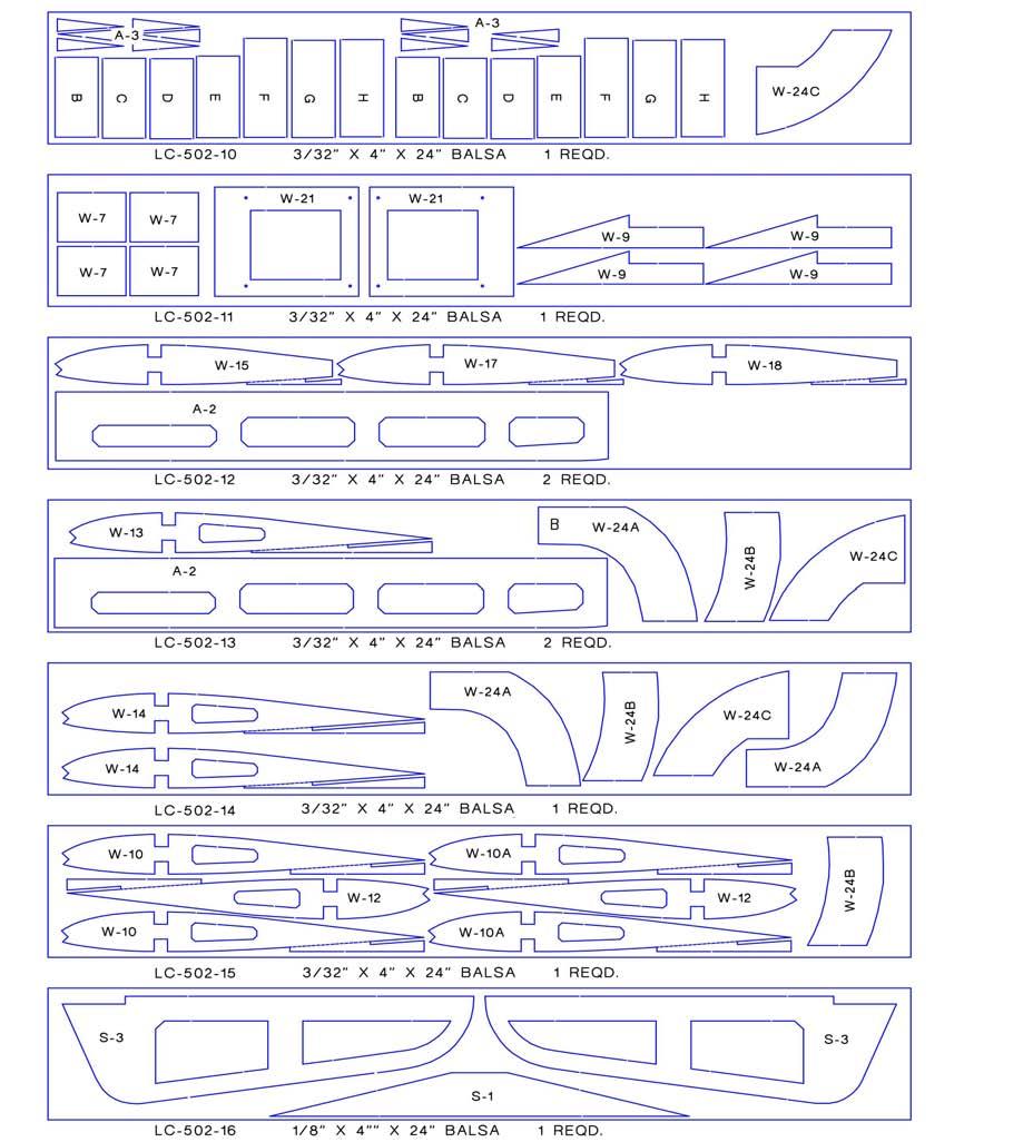
2 Notes about the laser cut parts 1...The first thing that you need to do is to identify and mark the part numbers on the laser cut parts using the drawings on the following pages as a guide. 2...It is possible that several of the laser cut parts may not be completely cut through. If this is the case you can free the part from the sheet quickly using an X-acto knife. 3...The slight discoloration on the edges of the laser cut parts may be removed by lightly sanding the edges with 400 grit sandpaper. Kit Contents: Your kit contains the following parts. Please check your kit for any missing or damaged parts before starting construction. Wood Bag: Qty......Name Description LC mm X 7-3/4 X 24 Laser Cut POPLAR PLY LC mm X 7-3/4 X 24 Laser Cut POPLAR PLY LC mm X 7-3/4 X 24 Laser Cut POPLAR PLY LC mm X 7-3/4 X 24 Laser Cut POPLAR PLY LC mm X 7-3/4 X 24 Laser Cut POPLAR PLY LC mm X 4 X 24 Laser Cut POPLAR PLY LC mm X 7-3/4 X 24 Laser Cut POPLAR PLY LC mm X 7-3/4 X 24 Laser Cut POPLAR PLY LC mm X 4 X 24 Laser Cut POPLAR PLY LC /32 X 4 X 24 Laser Cut BALSA LC /32 X 4 X 24 Laser Cut BALSA LC /32 X 4 X 24 Laser Cut BALSA LC /32 X 4 X 24 Laser Cut BALSA LC /32 X 4 X 24 Laser Cut BALSA LC /32 X 4 X 24 Laser Cut BALSA LC /8 X 4 X 24 Laser Cut BALSA LC /8 X 4 X 24 Laser Cut BALSA LC /8 X 4 X 24 Laser Cut BALSA LC /8 X 4 X 24 Laser Cut BALSA LC /16 X 4 X 24 Laser Cut Birch Ply LC /16 X 4 X 24 Laser Cut Birch Ply LC /32 X 1-1/2 X 12 Laser Cut Birch Ply Fuselage Sheet /8 x 4 x 24 Balsa Tail Sheet /16 x 4 x 24 Balsa Wing & Center Section Sheet /32 X 4 X 24 Balsa Wing Leading Edge Sheet /32 x 3 x 30 Balsa Wing Trailing Edge Sheet /32 x 1 1/2 x 18 Balsa Wing Trailing Edge Sheet /32 x 1 x 18 Balsa Plans Bag: K-502 PLAN A K-502 PLAN B K-502 PLAN C Fuselage Side & Nose Stringers /8 sq. X 36 Balsa Outboard Main Wing Spars /8 x 3/8 x 30 Bass Wing Leading Edge /8 x 3/8 x 30 Balsa Fuselage Braces /4 Triangle 12 Balsa Former Braces & Nose Stringers /4 Sq. x 12 Balsa (or 4 pieces 24 ) Front Wing Strut /16 x 1/2 x 36 Bass Rear Wing Strut /16 x 3/8 x 36 Bass Page 2
3 Hardware Bag Qty......Name Description Tailwheel Bracket Molded Nylon Bracket Landing Gear & Strut Straps Molded Nylon Straps Motor Mount Blind Nuts Blind Nuts Elevator Joiner Dowel /4 x 4 1/2 Birch Dowel Wing Dowels /4 x 1 Birch Dowel Wing Bolts /4-20 x 1 Nylon Screw Control Horn Aileron and Tail Control Horns /2 Sheet Metal Screws # 2 X 1/2 Sheet Metal Screw Tail Control Horn Screws x 1/2 Machine Screw Cowl & Strut Blocks /8 x 3/8 x 3/8 Hardwood Aileron Servo Mounts /8 x 3/8 x 1 Bass Wing Joint Tape x 40 Dacron Tape Strut End Tape x 12 Dacron Tape Tail Brace Wires /16 x 36 Nylon Line Tail Wheel Wire /16 x 6 Music Wire Center Main Wing Spars /8 x 3/8 x 7 Bass Misc. Loose Parts Main Landing /23 x Music Wire Windshield Plastic x 6 x 12 Clear Plastic Window Plastic x 4 x 6 Clear Plastic K-502 Decal K-502 Cowl Additional Items Required for Glow and Electric Power (Not Included in Kit) Covering Material Rolls Covering Material Plus Trim Colors Cowl Paint Can of Fuel Proof Paint to Match Covering Hinges C/A or Pin Style Hinges Tail Pushrods Dubro 30 Laser Rods (1 pair) ( Alien Aircraft P/N: AH-013) Aileron Pushrods Aileron 2-56 Pushrods (1 pair) ( Alien Aircraft P/N: AH-014) Main L/G Collars /32 Wheel Collars ( DuBro P/N: 140) Tail L/G Collars /16 Wheel Collars ( DuBro P/N: 137) Main Wheels /2 Wheels ( DuBro P/N: 350T) Tail Wheel Wheel ( DuBro P/N: 100TW) Radio Channel Radio with Receiver Tail Servos HiTec HS-311 Standard Servos or Equivalent Aileron Servos HiTec HS-81 Micro Servos or Equivalent Aileron Servo Extensions Servo Extensions to fit your radio Aileron Y Connector Y Connector to fit your radio Aileron Servo Extension Servo Extensions to fit your radio Additional Items Required for Glow Power Only (Not Included in Kit) Qty....Name Description Motor stroke stroke Motor Mount Dave Brown Motor Mount (to fit your motor) Motor Mount Screws x 3/4 Machine Screws (or size to fit your motor) Motor Screws x 1 Machine Screws (or size to fit your motor) Propeller x 6 Propeller (or size to fit your motor) Fuel Tank SS8 Slant Style Fuel Tank (Sullivan # 439) Throttle Pushrod Flexible Cable Pushrod (Sig SIGSH559) Fuel Line Medium Fuel Line (DuBro #222) Foam Rubber /4 Foam Rubber (DuBro # 513) Optional Spinner DuBro 2 1/4 Spinner (DuBro # 272) Throttle Servo HiTec HS-311 Standard Servo or Equivalent Throttle cable to servo dubro EZ Connector (DuBro #121) Page 3
4 Additional Items Required for Electric Power Only (Not Included in Kit) Qty....Name Description Motor Himax HC Brushless Motor ( Alien Aircraft P/N: AE-040) Speed Control Castle Creation Phoenix ICE 50 Electronic Speed Control ( Alien Aircraft P/N: AE-041) Battery Connector Male Deans Ultra Style connector ( Alien Aircraft P/N: AE-027) Arming Switch Arming Switch with 12 awg & Dean's Ultra Style Connectors ( Alien Aircraft P/N: AE-048) Motor Mounting Screws x 1 Socket Head Cap Screws ( Alien Aircraft P/N: AE-050) Battery Cell 5000Mah Lipo Battery 30C Heat Shrink Tube /16 Heat Shrink Tube ( Alien Aircraft P/N: AE-029) Propeller APC 12 x 6E Propeller ( Alien Aircraft P/N: AE-051) Velcro " Velcro ( Alien Aircraft P/N: AE-012) WARNING...EXTREME DANGER: Electric motors, propellers and batteries powerful enough to fly this model are extremely dangerous. These motors, propellers and batteries can cause serious property damage, serious bodily injury and death. Maximum safety precautions must be observed at all times when installing, maintaining and operating these items. Maximum safety precautions must be observed at all times when assembling, maintaining and operating this model. You must understand and follow all of the manufactures operating and safety instructions for every piece of equipment and component used with this model. YOU MUST USE AN ARMING SWITCH BETWEEN THE BATTERY AND SPEED CONTROLLER. If you have any doubt about the proper safety precautions, you must contact the manufactures to obtain the operating and safety instructions for every piece of equipment and component used with this model. You must read and follow the important notes on the cover and on page 54 of this manual. Page 4
5 Page 5
6 Page 6 F-13
7 Page 7

8 F-9C F-9B Page 8

 using the 1/4 x 4-1/2 dowel. Use the stabilizer as a guide to establish the proper spacing. Trim the dowel to achieve the proper length. 5.")
9 Building Instructions: General Note: Cover the plans with wax paper before assembling your model to prevent the parts from sticking to the plan. Building the Tail Surfaces: 1... Glue S-1 and S-2 together as shown. 2...Glue together two pieces of 1/16 x 4 x 24 balsa sheet as shown to make the stabilizer skin. 3...Glue this sheet to one side of the stabilizer. Trim the sheet flush with S-1 / S-2. Now sheet and trim the opposite side as you did the first. Be sure to cut out the rudder slot. 4...Use 1/16 balsa to sheet both sides of the elevators (S-3). Join the elevators (S-3) using the 1/4 x 4-1/2 dowel. Use the stabilizer as a guide to establish the proper spacing. Trim the dowel to achieve the proper length. 5...Bevel the front edge of the S-3 s as shown on the plan, and sand the other edges round. Sand the front and ends of the stabilizer round. Leave the back edge square. Mark the hinge locations and cut the hinge slots. Temporarily install the hinges without glue. Page 9


10 6...Glue R-1 and R-2 together. Glue R-3 and R-4 together. 7...Use 1/16 x 4 x 24 balsa to sheet both sides of R-1/R-2, and R- 3/R Bevel the front edge of R-3 as shown on the plan, and sand the other edges round. Mark the hinge locations and cut the hinge slots. Temporarily install the hinges without glue. Sand the outside edges round. Leave the other edges square. Building the Fuselage: 9...Assemble the RIGHT fuselage side using parts F-1R and F-2. Assemble the LEFT fuselage side using parts F- 1L and F-2. Be sure to make a right hand and a left hand side. L R 10...Glue the F-3, F-4R and F-5R doubelers to the inside of the RIGHT fuselage side. Glue the F-3, F-4L and F-5L doubelers to the inside of the LEFT fuselage side. Be sure to make a right hand and a left hand side. Use the drawing on the plan to properly locate the doublers on the fuselage sides. NOTE: The F-4 doublers go on the fuselage side. The F-5 doublers go on top of the F-4 s. Page Right Left 4 5


11 11...Glue F-14A and F-14B together Glue the two F-6 s together. Glue the two F-15 s together. Glue a 1/4 sq. balsa strip to the top of F-6 and F-15 as shown. When the glue is dry, sand the 1/4 balsa flush with the ends, front and back of the formers Glue 1/4 sq. balsa strips onto formers F-8, F-11 and F-12 as shown Glue F-24B and F-24C to F-24A as shown to make the fuel tank tray. The front of F-24A should angle back on the right side as shown Glue F-21A to the front of F-21B. Glue the two F-16 s together. F-21A on top Page 11


12 16...Glue the F-9 pieces together as shown. Glue two F-9A s together Glue F-9C at rear Glue two F-9E s at rear Bottom View This hole farther forward This hole farther back Glue F-9B at front Glue two F-9D s at front 17...Place formers F-6, F-7 and F-8 into position on the right fuselage side. They should be completely seated against the side and be 90 degrees to the fuselage side. When properly positioned, glue the formers securely to the fuselage side. The 1/4 braces on F-8 should be on the back side Position the left fuselage side into position on the formers. They should be completely seated against the side and be 90 degrees to the fuselage side. When properly positioned, glue the formers securely to the fuselage side. Page 12


13 19...Glue the F-9 assembly into position on the bottom of the fuselage as shown. The holes in F-9 should align with the slots in the fuselage doublers Cut a piece of 1/4 triangle to make a brace that fits across the bottom of F-6. This brace is on the backside of F-6 and down, tight against F-9. When properly positioned, glue the brace securely into place Cut two 1/4 triangles and glue onto the ends of F-9 and against the F-5 doublers as shown Place former F-10 into position and pull the rear of the fuselage sides together. Adjust the back end until the fuselage is straight and square. Glue the fuselage sides together and glue the former in place. Page 13


14 23...Place former F-11 into position and glue in place. The 1/4 balsa braces should be on the front side. Place former F-12 into position and glue in place. The 1/4 balsa braces should be on the front side Glue F-13 into position on the top rear of the fuselage. Spread and squeeze the sides as required to get F-13 to fit in the proper position Glue F-14 into position on the bottom rear of the fuselage. Spread and squeeze the sides as required to get F-14 to fit in the proper position Securely glue former F-15 into position on the top of the fuselage at the front of the wing saddle area. It should be glued to the fuselage sides and F Securely glue the F-16 assembly into place in the notches in the back of the F-3 doublers. Glue to the fuselage sides and F-8. Glue a 1/4 triangle between F-3 and F-16. When the glue is dry, trim the tops of the triangles to match the contour of the wing saddle. Page 14


15 28...Glue F-18 and F-19 together as shown Glue F-17 into position on the bottom of the fuselage as shown. Securely glue to F-9 and the fuselage sides Glue F-18 and F-19 into position on the bottom of the fuselage. Trim the front edge of F-18 if required to achieve the proper fit Moisten the outside of the forward fuselage sides with an ammonia based window cleaner such as Windex. Position former F-20 between the fuselage sides and squeeze the sides together to make tight contact and glue the former in place. Page 15


16 32...Carefully position the motor mount on the front of the firewall (F-21). Mark and drill the locations for the motor mount screws in the firewall Flip the firewall over and press the 6-32 blind nuts into place as shown. Secure the nuts with a small amount of thin C/A glue Moisten the outside of the forward fuselage sides with an ammonia based window cleaner such as Windex. Position the firewall between the fuselage sides and squeeze the sides together to make tight contact and glue the former in place Cut two 1/4 triangle braces to length and securely glue them into position against the back of the firewall and the fuselage sides. Page 16


 into position on the formers as shown.")
17 36...Glue former F-22 in position on the fuselage as shown Place former F-23 into position on the top of the fuselage, immediately in front of F-6. Angle the top of the former forward as shown on the plan. When the former is in the proper position, glue the former in place. Cut and glue three 1/4 sq. balsa strips into place in the notches in fuselage formers F-21B, F-20 and F-23. The back ends should be trimmed flush with the back of F Glue the fuel tank tray (F-24) into position on the formers as shown. The front edge should be tight against F Cut and glue The 1/8 sq. balsa strips into place in the notches in the bottom of the fuselage between formers F-21 and F-22. Page 17


18 40...Use a straight edge to draw on the fuselage side as shown. The line should match the angle of F-6 and be aligned with the back edge of F-6. See the detail on the plan for the proper position Cut a 6 x 4 piece from one of the 1/8 x 4 x 24 balsa sheets. Trim an angle on the back end to match the angle of F-6. Glue this piece on the fuselage side. The back edge should be on the marked line. The top edge should be flush with the fuselage side. When the glue is dry, trim the excess sheet flush with the bottom of the fuselage side, the front of F-22 and flush with the front of the firewall. Line 42...Use two pieces of 1/8 x 4 balsa to sheet the bottom of the fuselage as shown. The two pieces should meet on the center of the middle stringer. Trim the front flush with the front of the firewall. Trim the sides flush with the last 1/8 sq. stringer as shown. To make the wood bend easier, moisten the outside of the sheet with an ammonia based window cleaner such as Windex Use two pieces of 1/8 x 4 balsa to sheet the remaining corners on the bottom of the fuselage as shown. Trim the front flush with the front of the firewall. To make the wood bend easier, moisten the outside of the sheet with an ammonia based window cleaner such as Windex Use two pieces of 1/8 x 4 balsa to sheet the top of the fuselage as shown. Glue the bottom edge of the sheet to the fuselage side. Page 18


19 45...Moisten the outside of the sheet with an ammonia based window cleaner such as Windex. Roll the sheet around the formers and stringers. Each piece should end at the centerline of the middle 1/4 sq. stringer. Glue the sheet into place. When the glue is dry, trim the front flush with the firewall and trim the back flush with F Glue the F-25 window frames to the fuselage sides as shown Cut a piece of 1/8 balsa sheet to two strips 1/4 wide. Fit and glue these strips to the outside edge of former F-6 between the top of F-25 and the forward top nose sheet on each side of the fuselage as shown Glue the two F-26 window dividers into position as shown. The wider end is on the bottom. Page 19


20 49...Glue the 1/8 sq. balsa stringers to the fuselage sides. Use the drawing on the plan to determine the proper position Glue pieces of 1/8 sq. balsa to make the door framework and glue it to the fuselage sides as show. Sand the fuselage smooth all over. The wood in the door area should be tapered top to bottom as shown on the detail on the plan. DO NOT SAND the 1/4 balsa on top of formers F-6 and F-15. Building the Wing Center Section: 51...Glue the three W-6 s together. Glue the W-2A doublers to the front of the W-2 ribs. Be sure to make a left and right as shown Pin the lower 3/8 x 3/8 x 7 bass lower main spar to the plan. The ends will extend slightly past the W-2 ribs. Page 20


21 53...Glue the W-2 ribs into position on the lower main spar. The W-2A doublers should face inboard. The ribs should be 90 degrees to the building board. Glue the W-1 shear web into position on the rear of the spar between the W-2 ribs. It should be tight against the ribs and spar and aligned with the spar slot in the top of the rib Put the 3/8 x 3/8 x 7 bass top main spar into place. The ends will extend slightly past the W-2 ribs. Glue it to the ribs and shear web Glue the W-3 shear web into position on the front of the spar between the W-2 ribs. It should be tight against the ribs and spar Place the W-6 assembly into place between the W-2 ribs. It should be aligned up and down with the front corners of the W-2 ribs, and back against the W-2A doublers. When in the proper position, glue in place Cut one of the 3/32 x 1-1/2 x 18 balsa trailing edge sheets into two 9 pieces. Slide it into the slots in the rear of the W-2 ribs. Center it and make sure that it is fully seated in the slots and glue in place. Page 21


22 58...Slide the W-4 ribs into position. The top front edge should flush with the top edge of W-1. When in the proper position, glue the W-4 ribs to W-1 and the trailing edge sheet Glue the W-5 ribs into position between the W-6 assembly and W Glue the remaining 3/32 x 1-1/2 x 9 trailing edge sheet on top of the rear of the center section Glue two of the W-7 s together on top of each other. Glue the second set of W-7 s together. Use sandpaper to taper the two W-7 assemblies so they fit into the gap between the two trailing edge sheets. They should fit tight and be positioned as far back as possible. Glue the W-7 s in place Use the 3/32 x 4 x 24 balsa to sheet the top rear of the wing center section. The grain should run left to right. Leave the edges slightly long Page 22


23 63...Use the 3/32 x 4 x 24 balsa to sheet the remainder of the top of the wing center section. The grain should run left to right. Leave the edges slightly long 64...Remove the center section from the plan. Cut the support tabs from the bottom of the ribs Use the 3/32 x 4 x 24 balsa to sheet the bottom of the wing center section. The grain should run left to right. Leave the edges slightly long 66...When the glue is dry, trim the spars and sheet flush with the W-2 ribs and the front of W-6. Sand the top and bottom of the center section smooth. Page 23


24 67...Sand a bevel around the edges of W Glue W-8 on the top of the center section, centered left and right. It should be flush with the back of the trailing edge Test fit the wing center section onto the fuselage. Sand the back end if required to fit tightly down into the step in the fuselage. The front must be tight against and in full contact with F Center the center section left and right on the fuselage. Hold it tightly in position, and using a 3/16 drill bit, drill the bolt holes in parts F-16 in the fuselage. The drill bit must be centered in the 1/4 holes in the center section and be 90 degrees to the top surface of the center section so the bolt heads will sit flat. Page 24


25 71...Remove the wing from the fuselage. Using a 1/4 drill bit, drill out the wing bolt holes in the center section Use a 1/4-20 tap to cut threads in the holes drilled in F-16. Apply some thin C/A to harden these threads and when the glue is dry, re-tap to clean up the threads. Use the two 1 nylon bolts to attach the center section onto the fuselage Hold the center section tightly against the fuselage. Use a 1/4 drill bit to drill holes through F-6 into W-6 for the wing dowels. 90 Degrees to this line. WARNING!!! The dowel holes must be 90 degrees to F-15 and W-6. This means that you will be drilling through F-6 at an angle. Sight from the side to make sure that the drill is 90 degrees to F-15 and W-6 before you drill the holes Remove the center section from the fuselage. Insert the 1/4 dowels into the holes in W-6. They should stick out 3/8. Securely glue the dowels into position. When the glue is dry, check the fit on the fuselage again With the center section bolted to the fuselage, sand the 1/4 balsa on the top of formers F-6 and F-15 flush with the sheet on the top of the center section. Page 25


26 Building the Left Wing: 76...Cover the right wing plan with wax paper to prevent the parts from sticking to the plan Make one trailing edge by placing W-9 against one of the 3/32 x 1-1/2 x 18 balsa sheets. The end of W- 9 should be flush with the end of the 1-1/2 balsa. When properly positioned, glue the two pieces together Place one of the 3/32 x 1 x 18 balsa sheets against W-9. The end of the 1 balsa should be positioned as shown. When properly positioned, glue the two pieces together Trim the end of the 3/32 x 1 balsa sheet to match the angle on W-9 as shown. Now repeat the previous steps to make a second trailing edge Cut two 3/8 sq x 36 bass spars to 30. Pin the lower 3/8 x 3/8 x 30 lower main spar to the plan. The inboard end should be flush with the inboard face of the W-11 rib. Let the outboard end extend past the W-19 rib and the wing tip 81...Pin and glue rib W-10 into position on the bottom spar. It should be 90 degrees to the building board. Page 26


27 82...Glue shear web A into position against the front face of the lower spar and rib W-10 as shown on the plan. The small X on the shear web marks the top outboard corners of the shear webs Pin and glue rib W-11 into position. The top of the rib should angle slightly toward the wing tip and be in full contact with the shear web Pin and glue ribs W- 10A through W-19 into position on the spar. They should be 90 degrees to the building board Glue the 3/8 x 3/8 x 30 bass top spar into position. Page 27


28 86...Working from the tip to the center, slide the trailing edge under W-19 and then into the slots in the remaining ribs. Line up the aileron cutout with the outboard edge of W-14. Make sure that the trailing edge is fully forward in the slots and glue in place Glue the 3/8 sq. balsa leading edge into position. You can let the extra extend past the end ribs Glue two W-20 s together. Put into position and glue to the ribs and bottom trailing edge sheet between ribs W-14 and W Cut and glue three 1/4 sq. balsa fillers to the back of W-20 in the locations of the aileron hinges. Page 28


29 90...Glue the remaining shear webs B, C, D, E, F, G and H into position. Trim the ends to get the proper fit if needed Place the top trailing edge sheet into position and glue into place Position the 3/32 x 3 x 30 leading edge sheet against the leading edge as shown. When positioned properly, glue the sheet to the leading edge only Moisten the outside of the leading edge sheet with an ammonia based glass cleaner such as Windex. Allow it to soak in for several minutes. Roll the sheet back and glue thoroughly to the ribs and main spar Cut two pieces 8 long from one of the 3/32 x 4 x 24 balsa sheet. Save the 8 left over piece for use in the next step. Use the 8 pieces to sheet the inboard end of the wing from W-11 to just slightly past W-12, and between the leading edge sheet and trailing edge. Page 29


30 95...Cut 1/4 x 8 strips from the left over sheet from the previous step Use these 1/4 wide strips as cap strips and glue into position on top of the W-13 thru W-19 ribs. The cap strips should be centered on the ribs except for W-19. The W-19 cap strip should be flush with the outboard face of the rib and extend inboard Remove the wing from the plan. Trim the supports from the trailing edge of the wing ribs Using 3/32 x 3 x 30 balsa, sheet the lower leading edge as you did the top. Be sure that the wing is held straight so you do not induce a twist while applying this sheet Sheet the inboard end of the wing as you did the top Test fit W-21 on ribs W-14 and W-15 as shown. The wide edge on W-21 is the inboard end. Trim the back edge to fit tight against the trailing edge. When the proper fit has been achieved, glue W-21 into place. Page 30


31 101...Fit and glue 1/4 wide cap strips to the remaining ribs as you did the opposite side Trim the excess spars and sheet flush with the ribs on both ends of the wing Glue W-22 to W-23 to rib W-19 as shown. They should be centered top and bottom and positioned 90 degrees to the rib. Cut small 1/4 sq. balsa reinforcements and glue into position as shown. Note: The straight edge is on the top. The angle edge is on the bottom. bottom piece B Glue W-24A, W-24B and W-24C together to make the top wing tip. Glue W-24A(B), W-24B and W-24C together to make the bottom wing tip. top piece Page 31


32 105...Place the top wing tip piece into position. The rear edge should rest on top of, and be flush with the inboard edge of the rib. The front should overlap the leading edge sheet by about 1/8. The middle should rest on the W-22 and W-23 supports. When in the proper position, glue the wing tip to the back of the rib and to W-22 and W-23. DO NOT GLUE TO THE LEADING EDGE AT THIS TIME Press the front of the wing tip down and mark where it overlaps the leading edge sheet. Carefully trim away the leading edge sheet in this area so that the wing tip sits down flush with the leading edge sheet Press the front of the wing tip into position and glue in place. Page 32


33 108...Position and glue the bottom wing tip piece in place Glue the outside of the wing tip pieces together as shown Glue three W-25 s to the front of the wing tip as shown Sand the leading edge of the wing round to match the profile shown on the plan. Sand the trailing edge and the edges of the wing tip round. Leave the edges of the aileron cutout square. Now sand the wing smooth all over. Page 33


34 112...Drill a 3/64 hole through four 3/8 x 3/8 x 3/8 bass cubes as shown Mark the wing strut locations on the bottom of the wing at rib W-16. Measure from the plan to get the proper locations Trim away the inboard edge of the cap strip from the bottom of the wing and position the rear strut block flush with the bottom of the wing. When the block is in the proper position, glue it in place Mark the location of the front strut block in the bottom of the wing. The outboard edge of the block should be against rib W-16. Page 34


35 116...Cut away the bottom sheet and glue the block into position, flush with the bottom of the wing Cut a brace from one of the 3/16 x 1/2 x 36 bass struts and glue into position as shown. It should be up against the inside of the cap strip and tight against the ribs and the rear strut block. Repeat steps 76 thru 117 to build the right wing. Building the ailerons: Build the right aileron Glue two A-1 s together. Trim an slight angle on the bottom edge of the A-1 s Glue the A-1 onto and flush with the front of A-2. Place it with the angle down so it leans slightly toward the trailing edge. Page 35


36 120...Glue the first A-3 rib into position. It should be flush with the end and 90 degrees to A Position two A-4 s into position against A-1 and A-3 and glue into place Glue the remaining A-3 s into place. Cut and glue three 1/4 sq. balsa fillers to the back of A-1 in the locations of the aileron hinges. These fillers are shown on the plan but not in the photo Trim an angle on the top of the A-1 s to match the angle on the top of the A-3 s Glue A-2 onto the top of the aileron. Sand the ends, front, top and rear of the aileron flush. Page 36


37 125...Draw a line centered on the front of the aileron. Draw a line 1/8 back from the leading edge on the top and bottom of the aileron Use these lines as a guide to trim or sand the proper angles on the front of the aileron as shown on the plan Glue the four W-26 s in position on the inside of W-21. Line up the holes in the W-26 s with the holes in W-21 and glue in place Mark a line centered on the back of the aileron spar (W-20). Mark the hinge locations and cut slots for the hinges. Temporarily install the hinges and check the aileron for proper fit on the wing. Do not glue the hinges at this time Repeat steps 118 thru 128 to build the left aileron. Joining The Wing: Glue six of the 1/16 plywood wing joiner pieces to make one joiner. Glue the remaining six 1/16 plywood wing joiner pieces to make the other joiner. Page 37


38 130...Glue W-28 to the bottom of the center section in the position shown on the plan. Cut out the opening in the bottom sheet for the aileron servo wires as shown Cut open the 3/8 wide slots in the W-2 ribs between the dashed lines for the wing joiners Mark the two wing joiners as shown on the plan Test fit the joiners into the slots in the W-2 ribs. The outboard ends of the joiners should angle up. The top outboard corner of the joiners is cut off at a 45 degree angle. Securely glue the joiners in place Cut slots in both W-11 ribs at the dashed lines to accept the wing joiner Slide the wing joiner on the center section into position in the right wing. Glue the right wing to the center section. Glue the joiner to the shear web and the top and bottom spars and glue the rib to the center section Slide the wing joiner on the center section into position in the left wing. Position it tightly between the spars and forward against the shear web and glue the left wing to the center section Sand the joint between the wings and the center section. Test fit the wing onto the fuselage and sand the wing as required to produce a good fit if needed. Page 38


39 138...Cut the 2 dacron tape into four 10 pieces. Glue the tape on the top of the wing. Start at back end. Tack the end down, centered on the joint. Now pull the tape tight and tack at the front Now use thin C/A glue to attach the tape to the wing. Use adequate ventilation. When the glue is dry, trim the tape at the front of W-6. Repeat the previous steps to apply the tape to the bottom wing joints. Page 39


40 Now sand the wing smooth all over. Building the wing struts: Cut an angle on one end of one of the 3/16 x 1/2 x 36 bass front struts. Use the detail on the plan as a guide Place one of the nylon fittings on the strut with the center of the fitting flush with the edge of the strut. Mark the fitting location on the strut Cut a pocket for the fitting to fit into. The fitting should be recessed deep enough so the top of the fitting is flush with the strut Bend an angle in the middle of the fitting as shown. Page 40


41 143...Sand the strut edges round. Use thick C/A glue to attach the fitting to the end of the strut. Use enough glue to cover the top of the fitting and fill the hole Wrap the end of the strut with a piece of the 1 nylon tape and secure with thin C/A. When the glue is dry, sand the tape smooth Check the wing for warps. Make sure that it is straight and true. Attach the wing on the fuselage. NOTE: If there are any twists in the wings, remove them now. You may also wait to make the struts after the model is covered. The covering may be used to remove any twists in the wing. The wing MUST be absolutely straight before making the struts Temporarily mount the landing gear wires to the fuselage. Temporarily attach parts LG in position and hold with masking tape. Screw the wing strut fitting to the front strut block on the wing. Hold the strut against the fuselage just behind the landing gear fairing. Mark the strut as shown. Page 41


42 147...Cut the strut to length. Install a fitting to this end of the strut. Do not wrap with nylon tape at this time. Drill a hole through the fitting into the fuselage and screw the lower end of the strut to the fuselage Attach a fitting to one end of one of the 3/16 x 3/8 x 36 bass rear strut as you did the front. Attach the rear strut to the wing. Place the rear strut on the lower strut at the fuselage as shown Mark the rear strut as shown. Now curt the rear strut on the marked line Make sure that there are no warps or twists in the wing or that there is any pressure on the wing that might twist it. Glue the rear strut to the front strut. When the glue is dry, wrap the lower end of the struts with the nylon tape as you did the top. Now make and install the strut to the opposite side of the model. Page 42


43 151...Glue 3/8 bass blocks inside the fuselage centered on the strut screw hole as shown. Remove the struts and wing from the fuselage Glue the four 3/8 Bass blocks to the front of the firewall at the locations shown on the plan. When the glue is dry, sand the outside of the blocks flush and to match the angle of the fuselage sides Temporarily mount the the motor mount to the firewall Temporarily mount the the motor on the mount Temporarily mount the muffler on the motor to make sure it fits and the exhaust clears the firewall. Page 43


44 156...Cut on the dashed lines to remove the wood from the stabilizer slots on the fuselage sides. Temporarily mount the tailwheel bracket to the bottom of the fuselage. It should be positioned so that the 1/16 axle is just at the back of the fuselage as shown on the plan Test fit the tail surfaces on the fuselage. Sand or trim if required to obtain the proper fit. Covering: Sand all parts smooth with 400 grit sandpaper. Feed strings from the aileron servo mounts to the center section. You will use these strings to pull the servo wires thru the wing after the model is covered. Cover the model with a plastic iron on covering material. Overlap all seams approximately 1/8. Note: After the model is covered you must check the tail surfaces and wings for warps or twists. If there are any they can be removed by twisting the parts straight and heating the covering. Final Assembly: Glue the 3/8 sq. x 1 bass servo mounts to the W-27 mount plates. Mount the servos into position on the mounts. The servo arms should be angled 30 degrees forward to the plate when the servo is in neutral. Be sure to make a left and a right hand assembly. Page 44


45 160...Attach the ailerons to the wing with the hinges and glue in place. Cut the covering away from the aileron servo openings Screw the servo mount plates to the wing. The servo arms should be forward and inboard as shown. Use the strings in the wing to feed the servo wires through the wing and out the center section Screw the aileron control horns to the bottom of the ailerons in the position shown on the plan. Use #2 sheet metal screws. Use epoxy on the screws to secure them in place Assemble the aileron pushrods as shown on the plan. Install the pushrods making sure the ailerons are in neutral when the servos are in neutral. Page 45


46 164...Cut the covering away from the stabilizer, fin and pushrod slots in the fuselage Cut the covering away from the stabilizer in the area that makes contact with the fuselage. Place the stabilizer into position in the fuselage. Make sure that it is straight and square and then glue it into position Carefully cut the covering away from areas on the fin that will make contact with the fuselage. Carefully cut the covering away from areas on the fuselage that will make contact with the fin. Place the fin into position and make sure that it is straight and square. Glue the fin into position Attach the elevators with the hinges and glue in place Attach the tail wheel bracket to the bottom of the fuselage. Glue the screws in place. Page 46


47 169...Make the bottom two bends in the tail wheel wire as shown. Use the drawing on the plan as a guide Install the wire into the bracket. Using the plans and the rudder as a guide, make the top bend in the music wire Drill a 1/16 hole in the front of the rudder for the tail wheel wire. Attach the rudder with the hinges and glue in place. Use epoxy on the tail wheel wire Attach the tail wheel with a 1/16 wheel collar Insert the pushrod housings into the exit slots in the back of the fuselage. They should stop 3 forward of the hinge lines. Glue the housings to the rear exits. Page 47


48 The front ends of the pushrod housings should pass thru the slot in former F-8. Do not glue the front ends to the former at this time Assemble the back end of the pushrods using short pieces of threaded rod and large clevises Attach the control horns to the elevator and rudder with 2-56 machine screws and back plates. Slide the pushrods into the housings and connect the clevises to the horns Screw the servos to the servo tray Assemble the front ends of the pushrods and connect them to the servo arms. The control surfaces should be in neutral when the servos are centered. Glue the pushrod housings to former F-8. Page 48


49 178...Fold the plastic tail brace in half and make a sharp bend in the middle Drill 1/16 holes in the fin and stabilizer in the locations shown on the plan. Feed the brace wire through the fin and center the bend on the fin Thread the brace wire through the holes in the stabilizer on each side. Mark the brace and make sharp bends where it passes through the stabilizer Drill a 1/16 hole in each side of the fuselage in the location shown in the photo. Insert the ends of the brace into the holes. Pull the wire tight and glue to the fuselage with thin C/A glue. NOTE: Make sure that the braces are tight with no slack. However, do not pull them so tight that they pull the tail surfaces out of position. Page 49


50 182...Seal the firewall with dope or epoxy. Attach the motor mount. Use a thread locker on the screws. Drill the firewall for the throttle cable and fuel and vent line. Glue the throttle housing into the firewall. Assemble the fuel tank. Wrap with 1/4 foam rubber and slide into the tank mount tray while pulling the fuel and vent line through the firewall Mount the motor and muffler. Attach the fuel line to the motor. Attach the vent line to the muffler. Make up the front end of the throttle cable and use a nylon clevis. Pass the throttle cable through the housing and attach the clevis to the throttle arm Mount the throttle servo to the tray. Attach the throttle cable to the servo with an EZ Connector. Secure the back end of the housing to the fuselage side using a scrap piece of wood as needed for alignment. Page 50


51 185...Cut the windshield to the pattern on the plan. Tape it down at the top of F-15 / F-6. Wrap it around and tape the lower rear corners to the fuselage sides. Mark and trim as required Mark where the windshield makes contact with the top of the nose of the fuselage. Cut away the covering from this ares. Finish the bare wood as desired Now glue the top of the windshield to the top of the formers. Start at the top. When this is dry work your way slowly around the rest of the windshield. NOTE: By sanding the covering material lightly with 400 grit sandpaper you can use thin C/A glue to attach the windows to the covering material and achieve a good bond. You may also cut the covering material away and glue the windows to the wood. Warning...If you use C/A glue for the windshield, care must be used sparingly to prevent fogging of the plastic. Warning...Do Not use accelerator as it will cause the plastic to craze Cut the side windows from the plastic sheet. They should be about 1/16 oversize. Glue them into position on the outside of the model Attach the main landing gear wire to the fuselage with the nylon straps and #2 sheet metal screws. Apply epoxy on the vertical legs and into the holes in the fuselage during assembly. Angle the straps so that the screws are against the landing gear wires. Page 51


52 190...Attach the parts LG to the fuselage with #2 sheet metal screws and plastic brackets. Pre-bend the brackets as you did for the wing struts. Bond parts LG to the landing gear wires with silicone rubber. The fairings should be on top of the wires and flush with the front of the wires. Scuff up the covering material and wire with 220 grit sand paper to assure proper adhesion. Trim the screws with the outer surface of the LG s. Secure the screws with C/A glue Put the wheels on the model and secure with 5/32 wheel collars on each side of the wheels Draw a line on the cowl approximately 5-1/2 back from the front of the cowl as shown. Measure your engine installation. The cowl should be long enough to overlap the front of the fuselage at least 1/2. Adjust the location of this line accordingly to fit your engine. The base of the cowl as formed is at an angle and all measurements should be made from the front. Tape a marker on a block of wood or other spacer that gives the required distance. Hold the front of the cowl tightly on a flat surface and gently go around it to mark the trim line. Note: It is always better to leave the cowl a little long. The final trim of the back edge can be accomplished after the cowl is fitted to the fuselage Trim the back of the cowl on the line marked in the previous step. Cut the pattern from the plan and use it to mark the locations of the openings on the front of the cowl. Trim the openings in the front of the cowl. Trim the opening for the exhaust as required. Page 52


53 194...Drill a 1/16 hole in the center of each cowl block. Tape paper strips to each side of the fuselage. These strips should extend forward over the cowl blocks. Mark the cowl block hole position on the paper strips Slide the cowl into position. Center the prop shaft in the hole in the cowl and slide the cowl back to provide the proper propeller and spinner clearance. Squeeze the sides of the cowl into contact with the mounting blocks. Be sure to keep the propeller shaft centered in the cowl. Drill holes in the cowl using the paper strips as a guide. Install the screws in the sides of the cowl Locate and cut the holes in the cowl for the needle valve, cylinder head and carburetor access. Remove and paint the cowl with a fuel proof paint as required. Then mount back on the model Wrap the receiver and battery pack with foam rubber. You will probably need some nose weight in the model so place the battery as far forward, under the fuel tank, as possible. Secure the receiver and run the antenna in accordance with the radio s instructions Check the servos for proper operation and direction. Adjust the control throws to the values shown on the plan. Attach the propeller. Attach the wing onto the fuselage Check the balance of the model. It should balance at the position shown on the plan. Move the battery forward or aft to achieve the proper balance. Note: If moving the battery will not achieve the proper balance (it probably won t), you will have to add weight to the nose or tail. Glue or bolt any weight securely to the model Your model is now ready to fly. Fully charge the transmitter and airborne battery before attempting to fly the model. Always range check and do a thorough pre-flight of the model before every flight. Always follow established safety guidelines while operating the motor, radio and flying your model. Page 53
54 NOTES ABOUT THE ARMING SWITCH: *For electric powered models... *YOU MUST USE THE ARMING SWITCH. THIS IS AN IMPORTANT SAFETY ITEM. *THE PLUG SHOULD ONLY BE INSERTED IN THE ARMING SWITCH IMMEDIATELY PRIOR TO FLIGHT. *ALWAYS REMOVE THE PLUG FROM THE ARMING SWITCH IMMEDIATELY AFTER EVERY FLIGHT. *THE PLUG SHOULD NEVER BE INSERTED IN THE ARMING SWITCH WHILE CHANGING OR INSTALLING THE BAT- TERY IN THE MODEL. *BE ABSOLUTELY SURE THAT THERE ARE NO OBJECTS, CLOTHING, BODY PARTS, ETC. ANYWHERE NEAR THE PROPELLER AND THAT THE MODEL IS SECURELY RESTRAINED BEFORE INSTALLING THE PLUG IN THE ARMING SWITCH. LIPO BATTERY SAFETY ALERT Lithium Battery Fires Lithium batteries are becoming very popular for powering the control and power systems in our models. This is true because of their very high energy density (amp-hrs/wt. ratio) compared to NiCd s or other batteries. With high energy comes increased risk in their use. The principal risk is FIRE which can result from improper charging, crash damage, or shorting the batteries. All vendors of these batteries warn their customers of this danger and recommend extreme caution in their use. In spite of this, many fires have occurred as a result of the use of Lithium Polymer batteries resulting in loss of models, automobiles, and other property. Homes and garages and workshops have also burned. A lithium battery fire is very hot (several thousand degrees) and is an excellent initiator for ancillary (resulting) fires. Fire occurs due to contact between Lithium and oxygen in the air. It does not need any other source of ignition, or fuel to start, and burns almost explosively. These batteries must be used in a manner that precludes ancillary fire. The following is recommended: 1. Store, and charge, in a fireproof container; never in your model. 2. Charge in a protected area devoid of combustibles. Always stand watch over the charging process. Never leave the charging process unattended 3. In the event of damage from crashes, etc, carefully remove to a safe place for at least a half hour to observe. Physically damaged cells could erupt into flame and after sufficient time to ensure safety, should be discarded in accordance with the instructions which came with the batteries. Never attempt to charge a cell with physical damage, regardless of how slight. 4. Always use chargers designed for the specific purpose, preferably having a fixed setting for your particular pack. Many fires occur in using selectable/adjustable chargers improperly set. Never attempt to charge Lithium cells with a charger which is not specifically designed for charging Lithium cells. Never use chargers designed for Nickel Cadmium batteries. 5. Only use charging systems that monitor and control the charge state of each cell in the pack. Unbalanced cells can lead to disaster if it permits overcharge of a single cell in the pack. If the batteries show any sign of swelling, discontinue charging and remove them to a safe place outside as they could erupt into flames. 6. Most important: NEVER PLUG IN A BATTERY AND LEAVE IT TO CHARGE UNATTENDED OVERNIGHT. Serious fires have resulted from this practice. 7. Do not attempt to make your own battery packs from individual cells. These batteries CANNOT be handled and charged casually such as has been the practice for years with other types of batteries. The consequence of this practice can be very serious resulting in major property damage and/or personal harm. Page 54
Stearman PT-17 KIT WARRANTY
 Stearman PT-17 KIT # K-306 Assembly Instructions Version 2 02-17-16 Designed by Tom Herr WARRANTY Sig Manufacturing Co, Inc. guarantees this kit to be free from defects in both material and workmanship
FUSELAGE CONSTRUCTION
 FUSELAGE CONSTRUCTION Note: prior to building and gluing on the work surface use protective covering on your building surface. (wax paper or clear wrap) Fit the laser cut Fuselage Front and Fuselage Rear
Sig Mfg. Co., Inc South Front Street...Montezuma, Iowa 50171
 Sig Mfg. Co., Inc...401-7 South Front Street...Montezuma, Iowa 50171 Introduction The SEALANE takes off and lands on water just as easy as the Sig Kadet LT40 does on solid ground. Gentle, graceful, sure
Citabria Pro. Aerobatic Parkflyer. by Joel Dirnberger
 Citabria Pro Aerobatic Parkflyer by Joel Dirnberger Revision C: December 21, 2004 Citabria Pro Building Instructions Length: Wingspan: Wing Area: Flying Weight: Wing Loading: Functions: Specifications:
LANDING GEAR. 1. Fit landing gear into slots on bottom of fuselage.
 LANDING GEAR 1. Fit landing gear into slots on bottom of fuselage. 4. Use channel-lock pliers to press blind nuts into position (note: drilled hole should be slightly smaller than shaft of blind nut for
C-180 Builder s Manual
 C-180 Builder s Manual. May 20, 2002 Last revised July 11, 2002 Copyright! 2002 Douglas Binder, Mountain Models www.mountainmodels.com sales@mountainmodels.com (719) 630-3186 1 Required Equipment! Xacto
Taylorcraft Indoor / Cul-De-Sac Flyer
 Taylorcraft Indoor / Cul-De-Sac Flyer Taylocraft Specifications Wingspan: 28.0 in. Wing Area: 117 sq. in. Weight (Ready to Fly): 3.0 3.1 oz. Wing Loading: 3.7 3.8 oz. / sq. ft. LIABILITY RELEASE In that
Your kit contains the following parts. Please check your kit for any missing or damaged parts before starting construction.
 Your kit contains the following parts Please check your kit for any missing or damaged parts before starting construction COMPLETE KIT PARTS LIST 1 Plan Sheet #1 1 Plan Sheet #2 2 Decal Sheet 2 White Tissue
(Build Instructions)
") (Build Instructions) Specifications * Wingspan: 58cm * Length: 50cm * Flying Weight: 59 grams * Channels: 3 (Rudder Elevator Throttle) * Suggested Receiver: 4Ch Micro * Motor: 8mm GearDrive * Prop: GWS
(Build Instructions) Specifications * Wingspan: 58cm * Length: 50cm * Flying Weight: 59 grams * Channels: 3 (Rudder Elevator Throttle) * Suggested Receiver: 4Ch Micro * Motor: 8mm GearDrive * Prop: GWS
Instruction Manual. Specification:
 Instruction Manual H I G Specification: Wingspan: 133 cm (52.3 inches) Length : 104 cm (40.9 inches) Weight : 1830gr Engine : 25-32 two stroke Radio : 4 channel - 4 servo H W I N G KIT CONTENTS: We have
MECOA EZ-4061 Trainer
 MECOA EZ-4061 Trainer EZ-4061 is a newly designed, Almost Ready to Fly kit. It is an extremely easy to control trainer with strong construction and excellent aerodynamic performance. This is a great choice
SPUNKY ASSEMBLY MANUAL
 SPUNKY ASSEMBLY MANUAL Please read the tips section at the back of this manual regarding the use of laser cut parts. The proper removal and preparation of these parts is important. When laser cut, some
ParkJet Builder s Manual
 ParkJet Builder s Manual Thank you for purchasing the ParkJet. The ParkJet is a profile ducted fan airplane that can be flown in a larger park. The ParkJet was initially designed by Scott Stoops and modified
Parts Identification
 We are excited to introduce the Model Aero Aqua Sport. This is an excellent sport flyer, equally at home flying from grass fields, water, or even snow! The unique V-tail gives the Aqua Sport a distinctive
Instruction Manual book
 Instruction Manual book ITEM CODE BH53. SPECIFICATION Wingspan : 1,250mm 49.21 in. Length : 930mm 36.61in. Weight : 1.1kg 2.42 Lbs. Parts listing required (not included). Battery: 3 CELLS-LI-POLY-11.1V-2,500
Dandy Sport Builder s Manual
 Dandy Sport Builder s Manual Thank you for purchasing the Dandy Sport. The Dandy Sport has been designed as an easy to build aileron trainer. Take your time and enjoy building this plane. Specifications:
SwitchBack Senior. SwitchBack Senior Specifications
 SwitchBack Senior SwitchBack Senior Specifications Wingspan: 55.4 in. Length: 41 in. Wing Area: 597 sq. in. Weight (Ready to Fly): 34 to 37 oz. Wing Loading: 8.2 to 8.9 oz. / sq. ft. Version 1.05, March
ULS Cherokee. Ultra Low Speed aircraft for indoor RC flying. Zippkits. Specifications: Required to complete:
 Zippkits ULS Cherokee Ultra Low Speed aircraft for indoor RC flying. Specifications: Span- 28 inches Wing Area- 151 Sq/In Wing Loading- 3.0 ounces/ft Weight- 3.5 ounces RTF Build time- 1-2 Hours Radio-
LANIER - Double Trouble - INSTRUCTIONS. Tail 1 T1 ¼ Balsa 1 T2 ¼ Balsa 2 T3 ¼ Balsa 1 T4 ¼ Balsa 1 T5 ¼ Balsa 1 T6 ¼ Balsa 2 J1 ¼ Balsa 2 J2 Lite ply
 Tail 1 T1 ¼ Balsa 1 T2 ¼ Balsa 2 T3 ¼ Balsa 1 T4 ¼ Balsa 1 T5 ¼ Balsa 1 T6 ¼ Balsa 2 J1 ¼ Balsa 2 J2 Lite ply Other Parts 2 Aluminum Gear 1 3/32 Music wire tail skid 2 Elevator and J-plane joiner wire
Piper Cherokee /3 scale. Construction Manual
 Piper Cherokee 140 1/3 scale Construction Manual STAB CONSTRUCTION 1. Remove foam cores from cradle and place on flat surface. Inspect pieces before you epoxy halves together making sure leading and trailing
HIGH-END TECHNOLOGY. Electric ducted fan Starfighter
 HIGH-END TECHNOLOGY RC Electric ducted fan Starfighter First we want to thank and congratulate you with your decision in buying one of our Kits. The Starfighter puts together very easily so there is not
LANIER - Ultimate Pitts - INSTRUCTIONS. Additional Parts Required. (12) 4-40 blind nuts (Dubro #606)
 4-40 blind nuts (Dubro #606)") Additional Parts Required (4) or more channel radio with 7-8 servos..91-2.2 two stroke or 1.20-1.84 four stroke engine Appropriate Master Airscrew prop and Hayes mount for your engine. 3 Tru-Turn spinner
Additional Parts Required (4) or more channel radio with 7-8 servos..91-2.2 two stroke or 1.20-1.84 four stroke engine Appropriate Master Airscrew prop and Hayes mount for your engine. 3 Tru-Turn spinner
FLITZEBOGEN-2 Assembly instructions
 FLITZEBOGEN-2 Assembly instructions Trim the end of the fuselage to the length of 925mm from the nose. Be careful to avoid splitting the carbon fibers. Sand the base of the stab mount in preparation for
PITTS S2S CONSTRUCTION
 PITTS S2S CONSTRUCTION FUSELAGE CONSTRUCTION 1) Place the right fuselage side over the plan and mark the former positions. Place the left side over the right side and mark the former positions. Glue F1
JAMISON SPECIAL. Building Guide
 JAMISON SPECIAL Building Guide WING Mark then drill holes for wing jig rods. Slide Ribs onto jig rods Mark the rib positions on 1/16 x 1 trailing edge, 1/4 x 1/4 leading edge & 1/4 x 1/4 spars Pin ribs
BUILDING THE A6M2 ZERO
 BUILDING THE A6M2 ZERO Product Support (Do Not Remove From Department) TOP FLITE MODELS, INC CONGRATULATIONS' You now own the most accurate R/C Stand-Off Scale kit ever produced We at Top Flite hope that
LoLo. A sporty parkflyer with an Old Timer flair! Designed by: Tres Wright Kitted by: Park Scale Models
 LoLo A sporty parkflyer with an Old Timer flair! Designed by: Tres Wright Kitted by: Park Scale Models http://www.parkscalemodels.com/ Assembly Instructions General Information The laser cutting process
RESolution V2 Manual
 RESolution V2 Manual Note for the German Manual: Yellow Bottle thick CA Pink Bottle Med CA Blue tube 5 minute Epoxy Green tube 90 Minute Epoxy Construction of the Fuselage Step 1: Cover the plan with a
LANIER Dominator INSTRUCTIONS
 ADDITIONAL EQUIPMENT NEEDED TO COMPLETE YOUR DOMINATOR 500 General 3.2 to 4.2 Size two stroke R/C engine, muffler, and engine mount Gas or glow fuel line Minimum of 4 channel radio set required (4-5) 70
TWEETY 25 INSTRUCTION MANUAL. Almost Ready to Fly Nitro/Electric Aerobat FEATURES SPECIFICATIONS
 TWEETY 25 Almost Ready to Fly Nitro/Electric Aerobat INSTRUCTION MANUAL SPECIFICATIONS FEATURES WINGSPAN: 45.7 (1160mm) LENGTH: 38.6 (980mm) WING AREA: 370 sq in(24 sq dm) FLYING WEIGHT: Approx. 3.3 lbs
Thank you for your purchase of the Lee Ulinger, FoamtanaS, Yak-55, or Extra 330 3D Depron foam, Aerobatic airplane.
 Thank you for your purchase of the Lee Ulinger, FoamtanaS, Yak-55, or Extra 330 3D Depron foam, Aerobatic airplane. Tools you will need to build Recommended additional items: #11 hobby knife Motor: Hacker
SZD-10 bis CZAPLA ASSEMBLY MANUAL IN PICTURES
 1 RUDDER Plan and parts: 2 Assembly steps: Photo above: glue together rudder spar, ribs and trailing edge. Clamp spar to a flat surface (chipboard on the photo) and make sure the straight aligment of the
90 WING SPAN P-51D MUSTANG (COPYRIGHT PROTECTED 2014) ALL RIGHTS RESERVED
 ALL RIGHTS RESERVED") 90 WING SPAN P-51D MUSTANG (COPYRIGHT PROTECTED 2014) ALL RIGHTS RESERVED GENERAL INSTRUCTIONS This design is basically an enlargement of the very popular fun scale Mustang 60 Size. You can build it light
90 WING SPAN P-51D MUSTANG (COPYRIGHT PROTECTED 2014) ALL RIGHTS RESERVED GENERAL INSTRUCTIONS This design is basically an enlargement of the very popular fun scale Mustang 60 Size. You can build it light
RYAN STA SAFETY PRECAUTIONS. "Sport Scale E-Power ARF" For Intermediate and Advanced Fliers. This radio control model is not a toy!
 RYAN STA "Sport Scale E-Power ARF" For Intermediate and Advanced Fliers. SAFETY PRECAUTIONS This radio control model is not a toy! First-time builders should seek advice from people with model building
105" TIGER MOTH ARF INSTRUCTION MANUAL VERSION 1.0
 105" TIGER MOTH ARF INSTRUCTION MANUAL VERSION 1.0 Step 1. Installation of the aileron servos 1) Mount aileron servo to servo mounting blocks with servo s screws. Install servo mounting plate with screws.
Switchback Sport Builder s Manual
 Switchback Sport Builder s Manual Thank you for purchasing the Switchback Sport. The Switchback Sport has been designed for the novice to intermediate pilot who wants a plane with good performance that
INCLUDED IN THIS KIT: SPECIFICATION: NEEDED BUILDING TOOLS: REQUIRED EQUIPMENT:
 Please review this entire manual before beginning assembly. By doing so it will help you better understand each step as you progress in the actual building of your kit, and you will do a better job in
TIGER MOTH 120 ASSEMBLY INSTRUCTIONS
 TIGER MOTH 120 ASSEMBLY INSTRUCTIONS SPECIFICATIONS Wing Span: Length: Radio: Flying Weight: 1920mm 1580mm 4 channel with 6 servos 4200g AILERON ASSEMBLY 1 Start by removing the servo cover from the bottom
LARK. Classic Legal Precision Stunter RSM DISTRIBUTION. presents. Charles Mackey. Wing Area 570sq. Wingspan 52.
 RSM DISTRIBUTION presents LARK By Charles Mackey Photo _ Bob Hunt Classic Legal Precision Stunter Wingspan 52 Length 39.5 Wing Area 570sq Motor 35-46 www.rsmdistribution.com Page 2 Thank you for purchasing
Combat plane for Open B Lanier R/C Inc. P.O. Box 458 Oakwood, GA Phone Fax copyright 2003 Lanier R/C
 Combat plane for Open B Lanier R/C Inc. P.O. Box 458 Oakwood, GA. 30566 Phone 770 532 6401 Fax 770 532 2163 copyright 2003 Lanier R/C Important information: Please inspect the plane before beginning to
84 WING SPAN MESSERSCHMITT BF-109
 84 WING SPAN MESSERSCHMITT BF-109 (COPYRIGHT PROTECTED 2014) ALL RIGHTS RESERVED MEISTER 84 ME-109 SIERRA GEAR UPDATE PLEASE NOTE: THE MAIN GEAR MOUNTING PLATE FROM SIERRA IS NOT SQUARE. YOU HAVE TO ROUND
1/6 PA-25 PAWNEE. *Specifications are subject to change without notice.*
 1/6 PA-25 PAWNEE INSTRUCTION MANUAL [ A335 Kit ] Wing Span : 72 in / 1830 mm Wing Area : 736 sq in / 47.5 sq dm Flying Weight : 6.6 lbs / 3000 g Fuselage Length : 48 in / 1220 mm Requires : "Glow Power"
E-AERO EPP PITTS KIT From BP HOBBIES. Parts Included in kit
 E-AERO EPP PITTS KIT From BP HOBBIES Parts Included in kit Thank you for purchasing the BP Hobbies/E-aero EPP Pitts. Please take the time to read through the instruction manual before beginning the build.
Corvus Racer CC
 Corvus Racer 540 35CC Item No:L-G035008 Specifications Wing Span Length Wing Area Flying Weight Glow Gasoline Electric Radio mm mm 1200sq in (77.4sqdm) 9.9-12lbs(4.5-5.5kg) 91-1.20(2C) 1.10-1.40(4C) 20-40cc
MOUNTAIN MODELS P-51 Mustang. 1/12 Scale Electric Park Flyer. Copyright Mountain Models
 1 MOUNTAIN MODELS www.mountainmodels.com P-51 Mustang 1/12 Scale Electric Park Flyer Wingspan: 37, Wing Area: 254 sq. in., Weight: 15 to 19.5 oz Instructions Version 1.4, May 23, 2007 Kit Contents: 2 1.
Super Sky Surfer 2000 Assembly Instructions
 Super Sky Surfer 2000 Assembly Instructions Note: Plug and Play version of the Sky Surfer comes with fuselage pre-glued and motor/servos installed. If you wish to route antennas or wires through the tail,
High performance 90mm fiberglass jet
 High performance 90mm fiberglass jet Assembly manual For intermediate and advanced fliers only! Specs Wingspan: 1255mm Fuselage length: 1250mm Flying weight: 2600-3000g Wing area: 22.6 dm² Wing loading:
96 WING SPAN SPITFIRE (COPYRIGHT PROTECTED 2014) ALL RIGHTS RESERVED
 ALL RIGHTS RESERVED") 96 WING SPAN SPITFIRE (COPYRIGHT PROTECTED 2014) ALL RIGHTS RESERVED GENERAL INSTRUCTIONS Should you elect to use the recommended Door Skin, which is 1/8 mahogany plywood measuring 36 x 88. Have it cut
96 WING SPAN SPITFIRE (COPYRIGHT PROTECTED 2014) ALL RIGHTS RESERVED GENERAL INSTRUCTIONS Should you elect to use the recommended Door Skin, which is 1/8 mahogany plywood measuring 36 x 88. Have it cut
CARL GOLDBERG PRODUCTS, LTD.
 Eagle 400 WARNING A radio-controlled model is not a toy and is not intended for persons under 16 years old. Keep this kit out of the reach of younger children, as it contains parts that could be dangerous.
30% Edge 540T Almost Ready to Fly
 Lanier R/C 30% Edge 540T Almost Ready to Fly WARNING! THIS IS NOT A TOY! THIS IS NOT A BEGINNERS AIRPLANE This R/C kit and the model you will build from it is not a toy! It is capable of serious bodily
CARL GOLDBERG PRODUCTS, LTD.
 Chipmunk 400 WARNING A radio-controlled model is not a toy and is not intended for persons under 16 years old. Keep this kit out of the reach of younger children, as it contains parts that could be dangerous.
28in Super EVA Foam. F-22 Raptor Kit. Specifications. Wingspan: 27.5in (700mm) Length: 38.3in (975mm) Flying Weight: Approx. 1.
 Length: 38.3in (975mm) Flying Weight: Approx. 1.") 28in Super EVA Foam F-22 Raptor Kit Specifications Wingspan: 27.5in (700mm) Length: 38.3in (975mm) Flying Weight: Approx. 1.2lbs (530g) Dear Customer, Congratulations on your purchase of 28in F22 Raptor
28in Super EVA Foam F-22 Raptor Kit Specifications Wingspan: 27.5in (700mm) Length: 38.3in (975mm) Flying Weight: Approx. 1.2lbs (530g) Dear Customer, Congratulations on your purchase of 28in F22 Raptor
F-16 Falcon 70mm EDF
 F-16 Falcon 70mm EDF Instruction manual Specifications: Winspan: 640 mm Length: 990 mm Weight: 900-1100 gram Ducted fans 70mm x 1 Required tools and components:. 4 ch. Computer Radio system w/ 2 servos.
MercurE Mini Old Timer Electric Model
 MercurE Mini Old Timer Electric Model MercurE Specifications Wingspan: 31.6 in. Length: 20.6 in. Wing Area: 153 sq. in. Weight (Ready to Fly): 4.9 to 5.4 oz. Wing Loading: 4.6 5.1 oz. / sq. ft. Version
Parkflyer F6F Hellcat
 Parkflyer F6F Hellcat Page 1 of 19 MOLT MODELS Background Design Philosophy When I was first introduced to this hobby seventeen years ago I saw my first WWII warbird and I was hooked. Several years later
S.E.5a (Build Instructions)
") S.E.5a (Build Instructions) Specifications Wingspan: 38 cm Length: 31cm Flying Weight: 41 Channels: 3 (Rudder Elevator Throttle) Suggested Receiver: 3Ch Brick Motor: 7mm Geared Motor Airframe Only Kit
S.E.5a (Build Instructions) Specifications Wingspan: 38 cm Length: 31cm Flying Weight: 41 Channels: 3 (Rudder Elevator Throttle) Suggested Receiver: 3Ch Brick Motor: 7mm Geared Motor Airframe Only Kit
INSTRUCTION MANUAL BOOK.
 INSTRUCTION MANUAL BOOK. SPECIFICATION Wingspan : 164 cm 64.57in. Length : 135 cm 53.15 in. Weight : 3.3kg 7.26 lbs. Servo : 7 servos. Radio : 4 channels. Engine : 61 cu.in-2 stroke. 91 cu.in-4 stroke.
AT channel 6 servos
 Wing Span: Wing Area: Fuselage Length: Flying weight: Power system: Radio: 60.7in/1540mm 561 sq in/36.3 sq dm 44.1in/1120mm 6.9 Ibs/ 3100g 46(2C0/71(4C) 5 channel 6 servos AT6-46 INSTALLING AILERONS Begin
94 Yak 54 ARF WARNING
 94 Yak 54 ARF WARNING A radio-controlled model is not a toy and is not intended for persons under 16 years old. Keep this kit out of the reach of younger children, as it contains parts that could be dangerous.
THE APOGEE A 100-INCH AMA DURATION SAILPLANE FROM DYNAFLITE
 THE APOGEE A 100-INCH AMA DURATION SAILPLANE FROM DYNAFLITE Apogee is the intermediate sailplane designed to be competitive in AMA duration contests. Effective spoilers, rudder and full flying stabilizer
87 Extra 330 ARF WARNING
 87 Extra 330 ARF WARNING A radio-controlled model is not a toy and is not intended for persons under 16 years old. Keep this kit out of the reach of younger children, as it contains parts that could be
BOOMERANG TORUS. Aerobatic Sport Jet for 20 to 34 lbs (P80 to P160) thrust turbines.
 thrust turbines.") BOOMERANG TORUS Aerobatic Sport Jet for 20 to 3 lbs (P80 to P160) thrust turbines. Specifications: Span... 83" (2209mm.) Span with Wingtip Tanks 90" (2286mm.) Length...87" (2108mm.) Weight 29 Lbs.(13.15
BOOMERANG TORUS Aerobatic Sport Jet for 20 to 3 lbs (P80 to P160) thrust turbines. Specifications: Span... 83" (2209mm.) Span with Wingtip Tanks 90" (2286mm.) Length...87" (2108mm.) Weight 29 Lbs.(13.15
LANIER - Giles % - INSTRUCTIONS
 Additional Parts Required (4) or more channel radio with 4 servos..25 -.36 two stroke or.40 -.52 four stroke engine Appropriate Master Airscrew prop and Hayes mount for your engine. 2-1/2 Tru-Turn spinner
The Olympic DLG. (Discus launch glider) by Chris Brislin
 by Chris Brislin") The Olympic DLG (Discus launch glider) by Chris Brislin 1 Contents Parts List/ What you need 3 Before you begin 4 Wing Construction 5-9 Pod Construction 9-13 Tail assembly 13-? Control linkages 9-10 Finishing
The Olympic DLG (Discus launch glider) by Chris Brislin 1 Contents Parts List/ What you need 3 Before you begin 4 Wing Construction 5-9 Pod Construction 9-13 Tail assembly 13-? Control linkages 9-10 Finishing
Edge 540 V3 35CC. Scheme A. Item No:L G Specifications. Flying Weight
 Edge 540 V3 35CC Item No:L G035016 Specifications Wing Span Length Wing Area Flying Weight Glow Gasoline Electric Radio Description 76 (1930mm) 74 (1879mm) 1200sq in(77.4sqdm) 9.9 12lbs(4.5 5.5kg) 91 1.20(2C)
Stream NXT - assembly instructions
 Stream NXT - assembly instructions Recommended settings CG (measured from root leading edge): Speed/launch camber (+down, near the wing root): Cruise camber (+down, near the wing root): Thermal camber
GYM-E. Instruction Manual - Version 1.03
 GYM-E Original Design by Todd Long Instruction Manual - Version 1.03 Span 31 in. / Length 27 in. / Area 265 Sq. In. / Weight 4.5-6.5 oz. Gym-E kit reproduced with permission by Stevens AeroModel 2008 Stevens
Specifications Wingspan: 43cm Flying Weight: 33 grams (with battery) Channels: 3 Suggested Receiver: 4Ch Micro Motor: 7mm Brushed Geardrive
 Channels: 3 Suggested Receiver: 4Ch Micro Motor: 7mm Brushed Geardrive") Specifications Wingspan: 43cm Flying Weight: 33 grams (with battery) Channels: 3 Suggested Receiver: 4Ch Micro Motor: 7mm Brushed Geardrive Airframe Kit (Included Contents) * Airframe Parts Sheets (Depron)
Specifications Wingspan: 43cm Flying Weight: 33 grams (with battery) Channels: 3 Suggested Receiver: 4Ch Micro Motor: 7mm Brushed Geardrive Airframe Kit (Included Contents) * Airframe Parts Sheets (Depron)
FUJI FA-200 AERO SUBARU
 FUJI FA-200 AERO SUBARU SEMI SCALE SPORT MODEL AERO SUBARU Assembly and Operations Manual Please review this manual throughly Before assembling or Operating The AERO SUBARU Semi scale sport model We ve
Sbach 1,2m 3D/aerobatic EPP model Building instructions
 Sbach 1,2m 3D/aerobatic EPP model Building instructions Please refer to the Diagram sheet Diagrams A, B Press 2 carbon strips (1x3x1000 mm) into the grooves in the sides of the fuselage central part (the
HIGH-END TECHNOLOGY. Electric ducted fan rafale
 HIGH-END TECHNOLOGY RC Electric ducted fan rafale First we want to thank and congratulate you with your decision in buying one of our Kits. The Rafale puts together very easily so there is not much explanation
Fokker Dr1 Master Instructions
 Fokker Dr1 Master Instructions Rev 1 Congratulations on your new project. This Dr1 kit is the finest to date. The construction of the plane is similar and exactly like the original. Take your time and
Note - the nose ribs and are thinner than the main ribs. These nose ribs will use a thinner rib cap than the ribs. This is per design.
 Stabilizer rev 1.2 The SE5a stabilizer is the heartbeat of the tail and is recreated like the full scale version. All tail pieces depend on the stabilizer. It uses the steel fittings, pulleys, inspection
Millennium RC presents The New and Improved (now even easier to build and cover!) SSX X-Trainer Build Kit
 SSX X-Trainer Build Kit") Millennium RC presents The New and Improved (now even easier to build and cover!) SSX X-Trainer Build Kit Wing span: Approx. 42 Wing Area: 504 sq. in. Wing Loading: 6.71 oz/ sq. ft. Introduction: The Slow
Millennium RC presents The New and Improved (now even easier to build and cover!) SSX X-Trainer Build Kit Wing span: Approx. 42 Wing Area: 504 sq. in. Wing Loading: 6.71 oz/ sq. ft. Introduction: The Slow
INCLUDED IN THIS KIT: SPECIFICATION: NEEDED BUILDING TOOLS: REQUIRED EQUIPMENT:
 Please review this entire manual before beginning assembly. By doing so it will help you better understand each step as you progress in the actual building of your kit, and you will do a better job in
RSM DISTRIBUTION Presents
 RSM DISTRIBUTION Presents MOSQUITO By Jack Sheeks Photo _ Jack Sheeks Semi Scale Twin Stunter Wing Span: 58" Length: 37-3/4 Area: 579 sq. in. Engine: Two.35 -.40 www.rsmdistribution.com Call (951) 678
EXTRA 330SC 60CC. Item No:H G Specifications cc gas DA50,DA60, DLE55, DLE60(twin), 3W55. Description
, 3W55. Description") EXTRA 330SC 60CC Item No:H G060011 Specifications Wing Span Length Wing Area Flying Weight Gasoline Radio Description Carbon Fibre : 92" (2347mm) 84 1/2 " (2060mm) 1526.8 sq in(98.5sq dm) 16 17lbs(7300
EXTRA 330SC 60CC Item No:H G060011 Specifications Wing Span Length Wing Area Flying Weight Gasoline Radio Description Carbon Fibre : 92" (2347mm) 84 1/2 " (2060mm) 1526.8 sq in(98.5sq dm) 16 17lbs(7300
MXS R 30CC. Item No:L G Specifications. 67 1/2"(1720mm) (2C) (4C) 26 35cc gas DLE 30/35RA MLD35 JC30Evo.
 (2C) (4C) 26 35cc gas DLE 30/35RA MLD35 JC30Evo.") MXS R 30CC Item No:L G030008 Specifications Wing Span Length Wing Area Flying Weight Glow Gasoline Electric Radio Description Covering Material Carbon Fibre : 75"(1915mm) 67 1/2"(1720mm) 1023sq in(66sq
MXS R 30CC Item No:L G030008 Specifications Wing Span Length Wing Area Flying Weight Glow Gasoline Electric Radio Description Covering Material Carbon Fibre : 75"(1915mm) 67 1/2"(1720mm) 1023sq in(66sq
Hot Stik ARF WARNING. Copyright 2005 Carl Goldberg Products LTD CARL GOLDBERG PRODUCTS, LTD.
 Hot Stik ARF INSTRUCTIONS WARNING A radio-controlled model is not a toy and is not intended for persons under 16 years old. Keep this kit out of the reach of younger children, as it contains parts that
Cover the wing trailing edge and the aileron leading edge with strapping tape as shown.
 Cover the wing trailing edge and the aileron leading edge with strapping tape as shown. The aileron hinges are done using strapping tape on the top and bottom surfaces of the ailerons as shown. Make sure
Revolution 3D-mini ARF
 Revolution 3D-mini ARF 1 Included Hardware 4 Dubro Micro Control Horns #DUB848 2.32 x 18" Linkage Wire (Music Wire) 1 1.5 x 1.25 x 1/8 Balsa Ply (for motor mount) 1 5" piece of Velcro (Optional recommended,
Eva. Extremely Versatile Airframe
 Eva Extremely Versatile Airframe Eva Specifications Length: 32 Weight (without battery): ~12oz. Revision History Date Revision Notes/Comments 6/3/05 Document initial creation. Thank you for purchasing
ASSEMBLY & OPERATIONS MANUAL
 TM TM AERO SUBARU 40-52 ARF ECS SEMI SCALE MODEL WITH POLYCOTE ECS ENHANCED GRAPHICS SYSTEM #VMA-S140B (blue as shown) #VMA-S140R (red) This model may be produced in a number of different graphic schemes
43in EPP Acrocub Instruction Manual
 43in EPP Acrocub Instruction Manual Specifications Wingspan: 43.3in (1100mm) Length: 41.3in (1050mm) Flying Weight: Approx. 1.5lb (670g) Dear Customer, Congratulations on your purchase of 43in EPP Acrocub
Instruction Manual book
 Instruction Manual book ITEM CODE: BH50. SPECIFICATION Wingspan : 1,600 mm 62.99 in. Length : 1,230 mm 48.43 in. Weight : 2.5 kg 5.5 Lbs. Radio : 06 channels. Servo : 07 servos. Electric Motor : ( 02pcs
WE GET PEOPLE FLYING AT-6
 TM WE GET PEOPLE FLYING AT-6 Texan.60 ARF ASSEMBLY MANUAL Specifications Wingspan:... 67.5 in (1714mm) Length:... 48 in (1219mm) Wing Area:... 706 sq in (45.54 sq dm) Weight:... 7 8.5 lb (3.17 3.85 kg)
Building Tips This model can be built using the following types of adhesives:
 Page 1 Building Tips This model can be built using the following types of adhesives: Epoxy (with or without microballons) Odorless cyanoacrylate (CA) with accelerator UHU Creativ for Styrofoam (or UHU
uin RC FPRC ZERO Specificationss Empty Weight
 Flying Pengu uin RC FPRC ZERO Specificationss Wing Span 42.75 (1085 mm) Fuselage length 30.5 ( 775 mm) Empty Weight 9.5 10 oz. (150 160g) Estimated Flying Weight 20 255 oz. (320 400g) Wing Area: 151 sq.
77 Edge 540 ARF WARNING
 77 Edge 540 ARF INSTRUCTIONS WARNING A radio-controlled model is not a toy and is not intended for persons under 16 years old. Keep this kit out of the reach of younger children, as it contains parts that
MUSTANG P-51. Hand-made Almost Ready to Fly R/C Model Aircraft ASSEMBLY MANUAL
 MUSTANG P-51 Hand-made Almost Ready to Fly R/C Model Aircraft ASSEMBLY MANUAL Specifications Wingspan---------------------------------------- 60.5 in----------------------- 153.7cm. Wing area-------------------------------------
INSTRUCTIONS FOR FINAL ASSEMBLY
 MS: 11 INSTRUCTIONS FOR FINAL ASSEMBLY Graphics and specfications may change without notice. Specifications: Wingspan -------------------------------------------- 156 cm, 61.42 in. Wing area ---------------------------------
LANIER R/C. Shrike WARNING! THIS IS NOT A TOY! THIS IS NOT A BEGINNERS AIRPLANE LIMITED WARRANTY
 Shrike WARNING! THIS IS NOT A TOY! THIS IS NOT A BEGINNERS AIRPLANE This R/C kit and the model you will build from it is not a toy! It is capable of serious bodily harm and property damage. It is your
25mm EPP SU31. Instruction Manual. Specifications
 25mm EPP SU31 Instruction Manual Specifications Wingspan: 39.4in (1000mm) Length: 42in (1070mm) Wing Area: 448sq in (28.9sq dm) Flying Weight: Approx. 1.5lb (650-710g) Dear Customer, www.valuehobby.com/su31-epp.html
The BIPE NX Assembly Manual
 The BIPE NX Assembly Manual Specifications Wing Span: 34 inches Wing Area: 550 in 2 Fuselage Length: 36 inches Weight (ready to fly): 20 to 24 oz. Wing Loading: 5.2 to 6.3 oz/ft 2 Designed by Jim Vigani
Pfalz E1 Monoplane 48 EZ Build Version
 Pfalz E1 Monoplane 48 EZ BUILD Pfalz E1 Monoplane 48 EZ Build Version R/C Scale Model Instructions CONTACT INFORMATION Designed by M.K. Bengtson Prototype by Robert Hoffman Manufactured and Distributed
Magpie. Foam Trainer. Magpie Specifications
 Magpie Foam Trainer Magpie Specifications Length: 34in. Wingspan (SF): 46in. Wing Area (SF): 414in 2 Wingspan (SP): 40in. Wing Area (SP): 360in 2 Weight (without battery): 12oz. Thank you for purchasing
Hand-made Almost Ready to Fly R/C Model Aircraft ASSEMBLY MANUAL
 Hand-made Almost Ready to Fly R/C Model Aircraft ASSEMBLY MANUAL Specifications Wingspan -----------------------.148 cm--------------- 58.3 in. Wing area ----------------------- 3474sq. cm ---- 538.4sq
10. Wing prep and subassembly
 Date Section Objective: Construct and fabricate the sub-assemblies of the wing panel. Required Parts: Wing left 11gal PN104-300, Wing right 1gal PN104-400, Wing left 15 gal option PN104-322, Wing right
This pictorial document contains assembly recommendations including some fit and finish details that will be helpful when building this airplane
 This pictorial document contains assembly recommendations including some fit and finish details that will be helpful when building this airplane Problems found with this kit and a flight performance review
67 Edge 540 ARF WARNING
 67 Edge 540 ARF INSTRUCTIONS WARNING A radio-controlled model is not a toy and is not intended for persons under 16 years old. Keep this kit out of the reach of younger children, as it contains parts that