Super Chipmunk CARL GOLDBERG PRODUCTS, LTD. Instructions
|
|
|
- Silvester Gordon
- 6 years ago
- Views:
Transcription

1 Super Chipmunk Instructions Another loop, roll and then a plunge earthward into a dive trailing billowing white clouds of smoke. Perilously close to the ground it pulls out and zooms a few hundred feet into a hammerhead stall. No, it isn t Art Scholl performing at a summer airshow, its the C.G. version of his Super Chipmunk at a R/C fun-fly. We ve dedicated our model of the Super Chipmunk to the memory of its designer and creator, Art Scholl. His breathtaking precision aerobatics demonstrated to millions the safety and grace of disciplined flying. Our Super Chipmunk s super-stable, low speed manners let you fly at a crawl and it simply won t quit. Bring it in a little nose high, and you ll still have solid control to a perfect touch-down. Turn it loose and this performer will put on a airshow with all the flash and flair of the original. Additional Items Needed: 4-5 channel radio CA glue and epoxy.45 to.61 (.90 4-cycle) R/C engine 2-1/4 CGP snap-on spinner Propellers, fuel tank and tubing to suit engine. 14 running feet of covering material Paint One 1-1/4 and two 3-1/4 Wheels Foam rubber Optional Wing Flaps: CG 3/32 Strip Aileron Set CG True 1/16 pushrods 1/8 x 3 x 6 Aircraft Plywood Copyright 1988 Carl Goldberg Products Ltd. Tools & Supplies Needed Miscellaneous rubber bands Wax paper Modeling knife or single edge razor blade Sandpaper Pins Drill sizes: 1/16, 5/64, 3/32, 1/8, 5/32, 3/16, & 1/4 Flat building board Pliers Small Screwdrivers Iron for applying covering Masking tape CARL GOLDBERG PRODUCTS, LTD.
2 2
3 3
4 4
5 5

6 ASSEMBLING TOOLS Die- cut beveling tools (from 1/8 ply) TAIL ASSEMBLY The stabilizer and fin are sheeted with 1\16 balsa, and their interior frames are 3/16 thick balsa. The elevator and rudder are not sheeted, and their frames are 5/16 balsa. for clarity, the stabilizer and fin are built first and then the elevator and rudder. 1. First, glue narrow strip to handle, keeping them square, as shown above left. Then glue wide strip to handle and narrow strip, again keeping things square. 1. Make stabilizer (stab) leading edge (LE.) from 3/16 x 1/2 balsa sticks. Cut balsa carefully to match with plan at center joint and exact length at tips. Pin in position, and glue at center joint. Using die-cut L.E. joiner, center platform, and 3/16 x1/2 balsa, glue outline together. 2. Cut two strips of sandpaper to size shown above. Tack-cement sandpaper to tools as shown. DIE-CUT SANDING TOOL 1. Glue one strip into handles notches keeping them square. Then glue remaining strip to other half of handles. 2. Cut one piece of grit sandpaper to size of 2-1/4 x3. 2. From 1/8 x3/16 strip balsa, cut all trusses to size over plan. Trim well-don t force into place. Glue in place. Let dry thoroughly. 3. Assemble fin in same manner as stab, using die-cut and stick parts. Center 1/4 dowel over grit side of sandpaper. Roll sandpaper around it as shown above left. Slide dowel and sandpaper into tool and hold with rubber band as shown at right. Glue sandpaper to tool The die-cut balsa parts for elevator and rudder must be

7 on table. Begin by gluing a 3/16 core between 1/16 top and bottom pieces. In this manner make two elevator tips and two inner ends as show Laminate rudder pieces in same manner,. Laminate center section. Center second sheet under stab L.E. and glue in place. Cut out center slot in stab platform for fin post. 5. Assemble elevator halves and rudder in same manner as stab and fin, except use 5/16 x1/2 balsa for L.E. and 1/8 x 5/16 for trusses. Carefully trim balsa sheet to match stab outline. Turn stab upside down and cover other side in same manner. 6a. Flush edge of 1/16 x3 x24 balsa sheet even with stab T.E. and allow a little extra at tip for trim off. Mark sheet 6b. Flush balsa sheet with fin L.E. and glue. width on stab to show gluing limits. Remove sheet and apply CA to T.E., tips and trusses. Turn stab over, position on balsa sheet and press down flat Use stab scrap to complete fin sheeting as shown. Trim sheet to match fin outline. 7


8 7. Place fin and rudder over plan and mark hinge locations. Mark hinge locations for stab and elevator. Position elevator halves and joiner over plan, and carefully mark elevator L.E. s for wire joiner location. 8. Using CG Center-line marker provided, mark centerlines along edges of parts as shown above. Tilt marker so guide pegs touch the wood, then lightly pass the marker back and forth. Point will scribe center line. 9. At locations marked in Step 7, make a slit wide enough for the JET Hinge to fit into. IMPORTANT! Although you are installing the hinge now, the hinges are not permanently installed until after the model is covered Using no glue, TEMPORARILY attach elevator to stab and fin to rudder with hinges in place. Hold parts together with tape. First break corners with the sanding block. Then, follow low with stab sanding tool, rounding off all outside edges except bottom of fin and rudder. Blend stab and elevator at tip. Using a sanding block, flat sand stab, elevator, fin and rudder, smoothing out surfaces.

9 13. Remove tapes and separate elevator and rudder from stab and fin. Tape T.E. of elevator and rudder to work surface, using appropriate beveling tool, sand L.E. to center-line. Turn parts over and repeat beveling for other side. 15. For strength, the elevator joiner areas should be rein forced with nylon fabric as follows. Apply a dab of CA to the elevator and press one end of nylon fabric into it (cover finger with a plastic bag or similar). 14. Using no glue, trial fit elevator halves together with wire joiner. Carve a radius for better fit at wire bend. Elevator halves must lie flat on table and L.E. s must be aligned. Punch a small pin hole through elevator at rear of joiner hole for glue squeeze-out. Glue joiner in place. Apply a squiggle of glue to elevator and pull nylon fabric down into it. Rub nylon into the glue with your finger. Continue gluing and apply nylon around elevator front and around to other side. Trim nylon Cut. Repeat this procedure and apply nylon on other joiner area. This completes the tail assembly construction. 9
, some ribs are not symmetrical(such as Ribs No. 2,4,7,&8).")
10 Wing Assembly PROCEDURE: The wing panels are assembled bottom side up and then turned over for joining and finishing. IMPORTANT! Although the wing is a symmetrical section, because of internal structure (landing gear and aileron bellcrank mounts), some ribs are not symmetrical(such as Ribs No. 2,4,7,&8). As an aid for proper rib orientation, the tip spar notches for some ribs have only been partially laser cut. IMPORTANT, wing assembly will begin with building a panel overt the RIGHT WING on the full-size plan, later on when it is turned over, this wing will of course become the left wing. Right or Left wing refers to the panel being assembled during that particular step OVER THE PLANS. Since the wing is built in two halves, and steps 1 to 17 are repeated in the process, two check boxes are provided with each of these steps. One for the right wing and one for the left. Face ply doubler towards rib 4 location No notch here Notched end 2c. Using no glue, place platform ribs 3,9, & 14 on spar at their respective places over plan (position rib 3 so ply doubler faces towards rib 4) Rest notched Trailing Edge (T.E.) on rib platforms (Important: the T.E. has no notch at one end-this unnotched end must be at wing center as shown). Press T.E. on rib 3 then slip ribs 9 & 14 into their respective notches,. Pin T.E. to ribs and rib platforms to building board. Glue ribs to T.E. and spar (avoid gluing T.E. to rib platforms). Face ply doubler 5 towards rib 4 1. Position one main spar in place over RIGHT WING (or LEFT WING) on plan. Align spar at center of wing on plan. Hold spar in exact position by crosspinning at circled location on plan. CAUTION: Do not build two RIGHT WINGS! With landing gear slots facing up, set ribs 4 & 5 in position (NOTE: rib 5 ply doubler must be facing rib 4). 2a. Lay parts out as shown. Glue plywood rib doubler 3 to rib 3 (IMPORTANT! Position slot in ply doubler at top edge of rib 3). Working one at a time, glue remaining ribs 2 to 8 & 10 to 15 to spar and T.E. (NOTE: slots in rib 2 must be towards upper rib edge, slots in ribs 7&8 must face up towards rear of wing as shown). Hold each rib straight up as it dries. IMPORTANT: for a warp free straight wing, make sure T.E. is kept straight and not bowed up or down, shim with balsa if required. DOUBLERS MUST FACE EACH OTHER IN WING. 2B. Lay parts out as shown. Glue plywood rib doubler 5 to rib 5. 10

11 3. Position the Set-Back Gauge (SGB) touching the bottom spar. Touch end of top spar to gauge, and set spar in rib slots. True top spar to all ribs. 6b. Align T.E. sheeting with center end of T.E. and adjust sheet so it is flush along T.E. Glue in place. If sheeting edge is not straight, let excess hang out over T.E. for trim off later. 6c. Gl ue 3/16 : Sq. x 36 balsa into forward rib notches. Cut to fit around L.G. mount. Balsa should project out from rib 2 about the same distance as main spar. 4. With slot facing out from wing, glue landing gear block to ribs 3,4,&5. 7. An opening for the L.G. mount must be made in the L.E. sheeting. Begin by aligning 5/65 x3 x36 L.E. sheeting with front edge of spar and flush with spar end. Project and mark two lines straight back from the ends of the L.G. mount and on to the L.E. sheet. 5a. Drill four 5/64 dia. holes(1/16 will do) at punchmark locations through aileron bellcrank mounting plates. 5b. Position aileron mounting plate in rib 7&8 slots, this part is designed to fit only one way. Glue plate in place. Slide sheeting over to side of L.G. mount. Align sheet with back of spar and measure and mark the front and rear L.g. block locations. Measure L.G. block locations from the back of the spar. 6a. Pin wing at outside of ribs 2 & 15 and T.E. and remove pins from interior area of wing. Cut the opening a little undersize at first and try in place. Enlarge opening as required for proper fit. 11

12 12. Glue laser-cut center sheeting in place, trimming to fit as required. 8. Tape L.E. sheet in place along back edge of main spar. With taped edge acting as a hinge, lift sheeting up and apply glue to tops of all ribs and both spars. A shot of Kicker on the L.E. sheeting will help set things quickly. Carefully close sheeting and gently press it down on glued structure beneath. (Moistening the sheeting s outside surface can assist in bending it to air foil shape.) Allow wing structure to dry thoroughly 9. Glue laser-cut wing tip sheeting in place. 13. Remove all pins from wing structure and turn wing upside down. Trim excess T.E. sheeting flush with T.E Position a straight edge along front edge of outer ribs and 10. Glue laser-cut tapered L.E. sheet in place. mark a cutting guide line on the overhanging sheeting. Rough trim sheeting overhang to line, leaving about 1/8 of sheet for final sanding. 11. Install Mini-Snaps at both ends of 13-5/8 double threaded wire rod. About 1/16 of threads should protrude through Mini-Snap. Insert Mini-Snaps and rod into wing through rib holes just behind the spar. Temporarily tape Mini-Snap to aileron mount. Remove platforms from ribs 3,9,&

13 14. Lay out wing supports as shown. glue together. Glue second torque block to first, making sure to align slots and angles. From 1/2 x1/2 triangular balsa, cut reinforcing gussets to fit as shown. Glue together. 18. Repeat steps 1 to 17 over LEFT WING on plan. 15. Using wing cradles, support wing and pin in position over plan. 16. Lay out laser-cut spar webs as shown. Glue spar webs to front of top and bottom spars. 19. With left wing on wing supports, pin in place on plan. Position RIGHT WING in place next to it. Raise RIGHT WING tip and support it at rib No. 11 using laser-cut gauge. Note; gauge is shaped to fit under curved L.E. and angled T.E. sheeting. Hold gauge firmly to the rib by tack-cementing or stationery clamps, clothspins, etc. 19. Study the entire center joint; all end parts of right wing should just touch those of the left ( tiny gaps are all right). If the fit between most parts is a little loose because one part protrudes too much, slightly sand only the protruding part for better fit. When sanding it is better to take off too little than too much. 13

14 20a. Pull wing panels slightly apart and slide aileron servo mount into forward slot in rib No. 2. FOR FLAPS ONLY. From 1/8 ply (not furnished) cut a flap servo mount using template on wing plan. Position flap mount in rear rib No. 2 slot. 20b. Using no glue, temporarily install ply dihedral joiners in left wing carefully insert them into rib notches. Hold joiners with laser-cut clamps. Reposition right wing next to left, engaging joiners and aileron (and flap) mounts in respective slots in Rib 2. Install joiner clamps on right wing and make a final check of center joint for good fit of all parts. Remove clamps and separate right wing. Glue joiners to left wing spars, and immediately reinstall clamps. Reposition right wing and pin to hold in position at center joint. Glue joiners in place and hold with clamps. tapered fit with rib front. 22c. Glue block to mounting plate, and lower ribs. 22d. Position remaining small front rib over block and glue in place. 23a. Position T.E. sheeting on left wing. Trim sheeting to match center joint. Glue in place. 23b. Following same procedure as step 8, install L.E. sheeting on left wing. 23c. Install laser-cut tapered L.E. and center sheeting. 24. Repeat step 23 and install top sheeting on right wing. 21. Remove narrow strip at bottom of rib No. 1. Position one half of one front rib No.1 so one side aligns with center line of wing. Adjust rib to align with spar center joints. Glue in place. Glue remaining No.1 rib to first rib, making double thickness rib at center joint. 25. Trim and sand balsa L.E. sheeting flush with rib fronts. 26. Position Balsa L.E. and hold in place with tape as a hinge. Open and apply CA (Slow dry Thick is good here) to all ribs and sheeting edges. Fold L.E. back into position. 22a. Glue dowel mounting plate to front dihedral joiner. Glue small filler rib at center joint. 22b. Mark and sand end of 3/4 Sq.x3-5/8 balsa block for 14

15 Fit 1/8 balsa rib 16 inside plastic tip. Slide rib towards tip front and flush it along all edges. Hold rib in position with a few drops of CA, then apply more along all seams for permanent bond. Repeat for other tip. Check fit of tips on wing. Using CA, glue tips in place. 29. Position aileron exit sheeting pieces as shown on plan and glue in place (run aileron pushrods through slots.) From 5/64 x3/16 strips of balsa, cut cap strips to cover the exposed edges of all ribs top and bottom. Glue cap strips so they are centered over each rib. From the three 24 ailerons provided, choose the better two for the ailerons, the remaining one to be cut up for inboard T.E.s (and optional flaps.) 30. Position pre-cut opening of wing tips face down on flat sandpaper and wipe lightly a few times. Then, run your finger nail along edges to remove burrs. 31. For aileron only wing cut parts over plan as shown above; two 24 long ailerons, and two 7-9/16 T.E. inboard sections. 15

16 For aileron/flap wing cut parts as shown: two 19 ailerons, two 9-1/8 flaps, and two 3-1/4 T.E. inboard center sections. Cut over plan for exact size. Using a sharp tool, make 1/16 deep grooves in T.E. and in inboard sections. Using threaded end of flap wire, file grooves to a rounded shape so half the nylon tubing will lie recessed in both the inboard section and the T.E. 32. Using the center-line marker, make a center line along entire length of ailerons, (flaps), and wing T.E. 33. FOR AILERON-ONLY WING, continue with this step, for FLAP wing proceed directly to Step 34. Glue inboard T.E. in position as shown above. Proceed to Step 35. Cut two clearance slots about 5/8 from center joint in wing T.E. and from inner ends of T.E. inboard sections. Using no glue at first, temporarily place horns in wing grooves, position both inboard sections and check for horn movement-top to move about 1 total fore and aft. Remove T.E. inboard sections, and carefully glue horn wire tubing and T.E. inboard sections in place (CAUTION: keep glue off wires). 34. FOR FLAP WING ONLY, cut nylon tubes to 3 length. slide nylon tube onto aileron horn wire. Repeat for other tube and wire. 35. Working over Wing Plan, transfer hinge locations shown on the plan to aileron (and flap) and wing T.E. When fitting aileron, keep it centered to allow clearance at ends. Press flap onto end of flap wire to make a mark, with a small nail, make a hole for the wire. Work carefully, keeping the hole centered inside the flap. Repeat for the other flap. Work carefully so that when finished, the threaded ends of horn wires tilt forward evenly with the flaps in position on pointed wires. Bend one flap horn as shown above. Hold threaded portion of wire at about a 45 degree angle. Firmly grasp UNTHREADED end of wire about 1/2 from end of nylon tube and bend wire horizontally 90 degrees. Check on table, adjust as necessary. Make second flap horn opposite to first by bending UNTHREADED end as shown above. File bent ends to a slightly pointed shape for easier mounting of flaps later. 36. Using beveling tool EA, bevel front edge of aileron to centerline. Turn aileron over and repeat sanding. Repeat for other aileron. 16

17 For flaps, follow this instruction carefully. Lay flaps side by side and upside down as shown. Using sanding tool RF, bevel only the front bottom edge of flaps up to center line (flaps only have to move one direction-down. 39. Apply a dab of CA to wing and stick one end of 3/4 nylon fabric to it. Let dry until the nylon is glued solidly to the balsa. Flaps up Flaps down Apply a squiggle of CA to wing and pull nylon fabric down into it. Rub nylon into glue with your finger (cover finger with plastic bag or similar). 37. Fill gaps, joints, etc. with a filler appropriate for balsa. Smooth out with applicator. 38. Using 240 grit sandpaper, flat sand entire wing to blend surfaces and remove high spots. 17
. Position servo inside wing on ply mount, carefully align bellcrank pushrods with servo arm.")
18 Temporarily hook-up the aileron servo to the receiver and battery, turn R/C system on and with the transmitter aileron stick and trim tab at neutral, make sure the aileron servo arm is in vertical position(pointing straight up & down relative to wing). Position servo inside wing on ply mount, carefully align bellcrank pushrods with servo arm. Drill holes as required through plastic mount and screw it to ply mount with #2x3/8 sheet metal screws. Mount optional flap servo in same manner behind aileron servo as shown on plan. 4. Enlarge rough wheel opening by lightly tracing the raised outline with a sharp knife. Work slowly, making several passed, making the cut deeper each time. 3. Connect Mini-Snaps to opposite ends of servo arm. For balanced aileron movement, check that both aileron bellcranks are parallel to the wing T.E., make adjustments as required to Mini-Snap connections at bellcranks. 5. Glue a pair of half round ply pieces inside pant, on both sides of slot. WHEEL PANTS & LANDING GEAR 6. Using a 3/16 dia. drill, open hole on side of pant (do not drill slotted side). 1. Rub cut edge of wheel pants over sandpaper and clean burr off edges. 7. Using L.G. axle (longer end) into pant. Axle should protrude out pant. Position nylon hold-down over wire at pant side as shown. 2. In the bottom of the four pant halves there is a slightly raised area, this will be removed for the wheel opening. Cut a rough opening in this area of all four pant halves as shown-but stay about 1/8 in from raised line. Mark, drill, and mount with a #2x3/8 sheet metal screw. At side slotted end, use #2 shoulder screw. If L.G. wire fits loose under holddown, remove L.G. and glue scrap plastic shim in slot. To remove pant, simply snap hold-down off shoulder screw and rotate it away from L.G. wire. 3. The pants are designed so one half fits inside the other. Position one pant half (with side slot) inside pant half without slot. Adjust parts for good fit, with about 1/16 to 1/8 overlap. Glue halves together with a few drops of CA around seam. Assemble other pant in same manner. Reglue all pant joints using CA. glue. This completes the wheel pants. They can be used as is and simply apply decals to them later. Or, if desired, the seams can be filled, sanded smooth and the pants painted. 18
19 19

20 FUSELAGE ASSEMBLY 1. Carefully remove all fuselage (fuse) parts from laser-cut sheets. Lightly sand any rough edges. 4. Be sure sides are laid down left and right as shown. Temporarily position fuse doublers on fuse side, checking fit and placement before gluing. Glue fuse doublers in place. 2. With side stamped A facing out, position two 1/8 ply formers A (firewall) together, matching all edges. To hold them in alignment, tape them securely together along one edge as shown at right. Have four ply clamps ready for next operation. 5. Position former doubler AA on firewall so that mark at top of firewall is centered in notch in AA and match curved edges of parts. 3. Open firewalls and apply a liberal amount of glue to one part as shown on left. 6. Glue ply former doubler BB to bottom of former B. Hold until dry with firewall clamps. From 1/8 x1/2 balsa, cut and glue strips to match formers as shown. Apply strips as shown below. At center-punch mark drill a 1/4 hole through former. Keep edges aligned as you close firewalls and tape opposite edges together, squeeze firewalls together using laser-cut clamps. When dry, remove clamps and tapes; set clamps aside for use later. 20

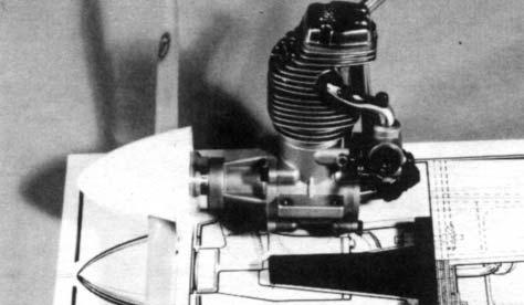
21 7. Tack-cement the engine between plastic engine bearers, holding it vertical and parallel to mounts. 9. Mount propeller and spinner on your engine. Position engine over fuse top view on plan and compare it to the installation shown. Back of spinner, should protrude about 1/8 beyond the cowl front as shown on the plan. Hold engine in this location. For long 4-cycle engines, check for at least 1/8 clearance between engine rear and firewall; to obtain this clearance the engine may have to be shifted forward as required. Measure the distance from the engine rear to the firewall. Write this measurement down it will be used later for engine mounting. Position engine/mounts on firewall for side mounted or inverted installation. Center-alignment marks are molded into engine mount bases; align these marks directly below the engine mounting flanges with the corresponding laser-marked line on firewall. Then measure and position mounts so they are equally spaced from second lasermarked line 10. Position one engine mount, butting its rear flange against the firewall location shown on the plan. Observe how the front engine mounting holes relate to the engine mount. If there is at least 1/4 of mount forward of this hole location, the spacer plate shown on the plan is not needed and you should proceed directly to step 11. If there is doubt that the mounts do not project far enough for adequate drilling and engine mounting, the spacer must be installed by completing the steps below. (Note for 4-cycle engines, make sure the spacer does not obstruct the carburetor, cut out spacer center if required for clearance). Mark straight down through holes in mounts. 8. Drill four 5/32 holes at marked locations. Position 1/4 x2-1/8 ply spacer on firewall so that it lies equally spaced over holes (trace spacer shape on firewall, to check position). Glue spacer in place. 21
 in same manner, using rubber bands to hold parts. 11.")
22 Turn firewall over, at hole locations, drill 5/32 holes through 1/4 spacer plate. 12b. Hold fuse tail ends up, carefully spread fuse rear open, and plug former E in place, hold with a rubber band. Working towards front, install formers C and D (balsa doublers facing in towards each other) in same manner, using rubber bands to hold parts. 11. Permanently install four blindnuts in back of firewall using socket head screws and washers to pull blindnuts up into the screw holes as shown (firewall with spacer plate shown for clarity). Remove screws after seating blindnuts. Glue blindnut flanges to firewall. 12c. With laser-cut separation at tail end facing down, insert top sheet under rubber bands at former B, and work it towards tail, slipping it under bands as you go. 12a. Place fuse sides one on the other, tape rear together around the back end. Spread fuse fronts apart, and plug former B 12e. Lock tabs at sides and ends of top sheet into corresponding notches in fuse sides. Hold parts with tape. 12f. Position bottom sheet in same manner, sliding it towards rear. into holes in body sides (doubler BB must face forward). Hold parts together with a rubber band. 13. Install firewall and pull fuse fronts together with tape as shown. 22

23 From 1/2 x1/2 triangular balsa, cut reinforcing gussets to fit behind firewall. Glue in place. 14. Place fuse over TOP VIEW on plan sheet. Viewing from above, carefully align the fuse to match plan outline. If an area of the fuse is off, adjust that position in the direction required. Tape parts to hold in position. 17. Set wing in place on fuse, then check and adjust until wing tips are equidistance from rear end. Project two lines straight forward from fuse sides on wing bottom. 15. When satisfied with alignment, permanently glue sides, formers and sheet parts in place. Apply a bead of CA along all joints inside and outside, or from both sides. Position a 1/8 ply bolt plate about 1/8 away from line and so that laser-marked line is aligned with T.E. joint as shown. Glue in place. Repeat for second bolt plate. In the case of formers-it will penetrate the joint and leave a slight reinforcing fillet. At tail end, glue bottom sheet to conform to slight bend in fuse sides. Measuring carefully 1-7/16 from wing T.E. and 9/16 in from fuse sides, drill two holes 5/32 dia. down through wing and bolt mounting blocks. Glue two large washers at hole locations. Remove wing from fuse. Install blindnuts in bottom of mounting blocks, pulling them up in place using screws and washers. Install wing using bolts. Check alignment of wing and fuse at front. At hole in former B, drill a 1/4 dia. hole about 3 deep into wing (try to hold drill square and level into wing). 16. Plug 1/8 laser-cut braces into slotted locations in fuse doublers and glue securely in place. Position and glue wing mounting blocks. reglue these joints thoroughly, the wing attaches here-it must be strong. Cut 1/4 x4-1/2 dowel to 3 length. Remove wing and glue this dowel securely into wing, leaving about 1/4 protruding. 23

24 22. A 1/8 square balsa strip must be glued to the fuselage top to serve as a gluing brace for the top sheeting. Since the front sheeting is thicker than the rear, the front strips are spaced differently than the rear as described below. 18. With laser-cut separation facing out, bend and position front bottom sheeting. Glue in place. From 1/8 square balsa strip cut two pieces to fit from bottom notch in former TC to TE. Keeping strips about 1/16 in from and parallel to fuse edge, glue to top. 19. Trial fit the tail wheel bracket at laser-cut separation in bottom sheet. Using a knife or small saw, make a slot for bracket flange as required for correct fit. DO NOT GLUE bracket in place at this time! Install remaining 1/8 balsa strip in bottom notches in former TC forward to firewall-position this strip 1/8 in from fuse side. 20a. Cut wing fairings from vac-formed sheets and try fitting them at L.E. and T.E. Cut out bottom of fairing holes and trim hole walls to match washers. Position fairings for best fit with fuse and glue to wing. 23. From 1/4 square balsa cut and glue three top sheeting supports to fit notches in formers TC, TD, and TE. Cut three more supports and glue to notches in forward formers TB, TA and firewall. 20b. From scrap 1/8 balsa, glue and trim lower tail end sheeting. 21. Install top formers TA, TB, TC, TD and TE in their respective slots in top fuse top (IMPORTANT: tilt formers TB and TC using gauge TBTC as shown below). 24. The three rear sheeting pieces are oversize wedge shapes and are designed to be shifted back and forth for best fit. Begin sheeting installation with one side. Slide sheet in position so lower edge butts against fuse side and upper edge fits about centered on 1/4 balsa support. When satisfied with fit, glue sheet in place (slight dampening of outer balsa surface will help curve it to fit fuse shape). 24 Install opposite side sheet in same manner. Trim sheets flush with front of former TC and rear of TE.

25 Slide top center sheet in position and glue in place. Trim to fit with side sheets. 26. Flat sand fuse and round off corners, except the following areas: top of tail mounting area, and wing saddle-repeat: do not sand these areas, except very lightly to remove burrs. 25. Install 1/8 laser-cut front sheeting in dame manner, applying side pieces first. Where 1/8 balsa butts against former TC glue a scrap of 1/8 sq. inside to reinforce the joint. 27. Carefully remove scrap areas from formed cockpit as shown above. Gently bend cockpit front, rear, and sides along formed seamsdo not bend sharp or plastic will crack. Temporarily place cockpit inside fuse, trimming as required for good fit. Remove cockpit and set aside for painting. 28. Bolt wing in place. 25 Center stab on fuse, measuring to obtain equal distance from side to side, and from nose of fuse to rear corner of each stab tip. View from rear to make sure that stab is level in respect to wing. Trial fit fin in place, making sure that it points dead straight ahead. When tail parts are aligned and square with fuse, make several reference marks. Remove fin and stab. Using slow CA or epoxy, glue stab and fin in place. While drying, check parts for square and alignment. Glue balsa filler pieces to fuse at front of stab.
. Carefully mark through engine mounting holes to mounts.")
26 COWL ASSEMBLY 29. Cut 7/8 sq.x16 balsa block into two 8 pieces. Then, taper sand to pointed fairing shape as shown in photos above and fuse views on plan. 1. Using the measurement from step 9, position and tack-cement engine on mounts (engine must parallel mounts and point straight out from firewall). Carefully mark through engine mounting holes to mounts. Remove engine. Drill four 1/8 holes straight into and through mounts. #6 x 3/4 screws Install engine, muffler, and propeller and spinner. 2a. Cut cowl halves apart at center. Trim to match formed curved lines as shown in photo above. Glue fairings in place. b. Cut out opening for prop shaft and front air intakes. 30. Refer to fuse views on plan for installation of rudder pushrod guide tube through balsa fairing. Using a sharpened 1/8 wire, drill a hole for the rudder pushrod guide tube through balsa fairing and former TE. Position nylon rudder and elevator guide tubes in fuse as shown on plan (insert long threaded rods to hold tubes straight). Glue nylon tubes in place where they exit fuse rear. From scrap ply, cut braces to support tubes at formers C to D. Glue tubes to former C. Remove wire rids and trim nylon tubes flush where they exit fuselage at rear. Later, when installing your radio equipment, we recommend running the receiver antenna into the rear of the fuse. To make this easier to do, glue a length of plastic tubing, drinking straws, etc. from former C to E. To protect the engine area from becoming oil soaked, it needs to be fuel-proofed. Either polyurethane, CA, or epoxy is good for this. Apply your fuel proofer to entire engine area, firewall, sides and fuse front. Open up screw holes with toothpick while paint is wet. Let dry thoroughly. 26 c. Try fitting cowl half in position over engine (allow about 1/8 space between cowl and spinner). Observe and mark where openings must be made in cowl for engine/muffler clearance. Begin making these openings, cut a little at a time, trying and fitting and enlarging openings as needed. Do not try to rush this or you may ruin the cowl or worse yet cut yourself. Try fitting other cowl half in place, cutting openings for engine/muffler as required.

27 Lower strip must be cut into small segments in order to fit around curves. d. When both cowl halves fit around engine, tape them together at center joint. Check for overall fit of cowl, match-up with spinner, etc. If cowls must be overlapped to fit, mark and trim the overlap until both halves butt fit at center joint. e. Glue cowl halves together. From long plastic strip furnished, cut and glue a joining tab along the inside edge of one cowl half as shown. General. A good covering job should be preceded by careful sanding, filling nicks and dents, then more sanding. Use filler appropriate for balsa such as CG Model Mate. Any irregularities in the wood surface will show on the covering so a smooth sanding job is a must for good appearance. For final sanding, use fine sandpaper (grade 240 to 320) and a sandpaper block. As mentioned earlier, the easiest way to finish your Chipmunk is to cover it in one color and then either paint it or apply the color scheme cut from covering material. Follow the manufacturer s instructions regarding applying multiple color paint schemes. If painting the color scheme, polyurethane spray paint is recommended. Now is a good time to paint the cowl and canopy frame detail so they can be set aside to dry while you are covering the airframe. Cowl should be sanded smooth and joints filled with material suitable for plastic. Wipe down completely with a tack rag to remove all dust. Mask areas to be painted. IV COVERING Attach cowl to fuse using #2 x 3/8 screws and washers. At lower side screw locations, make spacers from scrap ply to fill gap between cowl and fuse. Glue spacers to fuse sides. IMPORTANT! Raw fuel and engine oil residue, if allowed to puddle or stand, can eventually deteriorate the finish, resulting in loose edges of the covering and striping, peeling paint, etc. Wiping the model down after each flight will help maintain your plane s finish for years. Engine exhaust often affects details such as striping, etc. Careful applications of CA along the edges will hold them down securely in place. Read instructions on paint can, and follow them. The first coat should be applied very lightly. Do not try to cover in just one coat or the paint will run! Repeat applications, gradually building up color density while allowing time between coats as specified by the paint manufacturer. Let final coat set a bit, then remove the masking tape carefully. Set aside away from your work area so it can dry free from dust or other damage. PAINTING PLASTIC FILMS. Modeling grade polyurethane or epoxy paints are recommended. To assure good paint adhesion to the plastic covering, the area to be painted should be washed with soap and water to remove surface grease and oil. Then dry thoroughly. You can also clean the surface with acetone. The design is then carefully masked; vinyl tape is best for this. Optional: gently wipe masked area with 000 steel wool to dull plastic surface for increased paint adhesion, being careful not to disturb the masking tape. 27
28 28
29 29
30 30
31 31
32 32
33 33
34 34
35 35
FUSELAGE CONSTRUCTION
 FUSELAGE CONSTRUCTION Note: prior to building and gluing on the work surface use protective covering on your building surface. (wax paper or clear wrap) Fit the laser cut Fuselage Front and Fuselage Rear
Citabria Pro. Aerobatic Parkflyer. by Joel Dirnberger
 Citabria Pro Aerobatic Parkflyer by Joel Dirnberger Revision C: December 21, 2004 Citabria Pro Building Instructions Length: Wingspan: Wing Area: Flying Weight: Wing Loading: Functions: Specifications:
Piper Cherokee /3 scale. Construction Manual
 Piper Cherokee 140 1/3 scale Construction Manual STAB CONSTRUCTION 1. Remove foam cores from cradle and place on flat surface. Inspect pieces before you epoxy halves together making sure leading and trailing
LARK. Classic Legal Precision Stunter RSM DISTRIBUTION. presents. Charles Mackey. Wing Area 570sq. Wingspan 52.
 RSM DISTRIBUTION presents LARK By Charles Mackey Photo _ Bob Hunt Classic Legal Precision Stunter Wingspan 52 Length 39.5 Wing Area 570sq Motor 35-46 www.rsmdistribution.com Page 2 Thank you for purchasing
84 WING SPAN MESSERSCHMITT BF-109
 84 WING SPAN MESSERSCHMITT BF-109 (COPYRIGHT PROTECTED 2014) ALL RIGHTS RESERVED MEISTER 84 ME-109 SIERRA GEAR UPDATE PLEASE NOTE: THE MAIN GEAR MOUNTING PLATE FROM SIERRA IS NOT SQUARE. YOU HAVE TO ROUND
THE APOGEE A 100-INCH AMA DURATION SAILPLANE FROM DYNAFLITE
 THE APOGEE A 100-INCH AMA DURATION SAILPLANE FROM DYNAFLITE Apogee is the intermediate sailplane designed to be competitive in AMA duration contests. Effective spoilers, rudder and full flying stabilizer
LANIER - Ultimate Pitts - INSTRUCTIONS. Additional Parts Required. (12) 4-40 blind nuts (Dubro #606)
 4-40 blind nuts (Dubro #606)") Additional Parts Required (4) or more channel radio with 7-8 servos..91-2.2 two stroke or 1.20-1.84 four stroke engine Appropriate Master Airscrew prop and Hayes mount for your engine. 3 Tru-Turn spinner
Additional Parts Required (4) or more channel radio with 7-8 servos..91-2.2 two stroke or 1.20-1.84 four stroke engine Appropriate Master Airscrew prop and Hayes mount for your engine. 3 Tru-Turn spinner
(Build Instructions)
") (Build Instructions) Specifications * Wingspan: 58cm * Length: 50cm * Flying Weight: 59 grams * Channels: 3 (Rudder Elevator Throttle) * Suggested Receiver: 4Ch Micro * Motor: 8mm GearDrive * Prop: GWS
(Build Instructions) Specifications * Wingspan: 58cm * Length: 50cm * Flying Weight: 59 grams * Channels: 3 (Rudder Elevator Throttle) * Suggested Receiver: 4Ch Micro * Motor: 8mm GearDrive * Prop: GWS
SZD-10 bis CZAPLA ASSEMBLY MANUAL IN PICTURES
 1 RUDDER Plan and parts: 2 Assembly steps: Photo above: glue together rudder spar, ribs and trailing edge. Clamp spar to a flat surface (chipboard on the photo) and make sure the straight aligment of the
BUILDING THE A6M2 ZERO
 BUILDING THE A6M2 ZERO Product Support (Do Not Remove From Department) TOP FLITE MODELS, INC CONGRATULATIONS' You now own the most accurate R/C Stand-Off Scale kit ever produced We at Top Flite hope that
96 WING SPAN SPITFIRE (COPYRIGHT PROTECTED 2014) ALL RIGHTS RESERVED
 ALL RIGHTS RESERVED") 96 WING SPAN SPITFIRE (COPYRIGHT PROTECTED 2014) ALL RIGHTS RESERVED GENERAL INSTRUCTIONS Should you elect to use the recommended Door Skin, which is 1/8 mahogany plywood measuring 36 x 88. Have it cut
96 WING SPAN SPITFIRE (COPYRIGHT PROTECTED 2014) ALL RIGHTS RESERVED GENERAL INSTRUCTIONS Should you elect to use the recommended Door Skin, which is 1/8 mahogany plywood measuring 36 x 88. Have it cut
PITTS S2S CONSTRUCTION
 PITTS S2S CONSTRUCTION FUSELAGE CONSTRUCTION 1) Place the right fuselage side over the plan and mark the former positions. Place the left side over the right side and mark the former positions. Glue F1
LANDING GEAR. 1. Fit landing gear into slots on bottom of fuselage.
 LANDING GEAR 1. Fit landing gear into slots on bottom of fuselage. 4. Use channel-lock pliers to press blind nuts into position (note: drilled hole should be slightly smaller than shaft of blind nut for
SPUNKY ASSEMBLY MANUAL
 SPUNKY ASSEMBLY MANUAL Please read the tips section at the back of this manual regarding the use of laser cut parts. The proper removal and preparation of these parts is important. When laser cut, some
RESolution V2 Manual
 RESolution V2 Manual Note for the German Manual: Yellow Bottle thick CA Pink Bottle Med CA Blue tube 5 minute Epoxy Green tube 90 Minute Epoxy Construction of the Fuselage Step 1: Cover the plan with a
MECOA EZ-4061 Trainer
 MECOA EZ-4061 Trainer EZ-4061 is a newly designed, Almost Ready to Fly kit. It is an extremely easy to control trainer with strong construction and excellent aerodynamic performance. This is a great choice
90 WING SPAN P-51D MUSTANG (COPYRIGHT PROTECTED 2014) ALL RIGHTS RESERVED
 ALL RIGHTS RESERVED") 90 WING SPAN P-51D MUSTANG (COPYRIGHT PROTECTED 2014) ALL RIGHTS RESERVED GENERAL INSTRUCTIONS This design is basically an enlargement of the very popular fun scale Mustang 60 Size. You can build it light
90 WING SPAN P-51D MUSTANG (COPYRIGHT PROTECTED 2014) ALL RIGHTS RESERVED GENERAL INSTRUCTIONS This design is basically an enlargement of the very popular fun scale Mustang 60 Size. You can build it light
Parts Identification
 We are excited to introduce the Model Aero Aqua Sport. This is an excellent sport flyer, equally at home flying from grass fields, water, or even snow! The unique V-tail gives the Aqua Sport a distinctive
JAMISON SPECIAL. Building Guide
 JAMISON SPECIAL Building Guide WING Mark then drill holes for wing jig rods. Slide Ribs onto jig rods Mark the rib positions on 1/16 x 1 trailing edge, 1/4 x 1/4 leading edge & 1/4 x 1/4 spars Pin ribs
C-180 Builder s Manual
 C-180 Builder s Manual. May 20, 2002 Last revised July 11, 2002 Copyright! 2002 Douglas Binder, Mountain Models www.mountainmodels.com sales@mountainmodels.com (719) 630-3186 1 Required Equipment! Xacto
Millennium RC presents The New and Improved (now even easier to build and cover!) SSX X-Trainer Build Kit
 SSX X-Trainer Build Kit") Millennium RC presents The New and Improved (now even easier to build and cover!) SSX X-Trainer Build Kit Wing span: Approx. 42 Wing Area: 504 sq. in. Wing Loading: 6.71 oz/ sq. ft. Introduction: The Slow
Millennium RC presents The New and Improved (now even easier to build and cover!) SSX X-Trainer Build Kit Wing span: Approx. 42 Wing Area: 504 sq. in. Wing Loading: 6.71 oz/ sq. ft. Introduction: The Slow
Super Sky Surfer 2000 Assembly Instructions
 Super Sky Surfer 2000 Assembly Instructions Note: Plug and Play version of the Sky Surfer comes with fuselage pre-glued and motor/servos installed. If you wish to route antennas or wires through the tail,
Hobby Lobby Zip Supplementary instructions Please refer to the included drawings while using these assembly instructions
 Materials needed: 15 or 30 minute epoxy Medium CA Masking tape Scotch tape Servo Tape Wax paper Tools Needed: Pencil or marker Flat building surface Hobby knife or razor blade 7/64" or 3mm drill bit 3/16"
Stearman PT-17 KIT WARRANTY
 Stearman PT-17 KIT # K-306 Assembly Instructions Version 2 02-17-16 Designed by Tom Herr WARRANTY Sig Manufacturing Co, Inc. guarantees this kit to be free from defects in both material and workmanship
Stream NXT - assembly instructions
 Stream NXT - assembly instructions Recommended settings CG (measured from root leading edge): Speed/launch camber (+down, near the wing root): Cruise camber (+down, near the wing root): Thermal camber
We re sure that you will enjoy countless hours of flying fun with your Goldberg Cub, just as generations of pilots have had with theirs!
 Cub Instructions There really is nothing like a Cub! The C.G. version retains the honest, easy to fly qualities that made the full size airplane famous. With the standard long wing, the model is a very
COMET 24" HELLCAT REPRODUCTION ASSEMBLY GUIDE
 COMET 24" HELLCAT REPRODUCTION A RUBBER POWERED 24" WING SPAN MODEL BY PAUL BRADLEY ASSEMBLY GUIDE AUGUST 2016 CHANGES MADE TO THE ORIGINAL The following changes were made to the original Comet kit structural
ParkJet Builder s Manual
 ParkJet Builder s Manual Thank you for purchasing the ParkJet. The ParkJet is a profile ducted fan airplane that can be flown in a larger park. The ParkJet was initially designed by Scott Stoops and modified
Building Tips This model can be built using the following types of adhesives:
 Page 1 Building Tips This model can be built using the following types of adhesives: Epoxy (with or without microballons) Odorless cyanoacrylate (CA) with accelerator UHU Creativ for Styrofoam (or UHU
Your kit contains the following parts. Please check your kit for any missing or damaged parts before starting construction.
 Your kit contains the following parts Please check your kit for any missing or damaged parts before starting construction COMPLETE KIT PARTS LIST 1 Plan Sheet #1 1 Plan Sheet #2 2 Decal Sheet 2 White Tissue
E-AERO EPP PITTS KIT From BP HOBBIES. Parts Included in kit
 E-AERO EPP PITTS KIT From BP HOBBIES Parts Included in kit Thank you for purchasing the BP Hobbies/E-aero EPP Pitts. Please take the time to read through the instruction manual before beginning the build.
RSM DISTRIBUTION Presents
 RSM DISTRIBUTION Presents MOSQUITO By Jack Sheeks Photo _ Jack Sheeks Semi Scale Twin Stunter Wing Span: 58" Length: 37-3/4 Area: 579 sq. in. Engine: Two.35 -.40 www.rsmdistribution.com Call (951) 678
This pictorial document contains assembly recommendations including some fit and finish details that will be helpful when building this airplane
 This pictorial document contains assembly recommendations including some fit and finish details that will be helpful when building this airplane Problems found with this kit and a flight performance review
ULS Cherokee. Ultra Low Speed aircraft for indoor RC flying. Zippkits. Specifications: Required to complete:
 Zippkits ULS Cherokee Ultra Low Speed aircraft for indoor RC flying. Specifications: Span- 28 inches Wing Area- 151 Sq/In Wing Loading- 3.0 ounces/ft Weight- 3.5 ounces RTF Build time- 1-2 Hours Radio-
Switchback Sport Builder s Manual
 Switchback Sport Builder s Manual Thank you for purchasing the Switchback Sport. The Switchback Sport has been designed for the novice to intermediate pilot who wants a plane with good performance that
Introducing The Cloud Models Westland Whirlwind
 Produced by Cloud Models,Deopham Road,Morley,Wymondham, Norfolk,NR18 9AA E-mail sales@cloudmodels.com web site cloudmodels.com Introducing The Cloud Models Westland Whirlwind By Tricks Thank you for purchasing
FLITZEBOGEN-2 Assembly instructions
 FLITZEBOGEN-2 Assembly instructions Trim the end of the fuselage to the length of 925mm from the nose. Be careful to avoid splitting the carbon fibers. Sand the base of the stab mount in preparation for
MOUNTAIN MODELS P-51 Mustang. 1/12 Scale Electric Park Flyer. Copyright Mountain Models
 1 MOUNTAIN MODELS www.mountainmodels.com P-51 Mustang 1/12 Scale Electric Park Flyer Wingspan: 37, Wing Area: 254 sq. in., Weight: 15 to 19.5 oz Instructions Version 1.4, May 23, 2007 Kit Contents: 2 1.
LANIER Dominator INSTRUCTIONS
 ADDITIONAL EQUIPMENT NEEDED TO COMPLETE YOUR DOMINATOR 500 General 3.2 to 4.2 Size two stroke R/C engine, muffler, and engine mount Gas or glow fuel line Minimum of 4 channel radio set required (4-5) 70
Note - the nose ribs and are thinner than the main ribs. These nose ribs will use a thinner rib cap than the ribs. This is per design.
 Stabilizer rev 1.2 The SE5a stabilizer is the heartbeat of the tail and is recreated like the full scale version. All tail pieces depend on the stabilizer. It uses the steel fittings, pulleys, inspection
Taylorcraft Indoor / Cul-De-Sac Flyer
 Taylorcraft Indoor / Cul-De-Sac Flyer Taylocraft Specifications Wingspan: 28.0 in. Wing Area: 117 sq. in. Weight (Ready to Fly): 3.0 3.1 oz. Wing Loading: 3.7 3.8 oz. / sq. ft. LIABILITY RELEASE In that
BUILDING THE FUSELAGE FRAME 6
 KIT 305 DHC-2 BEAVER COPYRIGHT 2011 BY PAUL K. GUILLOW, INC. WWW.GUILLOW.COM Before starting the construction of your model, study the plan and construction procedure carefully so that you will have a
Corvus Racer CC
 Corvus Racer 540 35CC Item No:L-G035008 Specifications Wing Span Length Wing Area Flying Weight Glow Gasoline Electric Radio mm mm 1200sq in (77.4sqdm) 9.9-12lbs(4.5-5.5kg) 91-1.20(2C) 1.10-1.40(4C) 20-40cc
Sig Mfg. Co., Inc South Front Street...Montezuma, Iowa 50171
 Sig Mfg. Co., Inc...401-7 South Front Street...Montezuma, Iowa 50171 Introduction The SEALANE takes off and lands on water just as easy as the Sig Kadet LT40 does on solid ground. Gentle, graceful, sure
LANIER - Giles % - INSTRUCTIONS
 Additional Parts Required (4) or more channel radio with 4 servos..25 -.36 two stroke or.40 -.52 four stroke engine Appropriate Master Airscrew prop and Hayes mount for your engine. 2-1/2 Tru-Turn spinner
Thank you for your purchase of the Lee Ulinger, FoamtanaS, Yak-55, or Extra 330 3D Depron foam, Aerobatic airplane.
 Thank you for your purchase of the Lee Ulinger, FoamtanaS, Yak-55, or Extra 330 3D Depron foam, Aerobatic airplane. Tools you will need to build Recommended additional items: #11 hobby knife Motor: Hacker
Pfalz E1 Monoplane 48 EZ Build Version
 Pfalz E1 Monoplane 48 EZ BUILD Pfalz E1 Monoplane 48 EZ Build Version R/C Scale Model Instructions CONTACT INFORMATION Designed by M.K. Bengtson Prototype by Robert Hoffman Manufactured and Distributed
SwitchBack Senior. SwitchBack Senior Specifications
 SwitchBack Senior SwitchBack Senior Specifications Wingspan: 55.4 in. Length: 41 in. Wing Area: 597 sq. in. Weight (Ready to Fly): 34 to 37 oz. Wing Loading: 8.2 to 8.9 oz. / sq. ft. Version 1.05, March
10. Wing prep and subassembly
 Date Section Objective: Construct and fabricate the sub-assemblies of the wing panel. Required Parts: Wing left 11gal PN104-300, Wing right 1gal PN104-400, Wing left 15 gal option PN104-322, Wing right
FORWARD FUSELAGE SIDES & REAR TOP SKINS
 FORWARD FUSELAGE SIDES & REAR TOP SKINS WORK REPORT Step No. Check Parts / Tools Qty Preparations. 1 [ ] 6F5-3 Upper Front Longerons 2 2 [ ] 6F5-5 Heel Support 1 3 [ ] 6F5-2 Front Floor Skin 1 3 [ ] Firewall
SASKATOON, Saskatchewan
 CONSTRUCTION GUIDE AVRO ARROW (CONTEST VERSION) Copyright, Bill Jones, 2004 SASKATOON, Saskatchewan This is a work in progress, so there are a couple of rough areas ( I ll point out those that I m aware
TWEETY 25 INSTRUCTION MANUAL. Almost Ready to Fly Nitro/Electric Aerobat FEATURES SPECIFICATIONS
 TWEETY 25 Almost Ready to Fly Nitro/Electric Aerobat INSTRUCTION MANUAL SPECIFICATIONS FEATURES WINGSPAN: 45.7 (1160mm) LENGTH: 38.6 (980mm) WING AREA: 370 sq in(24 sq dm) FLYING WEIGHT: Approx. 3.3 lbs
BUILDING INSTRUCTIONS FOR FINEWORX. Miles. 2M Class Competition Glider. Congratulations! You have purchased our Miles, 2M Class Competition Glider.
 BUILDING INSTRUCTIONS FOR FINEWORX Miles 2M Class Competition Glider Congratulations! You have purchased our Miles, 2M Class Competition Glider. The Miles is the first offering from FINEWORX, a new company
LANIER - Double Trouble - INSTRUCTIONS. Tail 1 T1 ¼ Balsa 1 T2 ¼ Balsa 2 T3 ¼ Balsa 1 T4 ¼ Balsa 1 T5 ¼ Balsa 1 T6 ¼ Balsa 2 J1 ¼ Balsa 2 J2 Lite ply
 Tail 1 T1 ¼ Balsa 1 T2 ¼ Balsa 2 T3 ¼ Balsa 1 T4 ¼ Balsa 1 T5 ¼ Balsa 1 T6 ¼ Balsa 2 J1 ¼ Balsa 2 J2 Lite ply Other Parts 2 Aluminum Gear 1 3/32 Music wire tail skid 2 Elevator and J-plane joiner wire
Cobra X Q Construction Tips Construction: Bel y pan
 Cobra X Q Construction Tips : The white plastic in this kit is high impact styrene. It can be painted with most types of coatings if light coats are applied this is necessary due to the thickness of the
uin RC FPRC ZERO Specificationss Empty Weight
 Flying Pengu uin RC FPRC ZERO Specificationss Wing Span 42.75 (1085 mm) Fuselage length 30.5 ( 775 mm) Empty Weight 9.5 10 oz. (150 160g) Estimated Flying Weight 20 255 oz. (320 400g) Wing Area: 151 sq.
WRIGHT FLYER 1 INSTRUCTIONS FOR THE D10LC KIT
 WRIGHT FLYER 1 INSTRUCTIONS FOR THE D10LC KIT Manufactured in the USA by Easy Built Models PO Box 681744, Prattville, AL 36068-1744 Visit us at www.easybuiltmodels.com Easy Built Models GLUE METHODS Always
84 WING SPAN MESSERSCHMITT BF WIN G S P A N
 84 WING SPAN MESSERSCHMITT BF-109 10 2 WIN G S P A N MESSERSCHMITT BF-109 THIS IS A VERY EASY PLANE TO BUILD BEFORE YOU START The fuselage self jigging system used an easy accurate assembly. But, attention
1/6 PA-25 PAWNEE. *Specifications are subject to change without notice.*
 1/6 PA-25 PAWNEE INSTRUCTION MANUAL [ A335 Kit ] Wing Span : 72 in / 1830 mm Wing Area : 736 sq in / 47.5 sq dm Flying Weight : 6.6 lbs / 3000 g Fuselage Length : 48 in / 1220 mm Requires : "Glow Power"
EXTRA 330SC 60CC. Item No:H G Specifications cc gas DA50,DA60, DLE55, DLE60(twin), 3W55. Description
, 3W55. Description") EXTRA 330SC 60CC Item No:H G060011 Specifications Wing Span Length Wing Area Flying Weight Gasoline Radio Description Carbon Fibre : 92" (2347mm) 84 1/2 " (2060mm) 1526.8 sq in(98.5sq dm) 16 17lbs(7300
EXTRA 330SC 60CC Item No:H G060011 Specifications Wing Span Length Wing Area Flying Weight Gasoline Radio Description Carbon Fibre : 92" (2347mm) 84 1/2 " (2060mm) 1526.8 sq in(98.5sq dm) 16 17lbs(7300
TIGER MOTH 120 ASSEMBLY INSTRUCTIONS
 TIGER MOTH 120 ASSEMBLY INSTRUCTIONS SPECIFICATIONS Wing Span: Length: Radio: Flying Weight: 1920mm 1580mm 4 channel with 6 servos 4200g AILERON ASSEMBLY 1 Start by removing the servo cover from the bottom
Dandy Sport Builder s Manual
 Dandy Sport Builder s Manual Thank you for purchasing the Dandy Sport. The Dandy Sport has been designed as an easy to build aileron trainer. Take your time and enjoy building this plane. Specifications:
Combat plane for Open B Lanier R/C Inc. P.O. Box 458 Oakwood, GA Phone Fax copyright 2003 Lanier R/C
 Combat plane for Open B Lanier R/C Inc. P.O. Box 458 Oakwood, GA. 30566 Phone 770 532 6401 Fax 770 532 2163 copyright 2003 Lanier R/C Important information: Please inspect the plane before beginning to
100 WING SPAN MESSERSCHMITT BF-109 (COPYRIGHT PROTECTED 2014) ALL RIGHTS RESERVED
 ALL RIGHTS RESERVED") 100 WING SPAN MESSERSCHMITT BF-109 (COPYRIGHT PROTECTED 2014) ALL RIGHTS RESERVED BEFORE YOU START The fuselage self jigging system used an easy accurate assembly. But, attention to detail when cutting
100 WING SPAN MESSERSCHMITT BF-109 (COPYRIGHT PROTECTED 2014) ALL RIGHTS RESERVED BEFORE YOU START The fuselage self jigging system used an easy accurate assembly. But, attention to detail when cutting
High performance 90mm fiberglass jet
 High performance 90mm fiberglass jet Assembly manual For intermediate and advanced fliers only! Specs Wingspan: 1255mm Fuselage length: 1250mm Flying weight: 2600-3000g Wing area: 22.6 dm² Wing loading:
RYAN STA SAFETY PRECAUTIONS. "Sport Scale E-Power ARF" For Intermediate and Advanced Fliers. This radio control model is not a toy!
 RYAN STA "Sport Scale E-Power ARF" For Intermediate and Advanced Fliers. SAFETY PRECAUTIONS This radio control model is not a toy! First-time builders should seek advice from people with model building
THE SWALLOW. An interesting, simple, all-balsa speedster of crashproof design. by MALCOLM J. ABZUG
 THE SWALLOW An interesting, simple, all-balsa speedster of crashproof design. by MALCOLM J. ABZUG DESIGNED primarily for the purpose of testing a new type of monocoque fuselage design, the Swallow proved
I hope you enjoy the Spirit as much as I have. Scott DeTray Model Aero
 We are excited to introduce the Model Aero Spirit. Inspired by the magnificent Northrop Grumman B-2 Spirit Stealth Bomber, the Spirit is a great flyer, on land or water. It tracks like an arrow and is
Edge 540 V3 35CC. Scheme A. Item No:L G Specifications. Flying Weight
 Edge 540 V3 35CC Item No:L G035016 Specifications Wing Span Length Wing Area Flying Weight Glow Gasoline Electric Radio Description 76 (1930mm) 74 (1879mm) 1200sq in(77.4sqdm) 9.9 12lbs(4.5 5.5kg) 91 1.20(2C)
Tough warrior. The author's many years of intensive competition are your guarantee of a sturdy, fliable design with all "bugs" eliminated.
 Tough warrior. The author's many years of intensive competition are your guarantee of a sturdy, fliable design with all "bugs" eliminated. LAST month we described the construction of the fuselage and motor
30% Edge 540T Almost Ready to Fly
 Lanier R/C 30% Edge 540T Almost Ready to Fly WARNING! THIS IS NOT A TOY! THIS IS NOT A BEGINNERS AIRPLANE This R/C kit and the model you will build from it is not a toy! It is capable of serious bodily
Fokker Dr1 Master Instructions
 Fokker Dr1 Master Instructions Rev 1 Congratulations on your new project. This Dr1 kit is the finest to date. The construction of the plane is similar and exactly like the original. Take your time and
HIGH-END TECHNOLOGY. Electric ducted fan Starfighter
 HIGH-END TECHNOLOGY RC Electric ducted fan Starfighter First we want to thank and congratulate you with your decision in buying one of our Kits. The Starfighter puts together very easily so there is not
Instruction Manual. Specification:
 Instruction Manual H I G Specification: Wingspan: 133 cm (52.3 inches) Length : 104 cm (40.9 inches) Weight : 1830gr Engine : 25-32 two stroke Radio : 4 channel - 4 servo H W I N G KIT CONTENTS: We have
S.E.5a (Build Instructions)
") S.E.5a (Build Instructions) Specifications Wingspan: 38 cm Length: 31cm Flying Weight: 41 Channels: 3 (Rudder Elevator Throttle) Suggested Receiver: 3Ch Brick Motor: 7mm Geared Motor Airframe Only Kit
S.E.5a (Build Instructions) Specifications Wingspan: 38 cm Length: 31cm Flying Weight: 41 Channels: 3 (Rudder Elevator Throttle) Suggested Receiver: 3Ch Brick Motor: 7mm Geared Motor Airframe Only Kit
Magpie. Foam Trainer. Magpie Specifications
 Magpie Foam Trainer Magpie Specifications Length: 34in. Wingspan (SF): 46in. Wing Area (SF): 414in 2 Wingspan (SP): 40in. Wing Area (SP): 360in 2 Weight (without battery): 12oz. Thank you for purchasing
INSTRUCTION MANUAL BOOK.
 INSTRUCTION MANUAL BOOK. SPECIFICATION Wingspan : 164 cm 64.57in. Length : 135 cm 53.15 in. Weight : 3.3kg 7.26 lbs. Servo : 7 servos. Radio : 4 channels. Engine : 61 cu.in-2 stroke. 91 cu.in-4 stroke.
LANIER R/C. Stinger WARNING! THIS IS NOT A TOY! THIS IS NOT A BEGINNERS AIRPLANE LIMITED WARRANTY
 LANIER R/C Stinger WARNING! THIS IS NOT A TOY! THIS IS NOT A BEGINNERS AIRPLANE This R/C kit and the model you will build from it is not a toy! It is capable of serious bodily harm and property damage.
Messerschmitt Bf 109F-2 Version January 2005
 Assembly Manual for Messerschmitt Bf 109F-2 Version 1.2 29 January 2005 Designed by Terry Majewski Copyright 2005 Thomas A. Jacoby and WarbirdKits.com 1 Materials Kit Contents This kit includes the following
STANDARD CANOPY WORK REPORT B-1
 STANDARD CANOPY WORK REPORT B-1 No. Check Parts / Tools Qty _ Canopy Lock 1 [ ] 6E2-3 Canopy Hinge Block 1 2 [ ] 6E4-5 Canopy Side Frame 2 2 [ ] 6E2-1 Canopy Lock Assembly 1L + 1R 3 [ ] 6E2-4 Rear Lock
1. Build the bottom first - make sure your table is flat. Build the entire plane using foam safe CA and kicker. The best technique is to spray kicker
 Wxá zç uç `tçué 1. Build the bottom first - make sure your table is flat. Build the entire plane using foam safe CA and kicker. The best technique is to spray kicker on one part and apply a sparing amount
Corvus Racer Colour schemes. AeroPlus RC Copyright 2013 All Rights Reserved
 Corvus Racer 540 59 Item No:A E050003 Specifications WING SPAN: 59"(1500mm) LENGTH: 54.1"(1374mm) WING AREA: 654sq.in.(42.2sq.dm.) FLYING WEIGHT: 4.6 5.3lbs(2000 2300g) Electric:Brushless outrunner 8Oz.
4. Bevel the LE face of HS1-HS11 to match the horizontal stab leading edge sweep angle.
 BEFORE YOU BUILD 1. Unroll each sheet of the plans. Roll them inside out so that they will lie flat on the building surface. 2. Assemble the tools that you will need to build each section so that they
Plastic Trainer-19. I have tried to only use materials available from the big box building centers like Home Depot, Rona (Canada) and Lowe s.
 and Lowe s.") Plastic Trainer-19 I have tried to only use materials available from the big box building centers like Home Depot, Rona (Canada) and Lowe s. The picture above shows the prototypes with an original Cox
Plastic Trainer-19 I have tried to only use materials available from the big box building centers like Home Depot, Rona (Canada) and Lowe s. The picture above shows the prototypes with an original Cox
Building Instructions P-51 BF109
 Building Instructions P-51 BF109 Sport model for.015 engines. Legal for SSC Warbird Lanier R/C Inc. P. O. Box 458 Oakwood, Ga. 30566 Copyright 2004 Lanier R/C Inc. Important information: Please inspect
THE STREAMLINER! A super Class D fuselage model
 THE STREAMLINER! A super Class D fuselage model by CHRISTIAN D. BERGER THE two most important characteristics of a contest model are its climb, and gliding ability. For, after all, you have to get up high
Kam Aero 43% Extra 300.
 Stab Sheeting Kam Aero 43% Extra 300. Stabs / Elevator: Make your skins using the same method as you did for the fuselage foam parts. The stabs require 8 sheets (4 per stab) of 4 x 48 A grain sheeting.
Falke Build Instructions
 A totally unofficial translation of the Falke Build Instructions The Falke (falcon) mini DLG is produced and marketed by Modellbau Thiele, Germany (www.modellbau-thiele.de), email webmaster@modellbau-thiele.de.
12. Wings, Flaps, Ailerons and Struts
 12. Wings, Flaps, Ailerons and Struts Fit Aileron Hinges Reference: Drawing 20270K2 Photo 12.1 Parts Required: 2007092 Aileron LS 200809N Aileron RS 2001394 Hinge 3/16 A1 (4) 2001694 Hinge Pin (4) PH0059N
ULTRA-SPORT 40 INSTRUCTION BOOK
 ULTRA-SPORT 40 INSTRUCTION BOOK PLEASE READ THROUGH THIS INSTRUCTION BOOKLET IN ITS ENTIRETY BEFORE BEGIN- NING ASSEMBLY. IT CONTAINS IMPORTANT INSTRUCTIONS AND WARNINGS CONCERNING THE ASSEMBLY AND USE
ULTRA SPORT 60 INSTRUCTION BOOK
 ULTRA SPORT 60 INSTRUCTION BOOK PLEASE READ THROUGH THIS INSTRUCTION BOOKLET IN ITS ENTIRETY BEFORE BEGINNING ASSEMBLY. IT CONTAINS IMPORTANT INSTRUCTIONS AND WARNINGS CONCERNING THE ASSEMBLY AND USE OF
Specifications Wingspan: 43cm Flying Weight: 33 grams (with battery) Channels: 3 Suggested Receiver: 4Ch Micro Motor: 7mm Brushed Geardrive
 Channels: 3 Suggested Receiver: 4Ch Micro Motor: 7mm Brushed Geardrive") Specifications Wingspan: 43cm Flying Weight: 33 grams (with battery) Channels: 3 Suggested Receiver: 4Ch Micro Motor: 7mm Brushed Geardrive Airframe Kit (Included Contents) * Airframe Parts Sheets (Depron)
Specifications Wingspan: 43cm Flying Weight: 33 grams (with battery) Channels: 3 Suggested Receiver: 4Ch Micro Motor: 7mm Brushed Geardrive Airframe Kit (Included Contents) * Airframe Parts Sheets (Depron)
SUKHOI SU-26 INSTRUCTIONS
 SUKHOI SU-26 INSTRUCTIONS When it was introduced, the outstanding Russian SUKHOI took the aerobatic world by storm! Never before have aerobatic enthusiasts had a machine so capable that it appears to have
Cover the wing trailing edge and the aileron leading edge with strapping tape as shown.
 Cover the wing trailing edge and the aileron leading edge with strapping tape as shown. The aileron hinges are done using strapping tape on the top and bottom surfaces of the ailerons as shown. Make sure
Continue gluing the remaining top parts ensuring the angled piece is glued well. Set aside and let dry. See photo below
 Radiator rev 1.1 The SE5a s radiator is one of the most recognized radiators in WW1. It is one of the components that defines the SE5a. The original SE5a has seen multiple radiator designs used during
A Class A Gas Model That Looks Like a Full Scale Plane and Performs Like a Contest Ship
 A Class A Gas Model That Looks Like a Full Scale Plane and Performs Like a Contest Ship By SAL TAIBI 1941 NATIONAL WINNER The little plane glides in with all the realism of a full scale craft The plans
Instruction Manual book
 Instruction Manual book ITEM CODE BH53. SPECIFICATION Wingspan : 1,250mm 49.21 in. Length : 930mm 36.61in. Weight : 1.1kg 2.42 Lbs. Parts listing required (not included). Battery: 3 CELLS-LI-POLY-11.1V-2,500
F100 Super Sabre instructions.
 F100 Super Sabre instructions. The F100 is a Jet model for the Wemotec 480 Minifan. Start with taking the parts out of the sheet and sand of the connection tabs. Instructions RBCkits F100 Super Sabre 1
The Olympic DLG. (Discus launch glider) by Chris Brislin
 by Chris Brislin") The Olympic DLG (Discus launch glider) by Chris Brislin 1 Contents Parts List/ What you need 3 Before you begin 4 Wing Construction 5-9 Pod Construction 9-13 Tail assembly 13-? Control linkages 9-10 Finishing
The Olympic DLG (Discus launch glider) by Chris Brislin 1 Contents Parts List/ What you need 3 Before you begin 4 Wing Construction 5-9 Pod Construction 9-13 Tail assembly 13-? Control linkages 9-10 Finishing
FUJI FA-200 AERO SUBARU
 FUJI FA-200 AERO SUBARU SEMI SCALE SPORT MODEL AERO SUBARU Assembly and Operations Manual Please review this manual throughly Before assembling or Operating The AERO SUBARU Semi scale sport model We ve