MUSTANG P-51. Hand-made Almost Ready to Fly R/C Model Aircraft ASSEMBLY MANUAL
|
|
|
- Corey Jones
- 6 years ago
- Views:
Transcription

1 MUSTANG P-51 Hand-made Almost Ready to Fly R/C Model Aircraft ASSEMBLY MANUAL Specifications Wingspan in cm. Wing area sq.in sq.dm. Weight lbs kg. Length in cm. Recommended engine size cu.in stroke..52 cu.in stroke. Radio System required 4 channel with 6 digital servos. Flying skill level Intermediate/advanced. Kit features. Ready-made minimal assembly & finishing required. Ready-covered covering. Photo-illustrated step-by-step Assembly Manual. Made in Vietnam.
2 MUSTANG P-51. Instruction Manual. INTRODUCTION. Thank you for choosing the MUSTANG P-51 ARTF by SEAGULL MODELS. The MUSTANG P-51 was designed with the intermediate/advanced sport flyer in mind. It is a semi scale airplane which is easy to fly and quick to assemble. The airframe is conventionally built using balsa, plywood to make it stronger than the average ARTF, yet the design allows the aeroplane to be kept light. You will find that most of the work has been done for you already.flying the MUSTANG P-51 is simply a joy. This instruction manual is designed to help you build a great flying aeroplane. Please read this manual thoroughly before starting assembly of your MUSTANG P-51. Use the parts listing below to identify all parts. WARNING. Please be aware that this aeroplane is not a toy and if assembled or used incorrectly it is capable of causing injury to people or property. WHEN YOU FLY THIS AEROPLANE YOU ASSUME ALL RISK & RESPONSIBILITY. If you are inexperienced with basic R/C flight we strongly recommend you contact your R/C supplier and join your local R/C Model Flying Club. R/C Model Flying Clubs offer a variety of training procedures designed to help the new pilot on his way to successful R/C flight. They will also be able to advise on any insurance and safety regulations that may apply. ADDITIONAL ITEMS REQUIRED cu.in 2-stroke engine..52 cu.in 4-stroke engine. Radio with six servos. Glow plug to suit engine. Propeller to suit engine. Protective foam rubber for radio system. Silicone fuel line. TOOLS & SUPPLIES NEEDED. Thick cyanoacrylate glue. 30 minute epoxy. 5 minute epoxy. Hand or electric drill. Assorted drill bits. Modelling knife. Straight edge ruler. 2mm ball driver. Phillips head screwdriver. 220 grit sandpaper. 90 square or builder s triangle. Wire cutters. Masking tape & T-pins. Thread-lock. Paper towels. PARTS LISTING. FUSELAGE ASSEMBLY (1) Fuselage. (1) Canopy hatch. WING ASSEMBLY (1) Right wing half with pre-installed aileron. (1) Left wing half with pre-installed aileron. (1) Plywood dihedral brace. Tail section assembly (1) Horizontal stabilizer with preinstalled elevator halves. (1) Vertical stabilizer with preinstalled rudder halves. Some more parts. HARDWARE PACK COWLING Landing gear... 2


3 NOTE: To avoid scratching your new aeroplane we suggest that you cover your workbench with an old towel. Keep a couple of jars or bowls handy to hold the small parts after you open the bags. Please trial fit all parts. Make sure you have the correct parts and that they fit and are aligned properly before gluing! This will ensure proper assembly as the MUSTANG P-51 is made from natural materials and minor adjustments may have to be made. The paint and plastic parts used in this kit are fuel proof. However, they are not tolerant of many harsh chemicals including the following: paint thinner, cyano-acrylate glue accelerator, cyanoacrylate glue de-bonder and acetone. Do not let these chemicals come in contact with the colours on the covering and the plastic parts. 3

Deflect the aileron and completely saturate each hinge with thin C/A glue. The ailerons front surface should lightly contact the wing during this procedure.")


4 MUSTANG P-51. Instruction Manual. HINGING THE AILERONS. Note: The control surfaces, including the ailerons, elevators, and rudder, are prehinged with hinges installed, but the hinges are not glued in place. It is imperative that you properly adhere the hinges in place per the steps that follow using a high-quality thin C/A glue. 1) Carefully remove the aileron from one of the wing panels. Note the position of the hinges. 4)Deflect the aileron and completely saturate each hinge with thin C/A glue. The ailerons front surface should lightly contact the wing during this procedure. Ideally, when the hinges are glued in place, a 1/64 gap or less will be maintained throughout the lengh of the aileron to the wing panel hinge line. Note: The hinge is constructed of a special material that allows the C/A to wick or penetrate and distribute throughout the hinge, securely bonding it to the wood structure of the wing panel and aileron. 2) Remove each hinge from the wing panel and aileron and place a T-pin in the center of each hinge. Slide each hinge into the aileron until the T-pin is snug against the aileron. This will help ensure an equal amount of hinge is on either side of the hinge line when the aileron is mounted to the wing panel. C/A glue. Hinge. T-pin. 5) Turn the wing panel over and deflect the aileron in the opposite direction from the opposite side. Apply thin C/A glue to each hinge, making sure that the C/A penetrates into both the aileron and wing panel. 3) Slide the aileron on the wing panel until there is only a slight gap. The hinge is now centered on the wing panel and aileron. Remove the T-pins and snug the aileron against the wing panel. A gap of 1/64 or less should be maintained between the wing panel and aileron. C/A glue. 6) Using C/A remover/debonder and a paper towel, remove any excess C/A glue that may have accumulated on the wing or in the aileron hinge area. 7) Repeat this process with the other wing panel, securely hinging the aileron in place. 4


5 8) After both ailerons are securely hinged, firmly grasp the wing panel and aileron to make sure the hinges are securely glued and cannot be pulled out. Do this by carefully applying medium pressure, trying to separate the aileron from the wing panel. Use caution not to crush the wing structure. Note: Work the aileron up and down several times to work in the hinges and check for proper movement. WING ASSEMBLY. NOTE:We highly recommend using 30 minute epoxy as it is stronger and provides more working time, allowing the builder to properly align the parts. Using fast cure epoxy when joining the wing halves could result in the glue drying before the wing halves are aligned properly which may result in failure of the wing centre section during flight. 1) Locate the plywood wing dihedral brace. Using a ruler, locate its centre and draw a vertical line. Centre line. Repeat the procedure for orther wing haft. HINGING THE ELEVATOR. Glue the elevator hinges in place using the same tectniques used to hinge the ailerons. Masking tape. 2) Test fit the dihedral brace into each wing half. The brace should slide in easily up to the centreline that you drew. If not, use 220 grit sandpaper with a sanding block and sand down the edges and ends of the brace until it fits properly. HINGING THE RUDDER. Glue the rudder hinges in place using the same tectniques used to hinge the ailerons. 3) Remove the brace when satisfied with its fit in each wing half. Coat both sides of one half of the dihedral brace with 30 minute epoxy. Next, pour some epoxy into the dihedral box in one wing panel. Make sure you cover the top and bottom as well as the sides of the dihedral brace. Use enough epoxy to fill any gaps. 5


 Peel off the backing from the self adhesive covering strip.")

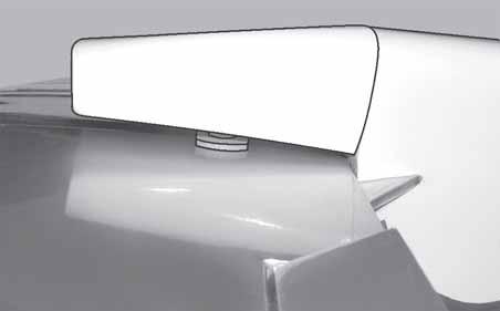
6 MUSTANG P-51. Instruction Manual. Expoxy. Carefully slide the two wing halves together and firmly press them together, allowing the excess epoxy to run out. There should not be any gap in the wing halves. Use rubbing alcohol and a paper tower to clean up any excess epoxy. Remove covering. C/A glue. Apply masking tape at the wing join to hold the wing halves together securely. INSTALLING THE AILERON SERVOS. Servos. Small weight. Masking tape. Thread. We recommended to use long servos arm for all servos without throttle servo. 4) Peel off the backing from the self adhesive covering strip. Apply the strip to the centre section of the wing starting from the bottom trailing edge. Wrap the strip all the way around the wing until it meets the trailing edge again. Trim off any excess strip. Install the rubber grommets and brass collets onto the aileron servo. Test fit the servo into the aileron servo mount. Install the servo into the servo tray. 6


")


7 Because the size of servos differ, you may need to adjust the size of the precut opening in the mount. The notch in the sides of the mount allow the servo lead to pass through. Using a small weight (Weighted fuel pick-up works well) and thread, feed the string through the wing as indicated. Thread. Thread. Small weight. Small weight. Wing bottom. Install the aileron servo tray into the servo mount. Repeat the procedure for orther wing haft. Thread. Small weight. Attach the string to the servo lead and carefully thread it though the wing. Once you have thread the lead throught the wing, remove the string so it can use for the other servo lead. Tape the servo lead to the wing to prevent it from falling back into the wing. Electric wire. Thread. Thread. 7

 Using a ruler & pen to draw a straight line as below picture.")


 Thread one adjustable control horn onto each aileron control rod.")
8 MUSTANG P-51. Instruction Manual. 3) Position the aileron horn on the bottom side of aileron. The clevis attachment holes should be positioned over the hinge line. Control Horn. Plastic tape. Mounting Screws. Mounting Plate. AILERON LINKAGE. INSTALLING THE AILERON LINKAGE. 1) Using a ruler & pen to draw a straight line as below picture. 4) Using a 1mm drill bit and the control horns as a guide, drill the mounting holes through the aileron halves. 5) Mount the control horns by inserting the screws through the control horn bases and aileron halves, then into the mounting backplates. Do not overtighten the screws or the backplates may crush the wood. 6) Thread one adjustable control horn onto each aileron control rod. Thread the horns on until they are flush with the ends of the control rods. Pen. Servo arm. Straigh line. 2) Locate the two nylon control horns, two nylon control horn backplates and two machine screws. 2mm x 20 mm. 8


 Using a modeling knife, remove the")


9 Wing pannel. Aileron. Repeat the procedure for the other aileron servo. Clevis. MAIN LANDING GEAR INSTALLATION. INSTALLING THE MAIN GEAR WIRES. Pen. Aileron torque rod. Cut. 3mm x 10mm. 1) Using a modeling knife, remove the covering from over the two main gear mounting slots located in the bottom of the wing. One slot is located in each wing half. Mounting slot. M2 clevis. M2 lock nut. Snap keeper. Remove covering. 2) Insert the 90º bend of one main gear wire into the predrilled hole in one mounting slot. 3) The landing gear wire is held in place using two nylon landing gear straps and four 3mm x 10mm wood screws. 9
 Slide one wheel collar with 3mm x 6mm set screw onto each axle.")
 Using the two landing gear straps as a guide, mark the locations of the four 3mm x 10mm mounting screws onto the wing surface.")
 Slide one 60mm diameter wheel onto each axle and push them up against the wheel collars.")

 Remove the two straps and the gear wire. Drill four 1mm pilot holes into the wing for the wood screws.")
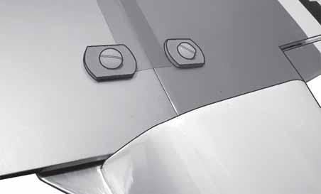
10 MUSTANG P-51. Instruction Manual. The straps should be located equal distance from the inside and outside ends of the wire. INSTALLING THE MAIN GEAR WHEELS. 1) Slide one wheel collar with 3mm x 6mm set screw onto each axle. Push the wheel collars on as far as they will go and tighten the set screws. Landing gear wire. Pen. 4) Using the two landing gear straps as a guide, mark the locations of the four 3mm x 10mm mounting screws onto the wing surface. 1mm screw bit. Be careful not to overtighten the set screws. Overtightening may cause the threads to strip. 2) Slide one 60mm diameter wheel onto each axle and push them up against the wheel collars. Slide the remaining wheel collars with 3mm x 6mm set screws onto the axles. Push them up against the wheels and tighten the set screws. The wheels should spin free and not bind in any way. If they do bind, loosen the set screws in the outer wheel collars and move the collars out a small amount. Retighten the set screws. 5) Remove the two straps and the gear wire. Drill four 1mm pilot holes into the wing for the wood screws. Be careful not to drill through the top of the wing! INSTALLING THE PLASTIC GUN. See pictures below: 3mmX10mm. 6) Reinstall the gear wire and install the straps using the four 3mm x 10mm wood screws. Tighten the screws completely to secure the gear wire in place. Repeat the procedure for the other wing half. 10

 Using a modeling knife, cut one length of silicon fuel line. Connect one end of the line to the weighted fuel pickup and the other end to the nylon pick up tube.")

 With the stopper assembly in place, the weighted pickup should rest away from the rear of the tank and move freely inside the tank.")
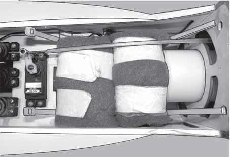
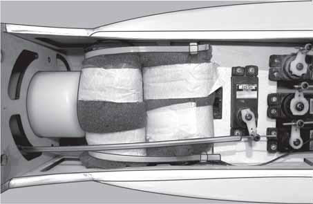
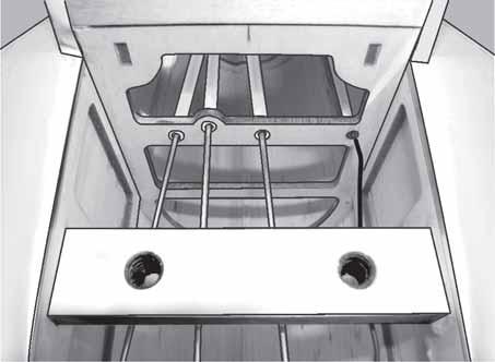
11 C/A glue. Repeat the procedure for the other main gear wheel. FUEL TANK. INSTALLING THE STOPPER ASSEMBLY. Vent tube. Fuel Pickup Tube. Fuel Fill Tube. Carefully use a lighter or heat gun to permenently set the angle of the vent tube. 1) Using a modeling knife, carefully cut off the rear portion of one of the 3 nylon tubes leaving 1/2 protruding from the rear of the stopper. This will be the fuel pick up tube. 2) Using a modeling knife, cut one length of silicon fuel line. Connect one end of the line to the weighted fuel pickup and the other end to the nylon pick up tube. 3) Carefully bend the second nylon tube up at a 45º angle. This tube is the vent tube. Important: When the stopper assembly is installed in the tank, the top of the vent tube should rest just below the top surface of the tank. It should not touch the top of the tank. 4) Test fit the stopper assembly into the tank. It may be necessary to remove some of the flashing around the tank opening using a modeling knife. If flashing is present, make sure none falls into the tank. 5) With the stopper assembly in place, the weighted pickup should rest away from the rear of the tank and move freely inside the tank. The top of the vent tube should rest just below the top of the tank. It should not touch the top of the tank. 6) When satisfied with the alignment of the stopper assembly tighten the 3mm x 20mm machine screw until the rubber stopper expands and seals the tank opening. Do not overtighten the assembly as this could cause the tank to split. 11


 Install the pushrod housing through")

12 MUSTANG P-51. Instruction Manual. Pull. Blow through the tubes to make sure the lines have not become kinked during installation. Cut. Attach the silicone fuel and pressure pipes to the tank. The lower pipe is the feed and the upper two the pressure and fill. The fill pipe is the next pipe. Fuel tank. Vent tube. INSTALLING THE FUEL TANK. Plastic tape. Pushrod wire. Fuel pickup tube. Fuel fill tube. MOUNTING THE ENGINE. 1) Install the pushrod housing through the predrilled hole in the firewall and into the servo compartment. The pushrod housing should protrude 1/4" out past the front of the firewall. Make a Z-Bend 1/4" from one end of the plain wire pushrod. 12
 Place your engine onto the engine mount.")
 When you are satisfied with the alignment, mark the locations")

. 5.5cm.")

 Attach the Z-Bend in the pushrod wire to the throttle arm on")
13 11.2cm. 3mm X 25mm. 2) Place your engine onto the engine mount. Adjust the engine is centered of the edges of the engine case. 3) When you are satisfied with the alignment, mark the locations of the engine mounting. 4) Remove the engine. Using an drill bit, drill the mounting holes through the engine mount at the four locations marked. Pushrod wire. Pen. 3x25mm(4 pcs). 5.5cm. 5) Bolt the engine to the engine mount using the four machine screws. Double cheek that all the screws are tight before proceeding. 6) Attach the Z-Bend in the pushrod wire to the throttle arm on the carburetor. You will need to remove the throttle arm from the carburetor to be able to attach the Z-bend. When complete, reattach the throttle arm to the carburetor. Remove covering 13
 While keeping the back edge of the cowl flush with the marks, align the front of the cowl with")


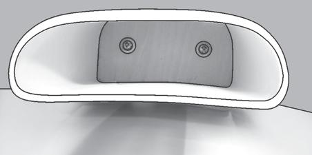
14 MUSTANG P-51. Instruction Manual. 2) While keeping the back edge of the cowl flush with the marks, align the front of the cowl with the crankshaft of the engine. The front of the cowl should be positioned so the crankshaft is in nearly the middle of the cowl opening. Use the spinner backplate as a guide. Hold the cowl firmly in place using pieces of masking tape. Because of the diameter of the cowl, it may be necessary to use a needle valve extension for the high speed needle valve. Make this out of sufficient length 1.5mm wire and install it into the end of the needle valve. Secure the wire in place by tightening the set screw in the side of the needle valve. COWLING. 1) Slide the fiberglass cowl over the engine and line up the back edge of the cowl with the marks you made on the fuselage then trim and cut. Trim and cut. 3) Slide the cowl back over the engine and secure it in place using four 3mm x 10mm wood screws. See picture below. 3mmX10mm. 4) Install the muffler and muffler extension onto the engine and make the cutout in the cowl for muffler clearance. Connect the fuel and pressure lines to the carburetor, muffler and fuel filler valve. Trim and cut. 14
. The propeller should not touch any part of the spinner cone.")
 Install the switch into the precut hole in the servo tray, in the fuselage, from the bottom.")
 Using a 3/32 drill bit, drill a hole through the side of the fuselage, opposite the muffler, even with the switch.")

 Install the rubber grommets and brass collets onto the elevator, rudder and throttle servos. Test fit the servos into the preinstalled servo tray.")
15 Needle valve. 3mmX10mm. Glue attached. INSTALLING THE SPINNER. 1) Install the spinner backplate, propeller and spinner cone. The spinner cone is held in place using two 3mm x 15mm wood screws. (spinner is not included). The propeller should not touch any part of the spinner cone. If it does, use a sharp modeling knife and carefully trim away the spinner cone where the propeller comes in contact with it. INSTALLING THE SWITCH. 1) Install the switch into the precut hole in the servo tray, in the fuselage, from the bottom. Use the two screws provided with the switch to secure it in place. Drill two 3/32 holes through the tray for the screws to pass through. 2) Using a 3/32 drill bit, drill a hole through the side of the fuselage, opposite the muffler, even with the switch. 3) Make a push-pull lever out of scrap wire. Attach the wire to the switch lever and route the wire out the side of the fuselage, through the hole you drilled. Some switches come with a hole drilled through the switch tab for this very purpose. If your switch does not, remove the switch and drill a 3/32 hole through the middle of the switch tab. 3/ 32 Hole. 4 ) Install the rubber grommets and brass collets onto the elevator, rudder and throttle servos. Test fit the servos into the preinstalled servo tray. Because the size of servos differ, you may need to adjust the size of the precut openings in the tray. 5) Position the servos into the servo tray with the output shafts orientated as shown below. Drill 1/16 pilot holes through the tray for each of the mounting screws. 15
 Using a ruler and a pen, locate the centerline of the horizontal")


Using a modeling knife, carefully remove the covering at mounting slot of")

 Slide the stabilizer into place in the precut slot in the rear of the")

16 MUSTANG P-51. Instruction Manual. Switch. HORIZONTAL STABILIZER. 1) Using a ruler and a pen, locate the centerline of the horizontal stabilizer, at the trailing edge, and place a mark. Use a triangle and extend this mark, from back to front, across the top of the stabilizer. Also extend this mark down the back of the trailing edge of the stabilizer. Center line. INSTALLING THE FUSELAGE SERVOS. 2)Using a modeling knife, carefully remove the covering at mounting slot of horizontal stabilizer ( both side of fuselage). Elevator. Rudder. Elevator. Throttle. Switch. Remove covering. Remove covering. Install servos arm to servos. Notice the position of the servos arm on the servos. See picture below. 3) Slide the stabilizer into place in the precut slot in the rear of the fuselage. The stabilizer should be pushed firmly against the front of the slot. 4) With the stabilizer held firmly in place, use a pen and draw lines onto the stabilizer where it and the fuselage sides meet. Do this on both the right and left sides and top and bottom of the stabilizer. 16
 After the epoxy has fully cured, remove the masking tape or T-pins used to hold the stabilizer in place. Carefully inspect the glue joints.")

 When you are sure that everything is aligned correctly, mix up a generous amount of 30 Minute Epoxy.")

17 Pen. 5) Remove the stabilizer. Using the lines you just drew as a guide, carefully remove the covering from between them using a modeling knife. Remove covering. 8) After the epoxy has fully cured, remove the masking tape or T-pins used to hold the stabilizer in place. Carefully inspect the glue joints. Use more epoxy to fill in any gaps that may exist that were not filled previously and clean up the excess using a paper towel and rubbing alcohol. VERTICAL STABILIZER INSTALLATION. When cutting through the covering to remove it, cut with only enough pressure to only cut through the covering itself. Cutting into the balsa structure may weaken it. 6) Using a modeling knife, carefully remove the covering that overlaps the stabilizer mounting platform sides in the fuselage. Remove the covering from both the top and the bottom of the platform sides. 7) When you are sure that everything is aligned correctly, mix up a generous amount of 30 Minute Epoxy. Apply a thin layer to the top and bottom of the stabilizer mounting area and to the stabilizer mounting platform sides in the fuselage. Slide the stabilizer in place and realign. Double check all of your mea surements once more before the epoxy cures. Hold the stabilizer in place with T-pins or masking tape and remove any excess epoxy using a paper towel and rubbing alcohol. 1) Using a modeling knife, carefully remove the covering from over the precut hinge slot cut into the lower rear portion of the fuselage. This slot accepts the lower rudder hinge. Hinge slot. Hinge. 2) Slide the vertical stabilizer into the slot of the fuselage. The bottom edge of the stabilizer should also be firmly pushed against the top of the horizontal stabilizer. 17
 While holding the vertical stabilizer firmly in place, use a pen and draw a line on each side of the vertical stabilizer where it meets the top of the fuselage. Epoxy glue. Pen.")

18 MUSTANG P-51. Instruction Manual. Horizontal Stabilizer. 90º Vertical Stabilizer. 3) While holding the vertical stabilizer firmly in place, use a pen and draw a line on each side of the vertical stabilizer where it meets the top of the fuselage. Epoxy glue. Pen. 4) Remove the stabilizer. Using a modeling knife, remove the covering from below the lines you drew. Also remove the covering from the bottom edge of the stabilizer and the bottom and top edges of the filler block. Leave the covering in place on the sides of the filler block. 6) When you are sure that everything is aligned correctly, mix up a generous amount of 30 Minute Epoxy. Apply a thin layer to the mounting slot in the top of the fuselage and to the sides and bottom of the vertical stabilizer mounting area. Apply epoxy to the bottom and top edges of the filler block and to the lower hinge also. Set the stabilizer in place and realign. Double check all of your measurements once more before the epoxy cures. Hold the stabilizer in place with T-pins or masking tape and remove any excess epoxy using a paper towel and rubbing alcohol. Allow the epoxy to fully cure before proceeding. 7) Turn the fuselage panel over and deflect the vertical stabilizer in the opposite direction from the opposite side. Apply thin C/A glue to hinge, making sure that the C/A penetrates into thevertical stabilizer and fuselage panel. Remove covering. When cutting through the covering to remove it, cut with only enough pressure to only cut through the covering itself. Cutting into the balsa structure may weaken it. 5) Slide the vertical stabilizer back in place. Using a triangle, check to ensure that the vertical stabilizer is aligned 90º to the horizontal stabilizer. 8) Using C/A remover/debonder and a paper towel, remove any excess C/A glue that may have accumulated on the fuselage or in the vertical stabilizer hinge area. Work the rudder left and right several times to work in the hinges and check for proper movement. 18
 Locate the two nylon control horns, two nylon control horn backplates and four machine")

 Using a 1.")


19 Cut. CONTROL HORN INSTALLATION. 1) Locate the two nylon control horns, two nylon control horn backplates and four machine screws. Cut. 2) Position the elevator horn on the both side of elevator. The clevis attach- ment holes should be positioned over the hinge line. 2mmX20mm. Control Horn. Sanding. Mounting Screws. Mounting Plate. Elevator control horn. 3) Using a 1.5mm drill bit and the control horns as a guide, drill the mounting holes through the elevator halves. Rudder control horn. 4) Mount the control horns by inserting the bolts through the control horn bases and elevator halves, then into the mounting backplates. Do not overtighten the nuts or the backplates may crush the wood. Elevator control horn. 5) Position the rudder control horn on the left side of the airplane. Mount the control horn parallel with the horizontal stabilizer. Rudder control horn. 19
 Elevator and rudder pushrods assembly follow pictures below. Switch. Elevator. Pushrod. Control horn. Throttle. Rudder.")

 One at a time, hold the pushrods in position over the respective servos to check for proper servo direction.")
 Set the tail wheel assembly in place on the plywood plate.")
 Using a pen, mark the locations of the two mounting screws.")
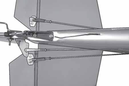
20 MUSTANG P-51. Instruction Manual. ELEVATOR - RUDDER PUSHROD INSTALLATION. 1) Elevator and rudder pushrods assembly follow pictures below. Switch. Elevator. Pushrod. Control horn. Throttle. Rudder. Elevator. M2 lock nut. 2) Connect the elevator and rudder servos to your radio s receiver and turn on the system. Set the trim tabs on the transmitter to neutral and center the servo arms. The elevator and rudder servo arms should be perpendicular to the servos. MOUNTING THE TAIL WHEEL BRACKET. 3mmX12mm. 3) One at a time, hold the pushrods in position over the respective servos to check for proper servo direction. If any servo turns in the wrong direction, switch your radio s reversing switches as necessary to achieve the correct direction. 1) Set the tail wheel assembly in place on the plywood plate. The pivot point of the tail wheel wire should be even with the rudder hinge line and the tail wheel bracket should be centered on the plywood plate. 2) Using a pen, mark the locations of the two mounting screws. Remove the tail wheel bracket and drill 1mm pilot holes at the locations marked. 3) Secure the tail wheel bracket in place using two 3mm x 12mm wood screws. Be careful not to overtighten the screws. 20
 Wrap the receiver and battery pack in the protective foam rubber to protect them from vibration.")


 While holding the clasp firmly in place, use a pen and outline the clasp onto the rudder.")
21 INSTALLING THE RECEIVER AND BATTERY. 1) Plug the six servo leads and the switch lead into the receiver. Plug the battery pack lead into the switch also. 2) Wrap the receiver and battery pack in the protective foam rubber to protect them from vibration. MOUNTING THE CONTROL CLASP. 1) Align the tail wheel wire so that the wire is parallel with the bottom of the rudder. The control clasp has a predrilled hole through the top of it. Slide this hole onto the tail wheel wire while sliding the clasp over the bottom of the rudder. 2) Using a ruler and a pen place a mark onto the bottom of the rudder, in front of the rear edge of the tail wheel wire. The back edge of the clasp should line up with this mark. You may find it necessary to bend the tail wheel wire down slightly so it lines up with the clasp without binding. When balancing the airplane you may need to move the battery or receiver forward or after to achieve proper balance. 3) Route the antenna in the antenna tube inside the fuselage and secure it to the bottom of fuselage using a plastic tape. See picture below. Plywood tray. 3) While holding the clasp firmly in place, use a pen and outline the clasp onto the rudder. 4) Remove the clasp, and using a modeling knife, remove the covering from inside the lines you drew. Use 220 grit sandpaper and carefully roughen the inside surface of the nylon clasp. C/A glue. 5) Slide the clasp back into position and carefully glue it into place using Kwik Bond Thin C/A. Hold the clasp in place until the glue completely cures. Rescue the clap with bolt and nut as picture below. 2mm x 20mm. Control clasp. 21

22 MUSTANG P-51. Instruction Manual. Receiver. ATTACHMENT WING-FUSELAGE. Battery. 4mmX20mm. Oil cooling part. Antenna tube. Antenna. 22
23 BALANCING. 1) It is critical that your airplane be balanced correctly. Improper balance will cause your plane to lose control and crash. The center of gravity is locate 7cm back from the leading edge of the wing, measured at wing tip. 2) If the nose of the plane falls, the plane is nose heavy. To correct this first move the battery pack further back in the fuselage. If this is not possible or does not correct it, stick small amounts of lead weight on the fuselage sides under the horizontal stabilizer. If the tail of the plane falls, the plane is tail heavy. To correct this, move the battery and receiver forward orif this is not possible, stick weight onto the firewall or use a brass heavy hub spinner hub, similar to those offered by Harry Higley. When balanced correctly, the airplane should sit level or slightly nose down when you lift it up with your fingers. INITIAL FLYING/SPORT FLYING Ailerons: 3/16 up 3/16 down Elevator: 5/16 up 5/16 down Rudder: 3/4 right 3/4 left AEROBATIC FLYING Ailerons: 3/8 up 3/8 down Elevator: 5/8 up 5/8 down Rudder: 1-1/4 right 1-1/4 left Do not use the aerobatic settings for initial test flying or sport flying. 4) By moving the position of the adjustable control horn out from the control surface, you will decrease the amount of throw of that control surface. Moving the adjustable control horn toward the control surface will increase the amount of throw. FLIGHT PREPARATION. A) Check the operation and direction of the elevator, rudder, ailerons and throttle. CONTROL THROWS. 1) We highly recommend setting up the MUSTANG P-51 using the control throws listed at right. We have listed control throws for both Low Rate (initial test flying/sport flying) and High Rate (aerobatic flying). 2) Turn on the radio system, and with the trim tabs on the transmitter in neutral, center the control surfaces by making adjustments to the clevises or adjustable servo connectors. The servo arms should be centered also. 3) When the elevator, rudder and aileron control surfaces are centered, use a ruler and check the amount of the control throw in each surface. The control throws should be measured at the widest point of each surface! B) Plug in your radio system per the manufacturer's instructions and turn everything on. C) Check the elevator first. Pull back on the elevator stick. The elevator halves should move up. If it they do not, flip the servo reversing switch on your transmitter to change the direction. D) Check the rudder. Looking from behind the airplane, move the rudder stick to the right. The rudder should move to the right. If it does not, flip the servo reversing switch on your transmitter to change the direction. E) Check the throttle. Moving the throttle stick forward should open the carburetor barrel. If it does not, flip the servo reversing switch on your transmitter to change the direction. F) From behind the airplane, look at the aileron on the right wing half. Move the aileron stick to the right. The right aileron should move up and the other aileron should move down. If it does not, flip the servo reversing switch on your transmitter to change the direction. 23
24 MUSTANG P-51. Instruction Manual. PREFLIGHT CHECK. 1) Completely charge your transmitter and receiver batteries before your first day of flying. 2) Check every bolt and every glue joint in the MUSTANG P-51 to ensure that everything is tight and well bonded. 3) Double check the balance of the airplane. Do this with the fuel tank empty. 4) Check the control surfaces. All should move in the correct direction and not bind in any way. 5) If your radio transmitter is equipped with dual rate switches double check that they are on the low rate setting for your first few flights. 6) Check to ensure the control surfaces are moving the proper amount for both low and high rate settings. 7) Check the receiver antenna. It should be fully extended and not coiled up inside the fuselage. 8) Properly balance the propeller. An out of balance propeller will cause excessive vibration which could lead to engine and/or airframe failure. We wish you many safe and enjoyable flights with your MUSTANG P
INSTRUCTIONS FOR FINAL ASSEMBLY
 MS: 11 INSTRUCTIONS FOR FINAL ASSEMBLY Graphics and specfications may change without notice. Specifications: Wingspan -------------------------------------------- 156 cm, 61.42 in. Wing area ---------------------------------
Instruction Manual book
 Instruction Manual book ITEM CODE BH53. SPECIFICATION Wingspan : 1,250mm 49.21 in. Length : 930mm 36.61in. Weight : 1.1kg 2.42 Lbs. Parts listing required (not included). Battery: 3 CELLS-LI-POLY-11.1V-2,500
INSTRUCTION MANUAL BOOK.
 INSTRUCTION MANUAL BOOK. SPECIFICATION Wingspan : 164 cm 64.57in. Length : 135 cm 53.15 in. Weight : 3.3kg 7.26 lbs. Servo : 7 servos. Radio : 4 channels. Engine : 61 cu.in-2 stroke. 91 cu.in-4 stroke.
Hand-made Almost Ready to Fly R/C Model Aircraft ASSEMBLY MANUAL
 Hand-made Almost Ready to Fly R/C Model Aircraft ASSEMBLY MANUAL Specifications Wingspan -----------------------.148 cm--------------- 58.3 in. Wing area ----------------------- 3474sq. cm ---- 538.4sq
A S S E M B L Y M A N U A L
 A S S E M B L Y M A N U A L Kit features. Ready-made minimal assembly & finishing required. Ready-covered covering. Photo-illustrated step-by-step Assembly Manual. Specifications Wingspan --------------------------
Instruction Manual book
 Instruction Manual book ITEM CODE: BH50. SPECIFICATION Wingspan : 1,600 mm 62.99 in. Length : 1,230 mm 48.43 in. Weight : 2.5 kg 5.5 Lbs. Radio : 06 channels. Servo : 07 servos. Electric Motor : ( 02pcs
Instruction Manual. Specification:
 Instruction Manual H I G Specification: Wingspan: 133 cm (52.3 inches) Length : 104 cm (40.9 inches) Weight : 1830gr Engine : 25-32 two stroke Radio : 4 channel - 4 servo H W I N G KIT CONTENTS: We have
MECOA EZ-4061 Trainer
 MECOA EZ-4061 Trainer EZ-4061 is a newly designed, Almost Ready to Fly kit. It is an extremely easy to control trainer with strong construction and excellent aerodynamic performance. This is a great choice
PERCIVAL P-56 PROVOST
 Instruction Manual Book. PERCIVAL P-56 PROVOST OLEO STRUTS LANDING GEAR. ALL BALSA - PLY WOOD CONSTRUCTION. COVERED WITH ORACOVER Glow and EP 95% ALMOST READY TO FLY SPECIFICATION: - Wingspan: 1,644mm
PROCTOR. Instruction Manual Book 95% ALMOST READY TO FLY. Item code: BH154. SPECIFICATION ALL BALSA - PLY WOOD CONSTRUCTION. COVERED WITH ORACOVER
 Instruction Manual Book PROCTOR Item code: BH154. ALL BALSA - PLY WOOD CONSTRUCTION. COVERED WITH ORACOVER 95% ALMOST READY TO FLY SPECIFICATION Wingspan: 1,360 mm (53.54 in). Length: 1,480 mm(58.27 in).
HAWKER HURRICANE. Instruction Manual Book 95% ALMOST READY TO FLY. Item code: BH147. SPECIFICATION
 Instruction Manual Book Item code: BH147. HAWKER HURRICANE ALL BALSA - PLY WOOD CONSTRUCTION. COVERED IN A HEAT-SHRINK FILM WITH PRINTED. 95% ALMOST READY TO FLY SPECIFICATION Wingspan: 1,520 mm (59.84
NOORDUYN NORSEMAN. Instruction Manual Book 95% ALMOST READY TO FLY. Item code: BH157. SPECIFICATION
 Instruction Manual Book Item code: BH157. NOORDUYN NORSEMAN ALL BALSA - PLY WOOD CONSTRUCTION. COVERED WITH ORACOVER. 95% ALMOST READY TO FLY SPECIFICATION - Wingspan: 1840 mm (72.44 in). - Length: 1180
BUCKER BU 131 JUNGMANN ALL BALSA - PLY WOOD CONSTRUCTION. COVERED WITH ORACOVER
 Instruction Manual Book. BUCKER BU 131 JUNGMANN ALL BALSA - PLY WOOD CONSTRUCTION. COVERED WITH ORACOVER Glow and EP 95% ALMOST READY TO FLY SPECIFICATION: - Wingspan: 1,850 mm (72.83 in). Length: 1,660
Citabria Pro. Aerobatic Parkflyer. by Joel Dirnberger
 Citabria Pro Aerobatic Parkflyer by Joel Dirnberger Revision C: December 21, 2004 Citabria Pro Building Instructions Length: Wingspan: Wing Area: Flying Weight: Wing Loading: Functions: Specifications:
STEP 1 STEP 2 STEP 3. Page 2
 INSTRUCTION MANUAL Congratulations on your purchase of the Bullet ARTF - the first Almost Ready to Fly version of this classic lowwinger. Based on the original and timeless Bullet design, the new Ripmax
TWEETY 25 INSTRUCTION MANUAL. Almost Ready to Fly Nitro/Electric Aerobat FEATURES SPECIFICATIONS
 TWEETY 25 Almost Ready to Fly Nitro/Electric Aerobat INSTRUCTION MANUAL SPECIFICATIONS FEATURES WINGSPAN: 45.7 (1160mm) LENGTH: 38.6 (980mm) WING AREA: 370 sq in(24 sq dm) FLYING WEIGHT: Approx. 3.3 lbs
WE GET PEOPLE FLYING AT-6
 TM WE GET PEOPLE FLYING AT-6 Texan.60 ARF ASSEMBLY MANUAL Specifications Wingspan:... 67.5 in (1714mm) Length:... 48 in (1219mm) Wing Area:... 706 sq in (45.54 sq dm) Weight:... 7 8.5 lb (3.17 3.85 kg)
FUSELAGE CONSTRUCTION
 FUSELAGE CONSTRUCTION Note: prior to building and gluing on the work surface use protective covering on your building surface. (wax paper or clear wrap) Fit the laser cut Fuselage Front and Fuselage Rear
FUJI FA-200 AERO SUBARU
 FUJI FA-200 AERO SUBARU SEMI SCALE SPORT MODEL AERO SUBARU Assembly and Operations Manual Please review this manual throughly Before assembling or Operating The AERO SUBARU Semi scale sport model We ve
FAIREY ALBACORE. Instruction Manual Book. Glow and EP. Item code: BH % ALMOST READY TO FLY SPECIFICATION:
 Instruction Manual Book. FAIREY ALBACORE ALL BALSA - PLY WOOD CONSTRUCTION. COVERED IN A HEAT-SHRINK FILM WITH PRINTED. Glow and EP 95% ALMOST READY TO FLY SPECIFICATION: - Wingspan: 1,693mm (66.65in).
JUNKERS JU87- B2 STUKA
 Instruction Manual Book Item code: BH169. JUNKERS JU87- B2 STUKA OLEO STRUTS LANDING GEAR. ALL BALSA - PLY WOOD CONSTRUCTION. COVERED IN A HEAT-SHRINK FILM WITH PRINTED. 95% ALMOST READY TO FLY SPECIFICATION:
LANDING GEAR. 1. Fit landing gear into slots on bottom of fuselage.
 LANDING GEAR 1. Fit landing gear into slots on bottom of fuselage. 4. Use channel-lock pliers to press blind nuts into position (note: drilled hole should be slightly smaller than shaft of blind nut for
30% Edge 540T Almost Ready to Fly
 Lanier R/C 30% Edge 540T Almost Ready to Fly WARNING! THIS IS NOT A TOY! THIS IS NOT A BEGINNERS AIRPLANE This R/C kit and the model you will build from it is not a toy! It is capable of serious bodily
Instruction Manual. Item No: AL001
 Instruction Manual Item No: AL001 Specifications: Wingspan: 2037mm (80.2 in) Length: 1677mm (66 in) Wing Area: 65.5dm2 (1015.3 sq in) Flying Weight: 7.6kg (16.7 lbs) Engine(not incl.): 45-50cc Gas Radio(not
Super Sky Surfer 2000 Assembly Instructions
 Super Sky Surfer 2000 Assembly Instructions Note: Plug and Play version of the Sky Surfer comes with fuselage pre-glued and motor/servos installed. If you wish to route antennas or wires through the tail,
High performance 90mm fiberglass jet
 High performance 90mm fiberglass jet Assembly manual For intermediate and advanced fliers only! Specs Wingspan: 1255mm Fuselage length: 1250mm Flying weight: 2600-3000g Wing area: 22.6 dm² Wing loading:
(Build Instructions)
") (Build Instructions) Specifications * Wingspan: 58cm * Length: 50cm * Flying Weight: 59 grams * Channels: 3 (Rudder Elevator Throttle) * Suggested Receiver: 4Ch Micro * Motor: 8mm GearDrive * Prop: GWS
(Build Instructions) Specifications * Wingspan: 58cm * Length: 50cm * Flying Weight: 59 grams * Channels: 3 (Rudder Elevator Throttle) * Suggested Receiver: 4Ch Micro * Motor: 8mm GearDrive * Prop: GWS
RYAN STA SAFETY PRECAUTIONS. "Sport Scale E-Power ARF" For Intermediate and Advanced Fliers. This radio control model is not a toy!
 RYAN STA "Sport Scale E-Power ARF" For Intermediate and Advanced Fliers. SAFETY PRECAUTIONS This radio control model is not a toy! First-time builders should seek advice from people with model building
Parts Identification
 We are excited to introduce the Model Aero Aqua Sport. This is an excellent sport flyer, equally at home flying from grass fields, water, or even snow! The unique V-tail gives the Aqua Sport a distinctive
Corvus Racer CC
 Corvus Racer 540 35CC Item No:L-G035008 Specifications Wing Span Length Wing Area Flying Weight Glow Gasoline Electric Radio mm mm 1200sq in (77.4sqdm) 9.9-12lbs(4.5-5.5kg) 91-1.20(2C) 1.10-1.40(4C) 20-40cc
Corvus Racer Colour schemes. AeroPlus RC Copyright 2013 All Rights Reserved
 Corvus Racer 540 59 Item No:A E050003 Specifications WING SPAN: 59"(1500mm) LENGTH: 54.1"(1374mm) WING AREA: 654sq.in.(42.2sq.dm.) FLYING WEIGHT: 4.6 5.3lbs(2000 2300g) Electric:Brushless outrunner 8Oz.
C-180 Builder s Manual
 C-180 Builder s Manual. May 20, 2002 Last revised July 11, 2002 Copyright! 2002 Douglas Binder, Mountain Models www.mountainmodels.com sales@mountainmodels.com (719) 630-3186 1 Required Equipment! Xacto
WE GET PEOPLE FLYING INSTRUCTION MANUAL
 TM WE GET PEOPLE FLYING INSTRUCTION MANUAL 90% prebuilt Giant scale legal Precovered with genuine UltraCote Featuring one-of-a-kind scale trim scheme Prefinished fiberglass cowl Gas or glow option Specifications
ASSEMBLY & OPERATIONS MANUAL
 TM TM AERO SUBARU 40-52 ARF ECS SEMI SCALE MODEL WITH POLYCOTE ECS ENHANCED GRAPHICS SYSTEM #VMA-S140B (blue as shown) #VMA-S140R (red) This model may be produced in a number of different graphic schemes
DORNIER DO 27 SEMI SCALE SPORT MODEL DORNIER DO 27. Please review this manual throughly Before Assembling or Operating The DORNIER DO 27
 DORNIER DO 27 SEMI SCALE SPORT MODEL DORNIER DO 27 Assembly and Operations Manual Please review this manual throughly Before Assembling or Operating The DORNIER DO 27 Semi Scale Sport Model We ve used
Assembly Instructions. Stinger 120. Almost Ready to Fly
 Stinger 120 Almost Ready to Fly Important Information: Please inspect the plane before beginning to assemble to make sure you are happy with it. After assembly has begun you cannot return the kit. If you
INSTRUCTION MANUAL. Suitable for Electric or I.C. Engine Power
 INSTRUCTION MANUAL Suitable for Electric or I.C. Engine Power Congratulations on the purchase of your Irvine Tutor 40 II Radio Control Model Aircraft. Please take some time to carefully read these instructions
PITTS S2S CONSTRUCTION
 PITTS S2S CONSTRUCTION FUSELAGE CONSTRUCTION 1) Place the right fuselage side over the plan and mark the former positions. Place the left side over the right side and mark the former positions. Glue F1
Extra 330LT CC. 2 Colour schemes H-G120001A ORACOVER FERRARI RED # ORACOVER WITH # ORACOVER BLACK # ORACOVER SILVER #
 Extra 330LT 85-125CC Item No:A-G120001 Specs: WING SPAN: LENGTH: WING AREA: FLYING WEIGHT: ENGINE: RADIO: Description Covering Material Carbon Fibre: 111 (2833mm) 100" (2530mm) 2139sq in (138sq dm) 25.3-28lbs
Edge 540 V3 35CC. Scheme A. Item No:L G Specifications. Flying Weight
 Edge 540 V3 35CC Item No:L G035016 Specifications Wing Span Length Wing Area Flying Weight Glow Gasoline Electric Radio Description 76 (1930mm) 74 (1879mm) 1200sq in(77.4sqdm) 9.9 12lbs(4.5 5.5kg) 91 1.20(2C)
Hot Stik ARF WARNING. Copyright 2005 Carl Goldberg Products LTD CARL GOLDBERG PRODUCTS, LTD.
 Hot Stik ARF INSTRUCTIONS WARNING A radio-controlled model is not a toy and is not intended for persons under 16 years old. Keep this kit out of the reach of younger children, as it contains parts that
105" TIGER MOTH ARF INSTRUCTION MANUAL VERSION 1.0
 105" TIGER MOTH ARF INSTRUCTION MANUAL VERSION 1.0 Step 1. Installation of the aileron servos 1) Mount aileron servo to servo mounting blocks with servo s screws. Install servo mounting plate with screws.
RADIO CONTROL MODEL / RC FLUGMODELL INSTRUCTION MANUAL
 RADIO CONTROL MODEL / RC FLUGMODELL INSTRUCTION MANUAL SPECIFITIONS Wingspan...57.5 in. / 146cm Length...50 in. / 127cm Engine...46 2T /.70 4T or Electric equivalent. Radio...4 ~ 6 channel Almost ready
Ryan STA Sport Scale Model Aircraft Assembly and Instruction Manual
 Ryan STA Sport Scale Model Aircraft Assembly and Instruction Manual Warning: This radio controlled model is not a toy. It requires skill to fly and is not recommended for the novice pilot. It should not
RESolution V2 Manual
 RESolution V2 Manual Note for the German Manual: Yellow Bottle thick CA Pink Bottle Med CA Blue tube 5 minute Epoxy Green tube 90 Minute Epoxy Construction of the Fuselage Step 1: Cover the plan with a
EXTRA 330SC 60CC. Item No:H G Specifications cc gas DA50,DA60, DLE55, DLE60(twin), 3W55. Description
, 3W55. Description") EXTRA 330SC 60CC Item No:H G060011 Specifications Wing Span Length Wing Area Flying Weight Gasoline Radio Description Carbon Fibre : 92" (2347mm) 84 1/2 " (2060mm) 1526.8 sq in(98.5sq dm) 16 17lbs(7300
EXTRA 330SC 60CC Item No:H G060011 Specifications Wing Span Length Wing Area Flying Weight Gasoline Radio Description Carbon Fibre : 92" (2347mm) 84 1/2 " (2060mm) 1526.8 sq in(98.5sq dm) 16 17lbs(7300
TIGER MOTH 120 ASSEMBLY INSTRUCTIONS
 TIGER MOTH 120 ASSEMBLY INSTRUCTIONS SPECIFICATIONS Wing Span: Length: Radio: Flying Weight: 1920mm 1580mm 4 channel with 6 servos 4200g AILERON ASSEMBLY 1 Start by removing the servo cover from the bottom
F3A -70E ASSEMBLY MANUAL
 F3A -70E ASSEMBLY MANUAL The new F3A-70E, was designed in an extremely lightweight structure, the all wood airframe, and the new revolutionary Lift Generator on landing gear give the F3A-70E an impressive
Thank you for your purchase of the Lee Ulinger, FoamtanaS, Yak-55, or Extra 330 3D Depron foam, Aerobatic airplane.
 Thank you for your purchase of the Lee Ulinger, FoamtanaS, Yak-55, or Extra 330 3D Depron foam, Aerobatic airplane. Tools you will need to build Recommended additional items: #11 hobby knife Motor: Hacker
Sbach 1,2m 3D/aerobatic EPP model Building instructions
 Sbach 1,2m 3D/aerobatic EPP model Building instructions Please refer to the Diagram sheet Diagrams A, B Press 2 carbon strips (1x3x1000 mm) into the grooves in the sides of the fuselage central part (the
INCLUDED IN THIS KIT: SPECIFICATION: NEEDED BUILDING TOOLS: REQUIRED EQUIPMENT:
 Please review this entire manual before beginning assembly. By doing so it will help you better understand each step as you progress in the actual building of your kit, and you will do a better job in
INSTRUCTIONS FOR FINAL ASSEMBLY. Specifications:
 .60-1.20 Size Sport-Aerobatic A.R.F. INSTRUCTIONS FOR FINAL ASSEMBLY Specifications: The Modeltech Dragon Lady 60 ARF is distributed exclusively by Global Hobby Distributors 18480 Bandilier Circle, Fountain
Assembly Instructions STINGER
 STINGER 120 ARF Important Information: Please inspect the plane before beginning to assemble to make sure you are happy with it. After assembly has begun you cannot return the kit. If you find a problem
INCLUDED IN THIS KIT: SPECIFICATION: NEEDED BUILDING TOOLS: REQUIRED EQUIPMENT:
 Please review this entire manual before beginning assembly. By doing so it will help you better understand each step as you progress in the actual building of your kit, and you will do a better job in
62 AJ Acuity Assembly Instructions
 62 AJ Acuity Assembly Instructions Congratulations The all-new AJ Aircraft Acuity was designed to give you all of the precision flight abilities of expensive composite aircraft, in a more traditional balsa
Cover the wing trailing edge and the aileron leading edge with strapping tape as shown.
 Cover the wing trailing edge and the aileron leading edge with strapping tape as shown. The aileron hinges are done using strapping tape on the top and bottom surfaces of the ailerons as shown. Make sure
DORNIER DO 27 SEMI SCALE SPORT MODEL DORNIER DO 27. Assembly and Operations Manual
 DORNIER DO 27 SEMI SCALE SPORT MODEL DORNIER DO 27 Assembly and Operations Manual Please review this manual throughly Before assembling or Operating The DORNIER DO 27 Semi scale sport model We ve used
LANIER - Double Trouble - INSTRUCTIONS. Tail 1 T1 ¼ Balsa 1 T2 ¼ Balsa 2 T3 ¼ Balsa 1 T4 ¼ Balsa 1 T5 ¼ Balsa 1 T6 ¼ Balsa 2 J1 ¼ Balsa 2 J2 Lite ply
 Tail 1 T1 ¼ Balsa 1 T2 ¼ Balsa 2 T3 ¼ Balsa 1 T4 ¼ Balsa 1 T5 ¼ Balsa 1 T6 ¼ Balsa 2 J1 ¼ Balsa 2 J2 Lite ply Other Parts 2 Aluminum Gear 1 3/32 Music wire tail skid 2 Elevator and J-plane joiner wire
CARL GOLDBERG PRODUCTS, LTD.
 Eagle 400 WARNING A radio-controlled model is not a toy and is not intended for persons under 16 years old. Keep this kit out of the reach of younger children, as it contains parts that could be dangerous.
Zeon PDF Driver Trial
 Mach Dart Slope Soarer Congratulations on your purchase of the Mach Dart Glider. This aircraft was crafted utilizing the latest technology in composite model aircraft design and manufacture. The Dart is
Magpie. Foam Trainer. Magpie Specifications
 Magpie Foam Trainer Magpie Specifications Length: 34in. Wingspan (SF): 46in. Wing Area (SF): 414in 2 Wingspan (SP): 40in. Wing Area (SP): 360in 2 Weight (without battery): 12oz. Thank you for purchasing
Building Tips This model can be built using the following types of adhesives:
 Page 1 Building Tips This model can be built using the following types of adhesives: Epoxy (with or without microballons) Odorless cyanoacrylate (CA) with accelerator UHU Creativ for Styrofoam (or UHU
MXS R 30CC. Item No:L G Specifications. 67 1/2"(1720mm) (2C) (4C) 26 35cc gas DLE 30/35RA MLD35 JC30Evo.
 (2C) (4C) 26 35cc gas DLE 30/35RA MLD35 JC30Evo.") MXS R 30CC Item No:L G030008 Specifications Wing Span Length Wing Area Flying Weight Glow Gasoline Electric Radio Description Covering Material Carbon Fibre : 75"(1915mm) 67 1/2"(1720mm) 1023sq in(66sq
MXS R 30CC Item No:L G030008 Specifications Wing Span Length Wing Area Flying Weight Glow Gasoline Electric Radio Description Covering Material Carbon Fibre : 75"(1915mm) 67 1/2"(1720mm) 1023sq in(66sq
TIGER SHARK-40 ARF ASSEMBLY MANUAL
 TIGER SHARK-40 ARF ASSEMBLY MANUAL Kangke Industrial USA, Inc. 65 East Jefryn Blvd. Deer Park NY 11729 http://www.kangkeusa.com E-mail: info@kangkeusa.com Tel: 1-877-203-2377 Fax: 1-631-274-3296 Congratulations!
67 Edge 540 ARF WARNING
 67 Edge 540 ARF INSTRUCTIONS WARNING A radio-controlled model is not a toy and is not intended for persons under 16 years old. Keep this kit out of the reach of younger children, as it contains parts that
SPUNKY ASSEMBLY MANUAL
 SPUNKY ASSEMBLY MANUAL Please read the tips section at the back of this manual regarding the use of laser cut parts. The proper removal and preparation of these parts is important. When laser cut, some
AT channel 6 servos
 Wing Span: Wing Area: Fuselage Length: Flying weight: Power system: Radio: 60.7in/1540mm 561 sq in/36.3 sq dm 44.1in/1120mm 6.9 Ibs/ 3100g 46(2C0/71(4C) 5 channel 6 servos AT6-46 INSTALLING AILERONS Begin
94 Yak 54 ARF WARNING
 94 Yak 54 ARF WARNING A radio-controlled model is not a toy and is not intended for persons under 16 years old. Keep this kit out of the reach of younger children, as it contains parts that could be dangerous.
S.E.5a (Build Instructions)
") S.E.5a (Build Instructions) Specifications Wingspan: 38 cm Length: 31cm Flying Weight: 41 Channels: 3 (Rudder Elevator Throttle) Suggested Receiver: 3Ch Brick Motor: 7mm Geared Motor Airframe Only Kit
S.E.5a (Build Instructions) Specifications Wingspan: 38 cm Length: 31cm Flying Weight: 41 Channels: 3 (Rudder Elevator Throttle) Suggested Receiver: 3Ch Brick Motor: 7mm Geared Motor Airframe Only Kit
Assembly Manual / Airframe 65 Vyper SAFETY in Assembly SAFETY in Flying
 1 Assembly Manual / Airframe 65 Vyper Thank you for purchasing this 3DHobbyShop ARF RC aircraft. If you have any issues, questions, concerns or problems during assembly, please contact our tech department
CARL GOLDBERG PRODUCTS, LTD.
 Chipmunk 400 WARNING A radio-controlled model is not a toy and is not intended for persons under 16 years old. Keep this kit out of the reach of younger children, as it contains parts that could be dangerous.
10 th Anniversary 51 AJ Slick 540 Assembly Instructions
 10 th Anniversary 51 AJ Slick 540 Assembly Instructions Up Your Game! Fly AJ Aircraft From all of us at AJ Aircraft, we thank you for your business. Our custom designs, combined with top grade materials,
87 Extra 330 ARF WARNING
 87 Extra 330 ARF WARNING A radio-controlled model is not a toy and is not intended for persons under 16 years old. Keep this kit out of the reach of younger children, as it contains parts that could be
HIGH-END TECHNOLOGY. Electric ducted fan Starfighter
 HIGH-END TECHNOLOGY RC Electric ducted fan Starfighter First we want to thank and congratulate you with your decision in buying one of our Kits. The Starfighter puts together very easily so there is not
FLITZEBOGEN-2 Assembly instructions
 FLITZEBOGEN-2 Assembly instructions Trim the end of the fuselage to the length of 925mm from the nose. Be careful to avoid splitting the carbon fibers. Sand the base of the stab mount in preparation for
Admas A500. Specification:
 Admas A500 Specification: Length :07 mm(8.7") Wing Span :00 mm(9.5") Wing Area :8.8 sq. dm 5.5 sq. ft Wing Loading :3 g/sq. dm 53.7 oz/sq. ft Flying Weight :8 kg(7.lbs) Radio :ch &3 servos Engine : -cycle
Specifications Wingspan: 80-1/8" Wing Area: 850 sq. in. Weight (Approx.): lbs. Recommended Engines: Cycle.45-.
: lbs. Recommended Engines: Cycle.45-.") TM WE GET PEOPLE FLYING ASSEMBLY MANUAL Specifications Wingspan: 80-1/8" Wing Area: 850 sq. in. Weight (Approx.): 6.5-7.0 lbs. Recommended Engines:.40-.46 2-Cycle.45-.60 4-Cycle Raising the Standard of
TM WE GET PEOPLE FLYING ASSEMBLY MANUAL Specifications Wingspan: 80-1/8" Wing Area: 850 sq. in. Weight (Approx.): 6.5-7.0 lbs. Recommended Engines:.40-.46 2-Cycle.45-.60 4-Cycle Raising the Standard of
Specifications Wingspan: 43cm Flying Weight: 33 grams (with battery) Channels: 3 Suggested Receiver: 4Ch Micro Motor: 7mm Brushed Geardrive
 Channels: 3 Suggested Receiver: 4Ch Micro Motor: 7mm Brushed Geardrive") Specifications Wingspan: 43cm Flying Weight: 33 grams (with battery) Channels: 3 Suggested Receiver: 4Ch Micro Motor: 7mm Brushed Geardrive Airframe Kit (Included Contents) * Airframe Parts Sheets (Depron)
Specifications Wingspan: 43cm Flying Weight: 33 grams (with battery) Channels: 3 Suggested Receiver: 4Ch Micro Motor: 7mm Brushed Geardrive Airframe Kit (Included Contents) * Airframe Parts Sheets (Depron)
ParkJet Builder s Manual
 ParkJet Builder s Manual Thank you for purchasing the ParkJet. The ParkJet is a profile ducted fan airplane that can be flown in a larger park. The ParkJet was initially designed by Scott Stoops and modified
Sig Mfg. Co., Inc South Front Street...Montezuma, Iowa 50171
 Sig Mfg. Co., Inc...401-7 South Front Street...Montezuma, Iowa 50171 Introduction The SEALANE takes off and lands on water just as easy as the Sig Kadet LT40 does on solid ground. Gentle, graceful, sure
77 Edge 540 ARF WARNING
 77 Edge 540 ARF INSTRUCTIONS WARNING A radio-controlled model is not a toy and is not intended for persons under 16 years old. Keep this kit out of the reach of younger children, as it contains parts that
Dandy Sport Builder s Manual
 Dandy Sport Builder s Manual Thank you for purchasing the Dandy Sport. The Dandy Sport has been designed as an easy to build aileron trainer. Take your time and enjoy building this plane. Specifications:
43in EPP Acrocub Instruction Manual
 43in EPP Acrocub Instruction Manual Specifications Wingspan: 43.3in (1100mm) Length: 41.3in (1050mm) Flying Weight: Approx. 1.5lb (670g) Dear Customer, Congratulations on your purchase of 43in EPP Acrocub
35 Magnum. Instruction Manual
 EPP EPP 35 35 Magnum Rebel Z Instruction Manual This is how your kit will arrive When cutting the hardware package open use caution. The contents are semi-coiled to fit in the box. They will spring open
56 & 60 AJ Laser 230z Assembly Instructions
 56 & 60 AJ Laser 230z Assembly Instructions Congratulations Whether you're looking to go out and go 3d huckin' or lay down a smooth-as-butter precision flight, the 56 or 60 Laser 230z is for you! The wings
F - 4u Corsair (50cc)
") F - u Corsair (50cc) Specification: Length: 73(.3") Wing span: 0mm(5") Wing area: 7.00sq.dm(9.39sq.ft) Wing loading: 35.g/sq.dm(.5oz/sq.ft) Flying weight:.kg(.0lbs) Radio: ch & 0servos Engine: 50cc gasoline
F - u Corsair (50cc) Specification: Length: 73(.3") Wing span: 0mm(5") Wing area: 7.00sq.dm(9.39sq.ft) Wing loading: 35.g/sq.dm(.5oz/sq.ft) Flying weight:.kg(.0lbs) Radio: ch & 0servos Engine: 50cc gasoline
L 410 UVP-E Turbolet. Recommended equipment and guide for the building of RC model aircraft.
 L 410 UVP-E Turbolet Recommended equipment and guide for the building of RC model aircraft. - 1 - History of L-410 It has been 45 years since the first small commercial L-410 prototype took off. The first
ALBATROSS by CRASHTESTHOBBY.COM
 ALBATROSS by CRASHTESTHOBBY.COM The Albatross is a unique slow flyer designed to put its nose on the horizon and level its own wings without a pilot. It is very quiet and designed to use inexpensive electronics.
Hawker hurricane MK.IIa
 Hawker hurricane MK.IIa Specification: Length :00 mm(") Wing Span :00 mm(") Wing Area :0. sq. dm.9 sq. ft Wing Loading :.9 g/sq. dm 5.9 oz/sq. ft Flying Weight :.kg(5 lbs) Radio :ch& servos Engine :0 INSTRUCTION
B-25 Mitchell INSTRUCTION MANUAL SAFETY PRECAUTIONS
 B-5 Mitchell Specification: Length :935 mm(76.") Wing Span :0 mm(95") Wing Area :77.6 sq. dm 7./sq.ft Wing Loading : g/sq. dm oz/sq. ft Flying Weight :0 kg(. lbs) Radio :6ch&3 servos Engine(a pair) :9
LANIER - Ultimate Pitts - INSTRUCTIONS. Additional Parts Required. (12) 4-40 blind nuts (Dubro #606)
 4-40 blind nuts (Dubro #606)") Additional Parts Required (4) or more channel radio with 7-8 servos..91-2.2 two stroke or 1.20-1.84 four stroke engine Appropriate Master Airscrew prop and Hayes mount for your engine. 3 Tru-Turn spinner
Additional Parts Required (4) or more channel radio with 7-8 servos..91-2.2 two stroke or 1.20-1.84 four stroke engine Appropriate Master Airscrew prop and Hayes mount for your engine. 3 Tru-Turn spinner
Switchback Sport Builder s Manual
 Switchback Sport Builder s Manual Thank you for purchasing the Switchback Sport. The Switchback Sport has been designed for the novice to intermediate pilot who wants a plane with good performance that
uin RC FPRC ZERO Specificationss Empty Weight
 Flying Pengu uin RC FPRC ZERO Specificationss Wing Span 42.75 (1085 mm) Fuselage length 30.5 ( 775 mm) Empty Weight 9.5 10 oz. (150 160g) Estimated Flying Weight 20 255 oz. (320 400g) Wing Area: 151 sq.
SebArt professional line
 SebArt professional line Wind S 110 ARF ASSEMBLY MANUAL The new Wind S 110 ARF was designed by Italy aerobatic pilot, Sebastiano Silvestri. This professional ARTF kit is the result of Sebastiano s 20 years
E-AERO EPP PITTS KIT From BP HOBBIES. Parts Included in kit
 E-AERO EPP PITTS KIT From BP HOBBIES Parts Included in kit Thank you for purchasing the BP Hobbies/E-aero EPP Pitts. Please take the time to read through the instruction manual before beginning the build.
CARL GOLDBERG PRODUCTS, LTD.
 Pitts Monster Aerobatic flying just doesn't get any better than this Pitts ARF. The classic lines of a biplane coupled with the radial cowl, add excitement to the maneuvers you love, knife edge, split
Building Instructions. Scarlet RC model aircraft. Order No. 1308/00. Specification: approx mm. rudder, flaps, throttle.
 Building Instructions RC model aircraft Order No. 1308/00 Specification: Wingspan Length Wing area All-up weight Wing loading RC functions approx. 3000 mm approx. 1270 mm approx. 53.5 dm² approx. 1.45
Taylorcraft Indoor / Cul-De-Sac Flyer
 Taylorcraft Indoor / Cul-De-Sac Flyer Taylocraft Specifications Wingspan: 28.0 in. Wing Area: 117 sq. in. Weight (Ready to Fly): 3.0 3.1 oz. Wing Loading: 3.7 3.8 oz. / sq. ft. LIABILITY RELEASE In that
P-47D Thunderbolt. Two wheel retract system Make sure to assemble retracts as instructed below. 3-way pressure inlet INSTRUCTION MANUAL
 70 Adjustment. 7 The centre of the Gravity. Side View AILERON FLAP 0mm 0mm P-7D Thunderbolt AILERON FLAP 0mm 3mm Two wheel retract system Make sure to assemble retracts as instructed below. 3-way pressure
Aviator Trainer40 ARF Instruction Manual Specifications
 Aviator Trainer40 ARF Instruction Manual Specifications Wingspan: 65.0 in (1650 mm) Length: 53.1 in (1350 mm) Wing Area: 729sq in (47.0 sq dm) Flying Weight: 5.3 lbs (2400g) Dear Customer, Congratulations