62 AJ Acuity Assembly Instructions
|
|
|
- Nickolas Doyle
- 5 years ago
- Views:
Transcription

1 62 AJ Acuity Assembly Instructions
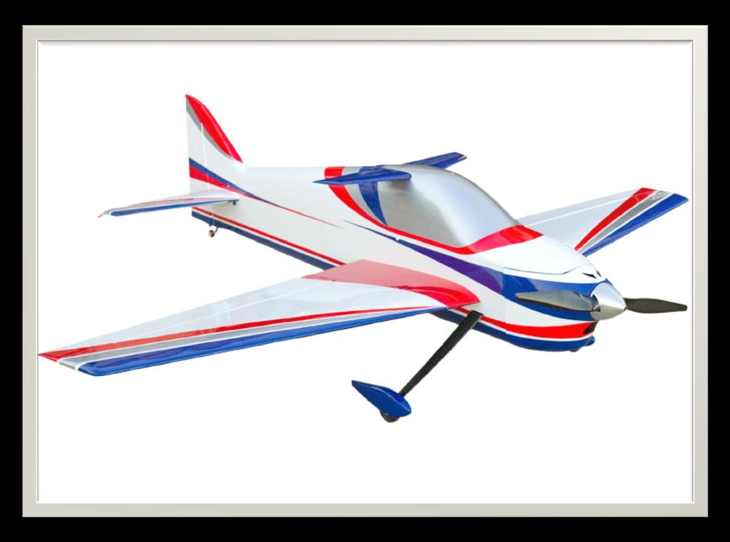
2 Congratulations The all-new AJ Aircraft Acuity was designed to give you all of the precision flight abilities of expensive composite aircraft, in a more traditional balsa & plywood frame. Designed by our own F3A pattern champion Andrew Jesky, this 62" model will be a perfect introduction to competition pattern aerobatics. With a tall & slender fuselage, slim swept wing and T-Canaliser on the canopy, the Acuity will slip perfectly through any aerobatic maneuver. And the suggested electronics setup will work perfectly with the 5&6s mAh packs you likely already own. Up Your Game! Fly AJ Aircraft AJ Aircraft thanks you for the purchase of this airplane. Top grade materials and precision assembly have been used to make this a top quality aircraft. Following the directions closely, will assure you many hours of thrilling flight. Two years of design, development and testing has gone into this airframe. We hope you re as happy with it as we are! WARNING! AJ Aircraft s extensive testing ensures a high quality kit that has gone through many stages to provide you with a safe, reliable, airframe. Poor assembly will lead to an unsafe model and therefore the instructions must be followed closely. Should you have any questions, please do not hesitate to contact us. The safe operation of this model is your responsibility and yours alone. If you are a beginner or have never flown a model of this size and power you should attempt it with the help of an experienced pilot. This product should not be considered a toy, but rather a sophisticated, working model that functions much like a full-scale airplane. Because of its performance capabilities, this product, if not assembled and operated correctly, could cause injury to you or spectators and damage to property. This aircraft should be flown in accordance to the AMA safety code. It is highly recommended that you join the Academy of Model Aeronautics in order to be properly insured and to operate your model at AMA sanctioned flying fields. If you are not willing to accept all liability for the use of this product please return if to the place of purchase immediately. AJ Aircraft does not accept responsibility or liability for damages resulting from use of this product. Before starting, read through the entire set of instructions to familiarize yourself with the process. Additional assembly information can be found in assembly videos on the AJ-Aircraft YouTube Channel If there s ever a question, contact AJ Aircraft aj-aircraft.com Page 1
3 Contents Congratulations... 1 Contents... 2 Features... 2 Optional Configurations... 3 Recommended Items for Completion... 3 Tools Needed... 3 Covering... 4 Wings... 4 Landing Gear... 9 Fuselage Elevator Rudder Push-Pull Rudder Control Pull-Pull Rudder Control Electric Motor Cowl & Canopy Radio Installation & Setup Features Specs: Wing Span - 62" Length - 60" AUW (dry) lb Electric Power Watt Motor 90amp ESC 5-6s mah LiPo Radio - 5 Channel 3 Mini High Torque Servos 1 Standard Size High Torque Servo What's in the box: 62 Acuity Airframe Fiberglass Cowl & Wheel Pants Carbon reinforced landing gear mount Pre-hinged and sealed control surfaces Removable rudder Carbon main gear G-10 control horns Dual ball links for all connections Carbon wing tube Foil Wing bags Light weight foam wheels Complete hardware package Genuine Ultracote Covering aj-aircraft.com Page 2
4 Optional Configurations You have the option of using a pull-pull rudder servo or a push-pull rudder servo setup. Fasteners, control horns and servo connecting rods are provided for optional rudder setups. Recommended Items for Completion Hacker A50-12s Falcon 16x10 prop Castle 90 ESC Thunder Power 5s 5000mah LiPo Futaba BLS1053/BLS551 Servos on Elevator/Rudder Futaba S9670SV Servos on Ailerons (4) x 6" Servo Extensions for the Ailerons and Rx to Wing (1) x 12" Servo Extension for the ESC to Receiver (1) x 36" Servo Extension for the Elevator (6) Servo Connector Safety Clips 2.75" or 70mm Spinner Tools Needed Blue Painter s Masking Tape Thin CA Glue 30 Minute Epoxy Denatured Alcohol Paper Towels Removable Thread Locker (Loctite 242, Blue) Metric & Imperial Allen Wrenches Hobby Knife & Fresh Blades Covering Iron (Trim Iron) Clamps Small Flat File Electric Drill w/ Assorted Small Bits (1/16, 5/64 ) Small Flat Blade Screwdrivers Small Phillips Screwdriver Sandpaper ( Grit) Pliers Measuring Tape & Ruler aj-aircraft.com Page 3


 At 200-220 F (93-104 C) the adhesive on UltraCote becomes active allowing the covering to be attached to the model.")
5 Covering The covering on your Laser may have developed loose areas through temperature and humidity changes between manufacturing and shipping. This may also occur during the summer heat. The covering may require retightening a few times during your first summer of flying. Take a few minutes to go over all of the seams making sure all edges are secure. Then proceed to shrinking any area that may need tightening. (Use an iron on all seams. Use a heat gun on open areas and sheeted areas. An iron can be used in open and sheeted areas but hold the iron slightly above the surface. You don t want press the covering into the wood. Using an iron sock will reduce scratches. Genuine Ultracote covering. (White HANU870, True Red HANU866, Midnight Blue HANU885, Silver HANU881) At F ( C) the adhesive on UltraCote becomes active allowing the covering to be attached to the model. While 220 will fully bond the covering to the model it is well below the temperature that causes UltraCote to shrink. At 300 F (149 C) the initial shrinking of UltraCote begins. At 350 F (176 C) UltraCote reaches its maximum shrinking point. Raising the temperature above this point will not cause further shrinkage. Use as little heat as needed. Using too much heat may cause reshrinking issues later. Wings Carefully locate the aileron servo pocket. Shining a light through opposite side of the wing will help highlight the pocket location. Use a new hobby knife blade to cut though the covering. Cut from the corners of the pocket towards the center of the pocket so the covering can be folded in. Use an iron to seal around the servo pocket. Fold the cut covering under the wing sheeting and attach it to the inside edge of the pocket. Gently snap off the servo wire installation string (if it s attached) and temporarily secure it out of the way. Do not pull it out of the wing! aj-aircraft.com Page 4


 Notice how the hinges may pull out slightly.")

6 Carefully locate the aileron control horn slots. Use a covering iron to bond the covering in the area the control horn will sit. Trim the covering away to expose the slots. Be sure not to cut through to the top side covering. Slip each of the aileron hinges into the wing. Align the end of the aileron to the wing tip. The hinges should already be glued into the ailerons. Give each of them a little pull to ensure they are securely attached. It s better to find a loose hinge now rather than during a flight. Push the aileron tight against the wing closing the gap between the two of them. Move the aileron to its maximum desired deflection. (About 15 ) Notice how the hinges may pull out slightly. Experiment with the hinge position finding the best fit before gluing. The wings are already slotted for the hinges. Use a covering iron to secure the covering along the edge of the wings and ailerons. Look at the wing hinge slots closely. Make sure the covering will not interfere when gluing the hinges. Cut away any covering that covers the hinge slot. Apply a piece of tape next to each hinge. This will help you locate the hinges when you begin gluing them. aj-aircraft.com Page 5


7 Check the aileron position at the hinges and wing tip again before gluing. Start with the hinge near the wing tip. Flex the aileron slightly and apply a few drops of thin CA glue to one side. Flex the aileron to its maximum desired position. Then glue the opposite side. Use sand paper to roughen the lower portion of the control horns on both sides. This will help the epoxy bond to the control horn parts. Test fit the control horn in the slot. Trim or file the slot as needed to achieve a snug fit. Close the gap between the aileron and wing to the desired position at the fuselage end of the wing half. Flex the aileron slightly and apply a few drops of thin CA glue to both sides of the hinge. Again move the aileron back and forth to check its position. Once the end hinges are securely positioned you can apply a few drops of thin CA to both sides of the remaining hinges. The control horn should go in all the way in until the shoulder contacts the aileron. The linkage hole in the control horn should be aligned with the hinge centerline. Use the control horns from the Wings part bag. With the control horn in position apply masking tape around it. This will help keep excess epoxy off the covering. aj-aircraft.com Page 6


8 Apply epoxy to the slot in the aileron. Use a pin to help push the epoxy in. Connect the servo to a receiver and power supply. Turn on your transmitter. Set trim and sub trim to zero. Install a servo arm on the servo about perpendicular to the servo s side. Use the transmitter s sub trim to make it exactly perpendicular to the side of the servo. Apply epoxy to the control horn and insert it into the slot. Wipe away excess epoxy using a paper towel and denatured alcohol. Attach a servo extension and a safety clip to the servo. Check the alignment along the hinge line as you did when you test fit the control horn. Reposition as needed. Attach the servo wire to the installation string and gently pull the wire through the wing as you insert the servo into the wing. Allow the epoxy to partially cure. Peel away the masking tape after the epoxy is securely holding the control horn in place and still soft enough to easily remove the tape. Set the wing aside and let the epoxy fully cure. aj-aircraft.com Page 7


 Check the length of the assembly to the servo with the aileron level with the wing.")
 Reinstall the servo.")
9 With the servo installed mark the mounting hole locations. Pre-drill for servo mounting screws using a 1/16 drill. Install the servo with the wood screws that came with your servos. Remove the screws and servo. Apply a drop of thin CA glue into each mounting screw hole. This will harden the wood around the screws and provide a more secure installation. (Allow the CA glue to dry before reinstalling the servo.) Check the length of the assembly to the servo with the aileron level with the wing. Once the correct length of the assembly is found connect the servo arm to the servo. (Always adjust the connecting rod length with the servo powered up and centered.) Reinstall the servo. Assemble a ball link to each end of a connecting rod. Connect a ball link to a servo horn and the aileron control horn. Use a socket head screw, a flat washer and a nylon lock nut. (The brass ball in the link is offset. The larger reveal side should be against the control horn as shown below.) aj-aircraft.com Page 8


10 Landing Gear Landing gear parts bag contents are shown below. Slip the landing gear through the slot. Notice that there are right and left hand parts. The landing gear should be swept back. The landing gear screws are supplied installed in the fuselage. Remove these screws. Use 4 flat washers from the parts bag with the screws removed earlier to attach the landing gear. Add a drop of removable thread locker to the screws during assembly. Carefully locate the landing gear slot in the side of the fuselage just below the leading edge of the wing pocket. Use a covering iron to attach the covering around the slot. Make a single cut in the center of the slot the width of the landing gear. (A magnet makes installing the screw much easier.) aj-aircraft.com Page 9


11 File a flat on the wheel axels perpendicular to the axel wrench flats. Predrill a 5/64 hole into the wheel pant then add a wood screw to secure the wheel pants. Install a wheel on the axel with a wheel collar. Position the collar set screw over the flat you filed. Install the tail wheel after the rudder installation. Install the tailwheel using 3 wood screws. Position the joint of the tail wheel assembly directly over the rudder hinge line and mark the position of the screws. Turn the screws into the fuselage and rudder. Remove the screws, add a drop of thin CA glue to each hole to strengthen the wood, and reinstall the screws. (Do not fully tighten the tiller arm screw. The slot in the tiller arm allows the screw move accounting for any misalignment between the assembly & rudder.) (You may prefer to install the wheels and wheel pants later as a final assembly step. They may get in the way when handling the fuselage during assembly.) Insert the wheel and axel into the wheel pant, then into landing gear. Align the wheel pant indentation with the landing gear. Add a nylon lock nut and tighten. aj-aircraft.com Page 10


. The front pocket will be used for the elevator servo.")
12 Fuselage Inspect the fuselage for any interior joints that may have loosened as a result of shipping & handling. Apply thin CA glue as needed. Apply thin CA glue around the joints of the fuselage core, firewall, fuselage formers, and rudder servo tray to strengthen. Carefully locate the horizontal stabilizer pocket. Use an iron to seal the covering around the edges of the pocket before trimming. Use a new hobby knife blade to cut though the covering. Review the servo configurations as described on page 3 before cutting the covering over the servo pockets. There are 2 servo pockets below the horizontal stabilizer slot on both sides of the fuselage (highlighted with tape). The front pocket will be used for the elevator servo. The pocket near the tail of the fuselage on the opposite side will be for a rudder servo if you decide to use the pushpull configuration. aj-aircraft.com Page 11


13 Use an iron to seal the covering around the edges of the pocket before cutting. Cut the covering then fold it into the pocket and attach it with an iron. If you choose to use a push-pull rudder servo cut open the back pocket on the opposite side. Position the stabilizer perpendicular to the fuselage and parallel to the main wing tube. Measure the distance between the canopy latch and the corners of the horizontal stabilizer. Adjust the stabilizer until the measurements on both sides are equal. Continue checking the stabilizer to ensure it is still centered side to side as described above. Extra time spent here will go a long way to improve the flight characteristics of your airplane. Slide the horizontal stabilizer through the fuselage pushing it all the way forward. Center it side to side using a ruler or tape measure. Install and center the main wing tube. Look at the plane from the back forward to make sure that the horizontal stabilizer is parallel with the wing tube. Notice that the horizontal stabilizer is tapered which may obscure the actual alignment. If the stabilizer is not aligned use shims or sand inside the pocket until it s parallel. Once the horizontal stabilizer is positioned glue it in place with thin CA glue. Wick glue in on left and right sides, top and bottom. The use of an applicator tip is suggested to control the flow of thin CA glue and get it exactly where you want it. aj-aircraft.com Page 12


 Use a covering iron to bond the covering in the area the control horn will sit. Trim the covering away to expose the slot.")

14 Use a covering iron to attach the covering around the opening in the bottom of the fuselage. Use a new hobby knife blade to cut the covering from the opening. Glue with 30 minute epoxy. Remove masing tape. Roughen up the jointer plate for the elevator halves with sand paper so the epoxy will adhere better. Elevator The elevator hinges should already be glued in. Give each of them a little pull to ensure they are securely attached. The jointer plate between the elevator halves is also already glued into one half of the elevator. Test fit the elevator joiner plate to the opposite elevator half. Ensure the elevator halves are not twisted. Adjust the slot in the elevator as needed. Install a control horn in the elevator using the same procedure used when assembling the ailerons. (If you cut open the servo pocket in the left of the fuselage make sure you are working with the left elevator half.) Use a covering iron to bond the covering in the area the control horn will sit. Trim the covering away to expose the slot. Sand the lower portion of the control horn. Test fit the control horn. The shoulder contacts the elevator and the linkage hole should be aligned with the hinge centerline. Mask around slot. Glue in the elevator halves using a similar procedure as the aileron assembly. The horizontal stabilizer is already slotted for the hinges. Use a covering iron to secure the covering along the edge of the stabilizer and the elevator. Look at the stabilizer hinge slots closely. Make sure the covering will not interfere when gluing the hinges. Cut away any covering that covers the hinge slots. aj-aircraft.com Page 13

 Notice how the hinges may pull out slightly.")


15 Test fit the elevator to the horizontal stabilizer. Mask areas around the jointer plate to prevent excess epoxy getting where you don t want it. Align the end of the elevator to the end of the stabilizer. Push the elevator tight against the stabilizer closing the gap. Move the elevator to its maximum desired deflection. (About 15 ) Notice how the hinges may pull out slightly. Experiment with the hinge position finding the best fit before gluing. Apply a piece of tape next to each hinge to identify its location. Remove the right elevator and glue the left elevator in position first. Check the elevator position at the hinges and wing tip. Flex the elevator slightly and apply a few drops of thin CA glue to the first hinge. Flex the elevator and recheck its position. Add a few drops of CA glue to the third hinge and flex the elevator and check its position. Add a few drops of CA glue to the center hinge and then add CA glue to all 3 hinges on the opposite both sides. Prepare some 30 minute epxoy and apply it to the jointer plate slot in the right elevator half. Slip the elevator half into position and align the end of the elevator to the end of the stabilizer. Begin applying CA glue as you did with the left elevator half. Wipe away excess epoxy and remove masking tape. Clamp the elevator halves in position as shown with 2 sticks and 2 clamps. Set aside to allow epoxy to cure. aj-aircraft.com Page 14


16 Install the elevator servo using the same procedure used when assembling the ailerons. Connect the servo to a receiver and power supply. Turn on your transmitter. Set trim and sub trim to zero. Install a servo arm on the servo about perpendicular to the servo s side. Use the transmitter s sub trim to make it exactly perpendicular to the side of the servo. Assemble a ball link to each end of a connecting rod. Connect a ball link to a servo horn and the elevator control horn. Use a socket head screw, a flat washer and a nylon lock nut. Check the length of the assembly to the servo arm with the elevator level with the stabilizer. Once the correct length of the assembly is found connect it to the servo arm using the provided machine screws washer and lock nut. (Turn on the transmitter, receiver and servo while making adjusting to the connecting rod. This will keep the servo in its correct position.) Attach a servo extension onto the elevator servo lead and use a safety clip to secure the connection. Install the servo into the fuselage and pre-drill for servo mounting screws using a 1/16 drill. Install the servo with the wood screws that came with your servos. Remove the screws and servo. Apply a drop of thin CA glue into each mounting screw hole. This will harden the wood around the screws and provide a more secure installation. (Allow the CA glue to dry before reinstalling the servo.) aj-aircraft.com Page 15


17 Rudder The rudder control can be configured as a push-pull system or as a pull-pull cable system. See the configuration options listed on page 3. Push-Pull Rudder Control The rudder is built with control horn slots for the pushpull control system and the pull-pull control system. The blue masking tape indicates the control horn locations. The push-pull control horn slots are located near the bottom of the rudder. Pull-Pull Rudder Control The rudder is built with control horn slots for the pushpull control system and the pull-pull control system. The blue masking tape indicates the control horn locations. The pull-pull control horn slots are located higher up on the rudder. Cut the rudder covering to expose the control horn slots on both sides of the rudder. The pictures below shows a mockup of the rudder pushpull system. The installation process of the servo and control horn is the same as the ailerons and the elevator. Use sand paper to roughen up the center of the control horn so the epoxy will adhere better. The pull-pull cables can be removed and the covering will need to be patched with covering. aj-aircraft.com Page 16


 Notice how the hinges may pull out slightly. Experiment with the hinge position finding the best fit before gluing.")

18 Tests fit the control horn to the slot. Use a file to modify the slot as needed. Center it side to side and align the holes with the hinge line. The control horn should be symmetrical about the hinge line. The vertical stabilizer is already slotted for the hinges. Use a covering iron to secure the covering along the edge of the rudder and stabilizer. Look at the vertical stabilizer hinge slots closely. Make sure the covering will not interfere when gluing the hinges. Cut away any covering that covers the hinge slot. Slip each rudder hinges into a slot. Align the end of the rudder with the top of the vertical stabilizer. Push the rudder tight against the stabilizer closing the gap between the two of them. Move the rudder to its maximum desired deflection. (About 15 ) Notice how the hinges may pull out slightly. Experiment with the hinge position finding the best fit before gluing. Apply masking tape around the control horn slot on both sides of the rudder. Use 30 minute epoxy to glue the control horns in place. Check the alignment, peal the masking tape away, and clean up with alcohol. Check the alignment again and set aside for the epoxy to cure. (When setting aside to dry position the rudder and control horn so gravity does not reposition the control horn for you.) The hinges should already be glued into the rudder. Give each of them a little pull to ensure they are securely attached. Apply a piece of tape next to each hinge. This will help you locate the hinges when you begin gluing them. Start with the top hinge. Flex the rudder slightly and apply a few drops of thin CA glue to one side. Flex the rudder to its maximum desired position. Then glue the opposite side. aj-aircraft.com Page 17


19 Close the gap to the desired position. Flex the rudder slightly and apply a few drops of thin CA glue the bottom hinge. Again move the rudder back and forth to check its position. Once the end hinges are securely positioned you can apply a few drops of thin CA glue to both sides of the center hinge. Tread the brass cable eyes about half way into the ball links. Start the cable assembly at the servo end inside the fuselage. Thread on 2 crush sleeves and the brass cable eye. Connect the servo to a receiver and power supply. Turn on your transmitter. Set trim and sub trim to zero. Install a servo arm on the servo about perpendicular to the servo s side. Use the transmitter s sub trim to make it exactly perpendicular to the side of the servo. Loop around the cable eye and go back through a crush sleeve. Install the rudder servo into the fuselage and pre-drill for servo mounting screws using a 1/16 drill. Install the servo with the wood screws that came with your servos. Remove the screws and servo. Apply a drop of thin CA glue into each mounting screw hole. This will harden the wood around the screws and provide a more secure installation. (Allow the CA glue to dry before reinstalling the servo.) Loop around the crush sleeve and back through the sleeve again. Slide the second sleeve over the tail. Adjust the loops and crimp the sleeves with the nonserrated surface of standard plyers. aj-aircraft.com Page 18
 between holes.")
 Center the rudder in position aligned to the vertical stabilizer.")

20 Pull the slack out of the cables and make sure the cables cross once inside the fuselage. Connect the ball links to the rudder control horn at 1.77 (45mm) between holes. (A 45mm hole spacing matches the rudder control horn.) Center the rudder in position aligned to the vertical stabilizer. Clamp a couple of balsa sticks across the rudder hinge to keep it centered. Repeat the cable eye installation process on the rudder end of the cables with the servo powered up and centered. Pull the cable snug. You don t need to make the cable guitar string tight. Remove the clamps and adjust the cable lengths to center the rudder by turning the cable eyes into the ball links. aj-aircraft.com Page 19
.")
 from the firewall.")


 away from the firewall.")

21 Electric Motor The firewall is pre-assembled with thread inserts installed on a 58mm diameter bolt circle (41mm X 41mm sq). Use removable thread locker when installing the motor bolts. The cowl length is 4 5/16 (109.5mm) from the firewall. Use nylon zip ties or a hook & loop strap to secure the ESC to the bottom of the motor box. We recommend putting a small piece of foam between the ESC and motor box to dampen vibrations. Use the supplied motor standoff the mount your motor s prop backer plate at least (111mm) away from the firewall. (If you need to shorten the supplied standoffs make sure they all end up the same length so you do not introduce changes to the motor thrust angle.) Place hook & loop tape to the battery tray and the battery. Loop hook & loop straps around the battery. aj-aircraft.com Page 20


 Tape the cowl on in its final position.")
22 Cowl & Canopy Install the canopy on to the fuselage. The cowl will be mounted using 4 wood screws through 4 holes in the side of the fuselage just in front of the firewall. Position the cowl onto the fuselage. Place tape over the holes and past the front of the firewall. Use a pin to poke though the tape and covering locating the mounting hole. Peal the tape back away from each hole but leave it attached to the fuselage. Align the motor shaft with the center of the cowl. (Use the spinner s back plate to help you center the cowl.) Tape the cowl on in its final position. Transfer the hole in the tape to the cowl with a pin. Use a 1/16 drill bit to enlarge the hole in the cowl. Use 4 wood screws through these holes to mount the cowl. aj-aircraft.com Page 21


23 Assemble the T-Canaliser to the canopy using a machine screw and washer in the back hole. Finish the assembly by installing the T-Canaliser cover with 2 more machine screws. You may eliminate the T-Canaliser by installing the supplied filler plate instead. aj-aircraft.com Page 22


24 Radio Installation & Setup Take the time to properly balance and trim your aircraft. Use the suggested throws below as your starting point then fine tune to your flying preferences after your first few flights. Your receiver can be mounted anywhere in the airframe. In front of the wing tube works well on this fuselage. A piece of foam rubber should be used between the fuselage and the receiver to dampen any vibration. Control Throws Elevator 10 Up 13 Down Aileron 12 Up 12 Down Rudder 15 Left 15 Right You can adjust your CG depending on your flying style. If you enjoy sport & precision aerobatics you ll want a slightly nose heavy CG. To test the CG fly left or right at about 3/4 to full throttle and pull to a 45 degree up-line. Roll inverted and let go of the elevator stick. A correct nose heavy CG will slowly arc to the level. A neutral CG should nearly hold the upline. And a tail heavy CG will steepen the up-line. While the final setup is of personal preference, these are some general guidelines to make your first flight a success. The center of gravity is located 7/16 (11mm) to 7/8 (22mm) behind the wing tube. Enjoy your new plane! We at AJ Aircraft sincerely hope you enjoy flying the 62 AJ Acuity. Feel free to create a support ticket at aj-aircraft.com if you have any problems, questions, or suggestions. Once you get a few flights in, we would greatly appreciate your review submitted to our web site! See you at the field! AJ Aircraft 2410 N Monroe St Monroe, MI USA Phone: aj-aircraft.com Page 23 Manual Rev 1..03/17
56 & 60 AJ Laser 230z Assembly Instructions
 56 & 60 AJ Laser 230z Assembly Instructions Congratulations Whether you're looking to go out and go 3d huckin' or lay down a smooth-as-butter precision flight, the 56 or 60 Laser 230z is for you! The wings
10 th Anniversary 51 AJ Slick 540 Assembly Instructions
 10 th Anniversary 51 AJ Slick 540 Assembly Instructions Up Your Game! Fly AJ Aircraft From all of us at AJ Aircraft, we thank you for your business. Our custom designs, combined with top grade materials,
Extra 330LT CC. 2 Colour schemes H-G120001A ORACOVER FERRARI RED # ORACOVER WITH # ORACOVER BLACK # ORACOVER SILVER #
 Extra 330LT 85-125CC Item No:A-G120001 Specs: WING SPAN: LENGTH: WING AREA: FLYING WEIGHT: ENGINE: RADIO: Description Covering Material Carbon Fibre: 111 (2833mm) 100" (2530mm) 2139sq in (138sq dm) 25.3-28lbs
Assembly Manual / Airframe 65 Vyper SAFETY in Assembly SAFETY in Flying
 1 Assembly Manual / Airframe 65 Vyper Thank you for purchasing this 3DHobbyShop ARF RC aircraft. If you have any issues, questions, concerns or problems during assembly, please contact our tech department
EXTRA 330SC 60CC. Item No:H G Specifications cc gas DA50,DA60, DLE55, DLE60(twin), 3W55. Description
, 3W55. Description") EXTRA 330SC 60CC Item No:H G060011 Specifications Wing Span Length Wing Area Flying Weight Gasoline Radio Description Carbon Fibre : 92" (2347mm) 84 1/2 " (2060mm) 1526.8 sq in(98.5sq dm) 16 17lbs(7300
EXTRA 330SC 60CC Item No:H G060011 Specifications Wing Span Length Wing Area Flying Weight Gasoline Radio Description Carbon Fibre : 92" (2347mm) 84 1/2 " (2060mm) 1526.8 sq in(98.5sq dm) 16 17lbs(7300
Corvus Racer Colour schemes. AeroPlus RC Copyright 2013 All Rights Reserved
 Corvus Racer 540 59 Item No:A E050003 Specifications WING SPAN: 59"(1500mm) LENGTH: 54.1"(1374mm) WING AREA: 654sq.in.(42.2sq.dm.) FLYING WEIGHT: 4.6 5.3lbs(2000 2300g) Electric:Brushless outrunner 8Oz.
Citabria Pro. Aerobatic Parkflyer. by Joel Dirnberger
 Citabria Pro Aerobatic Parkflyer by Joel Dirnberger Revision C: December 21, 2004 Citabria Pro Building Instructions Length: Wingspan: Wing Area: Flying Weight: Wing Loading: Functions: Specifications:
Assembly Instructions
 Congratulations AJ Aircra thanks you for the purchase of this airplane. Top grade materials and precision assembly has gone into this to make this a top quality aircra. Following the direcons closely,
RYAN STA SAFETY PRECAUTIONS. "Sport Scale E-Power ARF" For Intermediate and Advanced Fliers. This radio control model is not a toy!
 RYAN STA "Sport Scale E-Power ARF" For Intermediate and Advanced Fliers. SAFETY PRECAUTIONS This radio control model is not a toy! First-time builders should seek advice from people with model building
LANDING GEAR. 1. Fit landing gear into slots on bottom of fuselage.
 LANDING GEAR 1. Fit landing gear into slots on bottom of fuselage. 4. Use channel-lock pliers to press blind nuts into position (note: drilled hole should be slightly smaller than shaft of blind nut for
25mm EPP SU31. Instruction Manual. Specifications
 25mm EPP SU31 Instruction Manual Specifications Wingspan: 39.4in (1000mm) Length: 42in (1070mm) Wing Area: 448sq in (28.9sq dm) Flying Weight: Approx. 1.5lb (650-710g) Dear Customer, www.valuehobby.com/su31-epp.html
F3A -70E ASSEMBLY MANUAL
 F3A -70E ASSEMBLY MANUAL The new F3A-70E, was designed in an extremely lightweight structure, the all wood airframe, and the new revolutionary Lift Generator on landing gear give the F3A-70E an impressive
Corvus Racer CC
 Corvus Racer 540 35CC Item No:L-G035008 Specifications Wing Span Length Wing Area Flying Weight Glow Gasoline Electric Radio mm mm 1200sq in (77.4sqdm) 9.9-12lbs(4.5-5.5kg) 91-1.20(2C) 1.10-1.40(4C) 20-40cc
43in EPP Acrocub Instruction Manual
 43in EPP Acrocub Instruction Manual Specifications Wingspan: 43.3in (1100mm) Length: 41.3in (1050mm) Flying Weight: Approx. 1.5lb (670g) Dear Customer, Congratulations on your purchase of 43in EPP Acrocub
Edge 540 V3 35CC. Scheme A. Item No:L G Specifications. Flying Weight
 Edge 540 V3 35CC Item No:L G035016 Specifications Wing Span Length Wing Area Flying Weight Glow Gasoline Electric Radio Description 76 (1930mm) 74 (1879mm) 1200sq in(77.4sqdm) 9.9 12lbs(4.5 5.5kg) 91 1.20(2C)
Super Sky Surfer 2000 Assembly Instructions
 Super Sky Surfer 2000 Assembly Instructions Note: Plug and Play version of the Sky Surfer comes with fuselage pre-glued and motor/servos installed. If you wish to route antennas or wires through the tail,
Sbach 1,2m 3D/aerobatic EPP model Building instructions
 Sbach 1,2m 3D/aerobatic EPP model Building instructions Please refer to the Diagram sheet Diagrams A, B Press 2 carbon strips (1x3x1000 mm) into the grooves in the sides of the fuselage central part (the
28in Super EVA Foam. F-22 Raptor Kit. Specifications. Wingspan: 27.5in (700mm) Length: 38.3in (975mm) Flying Weight: Approx. 1.
 Length: 38.3in (975mm) Flying Weight: Approx. 1.") 28in Super EVA Foam F-22 Raptor Kit Specifications Wingspan: 27.5in (700mm) Length: 38.3in (975mm) Flying Weight: Approx. 1.2lbs (530g) Dear Customer, Congratulations on your purchase of 28in F22 Raptor
28in Super EVA Foam F-22 Raptor Kit Specifications Wingspan: 27.5in (700mm) Length: 38.3in (975mm) Flying Weight: Approx. 1.2lbs (530g) Dear Customer, Congratulations on your purchase of 28in F22 Raptor
INCLUDED IN THIS KIT: SPECIFICATION: NEEDED BUILDING TOOLS: REQUIRED EQUIPMENT:
 Please review this entire manual before beginning assembly. By doing so it will help you better understand each step as you progress in the actual building of your kit, and you will do a better job in
This pictorial document contains assembly recommendations including some fit and finish details that will be helpful when building this airplane
 This pictorial document contains assembly recommendations including some fit and finish details that will be helpful when building this airplane Problems found with this kit and a flight performance review
Instruction Manual book
 Instruction Manual book ITEM CODE BH53. SPECIFICATION Wingspan : 1,250mm 49.21 in. Length : 930mm 36.61in. Weight : 1.1kg 2.42 Lbs. Parts listing required (not included). Battery: 3 CELLS-LI-POLY-11.1V-2,500
84 Turbo Bushmaster. Copyright 2016 Extreme Flight
 84 Turbo Bushmaster Copyright 2016 Extreme Flight 1 Please take a few moments to read this instruction manual before beginning assembly. We have outlined a fast, clear and easy method to assemble this
Instruction Manual. Item No: AL001
 Instruction Manual Item No: AL001 Specifications: Wingspan: 2037mm (80.2 in) Length: 1677mm (66 in) Wing Area: 65.5dm2 (1015.3 sq in) Flying Weight: 7.6kg (16.7 lbs) Engine(not incl.): 45-50cc Gas Radio(not
INCLUDED IN THIS KIT: SPECIFICATION: NEEDED BUILDING TOOLS: REQUIRED EQUIPMENT:
 Please review this entire manual before beginning assembly. By doing so it will help you better understand each step as you progress in the actual building of your kit, and you will do a better job in
FUSELAGE CONSTRUCTION
 FUSELAGE CONSTRUCTION Note: prior to building and gluing on the work surface use protective covering on your building surface. (wax paper or clear wrap) Fit the laser cut Fuselage Front and Fuselage Rear
Instruction Manual. Specification:
 Instruction Manual H I G Specification: Wingspan: 133 cm (52.3 inches) Length : 104 cm (40.9 inches) Weight : 1830gr Engine : 25-32 two stroke Radio : 4 channel - 4 servo H W I N G KIT CONTENTS: We have
SebArt professional line
 SebArt professional line Wind S 110 ARF ASSEMBLY MANUAL The new Wind S 110 ARF was designed by Italy aerobatic pilot, Sebastiano Silvestri. This professional ARTF kit is the result of Sebastiano s 20 years
Thank you for your purchase of the Lee Ulinger, FoamtanaS, Yak-55, or Extra 330 3D Depron foam, Aerobatic airplane.
 Thank you for your purchase of the Lee Ulinger, FoamtanaS, Yak-55, or Extra 330 3D Depron foam, Aerobatic airplane. Tools you will need to build Recommended additional items: #11 hobby knife Motor: Hacker
MECOA EZ-4061 Trainer
 MECOA EZ-4061 Trainer EZ-4061 is a newly designed, Almost Ready to Fly kit. It is an extremely easy to control trainer with strong construction and excellent aerodynamic performance. This is a great choice
High performance 90mm fiberglass jet
 High performance 90mm fiberglass jet Assembly manual For intermediate and advanced fliers only! Specs Wingspan: 1255mm Fuselage length: 1250mm Flying weight: 2600-3000g Wing area: 22.6 dm² Wing loading:
TWEETY 25 INSTRUCTION MANUAL. Almost Ready to Fly Nitro/Electric Aerobat FEATURES SPECIFICATIONS
 TWEETY 25 Almost Ready to Fly Nitro/Electric Aerobat INSTRUCTION MANUAL SPECIFICATIONS FEATURES WINGSPAN: 45.7 (1160mm) LENGTH: 38.6 (980mm) WING AREA: 370 sq in(24 sq dm) FLYING WEIGHT: Approx. 3.3 lbs
Parts Identification
 We are excited to introduce the Model Aero Aqua Sport. This is an excellent sport flyer, equally at home flying from grass fields, water, or even snow! The unique V-tail gives the Aqua Sport a distinctive
1/6 PA-25 PAWNEE. *Specifications are subject to change without notice.*
 1/6 PA-25 PAWNEE INSTRUCTION MANUAL [ A335 Kit ] Wing Span : 72 in / 1830 mm Wing Area : 736 sq in / 47.5 sq dm Flying Weight : 6.6 lbs / 3000 g Fuselage Length : 48 in / 1220 mm Requires : "Glow Power"
3DHobbyShop.com Edge Assembly Manual
 3DHobbyShop.com Edge 540 92 Assembly Manual Thank you for purchasing this 3DHobbyShop ARF RC aircraft. If you have any issues, questions, concerns or problems during assembly, please contact our tech department
FLITZEBOGEN-2 Assembly instructions
 FLITZEBOGEN-2 Assembly instructions Trim the end of the fuselage to the length of 925mm from the nose. Be careful to avoid splitting the carbon fibers. Sand the base of the stab mount in preparation for
Thunder Tiger Ace Hobby Page 1 6/8/10
 TOC 35% Katana Assembly Manual Thunder Tiger Ace Hobby Page 1 6/8/10 Table of contents Thunder Tiger Contact Information Page 3 Introduction.Page 4 Kit Contents.Page 5 Items Needed to Complete...Page 6
(Build Instructions)
") (Build Instructions) Specifications * Wingspan: 58cm * Length: 50cm * Flying Weight: 59 grams * Channels: 3 (Rudder Elevator Throttle) * Suggested Receiver: 4Ch Micro * Motor: 8mm GearDrive * Prop: GWS
(Build Instructions) Specifications * Wingspan: 58cm * Length: 50cm * Flying Weight: 59 grams * Channels: 3 (Rudder Elevator Throttle) * Suggested Receiver: 4Ch Micro * Motor: 8mm GearDrive * Prop: GWS
Assembly Manual / Airframe 70 Velox
 Assembly Manual / Airframe 70 Velox Thank you for purchasing this 3DHobbyShop ARF RC aircraft. If you have any issues, questions, concerns or problems during assembly, please contact our tech department
MXS R 30CC. Item No:L G Specifications. 67 1/2"(1720mm) (2C) (4C) 26 35cc gas DLE 30/35RA MLD35 JC30Evo.
 (2C) (4C) 26 35cc gas DLE 30/35RA MLD35 JC30Evo.") MXS R 30CC Item No:L G030008 Specifications Wing Span Length Wing Area Flying Weight Glow Gasoline Electric Radio Description Covering Material Carbon Fibre : 75"(1915mm) 67 1/2"(1720mm) 1023sq in(66sq
MXS R 30CC Item No:L G030008 Specifications Wing Span Length Wing Area Flying Weight Glow Gasoline Electric Radio Description Covering Material Carbon Fibre : 75"(1915mm) 67 1/2"(1720mm) 1023sq in(66sq
C-180 Builder s Manual
 C-180 Builder s Manual. May 20, 2002 Last revised July 11, 2002 Copyright! 2002 Douglas Binder, Mountain Models www.mountainmodels.com sales@mountainmodels.com (719) 630-3186 1 Required Equipment! Xacto
35 Magnum. Instruction Manual
 EPP EPP 35 35 Magnum Rebel Z Instruction Manual This is how your kit will arrive When cutting the hardware package open use caution. The contents are semi-coiled to fit in the box. They will spring open
CARL GOLDBERG PRODUCTS, LTD.
 Eagle 400 WARNING A radio-controlled model is not a toy and is not intended for persons under 16 years old. Keep this kit out of the reach of younger children, as it contains parts that could be dangerous.
uin RC FPRC ZERO Specificationss Empty Weight
 Flying Pengu uin RC FPRC ZERO Specificationss Wing Span 42.75 (1085 mm) Fuselage length 30.5 ( 775 mm) Empty Weight 9.5 10 oz. (150 160g) Estimated Flying Weight 20 255 oz. (320 400g) Wing Area: 151 sq.
EPP Rebel Z 35. White Red w/ Blue Orange w/ Blue Orange w/burgundy Other. Specs. Color - Bottom White Black Checkers Silver Checkers Other Checkers
 EPP Rebel Z 35 Specs AUW ~10.0oz Width 35.28 Length 34.67 Wing Area 1.44 sqft Horz Area 2.35 sqft Vert Area.91 sqft
Stream NXT - assembly instructions
 Stream NXT - assembly instructions Recommended settings CG (measured from root leading edge): Speed/launch camber (+down, near the wing root): Cruise camber (+down, near the wing root): Thermal camber
PITTS S2S CONSTRUCTION
 PITTS S2S CONSTRUCTION FUSELAGE CONSTRUCTION 1) Place the right fuselage side over the plan and mark the former positions. Place the left side over the right side and mark the former positions. Glue F1
30% Edge 540T Almost Ready to Fly
 Lanier R/C 30% Edge 540T Almost Ready to Fly WARNING! THIS IS NOT A TOY! THIS IS NOT A BEGINNERS AIRPLANE This R/C kit and the model you will build from it is not a toy! It is capable of serious bodily
Aviator Trainer40 ARF Instruction Manual Specifications
 Aviator Trainer40 ARF Instruction Manual Specifications Wingspan: 65.0 in (1650 mm) Length: 53.1 in (1350 mm) Wing Area: 729sq in (47.0 sq dm) Flying Weight: 5.3 lbs (2400g) Dear Customer, Congratulations
Ryan STA Sport Scale Model Aircraft Assembly and Instruction Manual
 Ryan STA Sport Scale Model Aircraft Assembly and Instruction Manual Warning: This radio controlled model is not a toy. It requires skill to fly and is not recommended for the novice pilot. It should not
CARL GOLDBERG PRODUCTS, LTD.
 Chipmunk 400 WARNING A radio-controlled model is not a toy and is not intended for persons under 16 years old. Keep this kit out of the reach of younger children, as it contains parts that could be dangerous.
TWEETY Instruction Manual. Almost-Ready-to-Fly Nitro/Electric Aerobatic Airplane SPECIFICATIONS FEATURES
 TWEETY - 40 Almost-Ready-to-Fly Nitro/Electric Aerobatic Airplane Instruction Manual SPECIFICATIONS WINGSPAN: 60.1in (1526mm) LENGTH: 46.5in (1180mm) WING AREA: 654 sq in (42.2 sq dm) FLYING WEIGHT: 5.5
E-AERO EPP PITTS KIT From BP HOBBIES. Parts Included in kit
 E-AERO EPP PITTS KIT From BP HOBBIES Parts Included in kit Thank you for purchasing the BP Hobbies/E-aero EPP Pitts. Please take the time to read through the instruction manual before beginning the build.
87 Extra 330 ARF WARNING
 87 Extra 330 ARF WARNING A radio-controlled model is not a toy and is not intended for persons under 16 years old. Keep this kit out of the reach of younger children, as it contains parts that could be
HIGH-END TECHNOLOGY. Electric ducted fan Starfighter
 HIGH-END TECHNOLOGY RC Electric ducted fan Starfighter First we want to thank and congratulate you with your decision in buying one of our Kits. The Starfighter puts together very easily so there is not
Cover the wing trailing edge and the aileron leading edge with strapping tape as shown.
 Cover the wing trailing edge and the aileron leading edge with strapping tape as shown. The aileron hinges are done using strapping tape on the top and bottom surfaces of the ailerons as shown. Make sure
Zeon PDF Driver Trial
 Mach Dart Slope Soarer Congratulations on your purchase of the Mach Dart Glider. This aircraft was crafted utilizing the latest technology in composite model aircraft design and manufacture. The Dart is
Hand-made Almost Ready to Fly R/C Model Aircraft ASSEMBLY MANUAL
 Hand-made Almost Ready to Fly R/C Model Aircraft ASSEMBLY MANUAL Specifications Wingspan -----------------------.148 cm--------------- 58.3 in. Wing area ----------------------- 3474sq. cm ---- 538.4sq
RESolution V2 Manual
 RESolution V2 Manual Note for the German Manual: Yellow Bottle thick CA Pink Bottle Med CA Blue tube 5 minute Epoxy Green tube 90 Minute Epoxy Construction of the Fuselage Step 1: Cover the plan with a
94 Yak 54 ARF WARNING
 94 Yak 54 ARF WARNING A radio-controlled model is not a toy and is not intended for persons under 16 years old. Keep this kit out of the reach of younger children, as it contains parts that could be dangerous.
AT channel 6 servos
 Wing Span: Wing Area: Fuselage Length: Flying weight: Power system: Radio: 60.7in/1540mm 561 sq in/36.3 sq dm 44.1in/1120mm 6.9 Ibs/ 3100g 46(2C0/71(4C) 5 channel 6 servos AT6-46 INSTALLING AILERONS Begin
INSTRUCTIONS FOR FINAL ASSEMBLY
 MS: 11 INSTRUCTIONS FOR FINAL ASSEMBLY Graphics and specfications may change without notice. Specifications: Wingspan -------------------------------------------- 156 cm, 61.42 in. Wing area ---------------------------------
TIGER MOTH 120 ASSEMBLY INSTRUCTIONS
 TIGER MOTH 120 ASSEMBLY INSTRUCTIONS SPECIFICATIONS Wing Span: Length: Radio: Flying Weight: 1920mm 1580mm 4 channel with 6 servos 4200g AILERON ASSEMBLY 1 Start by removing the servo cover from the bottom
INSTRUCTION MANUAL BOOK.
 INSTRUCTION MANUAL BOOK. SPECIFICATION Wingspan : 164 cm 64.57in. Length : 135 cm 53.15 in. Weight : 3.3kg 7.26 lbs. Servo : 7 servos. Radio : 4 channels. Engine : 61 cu.in-2 stroke. 91 cu.in-4 stroke.
Hot Stik ARF WARNING. Copyright 2005 Carl Goldberg Products LTD CARL GOLDBERG PRODUCTS, LTD.
 Hot Stik ARF INSTRUCTIONS WARNING A radio-controlled model is not a toy and is not intended for persons under 16 years old. Keep this kit out of the reach of younger children, as it contains parts that
MUSTANG P-51. Hand-made Almost Ready to Fly R/C Model Aircraft ASSEMBLY MANUAL
 MUSTANG P-51 Hand-made Almost Ready to Fly R/C Model Aircraft ASSEMBLY MANUAL Specifications Wingspan---------------------------------------- 60.5 in----------------------- 153.7cm. Wing area-------------------------------------
Magpie. Foam Trainer. Magpie Specifications
 Magpie Foam Trainer Magpie Specifications Length: 34in. Wingspan (SF): 46in. Wing Area (SF): 414in 2 Wingspan (SP): 40in. Wing Area (SP): 360in 2 Weight (without battery): 12oz. Thank you for purchasing
78" EXTRA 300 ARF. Instruction Manual. Copyright 2009 Extreme Flight RC
 78" EXTRA 300 ARF Instruction Manual Copyright 2009 Extreme Flight RC Please take a few moments to read this instruction manual before beginning assembly. We have outlined a fast, clear and easy method
Assembly Instructions. Stinger 120. Almost Ready to Fly
 Stinger 120 Almost Ready to Fly Important Information: Please inspect the plane before beginning to assemble to make sure you are happy with it. After assembly has begun you cannot return the kit. If you
FUJI FA-200 AERO SUBARU
 FUJI FA-200 AERO SUBARU SEMI SCALE SPORT MODEL AERO SUBARU Assembly and Operations Manual Please review this manual throughly Before assembling or Operating The AERO SUBARU Semi scale sport model We ve
SwitchBack Senior. SwitchBack Senior Specifications
 SwitchBack Senior SwitchBack Senior Specifications Wingspan: 55.4 in. Length: 41 in. Wing Area: 597 sq. in. Weight (Ready to Fly): 34 to 37 oz. Wing Loading: 8.2 to 8.9 oz. / sq. ft. Version 1.05, March
ULS Cherokee. Ultra Low Speed aircraft for indoor RC flying. Zippkits. Specifications: Required to complete:
 Zippkits ULS Cherokee Ultra Low Speed aircraft for indoor RC flying. Specifications: Span- 28 inches Wing Area- 151 Sq/In Wing Loading- 3.0 ounces/ft Weight- 3.5 ounces RTF Build time- 1-2 Hours Radio-
Revolution 3D-mini ARF
 Revolution 3D-mini ARF 1 Included Hardware 4 Dubro Micro Control Horns #DUB848 2.32 x 18" Linkage Wire (Music Wire) 1 1.5 x 1.25 x 1/8 Balsa Ply (for motor mount) 1 5" piece of Velcro (Optional recommended,
SGTalon s Enterprise-A Foamie Build Guide. SGTalon s. Enterprise. Enterprise--A. Assembly Instructions
 SGTalon s Enterprise SGTalon s Enterprise--A Enterprise Assembly Instructions Page 1 4-13-2013 SGTalon s Enterprise *******Recommended Hardware******** 2.6oz 250w Motor and Speed Control with 8x6 prop
White Red w/ Blue Orange w/ Blue Burgundy w/ Orange Other
 Specs AUW ~6.5oz Width 32.875 Length 29.50 Wing Area 1.35 sqft Horz Area 2.22 sqft Vert Area 1.26 sqft Suggested Hardware ~25g 90 watt Motor 12 amp ESC Servos 6g+ (4) 2s LiPo (300-500mAh) 4ch Radio/Rx
Taylorcraft Indoor / Cul-De-Sac Flyer
 Taylorcraft Indoor / Cul-De-Sac Flyer Taylocraft Specifications Wingspan: 28.0 in. Wing Area: 117 sq. in. Weight (Ready to Fly): 3.0 3.1 oz. Wing Loading: 3.7 3.8 oz. / sq. ft. LIABILITY RELEASE In that
INS TRUC T I ON M A NU A L
 INS TRUC T I ON M A NU A L Packing list: 1: PP F6F fuselage *1 2: Carbon tube 5*5*940mm *1 3: Pull rod *4 4: Motor mount *1 5: Quick rod adjuster *4 6: Hinge *4 7: M3 screws *4 8: Hook and loop tape *1
Millennium RC presents The New and Improved (now even easier to build and cover!) SSX X-Trainer Build Kit
 SSX X-Trainer Build Kit") Millennium RC presents The New and Improved (now even easier to build and cover!) SSX X-Trainer Build Kit Wing span: Approx. 42 Wing Area: 504 sq. in. Wing Loading: 6.71 oz/ sq. ft. Introduction: The Slow
Millennium RC presents The New and Improved (now even easier to build and cover!) SSX X-Trainer Build Kit Wing span: Approx. 42 Wing Area: 504 sq. in. Wing Loading: 6.71 oz/ sq. ft. Introduction: The Slow
HIGH-END TECHNOLOGY. Electric ducted fan rafale
 HIGH-END TECHNOLOGY RC Electric ducted fan rafale First we want to thank and congratulate you with your decision in buying one of our Kits. The Rafale puts together very easily so there is not much explanation
Instruction Manual book
 Instruction Manual book ITEM CODE: BH50. SPECIFICATION Wingspan : 1,600 mm 62.99 in. Length : 1,230 mm 48.43 in. Weight : 2.5 kg 5.5 Lbs. Radio : 06 channels. Servo : 07 servos. Electric Motor : ( 02pcs
S.E.5a (Build Instructions)
") S.E.5a (Build Instructions) Specifications Wingspan: 38 cm Length: 31cm Flying Weight: 41 Channels: 3 (Rudder Elevator Throttle) Suggested Receiver: 3Ch Brick Motor: 7mm Geared Motor Airframe Only Kit
S.E.5a (Build Instructions) Specifications Wingspan: 38 cm Length: 31cm Flying Weight: 41 Channels: 3 (Rudder Elevator Throttle) Suggested Receiver: 3Ch Brick Motor: 7mm Geared Motor Airframe Only Kit
VT-ALLROUNDER V4 1500MM CORO 3/4 Channel Trainer Airplane
 Congratulations on your purchase of the VT- AllRounder 1500MM Trainer Airplane Kit.. Hope these build instructions help you complete the build. Though the build itself doesn't take much time, just be sure
T-15 EDF INSTRUCTION MANUAL. Wingspan.31in. Weight..2.5 lb. EDF...70mm 12 Blade ToughJets, LLC Kittery, ME Page 1 of 22.
 TM T-15 EDF INSTRUCTION MANUAL Specifications Wingspan.31in Length..41.75in Wing Area 515 sq in EDF...70mm 12 Blade Weight..2.5 lb Radio...3 channel Motor...Brushless Battery 14.8v 2200mah 40c 2013 ToughJets,
Ÿ Battery Strap Ÿ Paper Knife Ÿ Elevon Throw Gauge Ÿ Instructional Manual. Building Tools:
 Congratulations on your purchase of the TuffBirds Spec Racer Flying Wing. We Hope these build instructions will help you complete the build easily. Though the build itself doesn't take much time, just
BOOMERANG TORUS. Aerobatic Sport Jet for 20 to 34 lbs (P80 to P160) thrust turbines.
 thrust turbines.") BOOMERANG TORUS Aerobatic Sport Jet for 20 to 3 lbs (P80 to P160) thrust turbines. Specifications: Span... 83" (2209mm.) Span with Wingtip Tanks 90" (2286mm.) Length...87" (2108mm.) Weight 29 Lbs.(13.15
BOOMERANG TORUS Aerobatic Sport Jet for 20 to 3 lbs (P80 to P160) thrust turbines. Specifications: Span... 83" (2209mm.) Span with Wingtip Tanks 90" (2286mm.) Length...87" (2108mm.) Weight 29 Lbs.(13.15
Combat plane for Open B Lanier R/C Inc. P.O. Box 458 Oakwood, GA Phone Fax copyright 2003 Lanier R/C
 Combat plane for Open B Lanier R/C Inc. P.O. Box 458 Oakwood, GA. 30566 Phone 770 532 6401 Fax 770 532 2163 copyright 2003 Lanier R/C Important information: Please inspect the plane before beginning to
SPUNKY ASSEMBLY MANUAL
 SPUNKY ASSEMBLY MANUAL Please read the tips section at the back of this manual regarding the use of laser cut parts. The proper removal and preparation of these parts is important. When laser cut, some
DORNIER DO 27 SEMI SCALE SPORT MODEL DORNIER DO 27. Please review this manual throughly Before Assembling or Operating The DORNIER DO 27
 DORNIER DO 27 SEMI SCALE SPORT MODEL DORNIER DO 27 Assembly and Operations Manual Please review this manual throughly Before Assembling or Operating The DORNIER DO 27 Semi Scale Sport Model We ve used
Eva. Extremely Versatile Airframe
 Eva Extremely Versatile Airframe Eva Specifications Length: 32 Weight (without battery): ~12oz. Revision History Date Revision Notes/Comments 6/3/05 Document initial creation. Thank you for purchasing
105" TIGER MOTH ARF INSTRUCTION MANUAL VERSION 1.0
 105" TIGER MOTH ARF INSTRUCTION MANUAL VERSION 1.0 Step 1. Installation of the aileron servos 1) Mount aileron servo to servo mounting blocks with servo s screws. Install servo mounting plate with screws.
WE GET PEOPLE FLYING INSTRUCTION MANUAL
 TM WE GET PEOPLE FLYING INSTRUCTION MANUAL 90% prebuilt Giant scale legal Precovered with genuine UltraCote Featuring one-of-a-kind scale trim scheme Prefinished fiberglass cowl Gas or glow option Specifications
Bashing The Hanger 9 Cessna 182 ARF Part 4
 Bashing The Hanger 9 Cessna 182 ARF Part 4 Eric Helms Pongo Air This is the final installment of a four-part article covering a variety of modifications incorporated into a Hanger 9 Cessna 182 ARF. Upgrades
Building Tips This model can be built using the following types of adhesives:
 Page 1 Building Tips This model can be built using the following types of adhesives: Epoxy (with or without microballons) Odorless cyanoacrylate (CA) with accelerator UHU Creativ for Styrofoam (or UHU
Specifications Wingspan: 43cm Flying Weight: 33 grams (with battery) Channels: 3 Suggested Receiver: 4Ch Micro Motor: 7mm Brushed Geardrive
 Channels: 3 Suggested Receiver: 4Ch Micro Motor: 7mm Brushed Geardrive") Specifications Wingspan: 43cm Flying Weight: 33 grams (with battery) Channels: 3 Suggested Receiver: 4Ch Micro Motor: 7mm Brushed Geardrive Airframe Kit (Included Contents) * Airframe Parts Sheets (Depron)
Specifications Wingspan: 43cm Flying Weight: 33 grams (with battery) Channels: 3 Suggested Receiver: 4Ch Micro Motor: 7mm Brushed Geardrive Airframe Kit (Included Contents) * Airframe Parts Sheets (Depron)
Instructions - Stobel V2
 Instructions - Stobel V2 Congratulations on the purchase of your Stobel, a high end DLG-competition model from LE-composites. We hope you will be happy and successful. To ensure the optimum build we ask
67 Edge 540 ARF WARNING
 67 Edge 540 ARF INSTRUCTIONS WARNING A radio-controlled model is not a toy and is not intended for persons under 16 years old. Keep this kit out of the reach of younger children, as it contains parts that
Required Tools: Hobby Knife (# M917) Philips #1 Screwdriver Sanding Block (150grit) Pliers/Wire Cutters
 Philips #1 Screwdriver Sanding Block (150grit) Pliers/Wire Cutters") Thanks for choosing the Combat Wings - XE2 as your next or first model airplane. The XE2 s wings are made from 100% EPP (expanded polypropylene) foam which is extremely durable. For this reason, the XE2
Thanks for choosing the Combat Wings - XE2 as your next or first model airplane. The XE2 s wings are made from 100% EPP (expanded polypropylene) foam which is extremely durable. For this reason, the XE2
Specifications. Before commencing assembly, please read these instructions thoroughly.
 INSTRUCTION MANUAL Before commencing assembly, please read these instructions thoroughly. Specifications Wing Span: 8.5 in / 30 mm Wing Area: 330 sq in /.3 sq dm Flying Weight: 6 oz / 70 g Fuselage Length:
THE APOGEE A 100-INCH AMA DURATION SAILPLANE FROM DYNAFLITE
 THE APOGEE A 100-INCH AMA DURATION SAILPLANE FROM DYNAFLITE Apogee is the intermediate sailplane designed to be competitive in AMA duration contests. Effective spoilers, rudder and full flying stabilizer
JTM 90mm EDF Viper Jet Installation Manual
 JTM 90mm EDF Viper Jet Installation Manual Provided by ERJets www.erjets.com 1 Disclaimer: Welcome onboard! This radio controlled jet is not a toy. It has the capability of flying in high speed and therefore
PROCTOR. Instruction Manual Book 95% ALMOST READY TO FLY. Item code: BH154. SPECIFICATION ALL BALSA - PLY WOOD CONSTRUCTION. COVERED WITH ORACOVER
 Instruction Manual Book PROCTOR Item code: BH154. ALL BALSA - PLY WOOD CONSTRUCTION. COVERED WITH ORACOVER 95% ALMOST READY TO FLY SPECIFICATION Wingspan: 1,360 mm (53.54 in). Length: 1,480 mm(58.27 in).