Assembly Instructions. Stinger 120. Almost Ready to Fly
|
|
|
- Dina Richards
- 5 years ago
- Views:
Transcription
1 Stinger 120 Almost Ready to Fly Important Information: Please inspect the plane before beginning to assemble to make sure you are happy with it. After assembly has begun you cannot return the kit. If you find a problem before beginning to assemble the plane you must contact us, please do not return it to the dealer. Due to temperature changes the plane may develop some wrinkles in the covering that you will need to remove with an iron. Be sure to seal the edges down first so that you do not cause the covering to shrink and leave exposed areas of wood. The model is built light to ensure good flight characteristics. With the power available from the new breed of engines, it is necessary to use throttle management in order not to overstress the airframe. You must maintain good tight control linkage with no slop, good servos with plenty of power, and good servo arms to protect against flutter. Sloppy linkage and overspeeding the plane will cause flutter which is not covered in the warranty. Lanier R/C is proud of the care and attention that goes into the manufacture of parts for its model kits. The company warrants that for a period of 30 days, it will replace, at the buyers request, any parts copyright 1989 Lanier R/C, Inc. 1
2 or material shown to the company s satisfaction to have been defective in workmanship or material at the time of purchase. No other warranty of any kind, expressed or implied, is made with respect to the merchandise sold by the company. The buyer acknowledges and understands that he is purchasing only a component kit from which the buyer will himself construct a finished flying model airplane. The company is neither the manufacturer of such a flying model airplane, nor a seller of it. The buyer hereby assumes the risk and all liability for personal or property damage or injury arising out of the buyers use of the components or the finished flying model airplane, whenever any such damage or injury shall occur. Any action brought forth against the company, based on the breach of the contract of sale to the buyer, or on any alleged warranty there under, must be brought within 1year of the date of such sale, or there after be barred. This one year limitation is imposed by agreement of the parties as permitted by the laws of the state of Georgia. Introduction Thank you for purchasing the Lanier R/C Stinger We are sure you will be happy with the quality of the kit and just as happy with the flying characteristics of the Stinger Because of the light weight and large wing area, the Stinger 1.20 will accept a wide range of engines. With a glow engine such as the.91, the Stinger is as docile as a trainer. Install a 2.4 CID gas burner and it becomes an unlimited aerobatic machine. This makes the Stinger 1.20 a perfect first time giant scale airplane. If this is your first giant scale please pay attention to the way we recommend setting up the controls. Bigger does fly better but some of the hardware used on small plane will not be suitable for a giant scale. 2
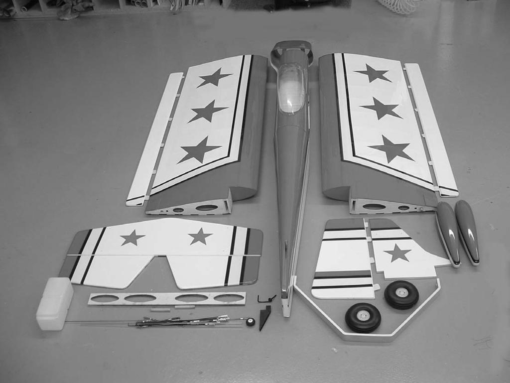
3 3


4 Wing Assembly Start with one wing panel. Locate the aileron and trial fit them on the wing. You will need to determine which aileron is the left and which is the right by trial fitting. Make sure all the hinges are aligned and the aileron is flush with the wing tip. Now locate the other aileron and wing panel and fit the aileron. When you are satisfied with the fit remove the ailerons and lay them behind the wing in the correct position. The pin style hinges work best if installed in both wing and aileron at the same time. Apply a drop of oil in the hinge.use 30 minute epoxy to glue them in. A syringe works great, if you don t have one use a 1/8 dowel or piece of 3/32 wire to get the epoxy into the holes. With glue in the holes, push the hinges in wing up to the pin. Apply glue in the holes on the aileron and slide aileron into place. Work the aileron up and down several times and the pin hinges will rotate into position. Make sure you have a tight fit between the wing trailing edge and aileron leading edge. Set aside to dry and install the other aileron. Assembly Instructions from the holes in the front of the wing. Insert the dowel in the hole and through the hole in the dihedral brace. Now slide the other wing panel on the dihedral braces and insert dowel in hole. Locate the dihedral brace. Trial fit the brace into the slot with the holes aligned with the holes in the wing. Locate the two 3/8 x 1-3/8 dowels and make a mark 1/2 in from one end. Using an exacto knife, remove the covering Both dowels should go completely through the dihedral brace and leave 1/2 exposed. 4


5 When satisfied with fit and alignment, take the wings apart. Mix 3 ozs. of 30 minute epoxy and apply a liberal amount to the root of both wings, both sides and the edges of the dihedral brace, and into the slots of both wings. Use a scrape piece of wood to work the epoxy down into the slots in the wings. Slide the dihedral brace into place and apply epoxy in the holes for the 3/8 dowels and install dowel. Slide the other wing in place and install dowel. Use masking tape to hold the wing together till the epoxy cures. Check the trailing edge of the wing and use a pin to make sure it stays in perfect alignment. Lay the wing down on a flat surface till the epoxy cures, don t stand it on one tip. This will cause the epoxy to run to one end. Use a yard stick to measure from the rear corner of the stab to the front edge of the turtle deck. Move stab until this measurement is the same on both sides. Sight the stab, fin, wing alignment from the rear of the plane. The alignment can be changed slightly by pushing up or down on the stab tip. This is all that should be needed, but if more is needed you can sand the stab saddle till the alignment is perfect. Tail Assembly With the wing mounted on the fuselage, slide the stab into the slot in rear of fuselage. Slide the fin into place in the slot on the top of fuselage. Do the same with the fin. When happy with the alignment, use a marking pen and mark a line on the stab, top and bottom and on both sides of the fuselage. Do the same to both sides of the fin. 5


6 Using 30 minute epoxy, glue the stab and fin in place using the marks made earlier to align. Use masking tape to hold in place if necessary. Check alignment and allow epoxy to cure. Trial fit the elevators and rudder in place. Glue the hinges in using the same method as you did on the ailerons. The photos show CA hinges which were used on the prototype but the kit is supplied with pin type hinges. Remove stab and fin from fuselage and using a razor blade, remove the covering between the lines you just marked. Cut about 1/8 inside your mark so bare wood will not be exposed when glued in place. Cut carefully and cut only the covering, don t cut the balsa underneath as this would weaken the stab and fin. remove covering Locate the hole for control horn in the bottom of the rudder. remove covering 6
.")


7 Flying Wires Assembly The flying wires are functional on the Stinger1.2 and must not be omitted. Locate the 12 flying wire brackets and bend a 45 degree angle on the end even with the notch. ( hardware may vary from what is shown in the pictures). Attach the brackets to the stab and fin with six 2mm x 20mm screws and nuts. Locate the pre-drilled holes in the stab and fin by measuring down approximately 2-7/8 from the top of the fin and approximately 1/2 in from the leading edge and trailing edge. Press down the covering and with a pin you should be able to locate the hole. Remove the covering using a knife. On the stab measure in approximately 4-1/2 from the tip and approximately 1/2 in from the leading and trailing edge. Attach brackets to both top and bottom of stab, and both sides of fin. Locate the eight 2-mm rods, 2mm clevises, nylon swing in keepers, and clevis retainer silicone tubing. Screw the clevis approximately half way on the threads of the rod and attach to the bracket on the fin.. Insert the 90 degree bend into the bracket and attach the swing in keeper. brackets Install the other 3 wires on top in the same manner. Be careful not to put pressure on any of the surfaces, after all the wires are installed we will adjust the tension. 7


8 Landing gear Install the bottom flying wire bracket to the bottom of the fuselage with two 2mm screws. The landing gear holes are predrilled approximately 6 behind the front of the fuselage. Press down the covering to find the holes and remove the covering with a knife. Place the gear over the holes with the rake in the gear going to the rear. Secure in place with the two 4mm x 20mm bolts into the pre-installed blind nuts. Use lock-tite on the bolts to make sure they don t vibrate loose. Install the bottom flying wires in the brackets using the nylon swing in keepers. When all wires are installed adjust each one so there is no play in the rod. Don t over tighten the clevis so as not to twist or bend the stab and fin. 8


9 Install the axles in the pre-drilled holes in the landing gear using the aircraft locknuts. Be careful and don t over torque the bolts or they will break easily. Install one of the 3/16 wheel collars on the axel approximately 3/16 in from the landing gear. This will space the wheel in the middle of the wheel pant. Adjust later if necessary. Assemble the tail wheel bracket by sliding the tail wheel wire through the plastic bracket and secure on top with the special collar. Thread the tiller rod through the top portion and secure with set screw. Screw the nylon control horns on each end of the tiller rod. The wheel pant has a 1/2 hole in one side that will fit over the inside nut on the wheel pant. Slide the wheel pant and wheel on at the same time and install the outside 3/16 wheel collar. You should file a flat spot on the axel where the set screw for the wheel collar fits. Screw the wheel pant to the axel using the 3mmx20 screw into the blind nut on the inside of the wheel pant. Be sure and use thread lock compound on the screw. Bolt the tail wheel bracket in place using the three 2mm screws. Install the tiller bracket on the rudder using two 2mm screws. Connect the springs between the tiller arm on the rudder and the one on the tail wheel arm. Install the wheel using the 3mm wheel collar. Tail Wheel Bracket 9


10 Canopy Assembly Instructions Mark around block on both sides and remover the covering on the wing under the marks. Epoxy the blocks in place. Bolt the wing in place on the fuselage using the 4mm bolts and flat washers, the blind nuts are already installed. Fit the wing cover in place with the dowel in the hole in the F2 bulkhead. Use a pencil and make a mark on the wing approximately 2-1/2 in front of the leading edge at the edge of the wing cover. Make a mark on the wing at the center of the block. Reinstall the wing cover and measure up 1/2 from the surface of the wing on the wing cover at the mark you made. Drill a 9/64 hole through the wing cover and into the block. Repeat for the other side. Remove the wing cover and enlarge the hole in the block to accept the 4mm blind nut (7/32 ). Seat the blind nut by installing the screw in the block without the wing cover in place and screwing the bolt into the blind nut pulling it into the wood. Very carefully glue the blind nut in place on the back side making sure not to get glue into the threads. Remove the bolts and reinstall the wing cover with the bolts in place. Remove the wing cover and measure over from the line you drew 3/16. This should be at the outside edge of the wing bolt reinforcement plate at the trailing edge of the wing. Take the two 3/8 x 1-3/8 x 7/8 wooden blocks and place on this line at the front of the wing bolt reinforcement plate. 10


11 Draw a center line on the firewall from top to bottom. Draw a line across the firewall through the center of the hole, this is the trust line. You can mount your engine centered on these marks. Depending on the engine you use, you may want to use 2 degrees right thrust. This will offset the engine 3/16 to the left side of the firewall. The length of the cowl from the firewall to the nose ring is 6-1/2. This can be adjusted about 1/4 either way but your engine should be spaced to fit at this length. Trim the clear canopy to the scribe line and trial fit.this should be done with the wing bolted in place and the wing cover bolted in place. If you are using a pilot or cockpit detail, now is the time to install it. When satisfied with the fit, glue in place with a bead of Zap Formula 560 canopy glue. This glue is white going on but will dry clear. Put about a 1/4 wide bead around the base on the inside and hold in place with masking tape until dry. Depending on heat and humidity it make a couple of days to get completely clear, but will be dry enough to use in about 8 hours. Any smudges can be cleaned with water while the glue is still wet. Engine Mounting Offset for right thrust Bolt the engine in place using bolts with aircraft lock nuts on the back side (not included in kit). It is a good idea to go over the glue joints between the fuse and firewall on the inside with epoxy to make sure the joint is glued securely. Thrust line 11


12 Cowl Mounting Assembly Instructions cowl mount blocks drill and pin 4 spots Locate the two shaped cowl mount blocks and locate them on the top of the fuselage flush with the front of the firewall.. Mark around them and remover the covering. Epoxy in place Drill four 3/32 holes and pin to firewall using round toothpicks and epoxy. Drill one hole in the center of the cowl making sure it goes into the firewall. Make the necessary cutouts in the cowl to fit over the engine you have installed. Slide the cowl in place so it overlaps the fuselage at least 3/8 top and bottom. Install the spinner back plate on your engine and leave 1/8 gap between the cowl and back plate. Tape the cowl in place and drill a 1/16 pilot hole through the cowl into the mounting blocks on each side at the top. Drill two screw holes on each side of the cowl at the bottom again making sure they go into the firewall and not just the fuselage side. Secure the cowl in place using the 3mm screws. 12


13 Radio Installation Install the aileron servos in the wing using the hardware that comes with the radio. The servo should be turned so the arm is position toward the rear of the wing and on the outboard side of the servo. Use the factory installed nylon fishing line to pull the aileron lead to the hole in the center of the wing. You will have to use a y- connector to tie the two servos together and a 12 extention to reach the center of the wing Assembly Instructions With the servo centered, adjust the linkage till the aileron is centered. Tighten the 4-40 jam nuts on each end and install the clevis keeper on each clevis. Don t forget to install the servo arm retaining screw. Put a drop of thread lock on both jam nuts. Align the control horn with the servo arm and screw in place using the #2x3/4 screws. The screws go into a plate on the top side of the aileron. The connection holes in the control horn for the pushrod should be aligned over the hinge line. Locate the 4-40 x 4 pushrods and install a 4-40 nut on each end. Screw a 4-40 clevis on each end and connect one end to aileron horn and the other to the servo arm. Install the elevator servos in the tail. You will need a 24 extension for each servo. Install the control horns using the #2 x3/4 screws into the plate on top for the elevators. Align the holes for the pushrod over the hinge line and mount as close to the inboard edge of the elevator as possible. Locate the two 7-1/2 long 4-40 pushrods, clevises, jam nuts and silicone keepers. Install a clevis on each end of the pushrod and connect the servo to the elevator control horn. 13


14 With the servos centered, adjust the linkage so the elevators are centered. Tighten the jam nuts and apply a drop of lock tite to each. Install the silicone clevis keeper and the servo arm screw. Install the rudder servo in the fuselage in the rail provided. Center the servo in the fuselage. Locate the four cable fittings and four swages. Thread the cable through the swage, throught the fitting and back through the swage. Pull the swage to about 1/8 from the fitting and crimp. Cut the cable into two equal lengths and install a fitting on the other cable. Put a jam nut and clevis on each fitting. Attach the clevis to the rudder horn on each side and feed the cable through the slots on the side of the fuselage. You will need to remove the covering over the pre-cut slots in the fuselage sides. Install a long control arm on the rudder servo. Screw a jam nut and clevis on the two remaining control cable fittings. Attach the clevises to the control arm on the servo. With the servo centered and the rudder centered, thread the control cable through the swage, through the fitting and back through the swage. Do both sides before crimping and pull tight and make sure servo and rudder are centered. Crimp the swage and cut the cable just behind the crimp. Install the rudder control horn in the hole provided in the bottom of the rudder. The horn is a 3 long 6-32 bolt with nuts and washers on each side. Use locktite on the nuts. Install the nylon fittings on each end. 14


15 Throttle Servo mount Locate the throttle servos mount and glue the 3/8 square spruce block and the 1/8 ply angles in place. Mount the servos to the plate using the hardware supplied with the radio. The servo mount can be glued to the side of the fuselage just in front of the F2 bulkhead (the one with the wing dowel holes). There will be room for the fuel tank below it and the ignition system can sit on top of the tank. Install the E-Z connector (supplied) to your servo arm. Take the 2-56x12 push rod and install the 2-56 jam nut and the clevis. Drill a hole in the firewall to line up with the throttle arm on your engine. Install the pushrod with the clevis on the engine and the other end in the E-Z connector. This set up shows a Fox 2.4, if you are using a different engine you will have to adjust accordingly. 15


.")
16 On our Fox 2.4 installation a hole was cut in the firewall to allow the ignition wire to pass through. The module sits on top of the fuel tank and a switch is installed in the fuselage in the nose section. A hole is drilled at the top of the firewall to allow the ignition pickup wire to pass through and the fuel line holes are drilled just above the carb. Assemble the fuel tank so the klunk is about 1/4 off the bottom of the tank and free to flop about. If you are using glow fuel you must use silicone tubing and if you are using gasoline you must use tygon or neoprene tubing. The tank supplied has a gas stopper and neoprene tubing. If you use glow you must replace these. Install the tank in the nose section and drill the appropriate holes. The radio receiver and switch can be mounted in the rear section of the compartment under the wing (there is lots of room). Depending on the engine used, the battery (or batteries if ignition is used) can be mounted where needed for balance. With the Fox 2.4, both batteries were mounted as far to the rear as possible. 16
17 The Stinger 120 has a wide CG range and can be very docile at the forward setting, 4-1/2 inches. For expercienced pilots it can be moved back past our rearward recommendation by an iinch or more for unlimited aerobatics. Control Throws Low Rate Elevator 1 up and down Aileron 3/4 up and down Rudder 1-1/2 each way High Rate Elevator All you can get Aileron All you can get Rudder All you can get Center of Gravity 4-1/2 to 5 behind leading edge 17
18 Parts List Airframe components 1. Fuselage 1 2. Wings 2 3. Aileron 2 4. Stab 1 5. Fin 1 6. Rudder 1 7. Elevators 2 8. Wing cover 1 9. Clear Canopy Landing gear Wheel pants Cowl 1 Wing Hardware 1.Dihedral brace 2. 3/8 x 1-3/8 dowels 2 3. Control horns 4 4. Control horn plates 4 5. Control horn screws 8 #2x3/ clevises nuts 8 8. clevis keepers x4-3/4 pushrod 4 10.Wing bolts 2 6mm x40mm Flying wire hardware rods clevises 8 3. Clevis retainers 8 4. Nylon swing in keepers 8 5. Aluminum bracket 1 6. Flying wire brackets #2 x3/4 socket head screws 6 8. #2 nuts 6 9. sheet metal screws tail wheel and flying wire bracket 2 Elevator, Rudder Hardware 1. Control horns 2 2. Control horn plates 2 3. Control horn screws (Elevator)#2x3/ x 7-1/2 control rods (Elevator 2) x 3 threaded rod 1 rudder horn nuts 2 7. nylon pushrod ends nuts (elevator pushrods) clevises (elevator) 4 10 Clevis keepers 4 rudder 4 elevator braided cable cable swages 4 Landing Gear Hardware 1. Main gear bolts 1/4 x3/ /2 wheels /16 x 2 axles with nuts /16 wheel collars mm bolts for wheel pants 2 8. Tail wheel assembly 1 9. Spring for tail wheel /8 wheel collar /4 tail wheel 1 18
19 Canopy Mounting Hardware 1. Phillips head metric screws 3mm x 20mm 2 2. Flat washers 2 Fuel tank 16 oz. Decal Sheet 1 Instruction Booklet 1 Assembly Instructions Adhesives 1. Thin CA (cyanoacrylate) glue 2. Medium CA. Glue 3. CA remover/debonder 4. 5-Minute Zap Z-Epoxy Minute Zap Z-Epoxy 6. Zap Z-42 Threadlock 7. Zap Canopy glue. Throttle Hardware 1. E-Z connector pushrod clevis nut 1 5. Lite-ply servo mount /8 sq. x 3/4 spruce blocks 2 Tool need to complete the Stinger. 1. Drill and assorted bits 2. Hobby Knife with #11 blade 3. Masking Tape 4. T-pins or straight pins 5. Felt tipped pen/pencil 6. Rubbing alcohol 7. Paper towels 8. Phillips screwdriver 9. Allen wrenches 10. Metric tap 6mm. 11. Pliers (needle nose) 12. Mixing sticks yard stick or tape measure 14. Scissors 15. Moto tool with sanding drum. Equipment Required 1. Four channel radio or better 2. Servos- 70in.oz. or better mah battery pack or larger 4. Y-connectors extensions (Aileron) extensions (Elevators) 2 If you have a programmable radio that will allow you to mix two channels to control the two elevator servos you will not need a servo reverser. If not you will need 1 servo reverser, and one more Y- Connector. 7. Heavy duty control arms to fit your servos. 8. Switch harness (your radio) 9. Motor (gas or glow) If gas, battery pack, and switch for ignition. 10. Prop and 3-1/2 Spinner for your motor. 11. Fuel line (for gas or glow) 12. Pilot figure (optional) 19
Assembly Instructions STINGER
 STINGER 120 ARF Important Information: Please inspect the plane before beginning to assemble to make sure you are happy with it. After assembly has begun you cannot return the kit. If you find a problem
30% Edge 540T Almost Ready to Fly
 Lanier R/C 30% Edge 540T Almost Ready to Fly WARNING! THIS IS NOT A TOY! THIS IS NOT A BEGINNERS AIRPLANE This R/C kit and the model you will build from it is not a toy! It is capable of serious bodily
Combat plane for Open B Lanier R/C Inc. P.O. Box 458 Oakwood, GA Phone Fax copyright 2003 Lanier R/C
 Combat plane for Open B Lanier R/C Inc. P.O. Box 458 Oakwood, GA. 30566 Phone 770 532 6401 Fax 770 532 2163 copyright 2003 Lanier R/C Important information: Please inspect the plane before beginning to
Hot Stik ARF WARNING. Copyright 2005 Carl Goldberg Products LTD CARL GOLDBERG PRODUCTS, LTD.
 Hot Stik ARF INSTRUCTIONS WARNING A radio-controlled model is not a toy and is not intended for persons under 16 years old. Keep this kit out of the reach of younger children, as it contains parts that
67 Edge 540 ARF WARNING
 67 Edge 540 ARF INSTRUCTIONS WARNING A radio-controlled model is not a toy and is not intended for persons under 16 years old. Keep this kit out of the reach of younger children, as it contains parts that
FUSELAGE CONSTRUCTION
 FUSELAGE CONSTRUCTION Note: prior to building and gluing on the work surface use protective covering on your building surface. (wax paper or clear wrap) Fit the laser cut Fuselage Front and Fuselage Rear
Corvus Racer CC
 Corvus Racer 540 35CC Item No:L-G035008 Specifications Wing Span Length Wing Area Flying Weight Glow Gasoline Electric Radio mm mm 1200sq in (77.4sqdm) 9.9-12lbs(4.5-5.5kg) 91-1.20(2C) 1.10-1.40(4C) 20-40cc
77 Edge 540 ARF WARNING
 77 Edge 540 ARF INSTRUCTIONS WARNING A radio-controlled model is not a toy and is not intended for persons under 16 years old. Keep this kit out of the reach of younger children, as it contains parts that
LANDING GEAR. 1. Fit landing gear into slots on bottom of fuselage.
 LANDING GEAR 1. Fit landing gear into slots on bottom of fuselage. 4. Use channel-lock pliers to press blind nuts into position (note: drilled hole should be slightly smaller than shaft of blind nut for
RYAN STA SAFETY PRECAUTIONS. "Sport Scale E-Power ARF" For Intermediate and Advanced Fliers. This radio control model is not a toy!
 RYAN STA "Sport Scale E-Power ARF" For Intermediate and Advanced Fliers. SAFETY PRECAUTIONS This radio control model is not a toy! First-time builders should seek advice from people with model building
Edge 540 V3 35CC. Scheme A. Item No:L G Specifications. Flying Weight
 Edge 540 V3 35CC Item No:L G035016 Specifications Wing Span Length Wing Area Flying Weight Glow Gasoline Electric Radio Description 76 (1930mm) 74 (1879mm) 1200sq in(77.4sqdm) 9.9 12lbs(4.5 5.5kg) 91 1.20(2C)
EXTRA 330SC 60CC. Item No:H G Specifications cc gas DA50,DA60, DLE55, DLE60(twin), 3W55. Description
, 3W55. Description") EXTRA 330SC 60CC Item No:H G060011 Specifications Wing Span Length Wing Area Flying Weight Gasoline Radio Description Carbon Fibre : 92" (2347mm) 84 1/2 " (2060mm) 1526.8 sq in(98.5sq dm) 16 17lbs(7300
EXTRA 330SC 60CC Item No:H G060011 Specifications Wing Span Length Wing Area Flying Weight Gasoline Radio Description Carbon Fibre : 92" (2347mm) 84 1/2 " (2060mm) 1526.8 sq in(98.5sq dm) 16 17lbs(7300
MXS R 30CC. Item No:L G Specifications. 67 1/2"(1720mm) (2C) (4C) 26 35cc gas DLE 30/35RA MLD35 JC30Evo.
 (2C) (4C) 26 35cc gas DLE 30/35RA MLD35 JC30Evo.") MXS R 30CC Item No:L G030008 Specifications Wing Span Length Wing Area Flying Weight Glow Gasoline Electric Radio Description Covering Material Carbon Fibre : 75"(1915mm) 67 1/2"(1720mm) 1023sq in(66sq
MXS R 30CC Item No:L G030008 Specifications Wing Span Length Wing Area Flying Weight Glow Gasoline Electric Radio Description Covering Material Carbon Fibre : 75"(1915mm) 67 1/2"(1720mm) 1023sq in(66sq
105" TIGER MOTH ARF INSTRUCTION MANUAL VERSION 1.0
 105" TIGER MOTH ARF INSTRUCTION MANUAL VERSION 1.0 Step 1. Installation of the aileron servos 1) Mount aileron servo to servo mounting blocks with servo s screws. Install servo mounting plate with screws.
MECOA EZ-4061 Trainer
 MECOA EZ-4061 Trainer EZ-4061 is a newly designed, Almost Ready to Fly kit. It is an extremely easy to control trainer with strong construction and excellent aerodynamic performance. This is a great choice
LANIER Dominator INSTRUCTIONS
 ADDITIONAL EQUIPMENT NEEDED TO COMPLETE YOUR DOMINATOR 500 General 3.2 to 4.2 Size two stroke R/C engine, muffler, and engine mount Gas or glow fuel line Minimum of 4 channel radio set required (4-5) 70
Building Instructions P-51 BF109
 Building Instructions P-51 BF109 Sport model for.015 engines. Legal for SSC Warbird Lanier R/C Inc. P. O. Box 458 Oakwood, Ga. 30566 Copyright 2004 Lanier R/C Inc. Important information: Please inspect
CARL GOLDBERG PRODUCTS, LTD.
 Pitts Monster Aerobatic flying just doesn't get any better than this Pitts ARF. The classic lines of a biplane coupled with the radial cowl, add excitement to the maneuvers you love, knife edge, split
Corvus Racer Colour schemes. AeroPlus RC Copyright 2013 All Rights Reserved
 Corvus Racer 540 59 Item No:A E050003 Specifications WING SPAN: 59"(1500mm) LENGTH: 54.1"(1374mm) WING AREA: 654sq.in.(42.2sq.dm.) FLYING WEIGHT: 4.6 5.3lbs(2000 2300g) Electric:Brushless outrunner 8Oz.
Extra 330LT CC. 2 Colour schemes H-G120001A ORACOVER FERRARI RED # ORACOVER WITH # ORACOVER BLACK # ORACOVER SILVER #
 Extra 330LT 85-125CC Item No:A-G120001 Specs: WING SPAN: LENGTH: WING AREA: FLYING WEIGHT: ENGINE: RADIO: Description Covering Material Carbon Fibre: 111 (2833mm) 100" (2530mm) 2139sq in (138sq dm) 25.3-28lbs
TIGER SHARK-40 ARF ASSEMBLY MANUAL
 TIGER SHARK-40 ARF ASSEMBLY MANUAL Kangke Industrial USA, Inc. 65 East Jefryn Blvd. Deer Park NY 11729 http://www.kangkeusa.com E-mail: info@kangkeusa.com Tel: 1-877-203-2377 Fax: 1-631-274-3296 Congratulations!
94 Yak 54 ARF WARNING
 94 Yak 54 ARF WARNING A radio-controlled model is not a toy and is not intended for persons under 16 years old. Keep this kit out of the reach of younger children, as it contains parts that could be dangerous.
87 Extra 330 ARF WARNING
 87 Extra 330 ARF WARNING A radio-controlled model is not a toy and is not intended for persons under 16 years old. Keep this kit out of the reach of younger children, as it contains parts that could be
Assembly Manual / Airframe 65 Vyper SAFETY in Assembly SAFETY in Flying
 1 Assembly Manual / Airframe 65 Vyper Thank you for purchasing this 3DHobbyShop ARF RC aircraft. If you have any issues, questions, concerns or problems during assembly, please contact our tech department
Instruction Manual. Specification:
 Instruction Manual H I G Specification: Wingspan: 133 cm (52.3 inches) Length : 104 cm (40.9 inches) Weight : 1830gr Engine : 25-32 two stroke Radio : 4 channel - 4 servo H W I N G KIT CONTENTS: We have
Instruction Manual book
 Instruction Manual book ITEM CODE BH53. SPECIFICATION Wingspan : 1,250mm 49.21 in. Length : 930mm 36.61in. Weight : 1.1kg 2.42 Lbs. Parts listing required (not included). Battery: 3 CELLS-LI-POLY-11.1V-2,500
Citabria Pro. Aerobatic Parkflyer. by Joel Dirnberger
 Citabria Pro Aerobatic Parkflyer by Joel Dirnberger Revision C: December 21, 2004 Citabria Pro Building Instructions Length: Wingspan: Wing Area: Flying Weight: Wing Loading: Functions: Specifications:
INSTRUCTION MANUAL BOOK.
 INSTRUCTION MANUAL BOOK. SPECIFICATION Wingspan : 164 cm 64.57in. Length : 135 cm 53.15 in. Weight : 3.3kg 7.26 lbs. Servo : 7 servos. Radio : 4 channels. Engine : 61 cu.in-2 stroke. 91 cu.in-4 stroke.
LANIER - Double Trouble - INSTRUCTIONS. Tail 1 T1 ¼ Balsa 1 T2 ¼ Balsa 2 T3 ¼ Balsa 1 T4 ¼ Balsa 1 T5 ¼ Balsa 1 T6 ¼ Balsa 2 J1 ¼ Balsa 2 J2 Lite ply
 Tail 1 T1 ¼ Balsa 1 T2 ¼ Balsa 2 T3 ¼ Balsa 1 T4 ¼ Balsa 1 T5 ¼ Balsa 1 T6 ¼ Balsa 2 J1 ¼ Balsa 2 J2 Lite ply Other Parts 2 Aluminum Gear 1 3/32 Music wire tail skid 2 Elevator and J-plane joiner wire
Hand-made Almost Ready to Fly R/C Model Aircraft ASSEMBLY MANUAL
 Hand-made Almost Ready to Fly R/C Model Aircraft ASSEMBLY MANUAL Specifications Wingspan -----------------------.148 cm--------------- 58.3 in. Wing area ----------------------- 3474sq. cm ---- 538.4sq
Instruction Manual. Item No: AL001
 Instruction Manual Item No: AL001 Specifications: Wingspan: 2037mm (80.2 in) Length: 1677mm (66 in) Wing Area: 65.5dm2 (1015.3 sq in) Flying Weight: 7.6kg (16.7 lbs) Engine(not incl.): 45-50cc Gas Radio(not
F3A -70E ASSEMBLY MANUAL
 F3A -70E ASSEMBLY MANUAL The new F3A-70E, was designed in an extremely lightweight structure, the all wood airframe, and the new revolutionary Lift Generator on landing gear give the F3A-70E an impressive
TWEETY 25 INSTRUCTION MANUAL. Almost Ready to Fly Nitro/Electric Aerobat FEATURES SPECIFICATIONS
 TWEETY 25 Almost Ready to Fly Nitro/Electric Aerobat INSTRUCTION MANUAL SPECIFICATIONS FEATURES WINGSPAN: 45.7 (1160mm) LENGTH: 38.6 (980mm) WING AREA: 370 sq in(24 sq dm) FLYING WEIGHT: Approx. 3.3 lbs
E-AERO EPP PITTS KIT From BP HOBBIES. Parts Included in kit
 E-AERO EPP PITTS KIT From BP HOBBIES Parts Included in kit Thank you for purchasing the BP Hobbies/E-aero EPP Pitts. Please take the time to read through the instruction manual before beginning the build.
Thunder Tiger Ace Hobby Page 1 6/8/10
 TOC 35% Katana Assembly Manual Thunder Tiger Ace Hobby Page 1 6/8/10 Table of contents Thunder Tiger Contact Information Page 3 Introduction.Page 4 Kit Contents.Page 5 Items Needed to Complete...Page 6
WE GET PEOPLE FLYING AT-6
 TM WE GET PEOPLE FLYING AT-6 Texan.60 ARF ASSEMBLY MANUAL Specifications Wingspan:... 67.5 in (1714mm) Length:... 48 in (1219mm) Wing Area:... 706 sq in (45.54 sq dm) Weight:... 7 8.5 lb (3.17 3.85 kg)
LANIER - Ultimate Pitts - INSTRUCTIONS. Additional Parts Required. (12) 4-40 blind nuts (Dubro #606)
 4-40 blind nuts (Dubro #606)") Additional Parts Required (4) or more channel radio with 7-8 servos..91-2.2 two stroke or 1.20-1.84 four stroke engine Appropriate Master Airscrew prop and Hayes mount for your engine. 3 Tru-Turn spinner
Additional Parts Required (4) or more channel radio with 7-8 servos..91-2.2 two stroke or 1.20-1.84 four stroke engine Appropriate Master Airscrew prop and Hayes mount for your engine. 3 Tru-Turn spinner
High performance 90mm fiberglass jet
 High performance 90mm fiberglass jet Assembly manual For intermediate and advanced fliers only! Specs Wingspan: 1255mm Fuselage length: 1250mm Flying weight: 2600-3000g Wing area: 22.6 dm² Wing loading:
LANIER - Giles % - INSTRUCTIONS
 Additional Parts Required (4) or more channel radio with 4 servos..25 -.36 two stroke or.40 -.52 four stroke engine Appropriate Master Airscrew prop and Hayes mount for your engine. 2-1/2 Tru-Turn spinner
SebArt professional line
 SebArt professional line Wind S 110 ARF ASSEMBLY MANUAL The new Wind S 110 ARF was designed by Italy aerobatic pilot, Sebastiano Silvestri. This professional ARTF kit is the result of Sebastiano s 20 years
WE GET PEOPLE FLYING INSTRUCTION MANUAL
 TM WE GET PEOPLE FLYING INSTRUCTION MANUAL 90% prebuilt Giant scale legal Precovered with genuine UltraCote Featuring one-of-a-kind scale trim scheme Prefinished fiberglass cowl Gas or glow option Specifications
Aviator Trainer40 ARF Instruction Manual Specifications
 Aviator Trainer40 ARF Instruction Manual Specifications Wingspan: 65.0 in (1650 mm) Length: 53.1 in (1350 mm) Wing Area: 729sq in (47.0 sq dm) Flying Weight: 5.3 lbs (2400g) Dear Customer, Congratulations
C-180 Builder s Manual
 C-180 Builder s Manual. May 20, 2002 Last revised July 11, 2002 Copyright! 2002 Douglas Binder, Mountain Models www.mountainmodels.com sales@mountainmodels.com (719) 630-3186 1 Required Equipment! Xacto
CARL GOLDBERG PRODUCTS, LTD.
 Eagle 400 WARNING A radio-controlled model is not a toy and is not intended for persons under 16 years old. Keep this kit out of the reach of younger children, as it contains parts that could be dangerous.
LANIER R/C. Stinger WARNING! THIS IS NOT A TOY! THIS IS NOT A BEGINNERS AIRPLANE LIMITED WARRANTY
 LANIER R/C Stinger WARNING! THIS IS NOT A TOY! THIS IS NOT A BEGINNERS AIRPLANE This R/C kit and the model you will build from it is not a toy! It is capable of serious bodily harm and property damage.
THE APOGEE A 100-INCH AMA DURATION SAILPLANE FROM DYNAFLITE
 THE APOGEE A 100-INCH AMA DURATION SAILPLANE FROM DYNAFLITE Apogee is the intermediate sailplane designed to be competitive in AMA duration contests. Effective spoilers, rudder and full flying stabilizer
INSTRUCTIONS FOR FINAL ASSEMBLY
 MS: 11 INSTRUCTIONS FOR FINAL ASSEMBLY Graphics and specfications may change without notice. Specifications: Wingspan -------------------------------------------- 156 cm, 61.42 in. Wing area ---------------------------------
Super Sky Surfer 2000 Assembly Instructions
 Super Sky Surfer 2000 Assembly Instructions Note: Plug and Play version of the Sky Surfer comes with fuselage pre-glued and motor/servos installed. If you wish to route antennas or wires through the tail,
CARL GOLDBERG PRODUCTS, LTD.
 Chipmunk 400 WARNING A radio-controlled model is not a toy and is not intended for persons under 16 years old. Keep this kit out of the reach of younger children, as it contains parts that could be dangerous.
MUSTANG P-51. Hand-made Almost Ready to Fly R/C Model Aircraft ASSEMBLY MANUAL
 MUSTANG P-51 Hand-made Almost Ready to Fly R/C Model Aircraft ASSEMBLY MANUAL Specifications Wingspan---------------------------------------- 60.5 in----------------------- 153.7cm. Wing area-------------------------------------
Hobby Lobby Zip Supplementary instructions Please refer to the included drawings while using these assembly instructions
 Materials needed: 15 or 30 minute epoxy Medium CA Masking tape Scotch tape Servo Tape Wax paper Tools Needed: Pencil or marker Flat building surface Hobby knife or razor blade 7/64" or 3mm drill bit 3/16"
90 WING SPAN P-51D MUSTANG (COPYRIGHT PROTECTED 2014) ALL RIGHTS RESERVED
 ALL RIGHTS RESERVED") 90 WING SPAN P-51D MUSTANG (COPYRIGHT PROTECTED 2014) ALL RIGHTS RESERVED GENERAL INSTRUCTIONS This design is basically an enlargement of the very popular fun scale Mustang 60 Size. You can build it light
90 WING SPAN P-51D MUSTANG (COPYRIGHT PROTECTED 2014) ALL RIGHTS RESERVED GENERAL INSTRUCTIONS This design is basically an enlargement of the very popular fun scale Mustang 60 Size. You can build it light
RESolution V2 Manual
 RESolution V2 Manual Note for the German Manual: Yellow Bottle thick CA Pink Bottle Med CA Blue tube 5 minute Epoxy Green tube 90 Minute Epoxy Construction of the Fuselage Step 1: Cover the plan with a
Sbach 1,2m 3D/aerobatic EPP model Building instructions
 Sbach 1,2m 3D/aerobatic EPP model Building instructions Please refer to the Diagram sheet Diagrams A, B Press 2 carbon strips (1x3x1000 mm) into the grooves in the sides of the fuselage central part (the
This pictorial document contains assembly recommendations including some fit and finish details that will be helpful when building this airplane
 This pictorial document contains assembly recommendations including some fit and finish details that will be helpful when building this airplane Problems found with this kit and a flight performance review
A S S E M B L Y M A N U A L
 A S S E M B L Y M A N U A L Kit features. Ready-made minimal assembly & finishing required. Ready-covered covering. Photo-illustrated step-by-step Assembly Manual. Specifications Wingspan --------------------------
AT channel 6 servos
 Wing Span: Wing Area: Fuselage Length: Flying weight: Power system: Radio: 60.7in/1540mm 561 sq in/36.3 sq dm 44.1in/1120mm 6.9 Ibs/ 3100g 46(2C0/71(4C) 5 channel 6 servos AT6-46 INSTALLING AILERONS Begin
PERCIVAL P-56 PROVOST
 Instruction Manual Book. PERCIVAL P-56 PROVOST OLEO STRUTS LANDING GEAR. ALL BALSA - PLY WOOD CONSTRUCTION. COVERED WITH ORACOVER Glow and EP 95% ALMOST READY TO FLY SPECIFICATION: - Wingspan: 1,644mm
(Build Instructions)
") (Build Instructions) Specifications * Wingspan: 58cm * Length: 50cm * Flying Weight: 59 grams * Channels: 3 (Rudder Elevator Throttle) * Suggested Receiver: 4Ch Micro * Motor: 8mm GearDrive * Prop: GWS
(Build Instructions) Specifications * Wingspan: 58cm * Length: 50cm * Flying Weight: 59 grams * Channels: 3 (Rudder Elevator Throttle) * Suggested Receiver: 4Ch Micro * Motor: 8mm GearDrive * Prop: GWS
43in EPP Acrocub Instruction Manual
 43in EPP Acrocub Instruction Manual Specifications Wingspan: 43.3in (1100mm) Length: 41.3in (1050mm) Flying Weight: Approx. 1.5lb (670g) Dear Customer, Congratulations on your purchase of 43in EPP Acrocub
96 WING SPAN SPITFIRE (COPYRIGHT PROTECTED 2014) ALL RIGHTS RESERVED
 ALL RIGHTS RESERVED") 96 WING SPAN SPITFIRE (COPYRIGHT PROTECTED 2014) ALL RIGHTS RESERVED GENERAL INSTRUCTIONS Should you elect to use the recommended Door Skin, which is 1/8 mahogany plywood measuring 36 x 88. Have it cut
96 WING SPAN SPITFIRE (COPYRIGHT PROTECTED 2014) ALL RIGHTS RESERVED GENERAL INSTRUCTIONS Should you elect to use the recommended Door Skin, which is 1/8 mahogany plywood measuring 36 x 88. Have it cut
TIGER MOTH 120 ASSEMBLY INSTRUCTIONS
 TIGER MOTH 120 ASSEMBLY INSTRUCTIONS SPECIFICATIONS Wing Span: Length: Radio: Flying Weight: 1920mm 1580mm 4 channel with 6 servos 4200g AILERON ASSEMBLY 1 Start by removing the servo cover from the bottom
Admas A500. Specification:
 Admas A500 Specification: Length :07 mm(8.7") Wing Span :00 mm(9.5") Wing Area :8.8 sq. dm 5.5 sq. ft Wing Loading :3 g/sq. dm 53.7 oz/sq. ft Flying Weight :8 kg(7.lbs) Radio :ch &3 servos Engine : -cycle
BOOMERANG TORUS. Aerobatic Sport Jet for 20 to 34 lbs (P80 to P160) thrust turbines.
 thrust turbines.") BOOMERANG TORUS Aerobatic Sport Jet for 20 to 3 lbs (P80 to P160) thrust turbines. Specifications: Span... 83" (2209mm.) Span with Wingtip Tanks 90" (2286mm.) Length...87" (2108mm.) Weight 29 Lbs.(13.15
BOOMERANG TORUS Aerobatic Sport Jet for 20 to 3 lbs (P80 to P160) thrust turbines. Specifications: Span... 83" (2209mm.) Span with Wingtip Tanks 90" (2286mm.) Length...87" (2108mm.) Weight 29 Lbs.(13.15
Thank you for your purchase of the Lee Ulinger, FoamtanaS, Yak-55, or Extra 330 3D Depron foam, Aerobatic airplane.
 Thank you for your purchase of the Lee Ulinger, FoamtanaS, Yak-55, or Extra 330 3D Depron foam, Aerobatic airplane. Tools you will need to build Recommended additional items: #11 hobby knife Motor: Hacker
62 AJ Acuity Assembly Instructions
 62 AJ Acuity Assembly Instructions Congratulations The all-new AJ Aircraft Acuity was designed to give you all of the precision flight abilities of expensive composite aircraft, in a more traditional balsa
84 Turbo Bushmaster. Copyright 2016 Extreme Flight
 84 Turbo Bushmaster Copyright 2016 Extreme Flight 1 Please take a few moments to read this instruction manual before beginning assembly. We have outlined a fast, clear and easy method to assemble this
HIGH-END TECHNOLOGY. Electric ducted fan Starfighter
 HIGH-END TECHNOLOGY RC Electric ducted fan Starfighter First we want to thank and congratulate you with your decision in buying one of our Kits. The Starfighter puts together very easily so there is not
FUJI FA-200 AERO SUBARU
 FUJI FA-200 AERO SUBARU SEMI SCALE SPORT MODEL AERO SUBARU Assembly and Operations Manual Please review this manual throughly Before assembling or Operating The AERO SUBARU Semi scale sport model We ve
SPUNKY ASSEMBLY MANUAL
 SPUNKY ASSEMBLY MANUAL Please read the tips section at the back of this manual regarding the use of laser cut parts. The proper removal and preparation of these parts is important. When laser cut, some
STEP 1 STEP 2 STEP 3. Page 2
 INSTRUCTION MANUAL Congratulations on your purchase of the Bullet ARTF - the first Almost Ready to Fly version of this classic lowwinger. Based on the original and timeless Bullet design, the new Ripmax
T-15 EDF INSTRUCTION MANUAL. Wingspan.31in. Weight..2.5 lb. EDF...70mm 12 Blade ToughJets, LLC Kittery, ME Page 1 of 22.
 TM T-15 EDF INSTRUCTION MANUAL Specifications Wingspan.31in Length..41.75in Wing Area 515 sq in EDF...70mm 12 Blade Weight..2.5 lb Radio...3 channel Motor...Brushless Battery 14.8v 2200mah 40c 2013 ToughJets,
Instruction Manual book
 Instruction Manual book ITEM CODE: BH50. SPECIFICATION Wingspan : 1,600 mm 62.99 in. Length : 1,230 mm 48.43 in. Weight : 2.5 kg 5.5 Lbs. Radio : 06 channels. Servo : 07 servos. Electric Motor : ( 02pcs
BUCKER BU 131 JUNGMANN ALL BALSA - PLY WOOD CONSTRUCTION. COVERED WITH ORACOVER
 Instruction Manual Book. BUCKER BU 131 JUNGMANN ALL BALSA - PLY WOOD CONSTRUCTION. COVERED WITH ORACOVER Glow and EP 95% ALMOST READY TO FLY SPECIFICATION: - Wingspan: 1,850 mm (72.83 in). Length: 1,660
NOORDUYN NORSEMAN. Instruction Manual Book 95% ALMOST READY TO FLY. Item code: BH157. SPECIFICATION
 Instruction Manual Book Item code: BH157. NOORDUYN NORSEMAN ALL BALSA - PLY WOOD CONSTRUCTION. COVERED WITH ORACOVER. 95% ALMOST READY TO FLY SPECIFICATION - Wingspan: 1840 mm (72.44 in). - Length: 1180
Assembly Manual / Airframe 70 Velox
 Assembly Manual / Airframe 70 Velox Thank you for purchasing this 3DHobbyShop ARF RC aircraft. If you have any issues, questions, concerns or problems during assembly, please contact our tech department
Specifications. Before commencing assembly, please read these instructions thoroughly.
 INSTRUCTION MANUAL Before commencing assembly, please read these instructions thoroughly. Specifications Wing Span: 8.5 in / 30 mm Wing Area: 330 sq in /.3 sq dm Flying Weight: 6 oz / 70 g Fuselage Length:
VT-ALLROUNDER V4 1500MM CORO 3/4 Channel Trainer Airplane
 Congratulations on your purchase of the VT- AllRounder 1500MM Trainer Airplane Kit.. Hope these build instructions help you complete the build. Though the build itself doesn't take much time, just be sure
FAIREY ALBACORE. Instruction Manual Book. Glow and EP. Item code: BH % ALMOST READY TO FLY SPECIFICATION:
 Instruction Manual Book. FAIREY ALBACORE ALL BALSA - PLY WOOD CONSTRUCTION. COVERED IN A HEAT-SHRINK FILM WITH PRINTED. Glow and EP 95% ALMOST READY TO FLY SPECIFICATION: - Wingspan: 1,693mm (66.65in).
MEMO. Assembly Manual. Warranty. Notice: Adult Supervision Required. No.3841
 MEMO Assembly Manual No.3841 Specifications: Fuselage Length 54.6 (1387mm) Fuselage Width 15.7 (400mm) Fuselage Height 17.8 (452mm) Full Equipped Weight 8.5lbs (3860g) Warranty This kit is guaranteed to
RADIO CONTROL MODEL / RC FLUGMODELL INSTRUCTION MANUAL
 RADIO CONTROL MODEL / RC FLUGMODELL INSTRUCTION MANUAL SPECIFITIONS Wingspan...57.5 in. / 146cm Length...50 in. / 127cm Engine...46 2T /.70 4T or Electric equivalent. Radio...4 ~ 6 channel Almost ready
LANIER R/C. Shrike WARNING! THIS IS NOT A TOY! THIS IS NOT A BEGINNERS AIRPLANE LIMITED WARRANTY
 Shrike WARNING! THIS IS NOT A TOY! THIS IS NOT A BEGINNERS AIRPLANE This R/C kit and the model you will build from it is not a toy! It is capable of serious bodily harm and property damage. It is your
Aichi D3A1 INSTRUCTION MANUAL SAFETY PRECAUTIONS. Specification:
 Aichi D3A Specification: Length: 50mm(0. ) Wing span: 057mm( ) Wing area: 7.sq.dm(.sq.ft) Wing loading: 99.9g/sq.dm(3.oz/sq.ft) Flying weight: 7.kg(.7lbs) Radio: ch & 7servos Engine: 0 -cycle C.G: 35mm
HAWKER HURRICANE. Instruction Manual Book 95% ALMOST READY TO FLY. Item code: BH147. SPECIFICATION
 Instruction Manual Book Item code: BH147. HAWKER HURRICANE ALL BALSA - PLY WOOD CONSTRUCTION. COVERED IN A HEAT-SHRINK FILM WITH PRINTED. 95% ALMOST READY TO FLY SPECIFICATION Wingspan: 1,520 mm (59.84
PITTS S2S CONSTRUCTION
 PITTS S2S CONSTRUCTION FUSELAGE CONSTRUCTION 1) Place the right fuselage side over the plan and mark the former positions. Place the left side over the right side and mark the former positions. Glue F1
25mm EPP SU31. Instruction Manual. Specifications
 25mm EPP SU31 Instruction Manual Specifications Wingspan: 39.4in (1000mm) Length: 42in (1070mm) Wing Area: 448sq in (28.9sq dm) Flying Weight: Approx. 1.5lb (650-710g) Dear Customer, www.valuehobby.com/su31-epp.html
EPP Rebel Z 35. White Red w/ Blue Orange w/ Blue Orange w/burgundy Other. Specs. Color - Bottom White Black Checkers Silver Checkers Other Checkers
 EPP Rebel Z 35 Specs AUW ~10.0oz Width 35.28 Length 34.67 Wing Area 1.44 sqft Horz Area 2.35 sqft Vert Area.91 sqft
FOKKER D-VII INSTRUCTION MANUAL SAFETY PRECAUTIONS. Specification:
 FOKKER D-VII Specification: Length Wing Span Wing Area :97 mm(55") :77 mm(70") :9sq.dm 9.sq.ft Wing Loading :59.g/sq.dm.9oz/sq.ft Flying Weight :.5kg(lbs) Radio Engine: :ch & 5servos :cc-cc INSTRUCTION
Assembly Instructions
 Congratulations AJ Aircra thanks you for the purchase of this airplane. Top grade materials and precision assembly has gone into this to make this a top quality aircra. Following the direcons closely,
ULS Cherokee. Ultra Low Speed aircraft for indoor RC flying. Zippkits. Specifications: Required to complete:
 Zippkits ULS Cherokee Ultra Low Speed aircraft for indoor RC flying. Specifications: Span- 28 inches Wing Area- 151 Sq/In Wing Loading- 3.0 ounces/ft Weight- 3.5 ounces RTF Build time- 1-2 Hours Radio-
SGTalon s Enterprise-A Foamie Build Guide. SGTalon s. Enterprise. Enterprise--A. Assembly Instructions
 SGTalon s Enterprise SGTalon s Enterprise--A Enterprise Assembly Instructions Page 1 4-13-2013 SGTalon s Enterprise *******Recommended Hardware******** 2.6oz 250w Motor and Speed Control with 8x6 prop
Millennium RC presents The New and Improved (now even easier to build and cover!) SSX X-Trainer Build Kit
 SSX X-Trainer Build Kit") Millennium RC presents The New and Improved (now even easier to build and cover!) SSX X-Trainer Build Kit Wing span: Approx. 42 Wing Area: 504 sq. in. Wing Loading: 6.71 oz/ sq. ft. Introduction: The Slow
Millennium RC presents The New and Improved (now even easier to build and cover!) SSX X-Trainer Build Kit Wing span: Approx. 42 Wing Area: 504 sq. in. Wing Loading: 6.71 oz/ sq. ft. Introduction: The Slow
SwitchBack Senior. SwitchBack Senior Specifications
 SwitchBack Senior SwitchBack Senior Specifications Wingspan: 55.4 in. Length: 41 in. Wing Area: 597 sq. in. Weight (Ready to Fly): 34 to 37 oz. Wing Loading: 8.2 to 8.9 oz. / sq. ft. Version 1.05, March
INSTRUCTION MANUAL. Suitable for Electric or I.C. Engine Power
 INSTRUCTION MANUAL Suitable for Electric or I.C. Engine Power Congratulations on the purchase of your Irvine Tutor 40 II Radio Control Model Aircraft. Please take some time to carefully read these instructions
LTR-14 TURNER SPECIAL
 LTR- TURNER SPECIAL Specification: Length Wing Span Wing Area :05 mm(8") : mm(95") :sq.dm sq.ft Wing Loading :0g/sq.dm 5.oz/sq.ft Flying Weight :kg(.lbs) Radio Engine: :ch & 8servos :80cc-00cc INSTRUCTION
JAMISON SPECIAL. Building Guide
 JAMISON SPECIAL Building Guide WING Mark then drill holes for wing jig rods. Slide Ribs onto jig rods Mark the rib positions on 1/16 x 1 trailing edge, 1/4 x 1/4 leading edge & 1/4 x 1/4 spars Pin ribs
P-47D Thunderbolt. Two wheel retract system Make sure to assemble retracts as instructed below. 3-way pressure inlet INSTRUCTION MANUAL
 70 Adjustment. 7 The centre of the Gravity. Side View AILERON FLAP 0mm 0mm P-7D Thunderbolt AILERON FLAP 0mm 3mm Two wheel retract system Make sure to assemble retracts as instructed below. 3-way pressure
Ryan STA Sport Scale Model Aircraft Assembly and Instruction Manual
 Ryan STA Sport Scale Model Aircraft Assembly and Instruction Manual Warning: This radio controlled model is not a toy. It requires skill to fly and is not recommended for the novice pilot. It should not
INSTRUCTION MANUAL. Specifications. Wing Area Flying Weight Fuselage Length. 28 oz / 800 g 30.0 in / 760 mm
 ALMOST-READY-TO-FLY INSTRUCTION MANUAL Requires : -channel radio w/ micro servos, Outrunner Motor w/ Propeller Adaptor 0A Brushless ESC, 3 cells 11.1V 100 mah Li - Po battery & charger. Wing Span Wing
WARNING! THIS IS NOT A TOY!
 LANIER RC STINGER 10 WARNING! THIS IS NOT A TOY! THIS IS NOT A BEGINNERS AIRPLANE This R/C kit and the model you will build from it is not a toy! It is capable of serious bodily harm and property damage.