STEP 1 STEP 2 STEP 3. Page 2
|
|
|
- Angelina Goodwin
- 5 years ago
- Views:
Transcription
1 INSTRUCTION MANUAL


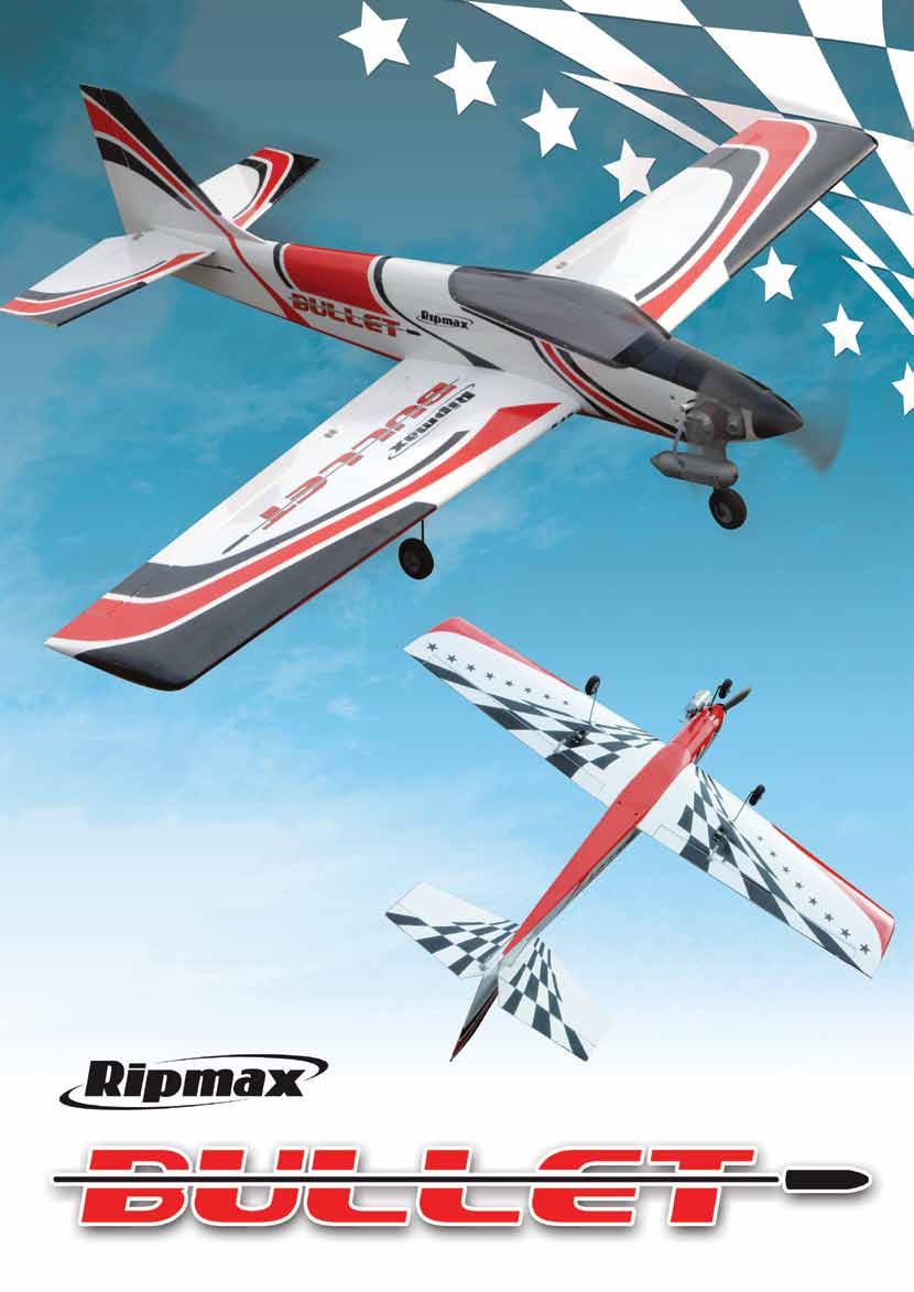
2 Congratulations on your purchase of the Bullet ARTF - the first Almost Ready to Fly version of this classic lowwinger. Based on the original and timeless Bullet design, the new Ripmax Bullet ARTF has been scaled up by 10% to make to most of today's more powerful engines. This also gives a lighter wing loading and improved flying characteristics. Assembly is quick and easy, but before commencing construction, please ensure that you read these instructions in their entirety. STEP 1 Locate the pre-cut servo apertures in the underside of the wing. Carefully trim away the covering to expose these apertures using a sharp knife. STEP 2 Check the fit of your chosen aileron servos in the apertures and adjust with a sharp knife if necessary. Prepare your servos by connecting a suitable 300mm extension lead to each. It is a good idea to use a lead-lock, a turn of insulation tape or heatshrink tube over the joint for additional security. Fit the rubber grommets and brass ferrules supplied with your servo. STEP 3 Pilot drill the mounting holes for each servo. Page 2


3 STEP 4 Install your servos as shown using the screws supplied with your radio noting that the servo output arms face towards the front of the wing. STEP 5 The wings and ailerons are supplied with the hinges loose fitted, ready for installation. Remove both ailerons and ensure that the hinges are inserted mid-way in their slots. Using thin cyano, pour a couple of drops onto each hinge - above and below - ensuring the glue soaks into the hinge and the surrounding wood. STEP 6 Carefully slide each aileron into position, ensuring a gap-free hinge line. Make sure that each aileron lines up with the wing tips and that they are free to move through their entire travel. Centre each aileron between the root and tip so that there is an equal gap at both ends. Minimise any hinge gap, then carefully add a couple of drops of thin cyano to the top and bottom of each hinge ensuring that the glue does not run through the hinge line onto the bottom of the wing. Turn the wing over and drop more cyano onto each hinge from the other side. STEP 7 Prepare the aileron pushrods by screwing on a nylon snap link and fuel tube keeper. Locate the aileron control horns. They are screwed in position on the ailerons in line with the aileron servo's output arm. Align the row of holes in the horn with the hinge-line. Mark and pilot drill two mounting holes. STEP 8 Screw the horn to the aileron. The screws thread into the moulded horn plate on the top surface of the wing. Page 3


4 STEP 9 Using side cutters, trim off any excess screw thread that passes through the moulded horn plate. STEP 10 Use a small length of tape to hold each of the ailerons at their neutral position while you complete the aileron linkages. Ensure that both aileron servos are centred. With the pushrod connected to its horn, mark the position the control rod passes over the servo s output arm. Bend the pushrod up at 90 at this point. STEP 11 Trim off the excess pushrod wire using side cutters. Repeat the procedure for the second aileron in exactly the same way. STEP 12 Now slide each aileron servo horn over their respective pushrods and re-fit to the servo. Adjust the pushrods to ensure that the ailerons are centred with the aileron servos at their neutral position. Test to ensure that both ailerons move freely across their entire throw then snap a moulded keeper onto the pushrod to retain it as shown. STEP 13 Locate the pre-cut grooves in the hardwood undercarriage mounting blocks. Carefully cut the covering at this point to allow the undercarriage legs to insert into the mounting blocks. Page 4


5 STEP 14 Install both undercarriage legs ensuring that they push down fully into their slots. STEP 15 Locate the undercarriage retaining saddle clamps. Note that two are used per leg. Pilot drill the undercarriage mounting blocks for the clamps - one at the inner and one at the outer end of the leg - and retain with the wood screws supplied. STEP 16 Fit the wheels using the collets supplied. File or grind a flat on the axle where the point of the grub screw contacts to reduce the risk of it slipping. Ensure the wheel spins freely and using threadlock, tighten the grubscrew securely. Repeat for the other wheel. STEP 17 Locate the wing joining brace. Note the orientation - the top of the brace is straight and the bottom has a slight dihedral angle. Measure and mark a centre-line on the joining brace. STEP 18 Coat the inside of the corresponding slot in the wing panel and one half of the brace with 5 minute epoxy. Ensure that adequate epoxy is used to fully cover all surfaces. Page 5


6 STEP 19 Insert the brace half-way into one wing panel using the centre-line as a guide. Wipe off any excess epoxy. STEP 20 Protect the covering with masking tape, then spread sufficient slow setting epoxy over the opposite panel joiner slot, wing joiner and root rib. Bring the two panels together ensuring the epoxy fills the join. Wipe off any excess that squeezes out of the joint, then use tape to hold the panels together as the adhesive cures. STEP 21 Locate the pre-drilled wing mounting bolt holes in the wing. Use a sharp knife to remove the covering from the holes as shown. STEP 22 Temporarily bolt the wing to the fuselage using the two nylon retaining bolts. Holding the underwing fairing in place - ensuring it is centred front and back, left and right - mark its position with a felt pen. Do not press too hard on the fairing otherwise it may distort and spread wider than the fuselage. STEP 23 Remove the fairing and carefully trim inside the lines you just marked using a sharp knife. VERY IMPORTANT: Make sure that you do not cut into the wood otherwise the strength of the wing will be severely weakened. Remove the wing bolts. Page 6


7 STEP 24 Glue the plywood wing bolt reinforcing plate in place using 5 minute epoxy. Use the wing bolts to hold the plate in position while the epoxy cures but take care not to get adhesive on the threads. STEP 25 Protect the fuselage with clear tape or film so that you do not accidentally glue the wing to the fuselage in this step. Using 5 minute epoxy or thick cyano, run a bead of glue around the perimeter of the underwing fairing. Avoid using too much glue as any excess will simply run out onto the wing covering or bond the fairing to the fuselage rather than the wing. Use strips of masking tape to hold the fairing in place until the glue dries. STEP 26 Using a sharp knife, carefully remove the film from the slot in both sides of the fuselage where the tailplane will mount. STEP 27 Trim away the covering to expose the slots for the elevator and rudder pushrods. STEP 28 Carefully measure and mark the tailplane's centre line. Page 7


8 STEP 29 Slide the tailplane into its pre-cut slot in the rear of the fuselage. Ensure that it is square to the fuselage and centred in its slot using a long ruler or string as shown in the diagram. STEP 30 Mark the tailplane on the top and bottom where it enters the fuselage using a soft, water-soluble pen. STEP 31 Remove the tailplane and cut away the covering from just inside the marked lines to give a film-free surface for the glue to bond. IMPORTANT: Ensure that only the film is cut - not the tailplane - as this will seriously weaken the structure. STEP 32 With the covering removed, the tailplane is ready to be installed. If necessary, use a warm covering iron to ensure the edges of the film are firmly adhered. STEP 33 Now loosely position the elevator joiner at the rear of the tailplane slot. This is an important step as it is almost impossible to fit after the tailplane is installed. Slide the tailplane into position. Page 8
.")


9 STEP 34 Check that the tailplane is correctly aligned, square to the fuselage and level with the wings. Glue in position using cyanoacrylate glue (cyano). Alternatively, if using epoxy, use masking tape to protect the covering (removing it as soon as you are satisfied with the alignment and before the epoxy cures). Any excess epoxy can be wiped from the model before it cures using methylated spirit or methanol. STEP 35 Insert three hinges in each elevator half, ensuring they are located mid-way in their slots. Using thin cyano, pour a couple of drops onto each hinge - above and below - ensuring the glue soaks into the hinge and the surrounding wood. STEP 36 Slide the fin into its pre-cut slot in the top of the fuselage. Ensure that it is pushed down far enough to touch the top of the tailplane. Mark the fin on both sides where it enters the fuselage using a soft, water-soluble pen. STEP 37 Remove the fin and cut away the covering from just below the marked lines to give a film-free surface for the glue to bond. IMPORTANT NOTE: Ensure that only the film is cut - not the fin - as this will seriously weaken the structure. If necessary, use a warm covering iron to ensure the edges of the film are firmly adhered. Glue the fin in position ensuring that it is firmly pushed down in its slot. Make sure the fin is at right angles to the tailplane and allow the glue to dry. STEP 38 Apply epoxy to one elevator half in the slot where the wire joiner will be fitted. Use a scrap of piano wire to force adhesive into the hole as shown. If you wish, protect the rear of the tailplane from the epoxy with a couple of strips of masking tape. Page 9


10 STEP 39 Now slide the first elevator into position ensuring that the joiner enters the hole in the elevator and all three hinges enter their pre-cut slots in the tailplane. Ensuring a gap-free hinge line, align the end of the elevator with the tip of the tailplane. STEP 40 Apply a couple of drops of thin cyano to the top and bottom of each hinge. Make sure that the glue does not run through the hinge line onto the bottom of the tail. Repeat for the second elevator half ensuring both elevator halves are in line with each other. STEP 41 Insert four hinges into the rudder, ensuring they are located mid-way in their slots. Using thin cyano, pour a couple of drops onto each hinge - from above and below - ensuring the glue soaks into the hinge and the surrounding wood. STEP 42 Now slide the rudder into position making sure that all hinges enter their pre-cut slots in the fin. With a gap-free hinge line, ensure that the top of the rudder is aligned with the top of the fin. Now add a couple of drops of thin cyano to both sides of each hinge. Make sure that the glue does not run through the hinge line onto the other side of the fin. STEP 43 Temporarily fit your spinner backplate and propeller. Place your engine on the pre-fitted mount and adjust its position until the rear of the spinner backplate is 107mm in front of the firewall. Page 10


11 STEP 44 Hold your engine steady and mark the positions of the mounting holes on the mount. STEP 45 Remove the engine and pilot drill four holes through the engine mounting beams to suit the self tapping screws supplied. Screw the engine to the mount. STEP 46 Locate the nosewheel mount and screw it in position on the bulkhead using the self tapping screws provided. STEP 47 Prepare the noseleg by installing the wheel with the collet supplied. File or grind a flat on the axle where the point of the grub screw contacts to reduce the risk of it slipping. Ensure the wheel spins freely and tighten the grubscrew securely. STEP 48 Locate the steerable noseleg pushrod and install the moulded steering arm onto the z-bent end. Insert the pushrod into its tube, then holding the steering arm in position, slide the noseleg into its mount. Ensuring that the steering arm is straight, tighten the retaining grubscrew with an allen driver. Page 11


12 STEP 49 Screw a plastic snap link onto the end of the throttle pushrod. Slide the pushrod into its outer and connect the snap link to the carburettor throttle lever. Retain using a short length of fuel tube as shown. STEP 50 You can now install your servos in the pre-fitted servo tray. Note the servos' orientation and after pilot drilling the tray and fitting the rubber grommets and brass ferrules supplied with your servos, install them using the screws supplied with your radio. STEP 51 Feed a scrap length of snake outer tube through the fuselage from rear to front to aid guiding the rudder pushrod throughout the fuselage and out through its slot under the tail. STEP 52 Using the snake outer to lead it through, feed the rudder pushrod through the fuselage and out through its exit. STEP 53 Now screw a nylon clevis onto the pushrod as shown. Connect to a control horn and holding the horn in line with the rudder hinge line, mark and pilot drill two mounting holes in the rudder. Page 12


13 STEP 54 Now screw the horn to the rudder. STEP 55 The screws thread into the moulded horn plate on the other surface of the rudder. STEP 56 Carry out the above 5 steps again to complete the elevator linkage. STEP 57 Move to the radio bay and complete each linkage by screwing on a nylon clevis and connecting to the appropriate servo. Note that the steerable noseleg pushrod connects to the same side of the rudder servo horn, inboard of the the rudder pushrod. The throttle linkage uses a steel pushrod connector for easy adjustment. STEP 58 Prepare the fuel tank for fitting by assembling the tank stopper with the feed, vent and fuel pipes. Ensure the clunk tube length is cut to allow the clunk to move around the tank without catching on the tank's base. Fit the assembled tank bung and tighten the retaining screw. Take care not to over-tighten this screw. Test that the tank is leak-proof. Page 13


14 STEP 59 The tank is installed in its bay via the radio bay. Fit and identify your fuel tubes, then feed the tank into position, drawing the fuel tubes out through the hole in the centre of the firewall. Connect the fuel line to your engine, pressure line to the silencer and blank off the vent line. STEP 60 Connect and install your receiver in the radio bay with plenty of shock absorbing foam. Temporarily install your radio's battery in the radio bay. Its final position is determined after balancing the model. STEP 61 Make a card template to clear the shape of the engine and tape it in position on the fuselage as shown. Temporarily remove the engine. STEP 62 Prepare the cowl by adding strips of masking tape to aid marking it for cutting. Slide the cowl in place and transfer the shape to be cut out using a felt tip pen. STEP 63 Now remove and trim the fibreglass cowl to clear the engine and silencer using the shape you transferred as a guide. The engine can now be re-fitted. Page 14

15 STEP 64 The cowl should just overlap the front of the fuselage. Carefully pilot drill the cowl and firewall and retain the cowl with four self tapping screws; two on each side. Fit your propeller and spinner, then cut a suitable aperture to fit your radio's switch to the left hand side of the fuselage. The model is complete and ready for balancing and setting up the control throws. Control THROWS For initial flights, we recommend the following control throws - each measured at the widest point of the surface: Elevator: Rudder: Ailerons: 18mm up 18mm down Maximum possible each way - 25mm+ each way 15mm up 15mm down BALANCING THE BULLET The Centre of Gravity (C/G or Balance Point) should be 80mm +/-5mm (3.25" +/-0.25") back from the leading edge of the wing at the root. This should be measured with the fuel tank empty. Support the completed model under the wing either side of the fuselage at this point and add weight or adjust the position of the radio battery in its bay as necessary to achieve a slightly nose down attitude. A model that is not correctly balanced will not perform as it should and, at worst, be unstable or unflyable, leading to damage to the model or injury to yourself or others. Do not miss out this step in completing your Bullet! Pre-flight checks Completely charge your transmitter and receiver batteries before flying. Carefully check your model over to ensure that all screws are tight and everything is well bonded. Double-check the Bullet s Centre of Gravity. Check the control surfaces for both the correct throw and direction. Ensure that each surface moves freely, without any binding. Check the receiver aerial(s) are correctly installed. Ensure the wing bolts are tight. While the Bullet is not suitable as a first model, it does make an excellent second low-wing model with reduced control throws and an engine from the lower end of the range. In this case, we recommend that your completed model is checked over and test flown by a competent pilot first. Subsequent flights should also be supervised, and assisted where necessary, by an experienced pilot. Always fly the Bullet in a safe location at a recognised club. For further information on flying in the UK, please contact: British Model Flying Association (BMFA) Chacksfield House, 31 St Andrews Road, Leicester. LE2 8RE. Tel: (+44) Fax: (+44) SPARE PARTS AND SERVICE Spare parts are available for the Bullet ARTF from all Ripmax stocked model shops. In case of any difficulty, any product queries, or to locate your local Ripmax stockist, please write to the address below or visit Always fly responsibly and safely. Page 15

16 Distributed to your local model shop by: Ltd., 241 Green Street, Enfield, EN3 7SJ. United Kingdom Made in China Page 16
Chris Foss. WOT 4-E - Instructions. The Designer. Chris Foss outside his factory in 1990
 Part No: A-CF003 The Designer WOT 4-E - Instructions Chris Foss Chris Foss outside his factory in 1990 The fascination of flight captured Chris's imagination early on in his life when he started building,
INSTRUCTION MANUAL. Suitable for Electric or I.C. Engine Power
 INSTRUCTION MANUAL Suitable for Electric or I.C. Engine Power Congratulations on the purchase of your Irvine Tutor 40 II Radio Control Model Aircraft. Please take some time to carefully read these instructions
Instruction Manual. Specification:
 Instruction Manual H I G Specification: Wingspan: 133 cm (52.3 inches) Length : 104 cm (40.9 inches) Weight : 1830gr Engine : 25-32 two stroke Radio : 4 channel - 4 servo H W I N G KIT CONTENTS: We have
INSTRUCTION MANUAL BOOK.
 INSTRUCTION MANUAL BOOK. SPECIFICATION Wingspan : 164 cm 64.57in. Length : 135 cm 53.15 in. Weight : 3.3kg 7.26 lbs. Servo : 7 servos. Radio : 4 channels. Engine : 61 cu.in-2 stroke. 91 cu.in-4 stroke.
FUJI FA-200 AERO SUBARU
 FUJI FA-200 AERO SUBARU SEMI SCALE SPORT MODEL AERO SUBARU Assembly and Operations Manual Please review this manual throughly Before assembling or Operating The AERO SUBARU Semi scale sport model We ve
RESolution V2 Manual
 RESolution V2 Manual Note for the German Manual: Yellow Bottle thick CA Pink Bottle Med CA Blue tube 5 minute Epoxy Green tube 90 Minute Epoxy Construction of the Fuselage Step 1: Cover the plan with a
105" TIGER MOTH ARF INSTRUCTION MANUAL VERSION 1.0
 105" TIGER MOTH ARF INSTRUCTION MANUAL VERSION 1.0 Step 1. Installation of the aileron servos 1) Mount aileron servo to servo mounting blocks with servo s screws. Install servo mounting plate with screws.
INSTRUCTIONS FOR FINAL ASSEMBLY
 MS: 11 INSTRUCTIONS FOR FINAL ASSEMBLY Graphics and specfications may change without notice. Specifications: Wingspan -------------------------------------------- 156 cm, 61.42 in. Wing area ---------------------------------
MECOA EZ-4061 Trainer
 MECOA EZ-4061 Trainer EZ-4061 is a newly designed, Almost Ready to Fly kit. It is an extremely easy to control trainer with strong construction and excellent aerodynamic performance. This is a great choice
FUSELAGE CONSTRUCTION
 FUSELAGE CONSTRUCTION Note: prior to building and gluing on the work surface use protective covering on your building surface. (wax paper or clear wrap) Fit the laser cut Fuselage Front and Fuselage Rear
TWEETY 25 INSTRUCTION MANUAL. Almost Ready to Fly Nitro/Electric Aerobat FEATURES SPECIFICATIONS
 TWEETY 25 Almost Ready to Fly Nitro/Electric Aerobat INSTRUCTION MANUAL SPECIFICATIONS FEATURES WINGSPAN: 45.7 (1160mm) LENGTH: 38.6 (980mm) WING AREA: 370 sq in(24 sq dm) FLYING WEIGHT: Approx. 3.3 lbs
Hand-made Almost Ready to Fly R/C Model Aircraft ASSEMBLY MANUAL
 Hand-made Almost Ready to Fly R/C Model Aircraft ASSEMBLY MANUAL Specifications Wingspan -----------------------.148 cm--------------- 58.3 in. Wing area ----------------------- 3474sq. cm ---- 538.4sq
Instruction Manual book
 Instruction Manual book ITEM CODE BH53. SPECIFICATION Wingspan : 1,250mm 49.21 in. Length : 930mm 36.61in. Weight : 1.1kg 2.42 Lbs. Parts listing required (not included). Battery: 3 CELLS-LI-POLY-11.1V-2,500
Citabria Pro. Aerobatic Parkflyer. by Joel Dirnberger
 Citabria Pro Aerobatic Parkflyer by Joel Dirnberger Revision C: December 21, 2004 Citabria Pro Building Instructions Length: Wingspan: Wing Area: Flying Weight: Wing Loading: Functions: Specifications:
DORNIER DO 27 SEMI SCALE SPORT MODEL DORNIER DO 27. Please review this manual throughly Before Assembling or Operating The DORNIER DO 27
 DORNIER DO 27 SEMI SCALE SPORT MODEL DORNIER DO 27 Assembly and Operations Manual Please review this manual throughly Before Assembling or Operating The DORNIER DO 27 Semi Scale Sport Model We ve used
MUSTANG P-51. Hand-made Almost Ready to Fly R/C Model Aircraft ASSEMBLY MANUAL
 MUSTANG P-51 Hand-made Almost Ready to Fly R/C Model Aircraft ASSEMBLY MANUAL Specifications Wingspan---------------------------------------- 60.5 in----------------------- 153.7cm. Wing area-------------------------------------
LANDING GEAR. 1. Fit landing gear into slots on bottom of fuselage.
 LANDING GEAR 1. Fit landing gear into slots on bottom of fuselage. 4. Use channel-lock pliers to press blind nuts into position (note: drilled hole should be slightly smaller than shaft of blind nut for
ASSEMBLY & OPERATIONS MANUAL
 TM TM AERO SUBARU 40-52 ARF ECS SEMI SCALE MODEL WITH POLYCOTE ECS ENHANCED GRAPHICS SYSTEM #VMA-S140B (blue as shown) #VMA-S140R (red) This model may be produced in a number of different graphic schemes
DORNIER DO 27 SEMI SCALE SPORT MODEL DORNIER DO 27. Assembly and Operations Manual
 DORNIER DO 27 SEMI SCALE SPORT MODEL DORNIER DO 27 Assembly and Operations Manual Please review this manual throughly Before assembling or Operating The DORNIER DO 27 Semi scale sport model We ve used
AT channel 6 servos
 Wing Span: Wing Area: Fuselage Length: Flying weight: Power system: Radio: 60.7in/1540mm 561 sq in/36.3 sq dm 44.1in/1120mm 6.9 Ibs/ 3100g 46(2C0/71(4C) 5 channel 6 servos AT6-46 INSTALLING AILERONS Begin
Ryan STA Sport Scale Model Aircraft Assembly and Instruction Manual
 Ryan STA Sport Scale Model Aircraft Assembly and Instruction Manual Warning: This radio controlled model is not a toy. It requires skill to fly and is not recommended for the novice pilot. It should not
Edge 540 V3 35CC. Scheme A. Item No:L G Specifications. Flying Weight
 Edge 540 V3 35CC Item No:L G035016 Specifications Wing Span Length Wing Area Flying Weight Glow Gasoline Electric Radio Description 76 (1930mm) 74 (1879mm) 1200sq in(77.4sqdm) 9.9 12lbs(4.5 5.5kg) 91 1.20(2C)
EXTRA 330SC 60CC. Item No:H G Specifications cc gas DA50,DA60, DLE55, DLE60(twin), 3W55. Description
, 3W55. Description") EXTRA 330SC 60CC Item No:H G060011 Specifications Wing Span Length Wing Area Flying Weight Gasoline Radio Description Carbon Fibre : 92" (2347mm) 84 1/2 " (2060mm) 1526.8 sq in(98.5sq dm) 16 17lbs(7300
EXTRA 330SC 60CC Item No:H G060011 Specifications Wing Span Length Wing Area Flying Weight Gasoline Radio Description Carbon Fibre : 92" (2347mm) 84 1/2 " (2060mm) 1526.8 sq in(98.5sq dm) 16 17lbs(7300
Corvus Racer CC
 Corvus Racer 540 35CC Item No:L-G035008 Specifications Wing Span Length Wing Area Flying Weight Glow Gasoline Electric Radio mm mm 1200sq in (77.4sqdm) 9.9-12lbs(4.5-5.5kg) 91-1.20(2C) 1.10-1.40(4C) 20-40cc
SPUNKY ASSEMBLY MANUAL
 SPUNKY ASSEMBLY MANUAL Please read the tips section at the back of this manual regarding the use of laser cut parts. The proper removal and preparation of these parts is important. When laser cut, some
Building Instructions. Scarlet RC model aircraft. Order No. 1308/00. Specification: approx mm. rudder, flaps, throttle.
 Building Instructions RC model aircraft Order No. 1308/00 Specification: Wingspan Length Wing area All-up weight Wing loading RC functions approx. 3000 mm approx. 1270 mm approx. 53.5 dm² approx. 1.45
THE APOGEE A 100-INCH AMA DURATION SAILPLANE FROM DYNAFLITE
 THE APOGEE A 100-INCH AMA DURATION SAILPLANE FROM DYNAFLITE Apogee is the intermediate sailplane designed to be competitive in AMA duration contests. Effective spoilers, rudder and full flying stabilizer
MXS R 30CC. Item No:L G Specifications. 67 1/2"(1720mm) (2C) (4C) 26 35cc gas DLE 30/35RA MLD35 JC30Evo.
 (2C) (4C) 26 35cc gas DLE 30/35RA MLD35 JC30Evo.") MXS R 30CC Item No:L G030008 Specifications Wing Span Length Wing Area Flying Weight Glow Gasoline Electric Radio Description Covering Material Carbon Fibre : 75"(1915mm) 67 1/2"(1720mm) 1023sq in(66sq
MXS R 30CC Item No:L G030008 Specifications Wing Span Length Wing Area Flying Weight Glow Gasoline Electric Radio Description Covering Material Carbon Fibre : 75"(1915mm) 67 1/2"(1720mm) 1023sq in(66sq
WE GET PEOPLE FLYING AT-6
 TM WE GET PEOPLE FLYING AT-6 Texan.60 ARF ASSEMBLY MANUAL Specifications Wingspan:... 67.5 in (1714mm) Length:... 48 in (1219mm) Wing Area:... 706 sq in (45.54 sq dm) Weight:... 7 8.5 lb (3.17 3.85 kg)
Extra 330LT CC. 2 Colour schemes H-G120001A ORACOVER FERRARI RED # ORACOVER WITH # ORACOVER BLACK # ORACOVER SILVER #
 Extra 330LT 85-125CC Item No:A-G120001 Specs: WING SPAN: LENGTH: WING AREA: FLYING WEIGHT: ENGINE: RADIO: Description Covering Material Carbon Fibre: 111 (2833mm) 100" (2530mm) 2139sq in (138sq dm) 25.3-28lbs
(Build Instructions)
") (Build Instructions) Specifications * Wingspan: 58cm * Length: 50cm * Flying Weight: 59 grams * Channels: 3 (Rudder Elevator Throttle) * Suggested Receiver: 4Ch Micro * Motor: 8mm GearDrive * Prop: GWS
(Build Instructions) Specifications * Wingspan: 58cm * Length: 50cm * Flying Weight: 59 grams * Channels: 3 (Rudder Elevator Throttle) * Suggested Receiver: 4Ch Micro * Motor: 8mm GearDrive * Prop: GWS
Hot Stik ARF WARNING. Copyright 2005 Carl Goldberg Products LTD CARL GOLDBERG PRODUCTS, LTD.
 Hot Stik ARF INSTRUCTIONS WARNING A radio-controlled model is not a toy and is not intended for persons under 16 years old. Keep this kit out of the reach of younger children, as it contains parts that
C-180 Builder s Manual
 C-180 Builder s Manual. May 20, 2002 Last revised July 11, 2002 Copyright! 2002 Douglas Binder, Mountain Models www.mountainmodels.com sales@mountainmodels.com (719) 630-3186 1 Required Equipment! Xacto
Corvus Racer Colour schemes. AeroPlus RC Copyright 2013 All Rights Reserved
 Corvus Racer 540 59 Item No:A E050003 Specifications WING SPAN: 59"(1500mm) LENGTH: 54.1"(1374mm) WING AREA: 654sq.in.(42.2sq.dm.) FLYING WEIGHT: 4.6 5.3lbs(2000 2300g) Electric:Brushless outrunner 8Oz.
RYAN STA SAFETY PRECAUTIONS. "Sport Scale E-Power ARF" For Intermediate and Advanced Fliers. This radio control model is not a toy!
 RYAN STA "Sport Scale E-Power ARF" For Intermediate and Advanced Fliers. SAFETY PRECAUTIONS This radio control model is not a toy! First-time builders should seek advice from people with model building
Specifications Wingspan: 43cm Flying Weight: 33 grams (with battery) Channels: 3 Suggested Receiver: 4Ch Micro Motor: 7mm Brushed Geardrive
 Channels: 3 Suggested Receiver: 4Ch Micro Motor: 7mm Brushed Geardrive") Specifications Wingspan: 43cm Flying Weight: 33 grams (with battery) Channels: 3 Suggested Receiver: 4Ch Micro Motor: 7mm Brushed Geardrive Airframe Kit (Included Contents) * Airframe Parts Sheets (Depron)
Specifications Wingspan: 43cm Flying Weight: 33 grams (with battery) Channels: 3 Suggested Receiver: 4Ch Micro Motor: 7mm Brushed Geardrive Airframe Kit (Included Contents) * Airframe Parts Sheets (Depron)
PERCIVAL P-56 PROVOST
 Instruction Manual Book. PERCIVAL P-56 PROVOST OLEO STRUTS LANDING GEAR. ALL BALSA - PLY WOOD CONSTRUCTION. COVERED WITH ORACOVER Glow and EP 95% ALMOST READY TO FLY SPECIFICATION: - Wingspan: 1,644mm
Pfalz E1 Monoplane 48 EZ Build Version
 Pfalz E1 Monoplane 48 EZ BUILD Pfalz E1 Monoplane 48 EZ Build Version R/C Scale Model Instructions CONTACT INFORMATION Designed by M.K. Bengtson Prototype by Robert Hoffman Manufactured and Distributed
30% Edge 540T Almost Ready to Fly
 Lanier R/C 30% Edge 540T Almost Ready to Fly WARNING! THIS IS NOT A TOY! THIS IS NOT A BEGINNERS AIRPLANE This R/C kit and the model you will build from it is not a toy! It is capable of serious bodily
uin RC FPRC ZERO Specificationss Empty Weight
 Flying Pengu uin RC FPRC ZERO Specificationss Wing Span 42.75 (1085 mm) Fuselage length 30.5 ( 775 mm) Empty Weight 9.5 10 oz. (150 160g) Estimated Flying Weight 20 255 oz. (320 400g) Wing Area: 151 sq.
Millennium RC presents The New and Improved (now even easier to build and cover!) SSX X-Trainer Build Kit
 SSX X-Trainer Build Kit") Millennium RC presents The New and Improved (now even easier to build and cover!) SSX X-Trainer Build Kit Wing span: Approx. 42 Wing Area: 504 sq. in. Wing Loading: 6.71 oz/ sq. ft. Introduction: The Slow
Millennium RC presents The New and Improved (now even easier to build and cover!) SSX X-Trainer Build Kit Wing span: Approx. 42 Wing Area: 504 sq. in. Wing Loading: 6.71 oz/ sq. ft. Introduction: The Slow
S.E.5a (Build Instructions)
") S.E.5a (Build Instructions) Specifications Wingspan: 38 cm Length: 31cm Flying Weight: 41 Channels: 3 (Rudder Elevator Throttle) Suggested Receiver: 3Ch Brick Motor: 7mm Geared Motor Airframe Only Kit
S.E.5a (Build Instructions) Specifications Wingspan: 38 cm Length: 31cm Flying Weight: 41 Channels: 3 (Rudder Elevator Throttle) Suggested Receiver: 3Ch Brick Motor: 7mm Geared Motor Airframe Only Kit
67 Edge 540 ARF WARNING
 67 Edge 540 ARF INSTRUCTIONS WARNING A radio-controlled model is not a toy and is not intended for persons under 16 years old. Keep this kit out of the reach of younger children, as it contains parts that
Assembly Manual / Airframe 65 Vyper SAFETY in Assembly SAFETY in Flying
 1 Assembly Manual / Airframe 65 Vyper Thank you for purchasing this 3DHobbyShop ARF RC aircraft. If you have any issues, questions, concerns or problems during assembly, please contact our tech department
FLITZEBOGEN-2 Assembly instructions
 FLITZEBOGEN-2 Assembly instructions Trim the end of the fuselage to the length of 925mm from the nose. Be careful to avoid splitting the carbon fibers. Sand the base of the stab mount in preparation for
A S S E M B L Y M A N U A L
 A S S E M B L Y M A N U A L Kit features. Ready-made minimal assembly & finishing required. Ready-covered covering. Photo-illustrated step-by-step Assembly Manual. Specifications Wingspan --------------------------
HIGH-END TECHNOLOGY. Electric ducted fan Starfighter
 HIGH-END TECHNOLOGY RC Electric ducted fan Starfighter First we want to thank and congratulate you with your decision in buying one of our Kits. The Starfighter puts together very easily so there is not
Instruction Manual book
 Instruction Manual book ITEM CODE: BH50. SPECIFICATION Wingspan : 1,600 mm 62.99 in. Length : 1,230 mm 48.43 in. Weight : 2.5 kg 5.5 Lbs. Radio : 06 channels. Servo : 07 servos. Electric Motor : ( 02pcs
Zeon PDF Driver Trial
 Mach Dart Slope Soarer Congratulations on your purchase of the Mach Dart Glider. This aircraft was crafted utilizing the latest technology in composite model aircraft design and manufacture. The Dart is
HAWKER HURRICANE. Instruction Manual Book 95% ALMOST READY TO FLY. Item code: BH147. SPECIFICATION
 Instruction Manual Book Item code: BH147. HAWKER HURRICANE ALL BALSA - PLY WOOD CONSTRUCTION. COVERED IN A HEAT-SHRINK FILM WITH PRINTED. 95% ALMOST READY TO FLY SPECIFICATION Wingspan: 1,520 mm (59.84
Super Sky Surfer 2000 Assembly Instructions
 Super Sky Surfer 2000 Assembly Instructions Note: Plug and Play version of the Sky Surfer comes with fuselage pre-glued and motor/servos installed. If you wish to route antennas or wires through the tail,
High performance 90mm fiberglass jet
 High performance 90mm fiberglass jet Assembly manual For intermediate and advanced fliers only! Specs Wingspan: 1255mm Fuselage length: 1250mm Flying weight: 2600-3000g Wing area: 22.6 dm² Wing loading:
BUCKER BU 131 JUNGMANN ALL BALSA - PLY WOOD CONSTRUCTION. COVERED WITH ORACOVER
 Instruction Manual Book. BUCKER BU 131 JUNGMANN ALL BALSA - PLY WOOD CONSTRUCTION. COVERED WITH ORACOVER Glow and EP 95% ALMOST READY TO FLY SPECIFICATION: - Wingspan: 1,850 mm (72.83 in). Length: 1,660
NOORDUYN NORSEMAN. Instruction Manual Book 95% ALMOST READY TO FLY. Item code: BH157. SPECIFICATION
 Instruction Manual Book Item code: BH157. NOORDUYN NORSEMAN ALL BALSA - PLY WOOD CONSTRUCTION. COVERED WITH ORACOVER. 95% ALMOST READY TO FLY SPECIFICATION - Wingspan: 1840 mm (72.44 in). - Length: 1180
CARL GOLDBERG PRODUCTS, LTD.
 Eagle 400 WARNING A radio-controlled model is not a toy and is not intended for persons under 16 years old. Keep this kit out of the reach of younger children, as it contains parts that could be dangerous.
Post-Paint>Fuselage>Interior>Controls>Fit rudder pedals
 Post-Paint>Fuselage>Interior>Controls>Fit rudder pedals Objectives of this task: To fit the rudder pedals and steering links to the aircraft, and fit the rudder cable to the rudder pedals and set the deflection
Preliminary pilot information
 Recommended RC-components: Preliminary pilot information RC-component suggestions for Freestyler 3, V-tail version FLAPS AILERONS V-tail receiver battery low-cost HS85 MG HS85 MG HS81 MG SMC 14 4 x AA
ULS Cherokee. Ultra Low Speed aircraft for indoor RC flying. Zippkits. Specifications: Required to complete:
 Zippkits ULS Cherokee Ultra Low Speed aircraft for indoor RC flying. Specifications: Span- 28 inches Wing Area- 151 Sq/In Wing Loading- 3.0 ounces/ft Weight- 3.5 ounces RTF Build time- 1-2 Hours Radio-
SZD-10 bis CZAPLA ASSEMBLY MANUAL IN PICTURES
 1 RUDDER Plan and parts: 2 Assembly steps: Photo above: glue together rudder spar, ribs and trailing edge. Clamp spar to a flat surface (chipboard on the photo) and make sure the straight aligment of the
Cheeper Assembly instruction
 1. Equipment, materials and tools for assembly.......2 2. Assembly.....3 3. Setting of the model.....11 1. Equipment, materials and tools for assembly 1 Wing; 2 Fuselage; 3 Stabilizer; 4 Fin; 5 Dowel for
Combat plane for Open B Lanier R/C Inc. P.O. Box 458 Oakwood, GA Phone Fax copyright 2003 Lanier R/C
 Combat plane for Open B Lanier R/C Inc. P.O. Box 458 Oakwood, GA. 30566 Phone 770 532 6401 Fax 770 532 2163 copyright 2003 Lanier R/C Important information: Please inspect the plane before beginning to
PITTS S2S CONSTRUCTION
 PITTS S2S CONSTRUCTION FUSELAGE CONSTRUCTION 1) Place the right fuselage side over the plan and mark the former positions. Place the left side over the right side and mark the former positions. Glue F1
ParkJet Builder s Manual
 ParkJet Builder s Manual Thank you for purchasing the ParkJet. The ParkJet is a profile ducted fan airplane that can be flown in a larger park. The ParkJet was initially designed by Scott Stoops and modified
INCLUDED IN THIS KIT: SPECIFICATION: NEEDED BUILDING TOOLS: REQUIRED EQUIPMENT:
 Please review this entire manual before beginning assembly. By doing so it will help you better understand each step as you progress in the actual building of your kit, and you will do a better job in
Aichi D3A1 INSTRUCTION MANUAL SAFETY PRECAUTIONS. Specification:
 Aichi D3A Specification: Length: 50mm(0. ) Wing span: 057mm( ) Wing area: 7.sq.dm(.sq.ft) Wing loading: 99.9g/sq.dm(3.oz/sq.ft) Flying weight: 7.kg(.7lbs) Radio: ch & 7servos Engine: 0 -cycle C.G: 35mm
F3A -70E ASSEMBLY MANUAL
 F3A -70E ASSEMBLY MANUAL The new F3A-70E, was designed in an extremely lightweight structure, the all wood airframe, and the new revolutionary Lift Generator on landing gear give the F3A-70E an impressive
Admas A500. Specification:
 Admas A500 Specification: Length :07 mm(8.7") Wing Span :00 mm(9.5") Wing Area :8.8 sq. dm 5.5 sq. ft Wing Loading :3 g/sq. dm 53.7 oz/sq. ft Flying Weight :8 kg(7.lbs) Radio :ch &3 servos Engine : -cycle
Assembly Instructions
 Congratulations AJ Aircra thanks you for the purchase of this airplane. Top grade materials and precision assembly has gone into this to make this a top quality aircra. Following the direcons closely,
Dandy Sport Builder s Manual
 Dandy Sport Builder s Manual Thank you for purchasing the Dandy Sport. The Dandy Sport has been designed as an easy to build aileron trainer. Take your time and enjoy building this plane. Specifications:
PROCTOR. Instruction Manual Book 95% ALMOST READY TO FLY. Item code: BH154. SPECIFICATION ALL BALSA - PLY WOOD CONSTRUCTION. COVERED WITH ORACOVER
 Instruction Manual Book PROCTOR Item code: BH154. ALL BALSA - PLY WOOD CONSTRUCTION. COVERED WITH ORACOVER 95% ALMOST READY TO FLY SPECIFICATION Wingspan: 1,360 mm (53.54 in). Length: 1,480 mm(58.27 in).
Cover the wing trailing edge and the aileron leading edge with strapping tape as shown.
 Cover the wing trailing edge and the aileron leading edge with strapping tape as shown. The aileron hinges are done using strapping tape on the top and bottom surfaces of the ailerons as shown. Make sure
RADIO CONTROL MODEL / RC FLUGMODELL INSTRUCTION MANUAL
 RADIO CONTROL MODEL / RC FLUGMODELL INSTRUCTION MANUAL SPECIFITIONS Wingspan...57.5 in. / 146cm Length...50 in. / 127cm Engine...46 2T /.70 4T or Electric equivalent. Radio...4 ~ 6 channel Almost ready
TIGER MOTH 120 ASSEMBLY INSTRUCTIONS
 TIGER MOTH 120 ASSEMBLY INSTRUCTIONS SPECIFICATIONS Wing Span: Length: Radio: Flying Weight: 1920mm 1580mm 4 channel with 6 servos 4200g AILERON ASSEMBLY 1 Start by removing the servo cover from the bottom
Assembly Instructions STINGER
 STINGER 120 ARF Important Information: Please inspect the plane before beginning to assemble to make sure you are happy with it. After assembly has begun you cannot return the kit. If you find a problem
第 4 页, 共 17 页. 3. Epoxy the wood block to the servo tray base on the mark line. Accessory part lists for wing installation.
 第 1 页, 共 17 页 第 2 页, 共 17 页 第 3 页, 共 17 页 Accessory part lists for wing installation. 3. Epoxy the wood block to the servo tray base on the mark line. 1. Ready for assemble the wing servos. 4. Epoxy the
94 Yak 54 ARF WARNING
 94 Yak 54 ARF WARNING A radio-controlled model is not a toy and is not intended for persons under 16 years old. Keep this kit out of the reach of younger children, as it contains parts that could be dangerous.
Assembly Instructions. Stinger 120. Almost Ready to Fly
 Stinger 120 Almost Ready to Fly Important Information: Please inspect the plane before beginning to assemble to make sure you are happy with it. After assembly has begun you cannot return the kit. If you
Velocity Slingjet. Specifications: Construction Span Length Take-off weight w/ gear. Balsa/foam/film 1055m m (41.54 ) 1040m m (40.
 1040m m (40.") Velocity Slingjet Specifications: Construction Span Length Take-off weight w/ gear Recommended servos w/o nose-steering Recommended fan Recommended motor Recommended controller Balsa/foam/film 1055m m
Velocity Slingjet Specifications: Construction Span Length Take-off weight w/ gear Recommended servos w/o nose-steering Recommended fan Recommended motor Recommended controller Balsa/foam/film 1055m m
77 Edge 540 ARF WARNING
 77 Edge 540 ARF INSTRUCTIONS WARNING A radio-controlled model is not a toy and is not intended for persons under 16 years old. Keep this kit out of the reach of younger children, as it contains parts that
Stream NXT - assembly instructions
 Stream NXT - assembly instructions Recommended settings CG (measured from root leading edge): Speed/launch camber (+down, near the wing root): Cruise camber (+down, near the wing root): Thermal camber
I hope you enjoy the Spirit as much as I have. Scott DeTray Model Aero
 We are excited to introduce the Model Aero Spirit. Inspired by the magnificent Northrop Grumman B-2 Spirit Stealth Bomber, the Spirit is a great flyer, on land or water. It tracks like an arrow and is
HIGH-END TECHNOLOGY. Electric ducted fan rafale
 HIGH-END TECHNOLOGY RC Electric ducted fan rafale First we want to thank and congratulate you with your decision in buying one of our Kits. The Rafale puts together very easily so there is not much explanation
L 410 UVP-E Turbolet. Recommended equipment and guide for the building of RC model aircraft.
 L 410 UVP-E Turbolet Recommended equipment and guide for the building of RC model aircraft. - 1 - History of L-410 It has been 45 years since the first small commercial L-410 prototype took off. The first
Instruction Manual. Item No: AL001
 Instruction Manual Item No: AL001 Specifications: Wingspan: 2037mm (80.2 in) Length: 1677mm (66 in) Wing Area: 65.5dm2 (1015.3 sq in) Flying Weight: 7.6kg (16.7 lbs) Engine(not incl.): 45-50cc Gas Radio(not
E-AERO EPP PITTS KIT From BP HOBBIES. Parts Included in kit
 E-AERO EPP PITTS KIT From BP HOBBIES Parts Included in kit Thank you for purchasing the BP Hobbies/E-aero EPP Pitts. Please take the time to read through the instruction manual before beginning the build.
FAIREY ALBACORE. Instruction Manual Book. Glow and EP. Item code: BH % ALMOST READY TO FLY SPECIFICATION:
 Instruction Manual Book. FAIREY ALBACORE ALL BALSA - PLY WOOD CONSTRUCTION. COVERED IN A HEAT-SHRINK FILM WITH PRINTED. Glow and EP 95% ALMOST READY TO FLY SPECIFICATION: - Wingspan: 1,693mm (66.65in).
Aviator Trainer40 ARF Instruction Manual Specifications
 Aviator Trainer40 ARF Instruction Manual Specifications Wingspan: 65.0 in (1650 mm) Length: 53.1 in (1350 mm) Wing Area: 729sq in (47.0 sq dm) Flying Weight: 5.3 lbs (2400g) Dear Customer, Congratulations
Pfalz E1 48. R/C Scale Model Instructions CONTACT INFORMATION. The Pfalz E1 was designed by M.K. Bengtson Prototype by Jack Richardson
 Pfalz E1 48 Pfalz E1 48 R/C Scale Model Instructions CONTACT INFORMATION The Pfalz E1 was designed by M.K. Bengtson Prototype by Jack Richardson Manufactured and Distributed by: Bengtson Company e mail:
Sbach 1,2m 3D/aerobatic EPP model Building instructions
 Sbach 1,2m 3D/aerobatic EPP model Building instructions Please refer to the Diagram sheet Diagrams A, B Press 2 carbon strips (1x3x1000 mm) into the grooves in the sides of the fuselage central part (the
Building instructions SHK scale glider
 Building instructions SHK scale glider RC glider Order No. 1125/00 Specification: Wingspan 4000 mm Length 1501 mm Wing area 82 dm² Geometrical aspect ratio 20.2 All-up weight approx. 4300 g Wing loading
Zlín Z-37A Čmelák ("Bumblebee ) 850 mm. Assembly Instructions and recommended equipment of the RC model
 850 mm. Assembly Instructions and recommended equipment of the RC model") Zlín Z-37A Čmelák ("Bumblebee ) 850 mm Assembly Instructions and recommended equipment of the RC model 1 Technical information: Wingspan: Overall Length: Flying weight: RC Functions: 850 mm 610 mm ~380
Zlín Z-37A Čmelák ("Bumblebee ) 850 mm Assembly Instructions and recommended equipment of the RC model 1 Technical information: Wingspan: Overall Length: Flying weight: RC Functions: 850 mm 610 mm ~380
Elf Manual 2e 06/01/2012
 Elf Manual 2e 06/01/2012 ELF - a low weight mosquito class 1m span discus launched glider. The ELF allows the pilot to soar in small places as never before. ELF s high tech construction makes the model
F - 4u Corsair (50cc)
") F - u Corsair (50cc) Specification: Length: 73(.3") Wing span: 0mm(5") Wing area: 7.00sq.dm(9.39sq.ft) Wing loading: 35.g/sq.dm(.5oz/sq.ft) Flying weight:.kg(.0lbs) Radio: ch & 0servos Engine: 50cc gasoline
F - u Corsair (50cc) Specification: Length: 73(.3") Wing span: 0mm(5") Wing area: 7.00sq.dm(9.39sq.ft) Wing loading: 35.g/sq.dm(.5oz/sq.ft) Flying weight:.kg(.0lbs) Radio: ch & 0servos Engine: 50cc gasoline
Nieuport 11 Bebe. R/C Scale Model Instructions. CONTACT INFORMATION The Nieuport 11 Bebe was designed by Peter Rake and M.K.
 Nieuport 11 Bebe 49 Nieuport 11 Bebe R/C Scale Model Instructions CONTACT INFORMATION The Nieuport 11 Bebe was designed by Peter Rake and M.K. Bengtson Manufactured and Distributed by: Bengtson Company
LANIER - Ultimate Pitts - INSTRUCTIONS. Additional Parts Required. (12) 4-40 blind nuts (Dubro #606)
 4-40 blind nuts (Dubro #606)") Additional Parts Required (4) or more channel radio with 7-8 servos..91-2.2 two stroke or 1.20-1.84 four stroke engine Appropriate Master Airscrew prop and Hayes mount for your engine. 3 Tru-Turn spinner
Additional Parts Required (4) or more channel radio with 7-8 servos..91-2.2 two stroke or 1.20-1.84 four stroke engine Appropriate Master Airscrew prop and Hayes mount for your engine. 3 Tru-Turn spinner
INCLUDED IN THIS KIT: SPECIFICATION: NEEDED BUILDING TOOLS: REQUIRED EQUIPMENT:
 Please review this entire manual before beginning assembly. By doing so it will help you better understand each step as you progress in the actual building of your kit, and you will do a better job in
JAMISON SPECIAL. Building Guide
 JAMISON SPECIAL Building Guide WING Mark then drill holes for wing jig rods. Slide Ribs onto jig rods Mark the rib positions on 1/16 x 1 trailing edge, 1/4 x 1/4 leading edge & 1/4 x 1/4 spars Pin ribs
43in EPP Acrocub Instruction Manual
 43in EPP Acrocub Instruction Manual Specifications Wingspan: 43.3in (1100mm) Length: 41.3in (1050mm) Flying Weight: Approx. 1.5lb (670g) Dear Customer, Congratulations on your purchase of 43in EPP Acrocub
Parts Identification
 We are excited to introduce the Model Aero Aqua Sport. This is an excellent sport flyer, equally at home flying from grass fields, water, or even snow! The unique V-tail gives the Aqua Sport a distinctive
28in Super EVA Foam. F-22 Raptor Kit. Specifications. Wingspan: 27.5in (700mm) Length: 38.3in (975mm) Flying Weight: Approx. 1.
 Length: 38.3in (975mm) Flying Weight: Approx. 1.") 28in Super EVA Foam F-22 Raptor Kit Specifications Wingspan: 27.5in (700mm) Length: 38.3in (975mm) Flying Weight: Approx. 1.2lbs (530g) Dear Customer, Congratulations on your purchase of 28in F22 Raptor
28in Super EVA Foam F-22 Raptor Kit Specifications Wingspan: 27.5in (700mm) Length: 38.3in (975mm) Flying Weight: Approx. 1.2lbs (530g) Dear Customer, Congratulations on your purchase of 28in F22 Raptor